digital baseband modulation - sonoma state university · digital baseband modulation . ... • line...
TRANSCRIPT
Digital Baseband Modulation
Outline • Later
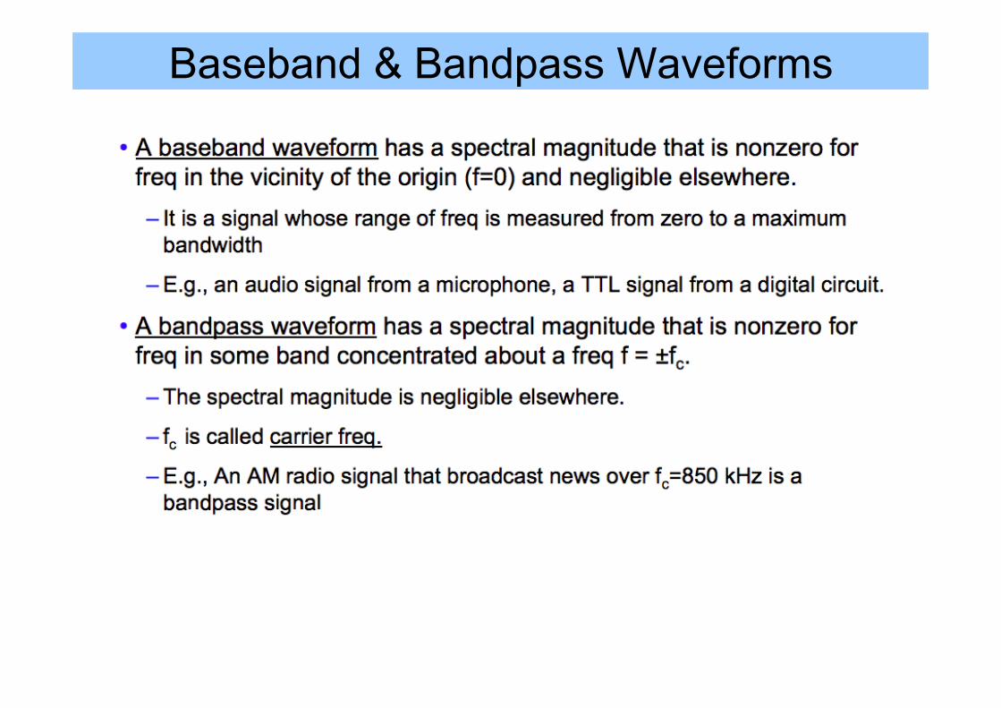
Baseband & Bandpass Waveforms
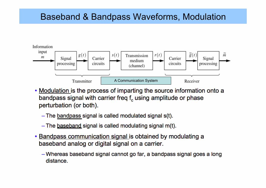
Baseband & Bandpass Waveforms, Modulation
A Communication System
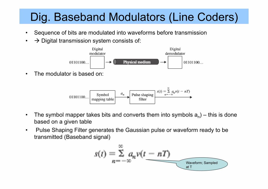
Dig. Baseband Modulators (Line Coders) • Sequence of bits are modulated into waveforms before transmission • à Digital transmission system consists of:
• The modulator is based on:
• The symbol mapper takes bits and converts them into symbols an) – this is done based on a given table
• Pulse Shaping Filter generates the Gaussian pulse or waveform ready to be transmitted (Baseband signal)
Waveform; Sampled at T
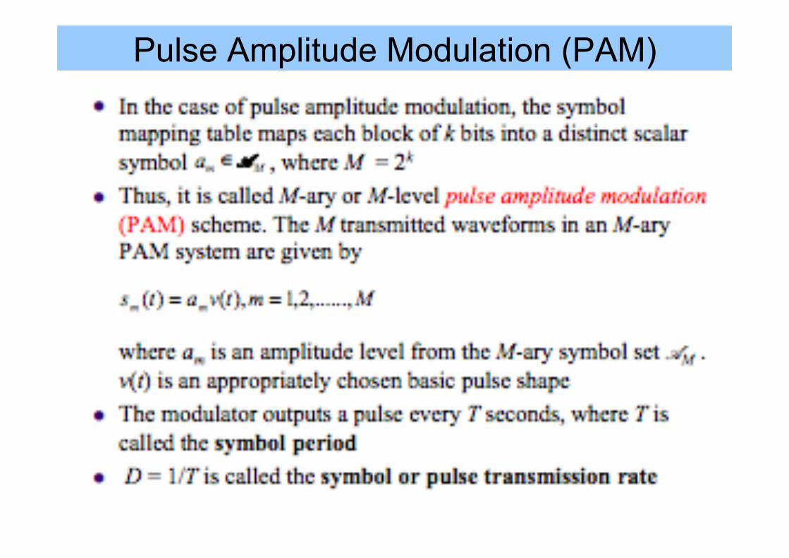
Pulse Amplitude Modulation (PAM)
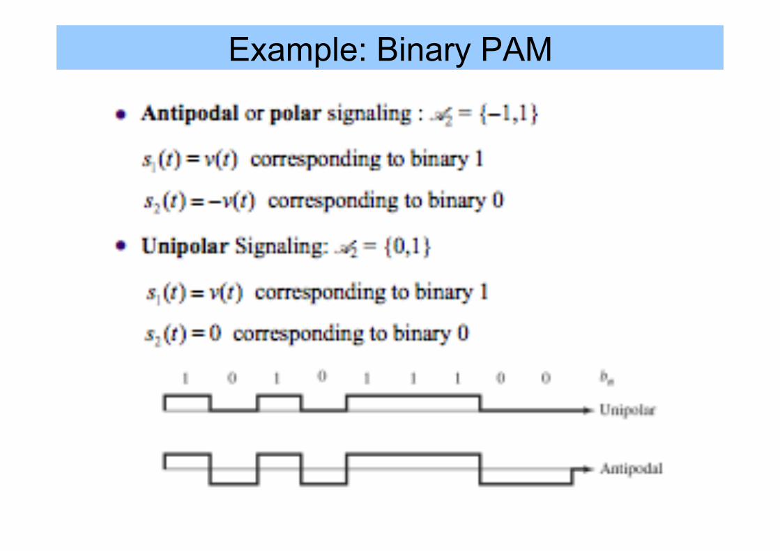
Example: Binary PAM
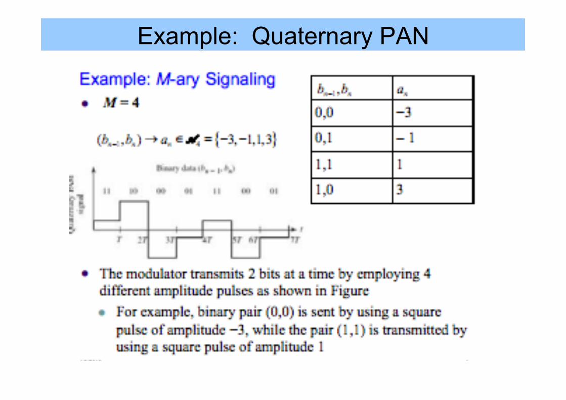
Example: Quaternary PAN
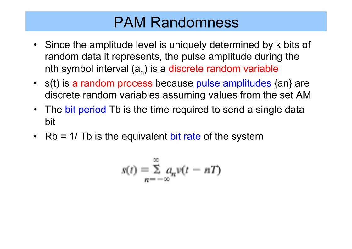
PAM Randomness • Since the amplitude level is uniquely determined by k bits of
random data it represents, the pulse amplitude during the nth symbol interval (an) is a discrete random variable
• s(t) is a random process because pulse amplitudes {an} are discrete random variables assuming values from the set AM
• The bit period Tb is the time required to send a single data bit
• Rb = 1/ Tb is the equivalent bit rate of the system
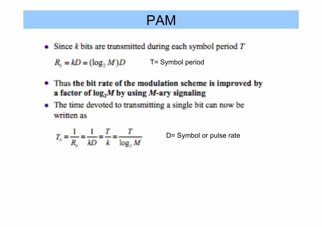
PAM
T= Symbol period
D= Symbol or pulse rate
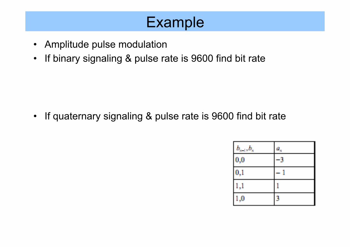
Example • Amplitude pulse modulation • If binary signaling & pulse rate is 9600 find bit rate • If quaternary signaling & pulse rate is 9600 find bit rate
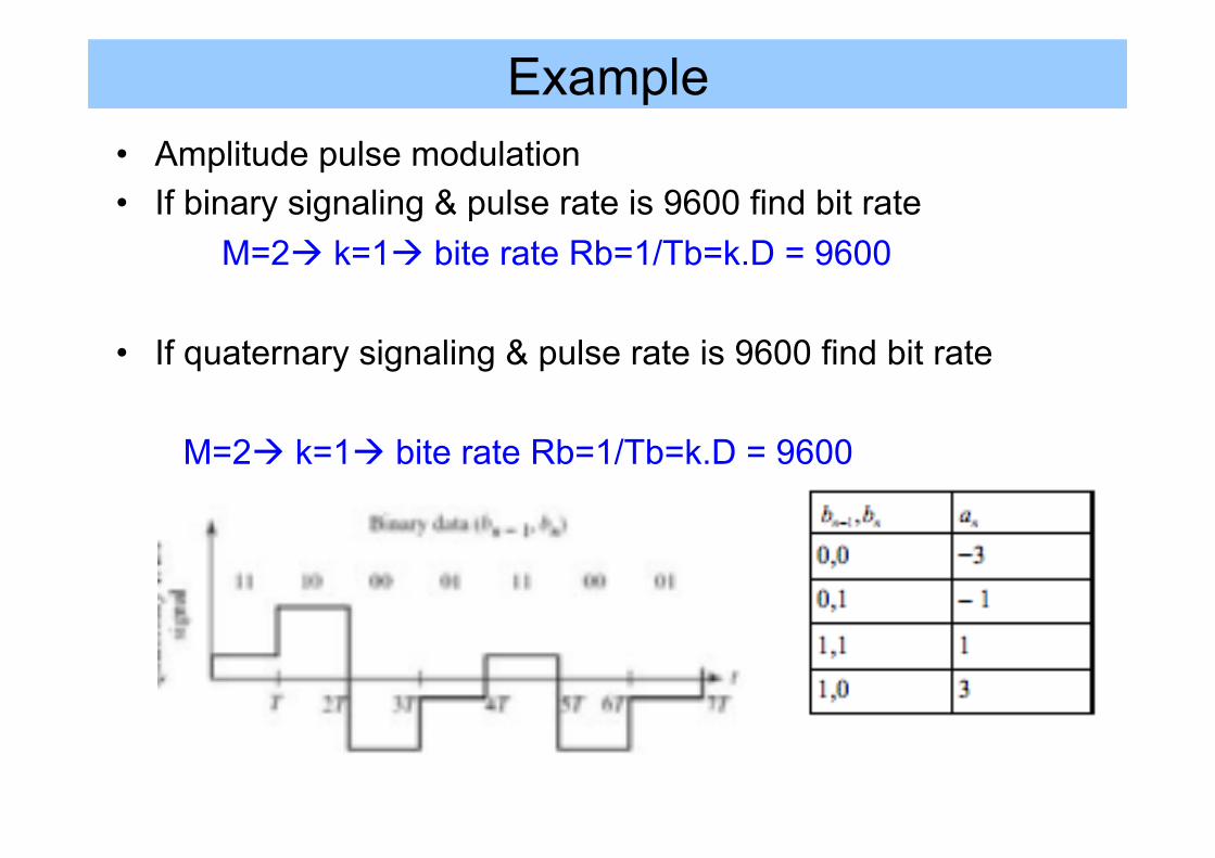
Example • Amplitude pulse modulation • If binary signaling & pulse rate is 9600 find bit rate M=2à k=1à bite rate Rb=1/Tb=k.D = 9600 • If quaternary signaling & pulse rate is 9600 find bit rate
M=2à k=1à bite rate Rb=1/Tb=k.D = 9600
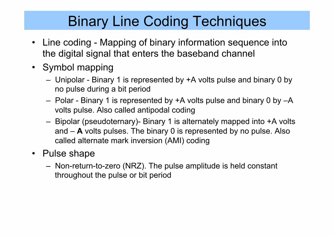
Binary Line Coding Techniques • Line coding - Mapping of binary information sequence into
the digital signal that enters the baseband channel • Symbol mapping
– Unipolar - Binary 1 is represented by +A volts pulse and binary 0 by no pulse during a bit period
– Polar - Binary 1 is represented by +A volts pulse and binary 0 by –A volts pulse. Also called antipodal coding
– Bipolar (pseudoternary)- Binary 1 is alternately mapped into +A volts and – A volts pulses. The binary 0 is represented by no pulse. Also called alternate mark inversion (AMI) coding
• Pulse shape – Non-return-to-zero (NRZ). The pulse amplitude is held constant
throughout the pulse or bit period
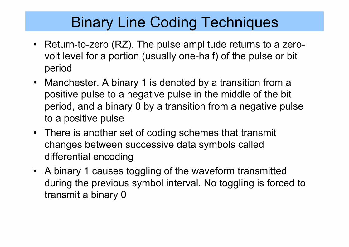
Binary Line Coding Techniques • Return-to-zero (RZ). The pulse amplitude returns to a zero-
volt level for a portion (usually one-half) of the pulse or bit period
• Manchester. A binary 1 is denoted by a transition from a positive pulse to a negative pulse in the middle of the bit period, and a binary 0 by a transition from a negative pulse to a positive pulse
• There is another set of coding schemes that transmit changes between successive data symbols called differential encoding
• A binary 1 causes toggling of the waveform transmitted during the previous symbol interval. No toggling is forced to transmit a binary 0
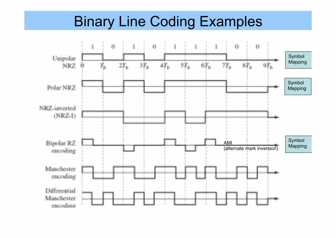
Binary Line Coding Examples
Symbol Mapping
Symbol Mapping
Symbol Mapping
AMI (alternate mark inversion)
Which Line Coding? • How do we know which line coding to choose? • Depends on a number of factors:
– How to deal with long stream of 1’s and 0’s (low frequency content) – Spectral characteristics – how much cross-talk or roll-off – BW Efficiency – what is the bit rate when BW is limited – Error detection capacity – Power efficiency - how much power is required to send the data
We look at several key parameters for each line coding: • Power Spectral Density • Bandwidth • Bit rate
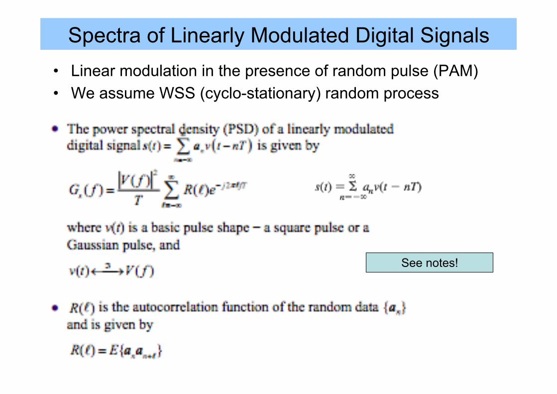
Spectra of Linearly Modulated Digital Signals • Linear modulation in the presence of random pulse (PAM) • We assume WSS (cyclo-stationary) random process
See notes!
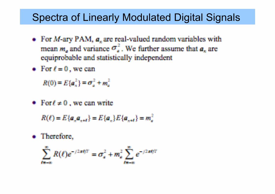
Spectra of Linearly Modulated Digital Signals
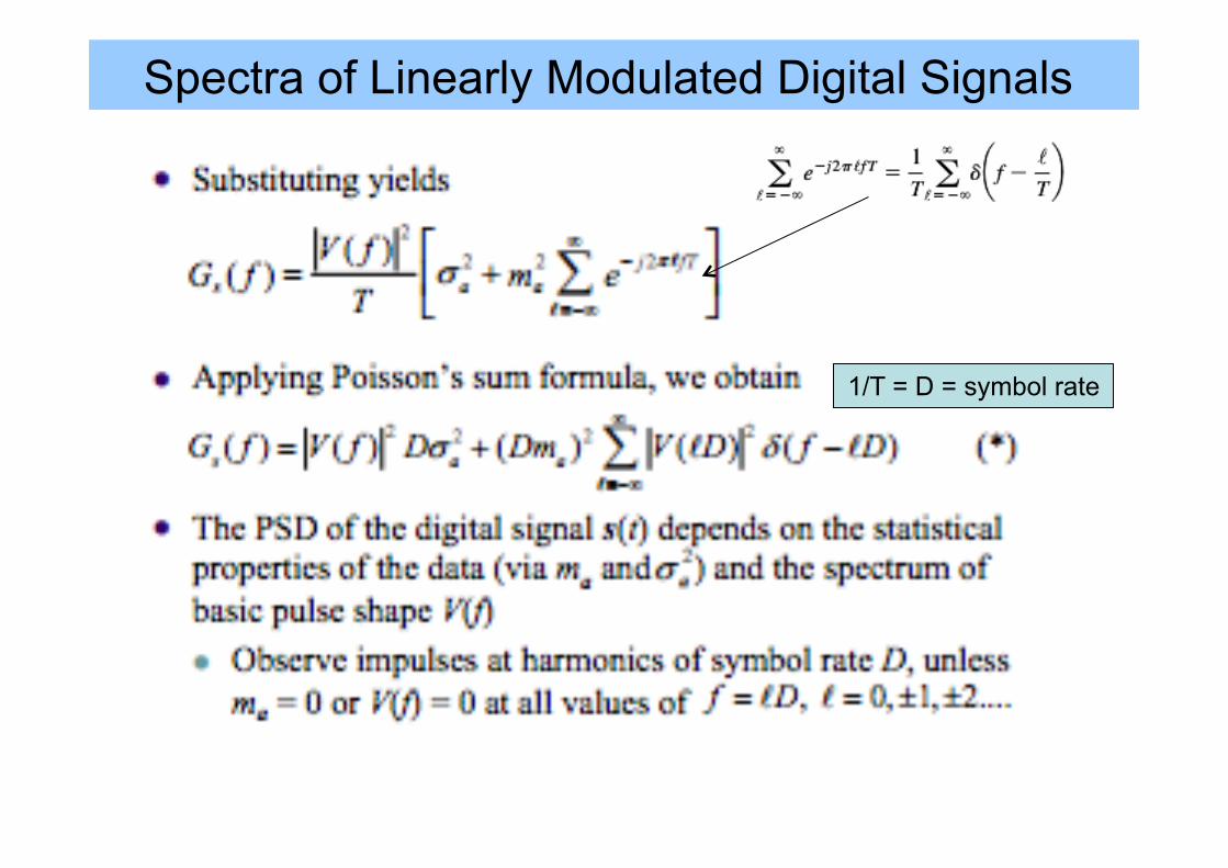
Spectra of Linearly Modulated Digital Signals
1/T = D = symbol rate
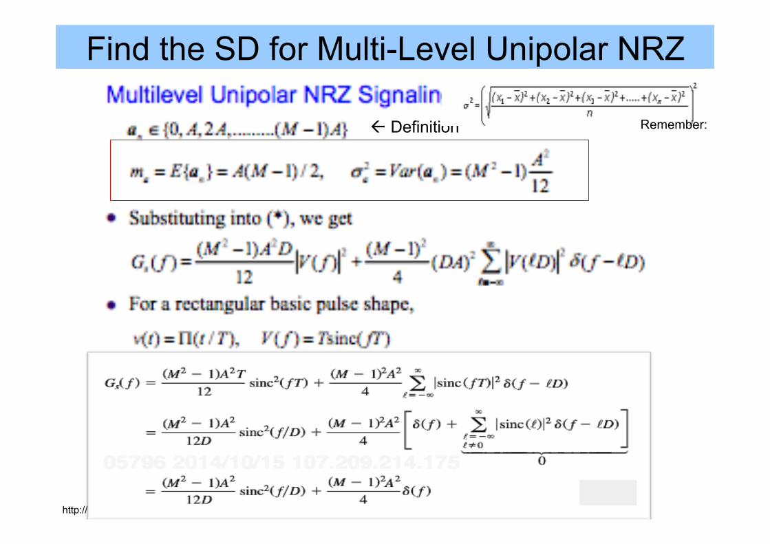
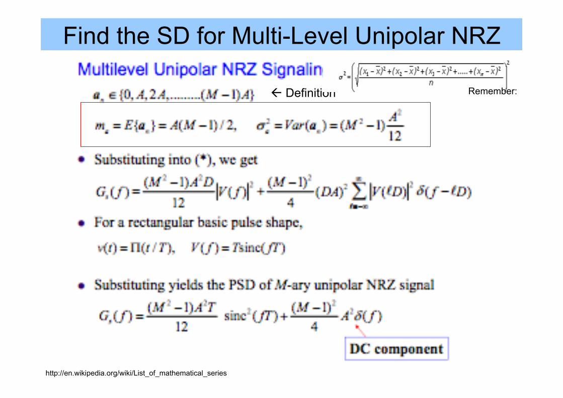
Find the SD for Multi-Level Unipolar NRZ
ß Definition
http://en.wikipedia.org/wiki/List_of_mathematical_series
Remember:
Find the SD for Multi-Level Unipolar NRZ
ß Definition
http://en.wikipedia.org/wiki/List_of_mathematical_series
Remember:
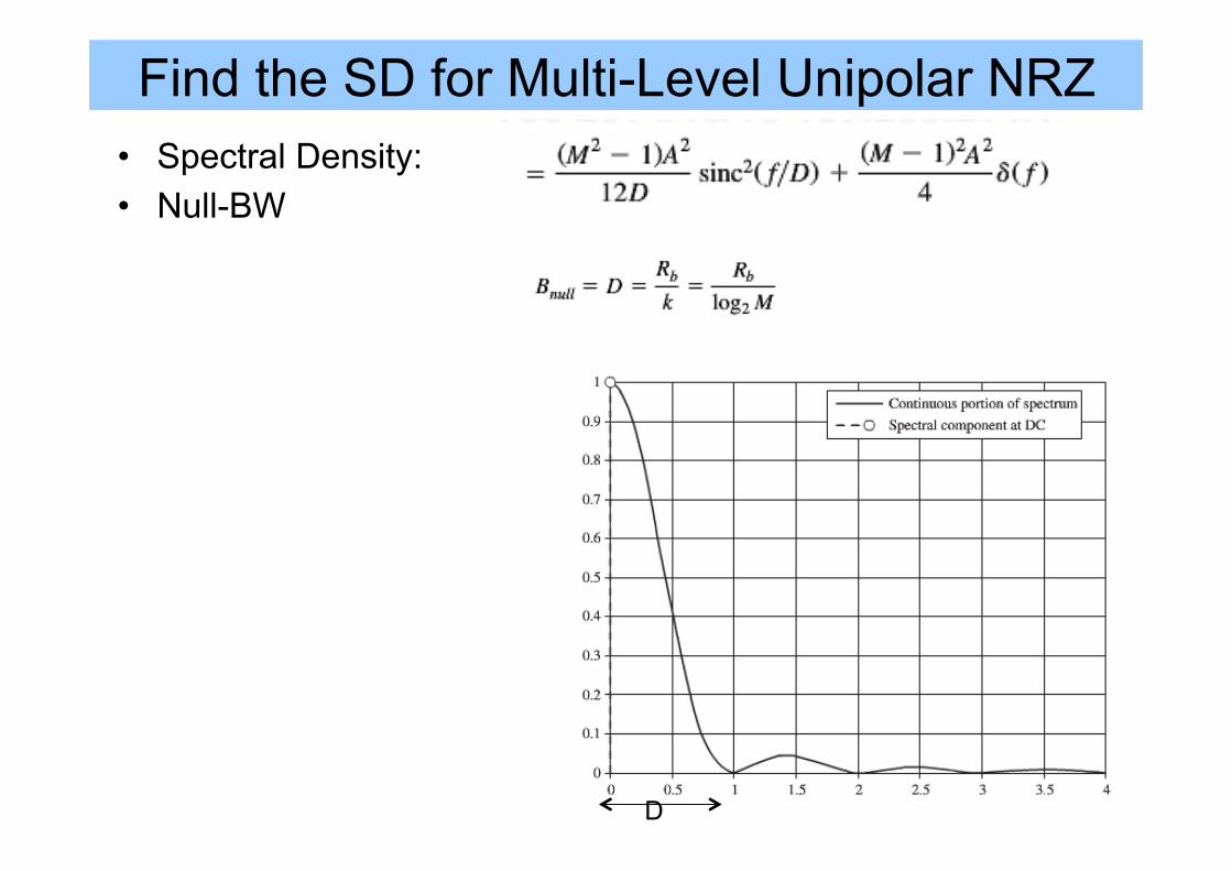
Find the SD for Multi-Level Unipolar NRZ • Spectral Density: • Null-BW
D
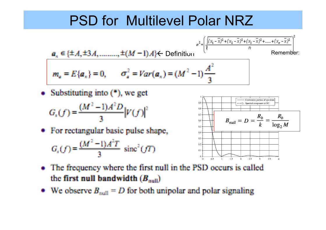
PSD for Multilevel Polar NRZ
ß Definition Remember:
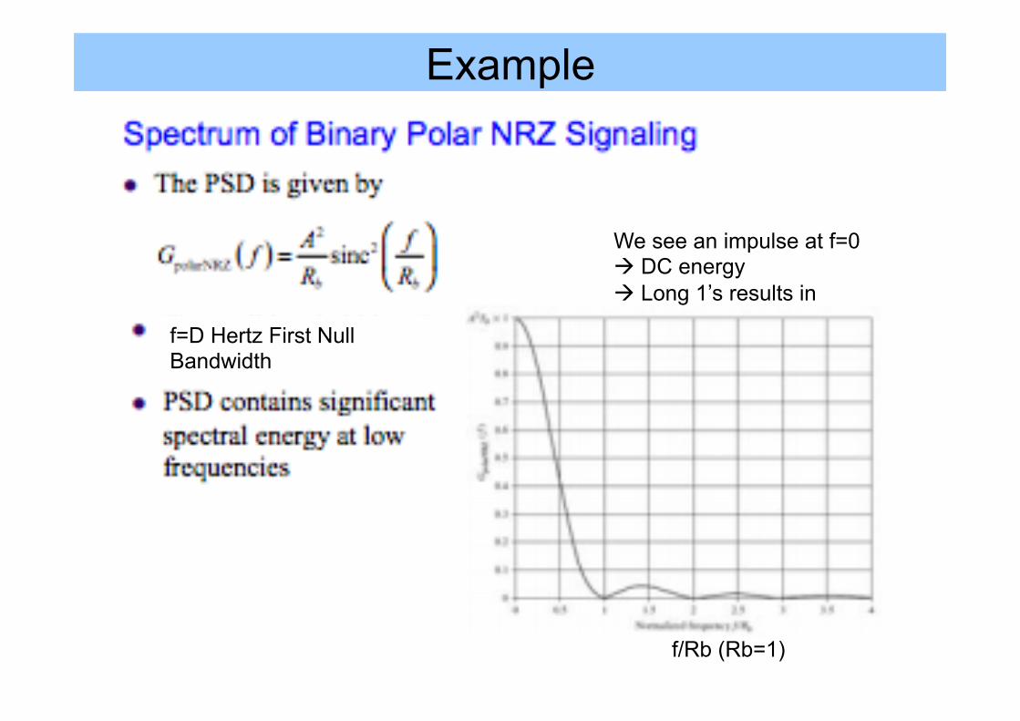
Example
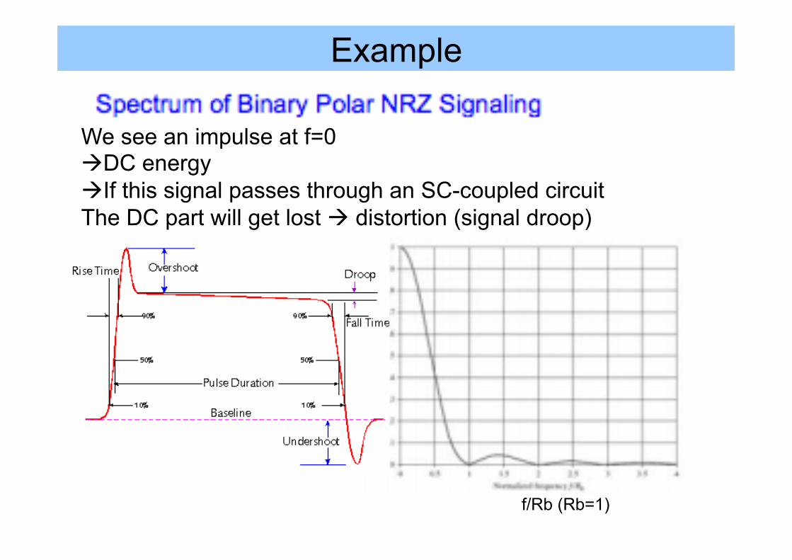
f/Rb (Rb=1)
f=D Hertz First Null Bandwidth
We see an impulse at f=0 à DC energy à Long 1’s results in
Example
f/Rb (Rb=1)
f=D Hertz First Null Bandwidth
We see an impulse at f=0 à DC energy à If this signal passes through an SC-coupled circuit The DC part will get lost à distortion (signal droop)
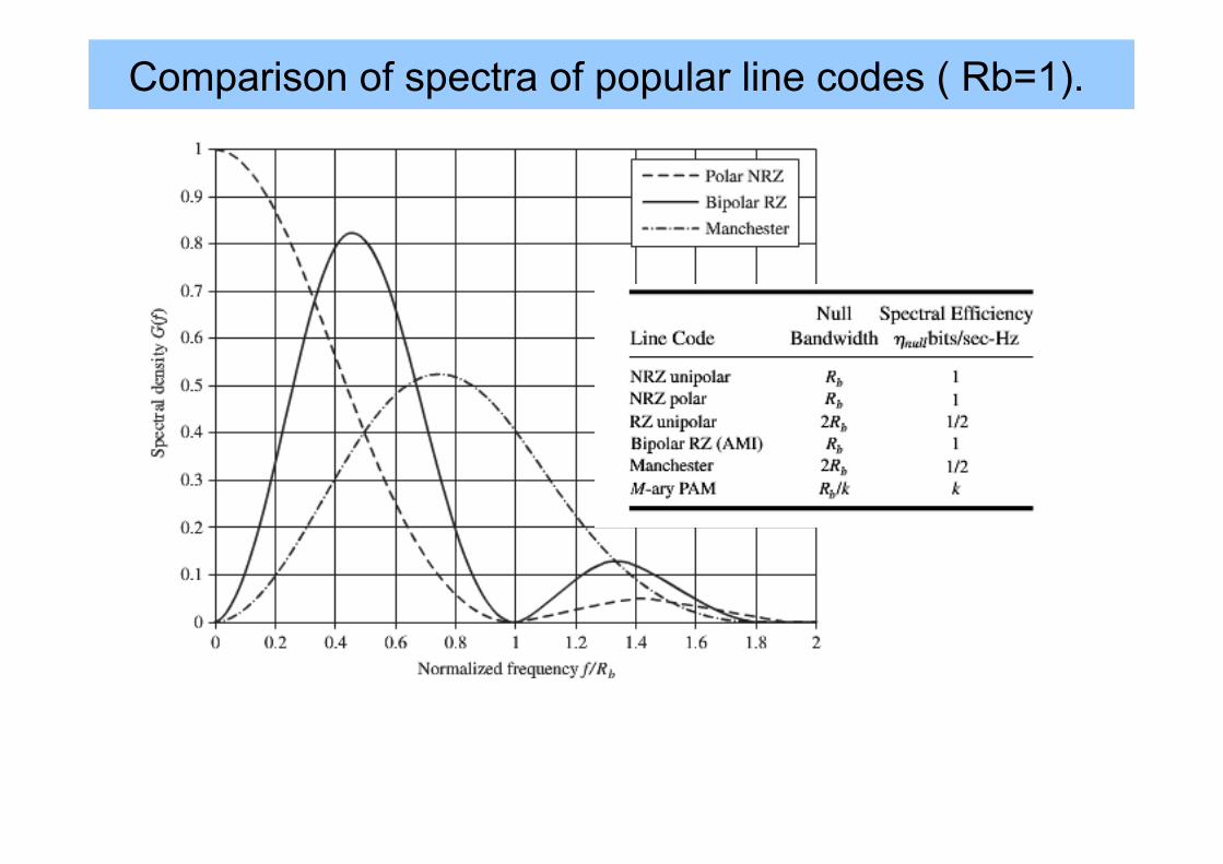
Comparison of spectra of popular line codes ( Rb=1).
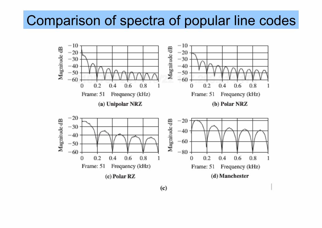
Comparison of spectra of popular line codes
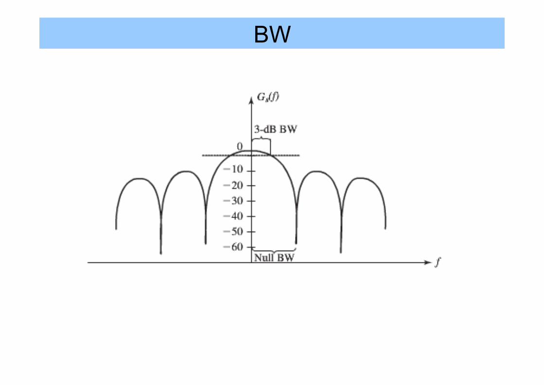
BW
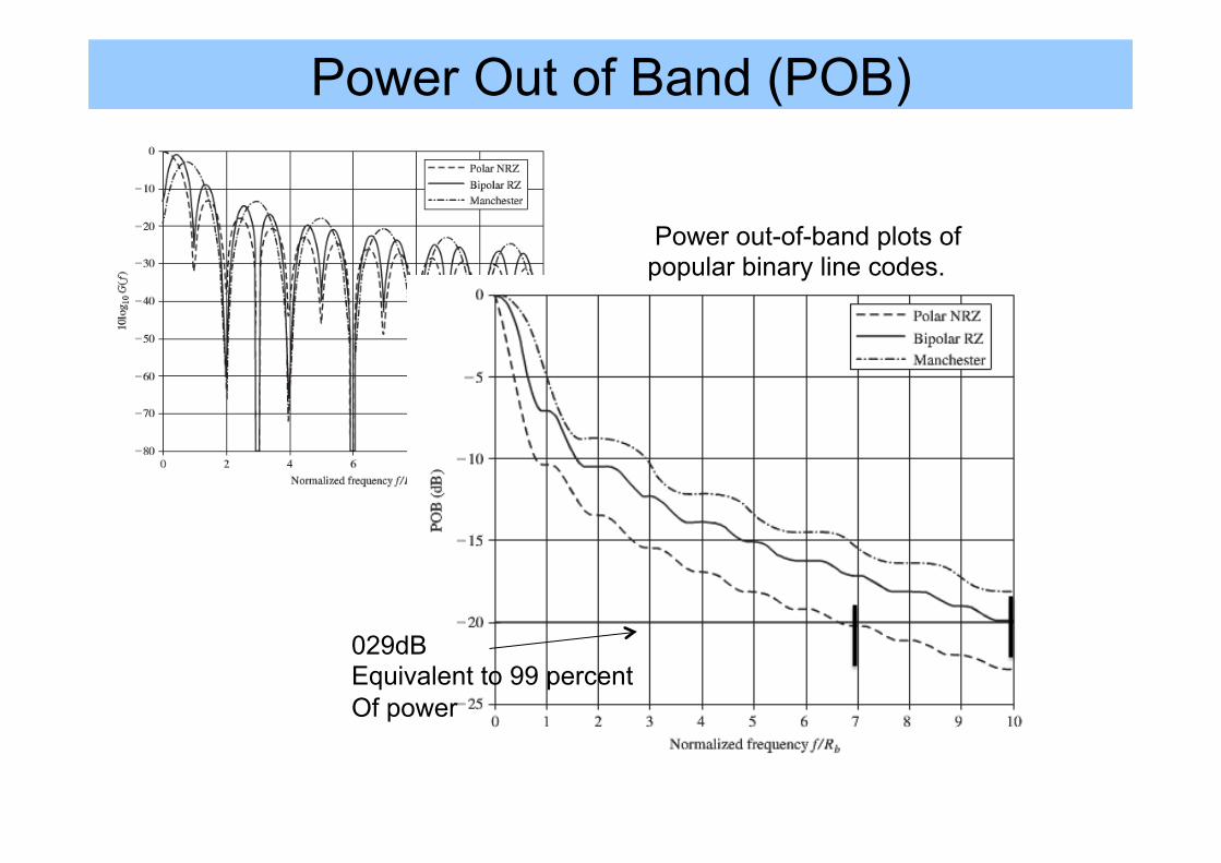
Power Out of Band (POB)
Power out-of-band plots of popular binary line codes.
029dB Equivalent to 99 percent Of power
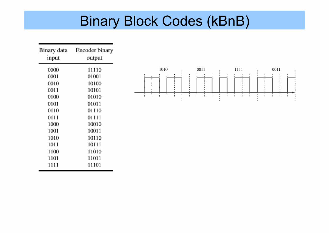
Binary Block Codes (kBnB)
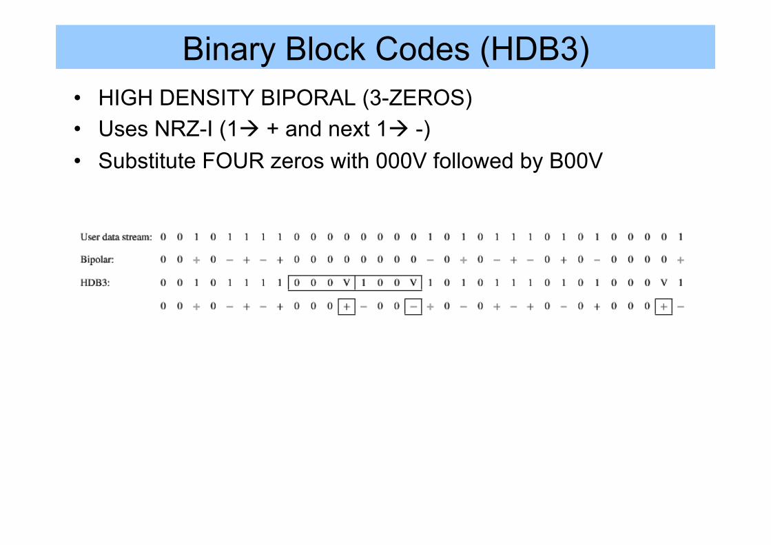
Binary Block Codes (HDB3) • HIGH DENSITY BIPORAL (3-ZEROS) • Uses NRZ-I (1à + and next 1à -) • Substitute FOUR zeros with 000V followed by B00V

References • Leon W. Couch II, Digital and Analog Communication
Systems, 8th edition, Pearson / Prentice, Chapter 6 • "M. F. Mesiya, ”Contemporary Communication Systems”,
1st ed./2012, 978-0-07-. 338036-0, McGraw Hill. Chapter 9