digital controller for a small vtol...
TRANSCRIPT

Digital Controller for a Small VTOL UAV
Gregory Kravit
6.111 Fall 2014
iFlight (450mm) ARF
• 4x1000Kv DC motors
• 30A ESCs
• Mass <1.5 kg
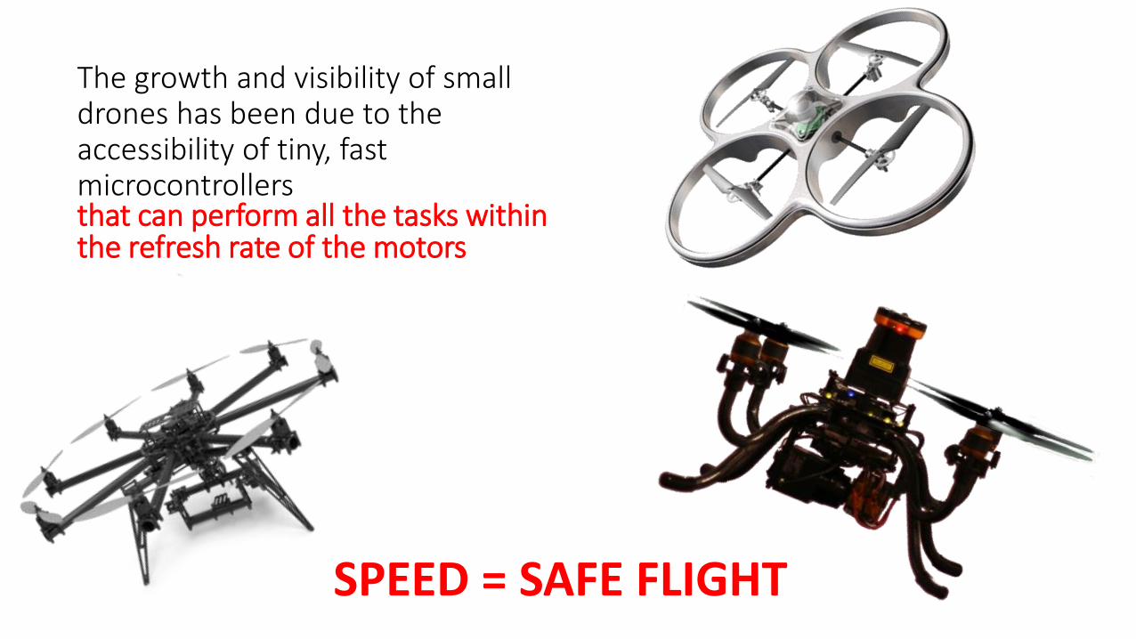
The growth and visibility of small drones has been due to the accessibility of tiny, fast microcontrollers that can perform all the tasks within the refresh rate of the motors
SPEED = SAFE FLIGHT

4 Motors + ESCs*
Exploiting Parallelism in Quadcopter Control
Sensors
*ESC = Electronic Speed Controller
FPGA

Project Goals
1. Design and implement a quadcopter control system that
• Stabilizes the UAV
• Holds a specific altitude
2. Integrate sensors to read current aircraft states• IMU (Inertial Measurement Unit)-> accelerometer, gyroscope, sensor fusion
• Ultrasonic Sensor
3. Demonstrate safe, stable flight in the lab environment

Control System Block Diagram

FPGA Module Diagram
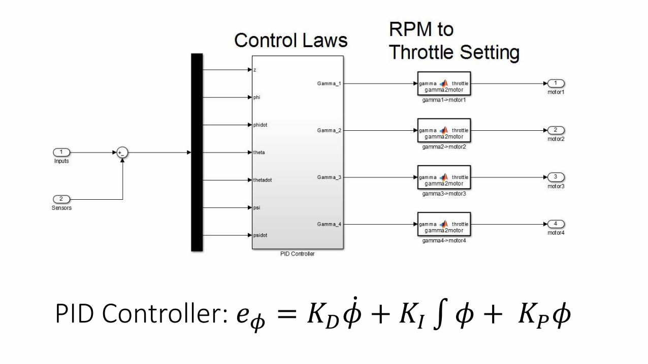
PID Controller: 𝑒𝜙 = 𝐾𝐷 𝜙 + 𝐾𝐼 𝜙 + 𝐾𝑃𝜙

FPGA Module Summary
• Flight Control Module• PID arithmetic
• Map RPM to throttle setting
• Control Inputs
• Motor Controller• Throttle Setting to PWM pulse
length
• PWM pulse out
• IMU Sensor Reader• I2C Master
• Convert quaternions to angles
• Initialize IMU sensor
• Altitude Range Sensor• Send start signal
• Counter for signal time
• Receive signal echo
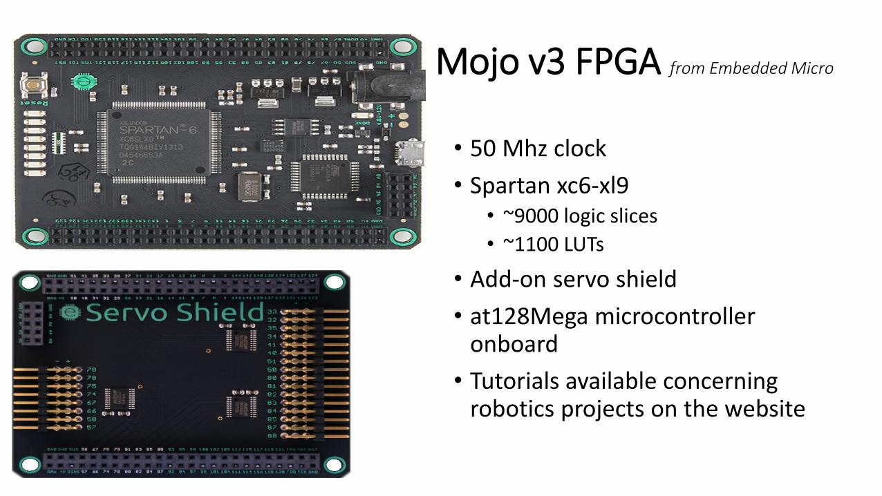
Mojo v3 FPGA from Embedded Micro
• 50 Mhz clock
• Spartan xc6-xl9• ~9000 logic slices
• ~1100 LUTs
• Add-on servo shield
• at128Mega microcontroller onboard
• Tutorials available concerning robotics projects on the website

Systems Integration Tasks
• Build UAV from Almost-Ready-to-Fly (ARF) kit
• Tether the power source using speaker cable and PC ATX power supply
• Integrate sensors onto the UAV
• Tune PID parameters for stabilized flight

Expected Issues
• Limited number of LUTs on the FPGA• SOLUTION: Exploit low refresh rate (~400hz) and use limited logic slice
arithmetic algorithms as well as onboard DSPs
• Tuning PID can be difficult• SOLUTION: Model quadrotor and controllers in MATLAB simulation
• IMU (MPU-6050) is difficult to interface without closed-source developer software• SOLUTION: Translate open source Arduino code to work as FPGA state
machines

TimelineWeek Nov 1-Nov 7 : Order Parts
Test Motors and ESCs
Model quadrotor in MATLAB and determine PID controller equations
Week Nov 8-Nov 14 : Design and implement
o Motor controller
o Ground Control Station Input
Build quadrotor
Get systems integrated begin testingWeek Nov 15-Nov 21 : Design and implement
o Sensor Modules
o Flight Controller
Get systems integrated
o test all modules
o test working quadrotor
Tune PID controller through testingWeeks Nov 24-Dec 5 : Finish the system, get everything working
Write final report

Questions and Comments

Appendix
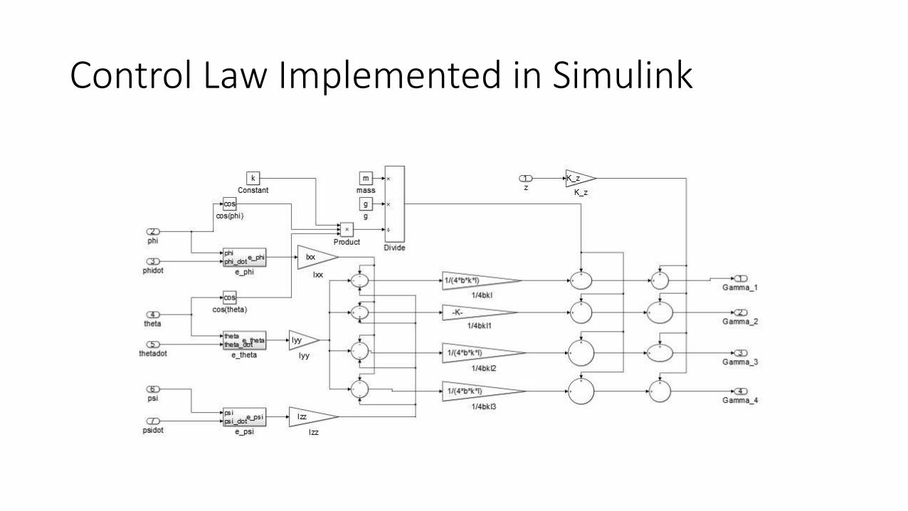
Control Law Implemented in Simulink