digital data transmission dte-dce interface modems …csnotes.upm.edu.my/kelasmaya/web.nsf... ·...
TRANSCRIPT
Lecture notes SKR 3200 17 August 2009
Idawaty Ahmad 1
CHAPTER 4TRANSMISSION OF DIGITAL DATA
8/17/200TRANSMISSION OF DIGITAL DATAINTERFACE AND MODEM
Digital Data TransmissionDTE-DCE InterfaceModems
09Idaw
aty Ahm
ad : idawaty@ode s @
fsktm.upm
.edu.my
1
INTRODUCTION
How do we encoded data from the generatingdevice (PC) to the next device (modem) before it is
8/17/2009
device (PC) to the next device (modem) before it issent over a communication link (telephone line)?The answer is interfaceinterface – a bundle of wires, a sortof mini-communication linkBecause an interface links two devices notnecessarily made by the same manufacturer, itscharacteristics must be defined and standardsstandards mustmust
Idawaty A
hmad : idaw
aty@fsk
bebe establishedestablished..The characteristics: mechanical spec, electricalspec, functional spec.
2
ktm.upm
.edu.my
Lecture notes SKR 3200 17 August 2009
Idawaty Ahmad 2
DIGITAL DATA TRANSMISSION8/17/2009
Transmission of data wiring data streamDo we send one bit at a time, or do we group bitsDo we send one bit at a time, or do we group bitsinto larger groups, if so how?The transmission of binary data across a link can beaccomplished either in parallel mode or serialmode.In parallel mode – multiple bits are sent with eachclock pulse
3
In serial mode – one bit is sent with each clockpulse. Occurs in two ways: synchronous andasynchronous.
PARALLEL TRANSMISSION
Binary data (consist of 1s,0s) may be organized intogroups of n bits each.
8/17/2009g pConcepts: “use nn wires to send nn bits at one time”Each bit has its own wire, and all n bits one groupcan be transmitted with each clock pulse from onedevice to another.Advantage:
Speed – increase transfer speed by factor of n over serialDisadvantage:
Cost – requires n communication lines (wires) just totransmit the data stream.
4
Lecture notes SKR 3200 17 August 2009
Idawaty Ahmad 3
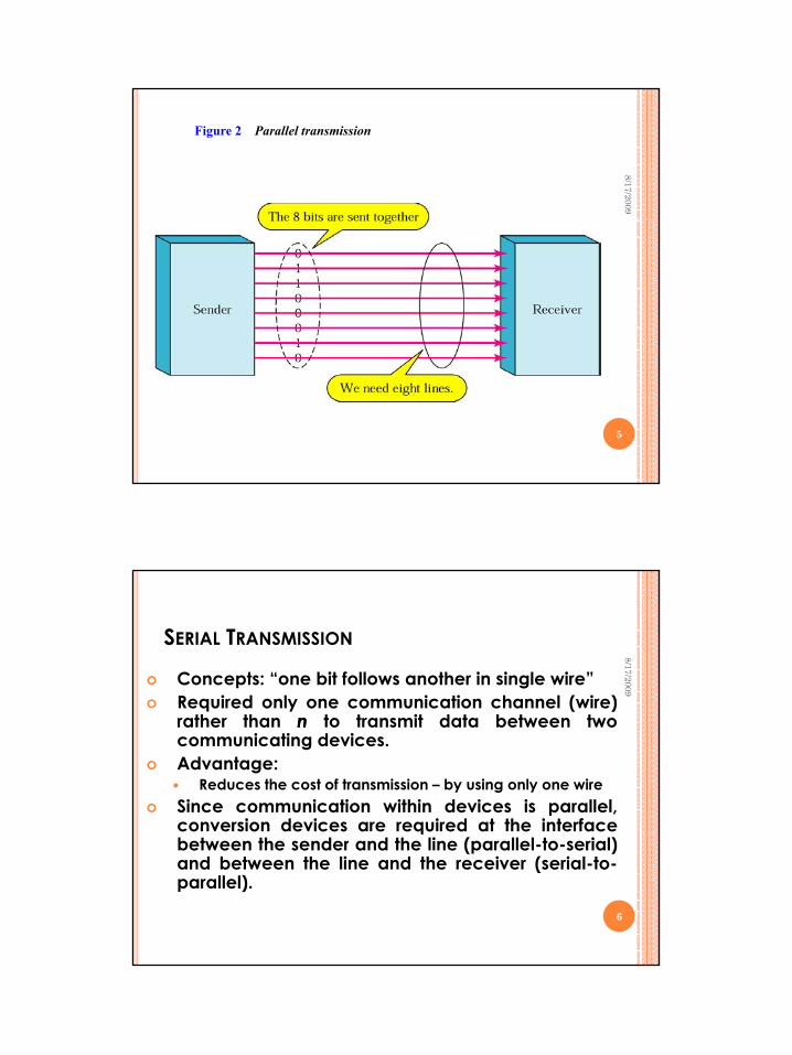
Figure 2 Parallel transmission
8/17/2009
5
SERIAL TRANSMISSION
Concepts: “one bit follows another in single wire”Required only one communication channel (wire)
8/17/2009
Required only one communication channel (wire)rather than nn to transmit data between twocommunicating devices.Advantage:
Reduces the cost of transmission – by using only one wireSince communication within devices is parallel,conversion devices are required at the interfaceqbetween the sender and the line (parallel-to-serial)and between the line and the receiver (serial-to-parallel).
6
Lecture notes SKR 3200 17 August 2009
Idawaty Ahmad 4
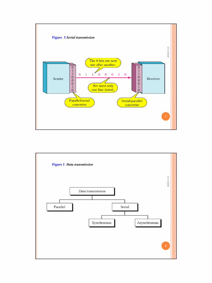
Figure 3 Serial transmission
8/17/2009
7
Figure 1 Data transmission
8/17/2009
8
Lecture notes SKR 3200 17 August 2009
Idawaty Ahmad 5
SERIAL TRANSMISSION: ASYNCHRONOUSTRANSMISSION
Timing of a signal is unimportant.Instead, information is received and translated by agreed-upon
tt
8/17/2009
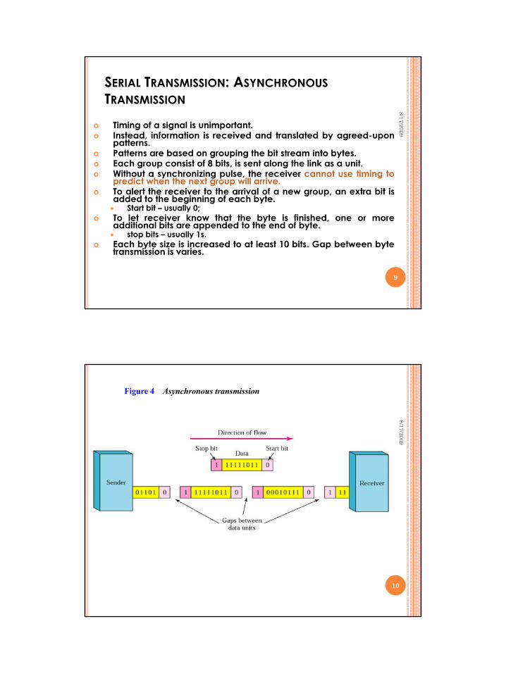
patterns.Patterns are based on grouping the bit stream into bytes.Each group consist of 8 bits, is sent along the link as a unit.Without a synchronizing pulse, the receiver cannot use timing topredict when the next group will arrive.To alert the receiver to the arrival of a new group, an extra bit isadded to the beginning of each byte.
Start bit – usually 0;To let receiver know that the byte is finished, one or moreadditional bits are appended to the end of byteadditional bits are appended to the end of byte.
stop bits – usually 1s.Each byte size is increased to at least 10 bits. Gap between bytetransmission is varies.
9
Figure 4 Asynchronous transmission
8/17/2009
10
Lecture notes SKR 3200 17 August 2009
Idawaty Ahmad 6
SERIAL TRANSMISSION: ASYNCHRONOUSTRANSMISSION
In asynchronous transmission, we send 1 start bit (0) at the beginning and 1 or more stop bits (1s) at the end of each byte There may be a gap between each byte
8/17/2009
byte. There may be a gap between each byte.Called asynchronous because, at the byte level, sender andreceiver do not have to be synchronized.But within each byte, the receiver must still be synchronizedwith the incoming bit stream.When the receiver detects a start bit, it sets a timer and beginscounting bits as they come in. After n bits, the receiver looksfor a stop bit.The addition of stop and start bits and the insertion of gapsThe addition of stop and start bits and the insertion of gapsinto the bit stream make asynchronous transmission slow.Cheap and effective – choice for low speed communicationE.g: Connection of a terminal to a computer.
11
SERIAL TRANSMISSION: ASYNCHRONOUSTRANSMISSION
I h i i d 1 biI h i i d 1 bi
8/17/2009
Asynchronous here means “asynchronous at theAsynchronous here means “asynchronous at the
In asynchronous transmission, we send 1 start bit In asynchronous transmission, we send 1 start bit (0) at the beginning and 1 or more stop bits (1s) at (0) at the beginning and 1 or more stop bits (1s) at the end of each byte. There may be a gap between the end of each byte. There may be a gap between
each byte.each byte.
Asynchronous here means asynchronous at the Asynchronous here means asynchronous at the byte level,” but the bits are still synchronized; byte level,” but the bits are still synchronized;
their durations are the same.their durations are the same.12
Lecture notes SKR 3200 17 August 2009
Idawaty Ahmad 7
SERIAL TRANSMISSION: SYNCHRONOUSTRANSMISSION
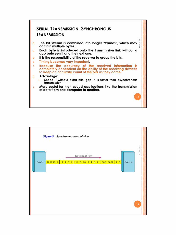
The bit stream is combined into longer “frames”, which maycontain multiple bytes.
i i i i i i
8/17/2009
Each byte is introduced onto the transmission link without agap between it and the next one.It is the responsibility of the receiver to group the bits.Timing becomes very important.Because the accuracy of the received information iscompletely dependent on the ability of the receiving devicesto keep an accurate count of the bits as they come.Advantage:
Speed – without extra bits, gap, it is faster than asynchronoustransmission
More useful for high-speed applications like the transmissionof data from one computer to another.
13
Figure 5 Synchronous transmission
8/17/2009
14
Lecture notes SKR 3200 17 August 2009
Idawaty Ahmad 8
SERIAL TRANSMISSION: SYNCHRONOUSTRANSMISSION
8/17/2009
In synchronous transmission, In synchronous transmission, we send bits one after another without start/stop we send bits one after another without start/stop
bits or gaps. bits or gaps. It is the responsibility of the receiver to group the It is the responsibility of the receiver to group the
bits.bits.
15
DTE-DCE INTERFACE
8/17/2009
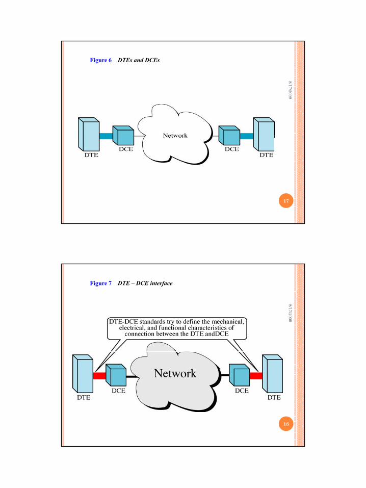
Data Terminal Equipment (DTE) and Data Circuit-TerminatingEquipment (DCE)There 4 basic functional units involved in the communicationdata:
DTE and DCE at one end and DTE and DCE at the other andThe DTE generates the data and passes them to a DCE.The DCE converts the signal to a format appropriate to thetransmission medium and introduces it onto the network link.When the signal arrives at the receiving end this process is
16
When the signal arrives at the receiving end, this process isreversed.
Lecture notes SKR 3200 17 August 2009
Idawaty Ahmad 9
Figure 6 DTEs and DCEs
8/17/2009
17
Figure 7 DTE – DCE interface
8/17/2009
18
Lecture notes SKR 3200 17 August 2009
Idawaty Ahmad 10
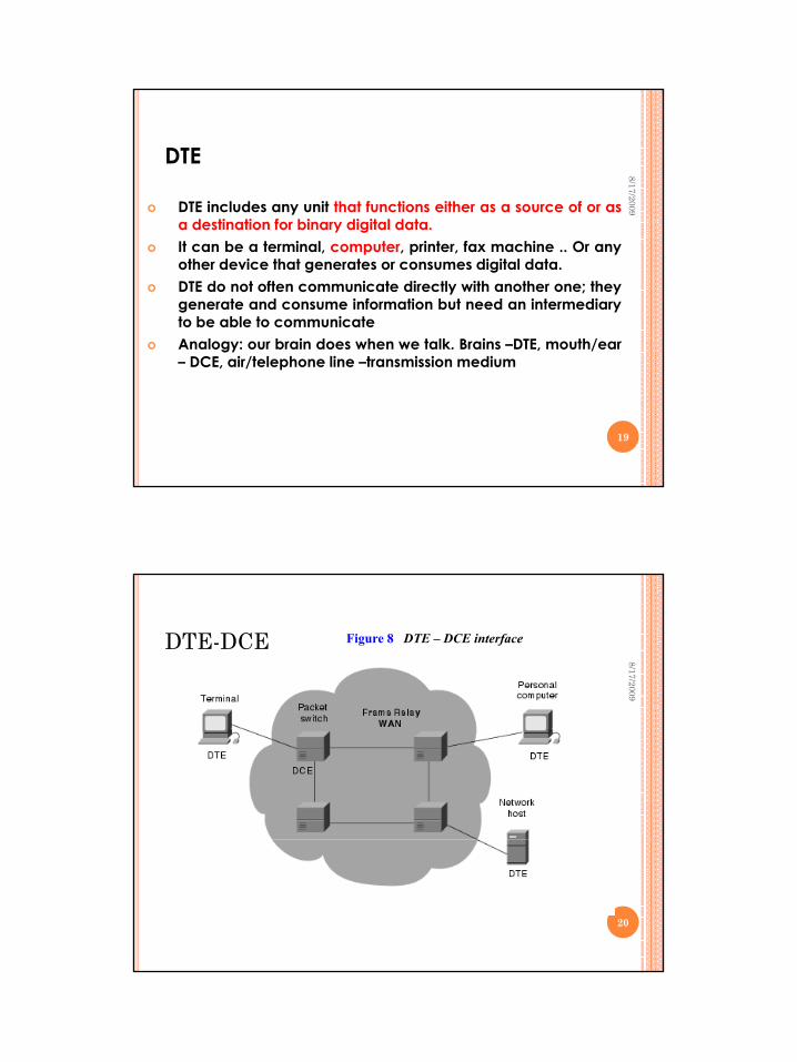
DTE
DTE includes any unit that functions either as a source of or asd ti ti f bi di it l d t
8/17/2009
a destination for binary digital data.It can be a terminal, computer, printer, fax machine .. Or anyother device that generates or consumes digital data.DTE do not often communicate directly with another one; theygenerate and consume information but need an intermediaryto be able to communicateAnalogy: our brain does when we talk. Brains –DTE, mouth/ear– DCE, air/telephone line –transmission medium
19
DTE-DCE
8/17/2009
Figure 8 DTE – DCE interface
20
Lecture notes SKR 3200 17 August 2009
Idawaty Ahmad 11
DTE-DCE8/17/2009
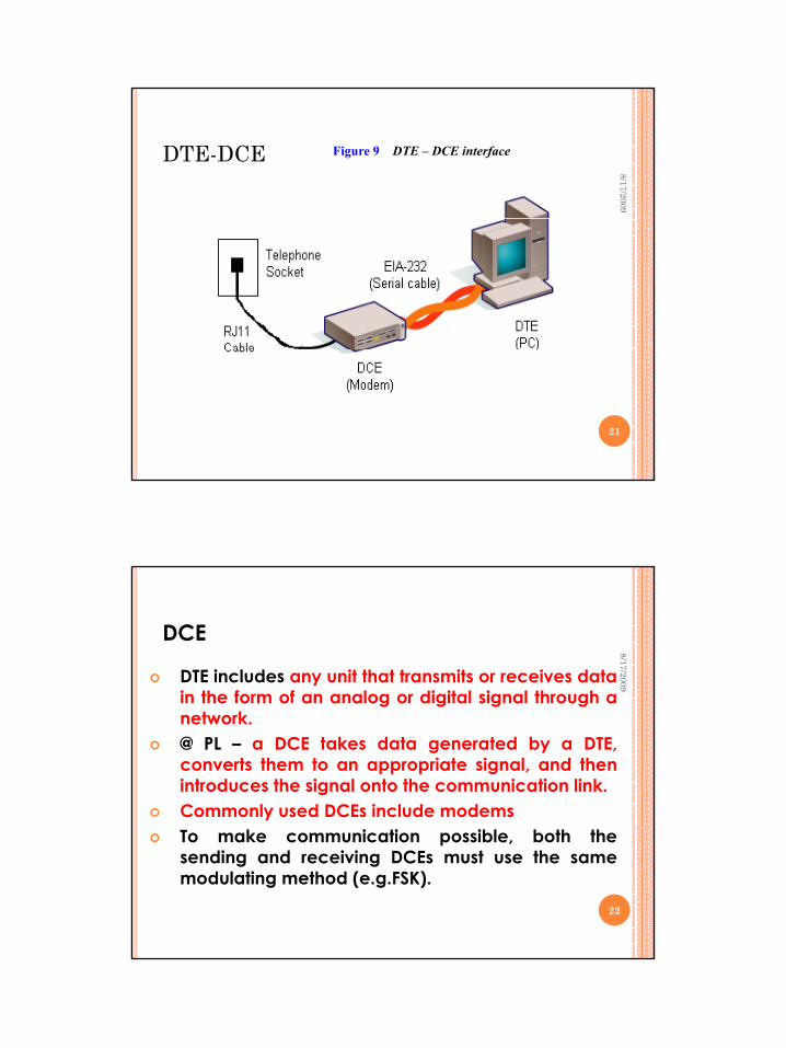
Figure 9 DTE – DCE interface
21
DCE
DTE includes any unit that transmits or receives datain the form of an analog or digital signal through a
8/17/2009
in the form of an analog or digital signal through anetwork.@ PL – a DCE takes data generated by a DTE,converts them to an appropriate signal, and thenintroduces the signal onto the communication link.Commonly used DCEs include modemsTo make communication possible, both thesending and receiving DCEs must use the samemodulating method (e.g.FSK).
22
Lecture notes SKR 3200 17 August 2009
Idawaty Ahmad 12
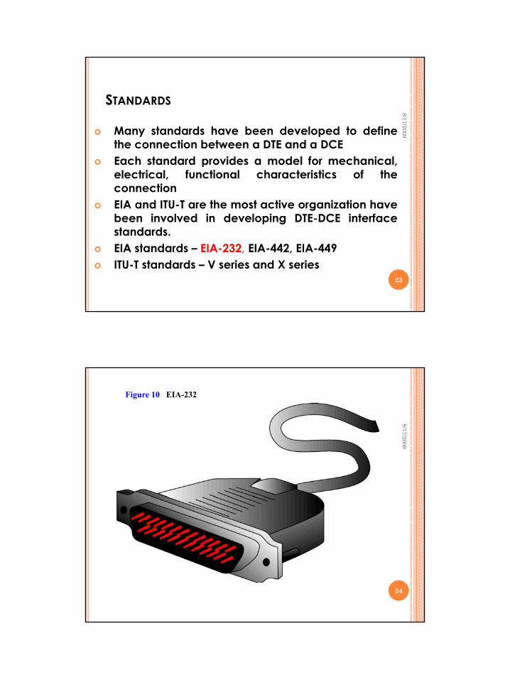
STANDARDS
Many standards have been developed to defineth ti b t DTE d DCE
8/17/2009
the connection between a DTE and a DCEEach standard provides a model for mechanical,electrical, functional characteristics of theconnectionEIA and ITU-T are the most active organization havebeen involved in developing DTE-DCE interfacestandards.EIA standards – EIA-232, EIA-442, EIA-449ITU-T standards – V series and X series
23
Figure 10 EIA-232
8/17/2009
24
Lecture notes SKR 3200 17 August 2009
Idawaty Ahmad 13
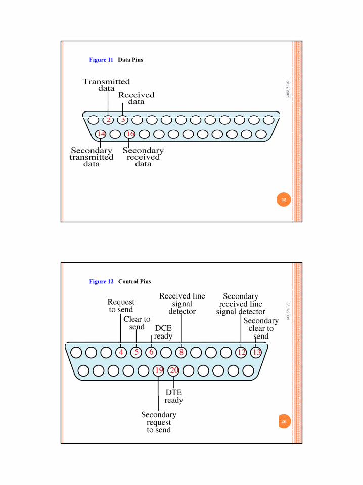
Figure 11 Data Pins
8/17/2009
25
Figure 12 Control Pins
8/17/2009
26
Lecture notes SKR 3200 17 August 2009
Idawaty Ahmad 14
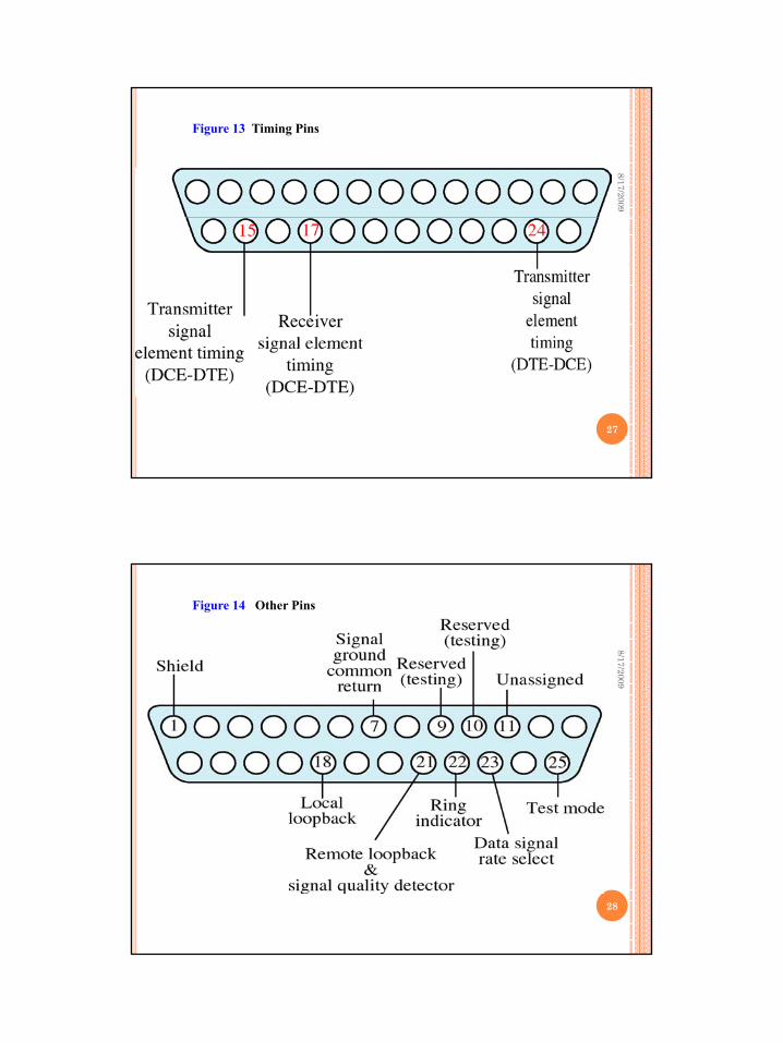
Figure 13 Timing Pins
8/17/2009
27
Figure 14 Other Pins
8/17/2009
28
Lecture notes SKR 3200 17 August 2009
Idawaty Ahmad 15
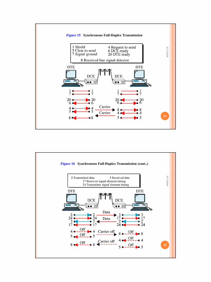
Figure 15 Synchronous Full-Duplex Transmission
8/17/2009
29
Figure 16 Synchronous Full-Duplex Transmission (cont..)
8/17/2009
30
Lecture notes SKR 3200 17 August 2009
Idawaty Ahmad 16
MODEMS
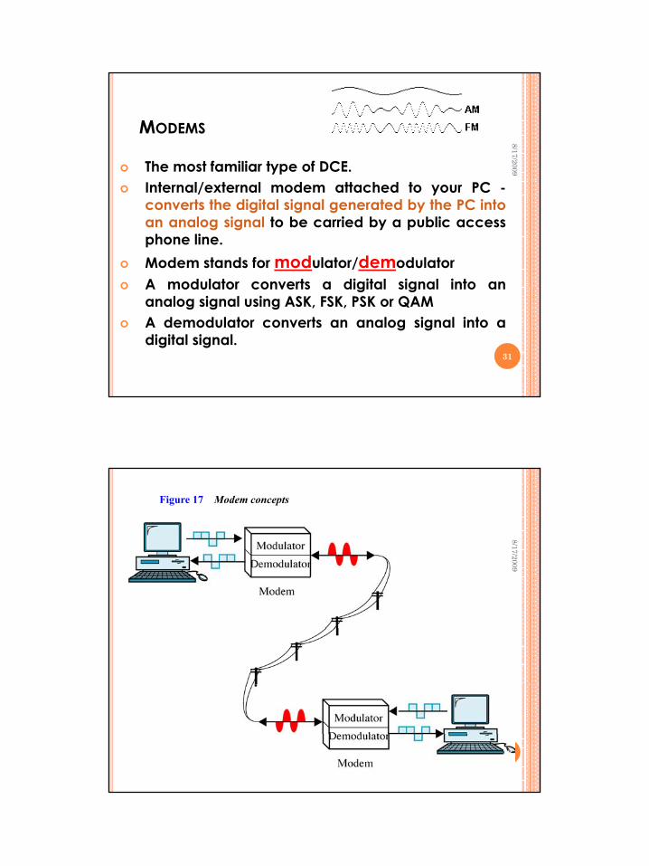
The most familiar type of DCE.
8/17/2009
Internal/external modem attached to your PC -converts the digital signal generated by the PC intoan analog signal to be carried by a public accessphone line.Modem stands for modulator/demodulatorA modulator converts a digital signal into anA modulator converts a digital signal into ananalog signal using ASK, FSK, PSK or QAMA demodulator converts an analog signal into adigital signal.
31
Figure 17 Modem concepts
8/17/2009
32
Lecture notes SKR 3200 17 August 2009
Idawaty Ahmad 17
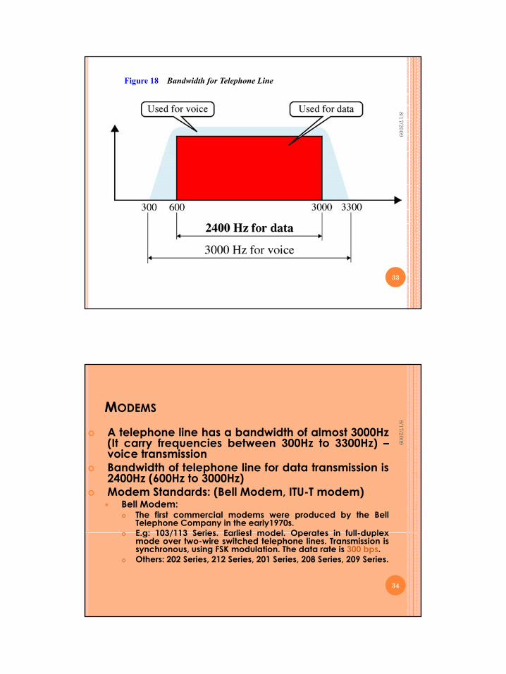
Figure 18 Bandwidth for Telephone Line
8/17/2009
33
MODEMS
8/17/2009
A telephone line has a bandwidth of almost 3000Hz(It carry frequencies between 300Hz to 3300Hz) –( y q )voice transmissionBandwidth of telephone line for data transmission is2400Hz (600Hz to 3000Hz)Modem Standards: (Bell Modem, ITU-T modem)
Bell Modem:The first commercial modems were produced by the BellTelephone Company in the early1970s.E g: 103/113 Series Earliest model Operates in full duplex
34
E.g: 103/113 Series. Earliest model. Operates in full-duplexmode over two-wire switched telephone lines. Transmission issynchronous, using FSK modulation. The data rate is 300 bps.Others: 202 Series, 212 Series, 201 Series, 208 Series, 209 Series.
Lecture notes SKR 3200 17 August 2009
Idawaty Ahmad 18
MODEMS
ITU-T Modem StandardsM f th t l d il bl
8/17/2009
Many of the most popular modems available arebased on standards published by the ITU-T.Can be divided into two groups: essentially equivalentto Bell series modems and those are not.E.g. of equivalent to Bell – V.21 similar to Bell modem103Others: V.22bis, V.32, V.32bis…
35
TRADITIONAL MODEMS AND 56K MODEMS
Traditional modems have a limitation on thed t t 33 6Kb
8/17/2009
data rate - max 33.6KbpsNew modem have a bit rate of 56,000 bps(called 5656KK modemmodem)
AsymmetricalDownloading (flow of data from the Internet Provider tothe PC) – a maximum of 56Kbps) pUploading (flow of data from the PC to the InternetProvider) - can be a maximum of 33.6 Kbps
36
Lecture notes SKR 3200 17 August 2009
Idawaty Ahmad 19
TRADITIONAL MODEMS
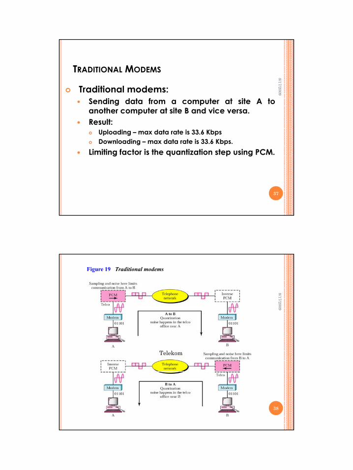
Traditional modems:
8/17/2009
Sending data from a computer at site A toanother computer at site B and vice versa.Result:
Uploading – max data rate is 33.6 KbpsDownloading – max data rate is 33.6 Kbps.
Limiting factor is the quantization step using PCM.
37
Figure 19 Traditional modems
8/17/2009
Telekom
38
Lecture notes SKR 3200 17 August 2009
Idawaty Ahmad 20
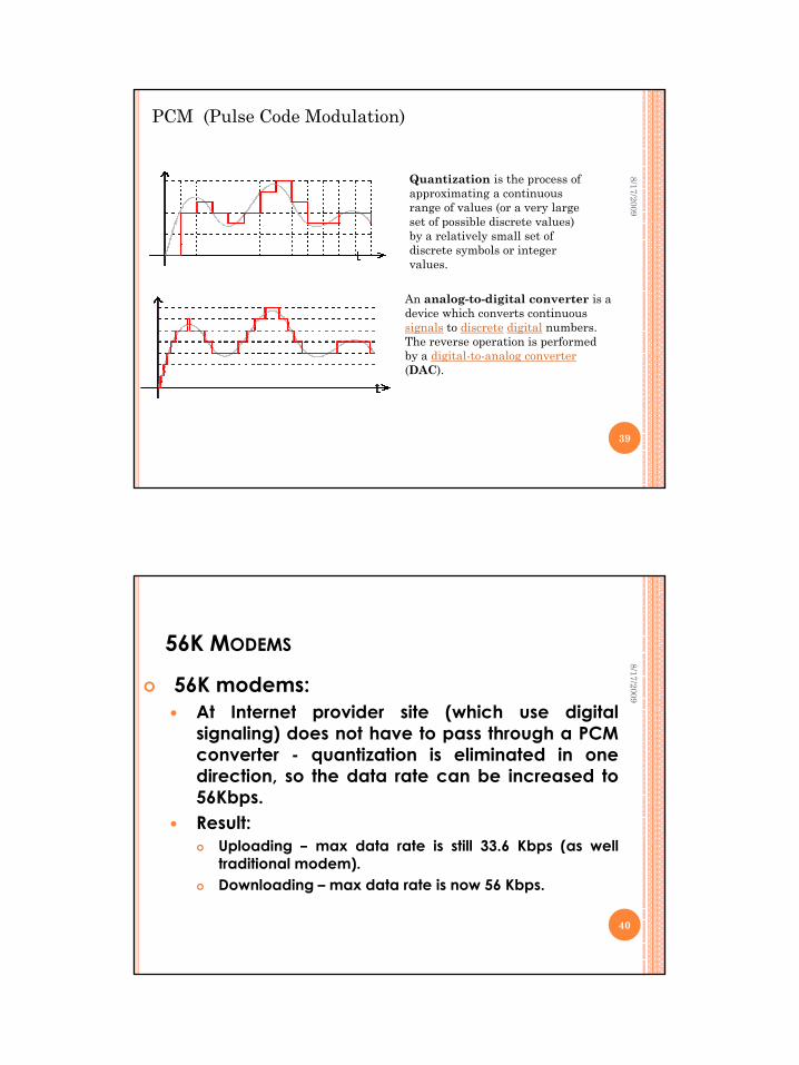
PCM (Pulse Code Modulation)
8/17/2009Quantization is the process of approximating a continuous range of values (or a very large set of possible discrete values) set of possible discrete values) by a relatively small set of discrete symbols or integer values.
An analog-to-digital converter is a device which converts continuous signals to discrete digital numbers. The reverse operation is performed by a digital to analog converter
39
by a digital-to-analog converter(DAC).
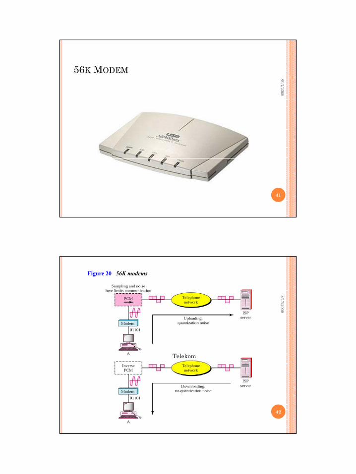
56K MODEMS
56K modems:At Internet provider site (which use digital
8/17/2009
At Internet provider site (which use digitalsignaling) does not have to pass through a PCMconverter - quantization is eliminated in onedirection, so the data rate can be increased to56Kbps.Result:
U l di d t t i till 33 6 Kb ( llUploading – max data rate is still 33.6 Kbps (as welltraditional modem).Downloading – max data rate is now 56 Kbps.
40
Lecture notes SKR 3200 17 August 2009
Idawaty Ahmad 21
56K MODEM8/17/2009
41
Figure 20 56K modems
8/17/2009
Telekom
42
Lecture notes SKR 3200 17 August 2009
Idawaty Ahmad 22
8/17/2009Idaw
aty Ahm
ad : Semester 2 :
43
2008/2009