digital factory technologies for robotic automation … · digital factory technologies for robotic...
TRANSCRIPT
Caggiano & Teti, Cogent Engineering (2018), 5: 1426676https://doi.org/10.1080/23311916.2018.1426676
MECHANICAL ENGINEERING | RESEARCH ARTICLE
Digital factory technologies for robotic automation and enhanced manufacturing cell designAlessandra Caggiano1,2* and Roberto Teti1,3
Abstract: The fourth industrial revolution is characterised by the increased use of digital tools, allowing for the virtual representation of a real production environment at different levels, from the entire production plant to a single machine or a specific process or operation. In this framework, Digital Factory technologies, based on the employment of digital modelling and simulation tools, can be used for short-term analysis and validation of production control strategies or for medium term pro-duction planning or production system design/redesign. In this research work, a Digital Factory methodology is proposed to support the enhancement of an existing manufacturing cell for the fabrication of aircraft engine turbine vanes via robotic automation of its deburring station. To configure and verify the correct layout of the upgraded manufacturing cell with the aim to increase its performance in terms of resource utilization and throughput time, 3D Motion Simulation and Discrete Event Simulation are jointly employed for the modeling and simulation of different cell settings for proper layout configuration, safe motion planning and resource utiliza-tion improvement. Validation of the simulation model is carried out by collecting actual data from the physical reconfigured manufacturing cell and comparing these data to the model forecast with the aim to adapt the digital model accordingly to closely represent the physical manufacturing system.
*Corresponding author: Alessandra Caggiano, Fraunhofer Joint Laboratory of Excellence on Advanced Production Technology (Fh-J_LEAPT UniNaples), Naples, Italy; Department of Industrial Engineering, University of Naples Federico II, P.le Tecchio 80, 80125 Naples, ItalyE-mail: [email protected]
Reviewing editor:Duc Pham, University of Birmingham, UK
Additional information is available at the end of the article
ABOUT THE AUTHORAlessandra Caggiano is Assistant Professor of Manufacturing Technology and Systems at the Department of Industrial Engineering, University of Naples Federico II, Italy. Since 2010 she is Research Fellow of the Fraunhofer Joint Laboratory of Excellence on Advanced Production Technology, Fh-J_LEAPT UniNaples, Italy, directed by Prof Roberto Teti. Her research activities are focused on advanced manufacturing technology and systems, with particular reference to Industry 4.0, cloud manufacturing, digital factory technologies, intelligent sensor monitoring of manufacturing processes, 3D metrology and reverse engineering. She is the principal investigator of the project CLOUD MODE, “CLOUD Manufacturing for On-Demand manufacturing sErvices” funded by the University of Naples Federico II, aimed at developing methodologies to virtualize manufacturing resources through digital models and incorporate them into services in a cloud manufacturing architecture.
PUBLIC INTEREST STATEMENTThe fourth industrial revolution is characterised by the increased use of digital tools, allowing for the virtual representation of a real production environment at different levels, from the entire production plant to a single machine or a specific process or operation. In this research work, a Digital Factory methodology based on the employment of digital modelling and simulation tools is proposed. The methodology is applied to support the enhancement of an existing manufacturing cell for the fabrication of aircraft engine components via robotic automation. To configure and verify the correct layout of the manufacturing cell with the aim to increase its performance in terms of resource utilization and throughput time, 3D Motion Simulation and Discrete Event Simulation are jointly employed. Different cell settings are modelled and simulated for proper layout configuration, safe motion planning and resource utilization improvement.
Received: 02 January 2018Accepted: 08 January 2018First Published: 12 January 2018
© 2018 The Author(s). This open access article is distributed under a Creative Commons Attribution (CC-BY) 4.0 license.
Page 1 of 14
Page 2 of 14
Caggiano & Teti, Cogent Engineering (2018), 5: 1426676https://doi.org/10.1080/23311916.2018.1426676
Subjects: Mechanical Engineering; Manufacturing Engineering; Manufacturing Technology; Production Systems & Automation; Computer Integrated Manufacturing (CIM)
Keywords: Manufacturing cell; industry 4.0; digital factory; discrete event simulation; 3D motion simulation; industrial robot
1. IntroductionThe fourth industrial revolution, also known as Industry 4.0, is strongly based on the industrial de-ployment of Key Enabling Technologies (KETs), such as ICT-based engineering technologies, to cre-ate Smart Factories with increased competitiveness, with particular reference to industrial productivity and innovation capacity (Monostori et al., 2016; Smith, Kreutzer, Moeller, & Carlberg, 2016). This is particularly relevant nowadays, as the international manufacturing sector is facing an intense and growing competitive pressure in global markets, and recent worldwide advances in manufacturing technologies have caused a transformation in industry. Fast-changing technologies on the product side have created a need for a similarly fast response from manufacturing industries, that are required to improve their innovation activities to quickly and effectively transform new ideas into new products and processes (Westkämper, 2007a).
In this framework, Industry 4.0 is focused on the adoption of new computing and Internet-based technologies, including internet of things, cyber-physical systems, cloud manufacturing, digital/vir-tual reality, etc., as KETs to meet new challenges (Horizon, 2020; Monostori, 2014; Monostori et al., 2016). The main features of Industry 4.0 include interoperability, decentralisation, real-time capabil-ity, service orientation and virtualisation, i.e. linking real factory data with virtual plant models and simulation models to create a virtual copy of the Smart Factory (Smith et al., 2016). This will lead to: increased flexibility in production, e.g. via the use of configurable robots and machineries that may produce a variety of different products; mass customisation, e.g. allowing the production even of small lots adapted to customer specifications due the ability to rapidly configure machines; process speed up, since digital design and virtual modelling of manufacturing processes and systems can reduce time between design and start of production, allowing to substantially decrease the time needed to deliver orders and the time to get products to market (Smith et al., 2016).
Accordingly, the fourth industrial revolution is not only represented by Internet-enabled interac-tion between machines, robot, computer, and data, but also by the increased use of digital manu-facturing and software tools, allowing for the digital representation of the real production environment, including all levels from the entire production plant, a single machine, a specific pro-cess or operation or just the design and the development of new products (Shariatzadeh, Lundholm, Lindberg, & Sivard, 2016).
In this framework, Digital Factory technologies, based on the employment of digital methods and tools, such as numerical simulation, 3D modelling and Virtual Reality to examine a complex manu-facturing system and evaluate different configurations for optimal decision-making with a relatively low cost and fast analysis instrument, are an essential part of the continuous effort towards the reduction in a product’s development time and cost, as well as towards the increase in customiza-tion options (Bracht & Masurat, 2005; Gregor, Medvecký, Matuszek, & Štefánik, 2009; Kühn, 2006; Maropoulos, 2003; Monostori et al., 2016; Papakostas, Mavrikios, Makris, & Alexopoukos, 2015; Westkämper, 2007b).
Simulation-based technologies are central in the Digital Factory approach, since they allow for the experimentation and validation of different product, process and manufacturing system configura-tions (Hosseinpour & Hajihosseini, 2009; Papakostas et al., 2015; Smith, 2003).
The shared digital data and models within the Smart Factory should be adaptive, in the sense that they should always represent the current status of the physical manufacturing system (Kádár et al., 2010; Monostori et al., 2016). For this reason, they should be regularly updated with information
Page 3 of 14
Caggiano & Teti, Cogent Engineering (2018), 5: 1426676https://doi.org/10.1080/23311916.2018.1426676
coming from the physical manufacturing system as well as based on user input. As the models are updated and valid, they can be effectively used to carry out decision-making through the employ-ment of valid optimization methods. A fundamental issue is therefore represented by the adaptation of shared data and models realizing a tight coupling between the physical and the digital world (Kádár et al., 2010; Monostori et al., 2016).
The updated digital models can be used for short-term analysis and validation of different produc-tion control settings or for medium term production planning or production system design/redesign (Monostori et al., 2016). Following the latter objective, different categories of digital simulation tools can be suitably employed: system capacity, resource utilization, throughput, and other relevant per-formance metrics can be evaluated through Discrete Event Simulation (DES), which is particularly useful to investigate the manufacturing system behaviour under different logics and conditions (Caggiano, Caiazzo, & Teti, 2015; Caggiano & Teti, 2013). 3D Motion Simulation, on the other hand, is oriented to the analysis of facility layout, material handling system selection and configuration or robot activities planning (Caggiano & Teti, 2012, 2013).
In this research work, both DES and 3D Motion Simulation are jointly employed in a Digital Factory based methodology to study the reconfiguration of an existing manufacturing cell for the produc-tion of turbine vanes to be automated through the introduction of a new robotic deburring station. The simulation tools are employed to configure the layout of the new automated cell as well as to improve its performance in terms of throughput time for the production of a specific part number and enhance the resource efficiency by increasing the utilization of resources through appropriate part routing strategies. Finally, predictive validation is performed on the DES simulation model by comparing the physical system behaviour and the model forecast and to update the digital model accordingly so as to closely represent the current status of the physical manufacturing system.
2. Digital factory methodology for manufacturing cell enhancementNowadays manufacturing systems are subject to a permanent adaptation, involving frequent recon-figuration during their life, characterized by several stages start from the initial system design, and proceed through its implementation, operation, and subsequent re-design or reconfiguration (ElMaraghy, 2006; Westkämper, Constantinescu, & Hummel, 2006).
The integration of advanced technologies into existing manufacturing systems should be de-signed following an efficient as well as comprehensive approach, since any change carried out on a sub-system or component affects the behaviour of the overall system. Therefore, every enhance-ment involves the analysis and evaluation of the system performance and the examination of sev-eral alternative solutions to support optimal design decision-making. On the other hand, a very short time for design improvement is imposed in order to stand global competition.
In the literature, several analytical methods have been proposed and employed (Gershwin, 1994; Matta, Semeraro, & Tolio, 2005). However, as advanced manufacturing systems are often very com-plex, these methods may require considerable efforts in terms of computational time and resources.
The Digital Factory ICT-based tools are very supportive in the process of reconfiguring a manufac-turing cell: they allow to deal with a number of aspects as diverse as facility layout, material han-dling system design, system capacity and throughput analysis. Instead of considering each aspect as a different problem, the Digital Factory promotes the combination of different digital tools and the sharing of common data in order to deal with the reconfiguration problem in a comprehensive way (Mourtzis, Papakostas, Mavrikios, Makris, & Alexopoulos, 2011).
In the Digital Factory approach proposed in this paper, two different digital simulation tools, able to simulate the behavior of the system in diverse hypotheses/scenarios without need of physical
Page 4 of 14
Caggiano & Teti, Cogent Engineering (2018), 5: 1426676https://doi.org/10.1080/23311916.2018.1426676
experimentation, are jointly employed for manufacturing cell analysis and reconfiguration: 3D Motion Simulation and Discrete Event Simulation (Caggiano et al., 2015; Caggiano & Teti, 2013).
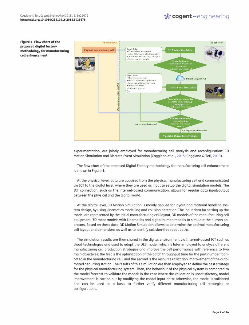
The flow chart of the proposed Digital Factory methodology for manufacturing cell enhancement is shown in Figure 1.
At the physical level, data are acquired from the physical manufacturing cell and communicated via ICT to the digital level, where they are used as input to setup the digital simulation models. The ICT connection, such as the internet-based communication, allows for regular data input/output between the physical and the digital world.
At the digital level, 3D Motion Simulation is mainly applied for layout and material handling sys-tem design, by using kinematics modelling and collision detection. The input data for setting up the model are represented by the initial manufacturing cell layout, 3D models of the manufacturing cell equipment, 3D robot models with kinematics and digital human models to simulate the human op-erators. Based on these data, 3D Motion Simulation allows to determine the optimal manufacturing cell layout and dimensions as well as to identify collision-free robot paths.
The simulation results are then shared in the digital environment via Internet-based ICT such as cloud technologies and used to adapt the DES model, which is later employed to analyze different manufacturing cell production strategies and improve the cell performance with reference to two main objectives: the first is the optimization of the batch throughput time for the part number fabri-cated in the manufacturing cell, and the second is the resource utilization improvement of the auto-mated deburring station. The results of this simulation are then employed to define the best strategy for the physical manufacturing system. Then, the behaviour of the physical system is compared to the model forecast to validate the model: in the case where the validation is unsatisfactory, model improvement is carried out by modifying the model input data; otherwise, the model is validated and can be used as a basis to further verify different manufacturing cell strategies or configurations.
Figure 1. Flow chart of the proposed digital factory methodology for manufacturing cell enhancement.
Page 5 of 14
Caggiano & Teti, Cogent Engineering (2018), 5: 1426676https://doi.org/10.1080/23311916.2018.1426676
The proposed Digital Factory methodology was applied to support the upgrade of the manufactur-ing cell under study with the introduction of a robotic deburring station.
3. Case study: Manufacturing cell automation improvementThe existing manufacturing cell to be automated is dedicated to the machining of an aircraft engine component, namely one turbine vane part number. Each turbine vane serial number goes through a production cycle consisting of two consecutive grinding operations, called Stage 1 and Stage 2, which are carried out on opposing sides of the vane. After each single-stage grinding process, the vane is transferred to a Coordinate Measuring Machine (CMM) to perform metrological inspection and then to a table where deburring operations are performed manually by a skilled operator.
Three main fundamental components make up the legacy manufacturing cell:
• A grinding machine tool equipped with a loading/unloading robot
• A coordinate measuring machine
• A manual deburring table
To date, the deburring process requires considerable human operator experience, manual ability and attention as it is performed manually with the help of small mills and grinding discs. A wrong procedure or an incorrect movement due to lack of concentration or tiredness may produce dam-ages to the vane which cannot be amended. Indeed, repair machining is not applicable when too much material has been removed via from the machined part and tolerances are very tight. Therefore, the result of such damages is the full rejection of the machined part, with very high rejec-tion costs related to both the expensive raw material and the manufacturing processes previously executed on the part.
Moreover, ergonomics analysis proves that manual material removal processes, such as deburring or polishing, can often cause physical impairments to the worker that could be avoided by introduc-ing a higher level of automation based on devices such as robots.
To reduce injury risks and upgrade the manufacturing cell, an automated deburring station equipped with an industrial robot has been designed to improve the overall automation of the man-ufacturing cell.
3.1. The automated manufacturing cellFollowing the integration of the robotic deburring station, the automated manufacturing cell is com-posed of three main constituent elements:
• A grinding machine tool provided with a loading/unloading robot
• A coordinate measuring machine
• An automated robotic deburring station
The automated deburring station employs a robot to perform the required tasks on the parts, includ-ing metrological assessment, actual deburring and transfer. To achieve these tasks, the station con-sists of a rotary table which is used for components input/output, a metrological inspection device equipped with a touch probe for metrological assessment aimed at verifying the position of given component data points and surfaces with respect to the robot (which allows an accurate positioning of the component geometry within the 3D coordinate reference system of the robot), a deburring machine tool with one mill and two abrasive discs to deburr different component features, and an automated robotic tool changer to replace the robot gripper when needed, e.g. when a different part number is processed.
Page 6 of 14
Caggiano & Teti, Cogent Engineering (2018), 5: 1426676https://doi.org/10.1080/23311916.2018.1426676
Out of the robotic deburring station, a human worker is responsible for manual tasks such as the assembly and disassembly of the parts and the complex fixtures required for accurate and stable part positioning within the grinding machine. These assembly operations are carried out on the in-put/output buffers of the grinding machine, without impacting on the machine processing time. Furthermore, manual part transfer among the grinding machine, the CMM and the automated de-burring station is performed by the worker.
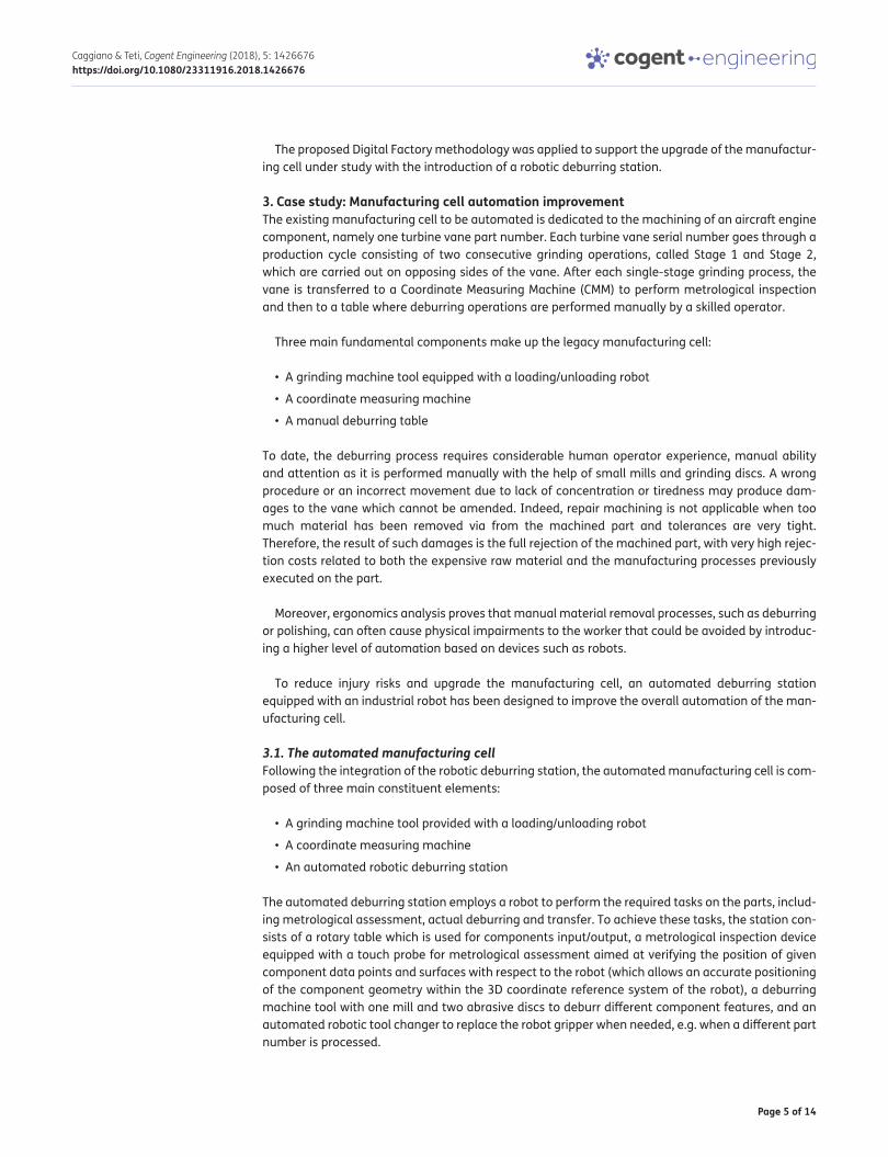
The components of the enhanced robotic manufacturing cell are reported in Table 1 and the gen-eral layout is shown in Figure 2.
4. Manufacturing cell upgrading through digital simulationFollowing the proposed Digital Factory approach presented in Section 2, two different digital simula-tion tools were jointly employed for the upgrade of the manufacturing cell under study: 3D Motion Simulation and Discrete Event Simulation.
4.1. Manufacturing cell layout and robot activity verification through 3D motion simulationThe first step of the decision-making procedure is the configuration of an appropriate layout for the enhanced manufacturing cell. The integration of the robotic deburring station necessitates the ac-curate examination of the manufacturing cell components layout in view of an efficient and safe robot motion. This type of analysis is accomplished via the employment of 3D Motion Simulation,
Table 1. Manufacturing cell componentsNo. Manufacturing cell components1. Input part storage
2. Component and fixture assembly place
3. Handling robot
4. Grinding machine
5. Rotary table
6. Deburring robot
7. Metrological inspection device
8. Deburring machine tool
9. Tool changer
10. CMM—Coordinate measuring machine
11. Output part storage
Figure 2. Robotic manufacturing cell layout.
Page 7 of 14
Caggiano & Teti, Cogent Engineering (2018), 5: 1426676https://doi.org/10.1080/23311916.2018.1426676
which represents an effective tool to simulate a manufacturing cell in a digital environment without performing physical experimentation on the manufacturing shop floor. This simulation is basically kinematic and employs 3D models of the machines and devices as well as 3D models of the indus-trial robots integrating kinematics modelling features.
The robot chosen for the deburring station is a 6 axis ABB IRB 2400-16 robot having a payload of 20 kg, a maximum reach of 1.55 m, a weight of 380 kg and a repeatability equal to 0.03–0.07 mm.
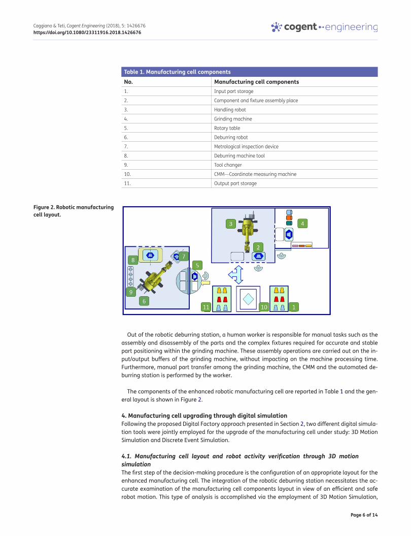
A 3D model of the robot with the matching kinematics was retrieved from a large robot data base. As regards the robot end effector, a robot gripper was newly designed so as to handle the compo-nents by inserting two prongs in the available part slots. In the 3D modelling and simulation soft-ware, the robot gripper was modelled as a device and its kinematics was formally described and included in the 3D model of the gripper. The kinematics modules of the 3D Motion Simulation soft-ware allowed to simulate the robot and gripper kinematics, and collision detection was employed to plan safe robot paths within the deburring station. Tasks were created to simulate all the steps of the deburring station production cycle, from the rotary motion of the table for introducing the new parts to robot part grabbing, metrological inspection for 3D part positioning control, and finally compo-nent deburring (Figure 3).
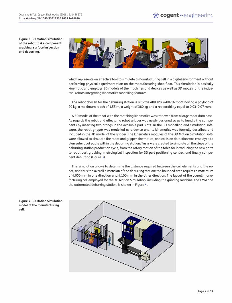
This simulation allows to determine the distance required between the cell elements and the ro-bot, and thus the overall dimension of the deburring station: the bounded area requires a maximum of 4,000 mm in one direction and 4,100 mm in the other direction. The layout of the overall manu-facturing cell employed for the 3D Motion Simulation, including the grinding machine, the CMM and the automated deburring station, is shown in Figure 4.
Figure 3. 3D motion simulation of the robot tasks: component grabbing, surface inspection and deburring.
Figure 4. 3D Motion Simulation model of the manufacturing cell.
Page 8 of 14
Caggiano & Teti, Cogent Engineering (2018), 5: 1426676https://doi.org/10.1080/23311916.2018.1426676
4.2. DES for manufacturing cell performance analysis and optimizationThe upgrade and reconfiguration of the new manufacturing cell involves the analysis of several as-pects related to system performance: as already mentioned in the introduction, any change carried out on a sub-system or component affects the behaviour of the overall system. Therefore, in order to achieve the desired outcome, the analysis and evaluation of the system performance and the examination of several alternative solutions should be carried out to support optimal decision-making.
Several mathematical models of different complexity have been developed for this (Gershwin, 1994; Matta et al., 2005). On the other hand, the employment of DES tools can considerably reduce the time and cost required for decision-making on cell reconfiguration. DES represents a valuable tool through which it is possible to study and analyze different what-if scenarios in a digital frame-work with limited computational effort. It can be employed to optimize the performance of a manu-facturing cell without experimenting on a physical system, which is particularly useful in case of a new system that is not already available as well as in the case of existing systems that are busy with actual production and cannot be stopped. Moreover, the efforts in terms of time and cost of physical experimentation, when it is feasible, are very high if compared to those of digital experimentation.
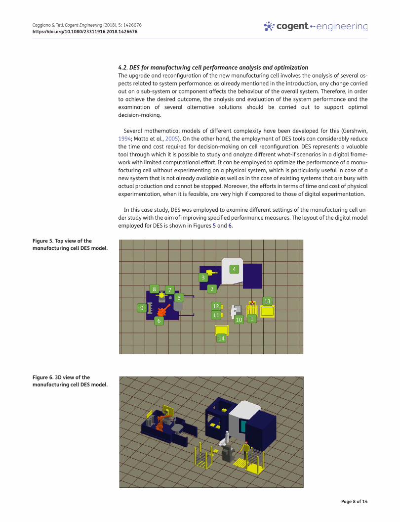
In this case study, DES was employed to examine different settings of the manufacturing cell un-der study with the aim of improving specified performance measures. The layout of the digital model employed for DES is shown in Figures 5 and 6.
Figure 5. Top view of the manufacturing cell DES model.
Figure 6. 3D view of the manufacturing cell DES model.
Page 9 of 14
Caggiano & Teti, Cogent Engineering (2018), 5: 1426676https://doi.org/10.1080/23311916.2018.1426676
4.2.1. DES for throughput time optimizationIn the proposed simulation framework, the first aim of DES is to evaluate different scenarios to im-prove the throughput time for a batch of the part number fabricated in the manufacturing cell. As the grinding operation process is the longest one carried out in the manufacturing cell, it has a strong impact on the overall throughput time: thus, two different hypotheses, both focused on the grinding machine processing sequence, are identified.
In the first simulation case (Case A), the grinding machine starts carrying out a Stage 1 operation on a new component. When Stage 1 is completed, another component is assembled on the Stage 1 fixture and then processed. After this, the grinding machine performs alternatively Stage 1 and Stage 2.
In this way, only one fixture per grinding stage is required in Case A: while the Stage 1 fixture-component assembly is inside the grinding machine, the next component ready for Stage 2 is as-sembled on the Stage 2 fixture at the assembly station located at the entrance of the grinding machine (element N. 2 in Figures 2 and 4).
In the second simulation case (Case B), the grinding machine performs all the Stage 1 operations for the whole batch, and only when all the components have undergone Stage 1, it starts carrying out Stage 2 on the entire batch. In Case B, in order to carry out assembly/disassembly of compo-nents and fixtures while the grinding machine is working, two fixtures for each grinding stage are required, for a total of 4 fixtures.
In both simulation cases, 3 shifts of 8 hours each, with breaks distributed during the day, are con-sidered for the human labor, and the maximum availability of the grinding machine is set to 85% to take into account stops and maintenance.
The results of the simulation runs for Case A and Case B show a very similar throughput time for an entire batch of components: 64.3 h against 64.1 h. As a consequence, Case A seems to be the optimal solution for several reasons; even if two fixtures per each grinding stage are available in Case B, there is no significant advantage in terms of throughput time. This is because no setup is required on the grinding machine to switch between Stage 1 and Stage 2, so that there is no signifi-cant benefit in processing subsequent components with the same stage operation rather than alter-nating Stage 1 and Stage 2. Moreover, the Work in Progress (WIP) of the manufacturing cell is much higher in Case B: the maximum number of components in the system is equal to the batch, and the first fully finished component is obtained only after completing all the Stage 1 operations on the whole batch. Therefore, Case B requires a higher investment in terms of fixtures cost, a larger buffer to collect the components waiting for Stage 2 operations and a longer time to have available a fully finished component.
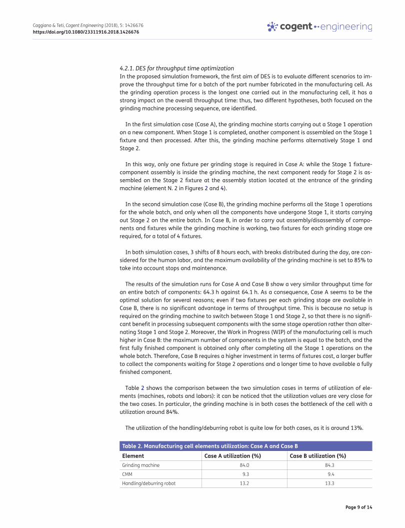
Table 2 shows the comparison between the two simulation cases in terms of utilization of ele-ments (machines, robots and labors): it can be noticed that the utilization values are very close for the two cases. In particular, the grinding machine is in both cases the bottleneck of the cell with a utilization around 84%.
The utilization of the handling/deburring robot is quite low for both cases, as it is around 13%.
Table 2. Manufacturing cell elements utilization: Case A and Case BElement Case A utilization (%) Case B utilization (%)Grinding machine 84.0 84.3
CMM 9.3 9.4
Handling/deburring robot 13.2 13.3
Page 10 of 14
Caggiano & Teti, Cogent Engineering (2018), 5: 1426676https://doi.org/10.1080/23311916.2018.1426676
4.2.2. DES for elements utilization improvementTo justify the investment required by the automated robotic deburring station, a higher utilization of the handling/deburring robot should be achieved.
To further exploit the capacity of the handling/deburring robot, additional part numbers, coming from other manufacturing cells in the same production department, could be introduced in the au-tomated deburring station for simulation. As long as the additional part numbers are geometrically comparable with the ones fabricated in the upgraded manufacturing cell, the robot is able to per-form deburring with only slight variations of the cycle time (as the latter is related to component dimensions).
To verify this hypothesis, starting from the cell configuration for Case A, new elements and logics are introduced in the DES model of the manufacturing cell. Novel logics for component routing are set up, in particular for the entrance of an external part number, as this should not interfere with the production cycle of the original part number.
As an example, the remaining time to the end of the grinding process is taken into consideration as a decisional parameter for component routing. The grinding machine is the bottleneck of the system and it should never be kept waiting because of the introduction of an additional part number, as this would increase the entire batch throughput time.
Two different hypotheses are simulated through DES, respectively called Case C and Case D. In Case C, the external part number components are introduced into the cell as a unique final batch requiring Stage 1 and Stage 2 deburring operations to be performed on the same component one immediately after the other. In Case D, the external part number components are introduced into the cell as two subsequent batches: first a Stage 1 batch and then a Stage 2 batch, to be deburred separately.
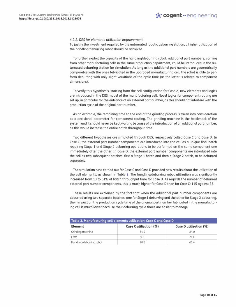
The simulation runs carried out for Case C and Case D provided new results about the utilization of the cell elements, as shown in Table 3. The handling/deburring robot utilization was significantly increased from 13 to 61% of batch throughput time for Case D. As regards the number of deburred external part number components, this is much higher for Case D than for Case C: 115 against 36.
These results are explained by the fact that when the additional part number components are deburred using two separate batches, one for Stage 1 deburring and the other for Stage 2 deburring, their impact on the production cycle time of the original part number fabricated in the manufactur-ing cell is much lower because their deburring cycle times are easier to manage.
Table 3. Manufacturing cell elements utilization: Case C and Case DElement Case C utilization (%) Case D utilization (%)Grinding machine 84.0 84.0
CMM 9.3 9.3
Handling/deburring robot 28.6 61.4
Page 11 of 14
Caggiano & Teti, Cogent Engineering (2018), 5: 1426676https://doi.org/10.1080/23311916.2018.1426676
5. Simulation model validationModel verification and validation represent a key issue in every simulation activity (Law, 2003). As simulation models are used to support decision-making, it is important to determine whether a model and its results are correct.
Different reasons can lead to a model’s failure: among these, inadequate model structure, incor-rect input values, observation errors, system noise, misinterpretation of simulation results, inappro-priate simulation software (Sargent, 2007).
Different levels of validation can be distinguished. Conceptual model validation assures that the assumptions underlying the conceptual model are correct and that the model representation of the problem is reasonable. Computerized model verification consists in assuring that the computer pro-gramming and implementation of the conceptual model is correct. Operational validation aims at determining that the model’s output behaviour has sufficient accuracy for the model’s intended purpose (Sargent, 2007). Data validity is defined as ensuring that the data employed for model build-ing, and experimentation are adequate and correct (Love & Back, 2000).
In this case study, the so-called predictive validation was performed on the DES simulation model (Sargent, 2007). Comparisons were made between the system’s behavior and the model’s forecast to determine if they are the same: the system data came from the physical manufacturing cell and consist of time and throughput data of the real manufacturing operations.
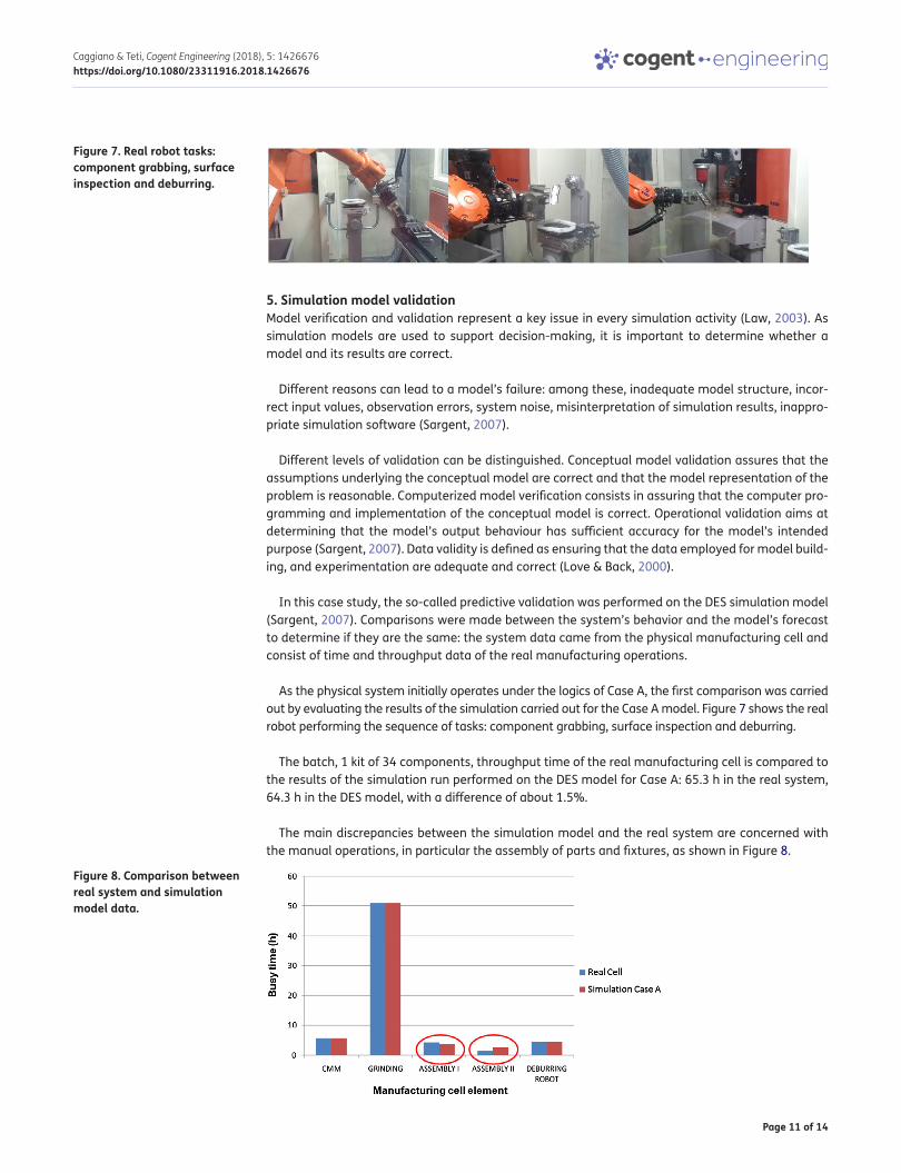
As the physical system initially operates under the logics of Case A, the first comparison was carried out by evaluating the results of the simulation carried out for the Case A model. Figure 7 shows the real robot performing the sequence of tasks: component grabbing, surface inspection and deburring.
The batch, 1 kit of 34 components, throughput time of the real manufacturing cell is compared to the results of the simulation run performed on the DES model for Case A: 65.3 h in the real system, 64.3 h in the DES model, with a difference of about 1.5%.
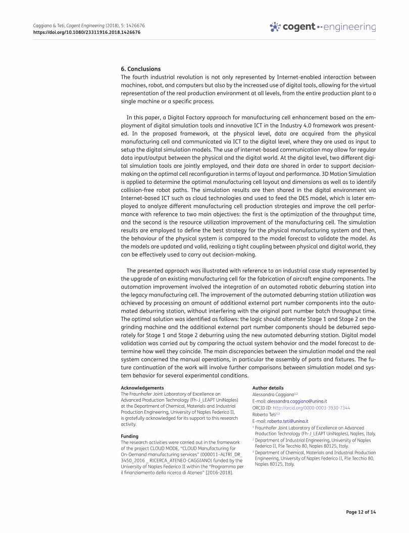
The main discrepancies between the simulation model and the real system are concerned with the manual operations, in particular the assembly of parts and fixtures, as shown in Figure 8.
Figure 7. Real robot tasks: component grabbing, surface inspection and deburring.
Figure 8. Comparison between real system and simulation model data.
Page 12 of 14
Caggiano & Teti, Cogent Engineering (2018), 5: 1426676https://doi.org/10.1080/23311916.2018.1426676
6. ConclusionsThe fourth industrial revolution is not only represented by Internet-enabled interaction between machines, robot, and computers but also by the increased use of digital tools, allowing for the virtual representation of the real production environment at all levels, from the entire production plant to a single machine or a specific process.
In this paper, a Digital Factory approach for manufacturing cell enhancement based on the em-ployment of digital simulation tools and innovative ICT in the Industry 4.0 framework was present-ed. In the proposed framework, at the physical level, data are acquired from the physical manufacturing cell and communicated via ICT to the digital level, where they are used as input to setup the digital simulation models. The use of internet-based communication may allow for regular data input/output between the physical and the digital world. At the digital level, two different digi-tal simulation tools are jointly employed, and their data are shared in order to support decision-making on the optimal cell reconfiguration in terms of layout and performance. 3D Motion Simulation is applied to determine the optimal manufacturing cell layout and dimensions as well as to identify collision-free robot paths. The simulation results are then shared in the digital environment via Internet-based ICT such as cloud technologies and used to feed the DES model, which is later em-ployed to analyze different manufacturing cell production strategies and improve the cell perfor-mance with reference to two main objectives: the first is the optimization of the throughput time, and the second is the resource utilization improvement of the manufacturing cell. The simulation results are employed to define the best strategy for the physical manufacturing system and then, the behaviour of the physical system is compared to the model forecast to validate the model. As the models are updated and valid, realizing a tight coupling between physical and digital world, they can be effectively used to carry out decision-making.
The presented approach was illustrated with reference to an industrial case study represented by the upgrade of an existing manufacturing cell for the fabrication of aircraft engine components. The automation improvement involved the integration of an automated robotic deburring station into the legacy manufacturing cell. The improvement of the automated deburring station utilization was achieved by processing an amount of additional external part number components into the auto-mated deburring station, without interfering with the original part number batch throughput time. The optimal solution was identified as follows: the logic should alternate Stage 1 and Stage 2 on the grinding machine and the additional external part number components should be deburred sepa-rately for Stage 1 and Stage 2 deburring using the new automated deburring station. Digital model validation was carried out by comparing the actual system behavior and the model forecast to de-termine how well they coincide. The main discrepancies between the simulation model and the real system concerned the manual operations, in particular the assembly of parts and fixtures. The fu-ture continuation of the work will involve further comparisons between simulation model and sys-tem behavior for several experimental conditions.
AcknowledgementsThe Fraunhofer Joint Laboratory of Excellence on Advanced Production Technology (Fh-J_LEAPT UniNaples) at the Department of Chemical, Materials and Industrial Production Engineering, University of Naples Federico II, is gratefully acknowledged for its support to this research activity.
FundingThe research activities were carried out in the framework of the project CLOUD MODE, “CLOUD Manufacturing for On-Demand manufacturing services” (000011–ALTRI_DR_ 3450_2016 _ RICERCA_ATENEO-CAGGIANO) funded by the University of Naples Federico II within the “Programma per il finanziamento della ricerca di Ateneo” [2016-2018].
Author detailsAlessandra Caggiano1,2
E-mail: [email protected] ID: http://orcid.org/0000-0003-3930-7344Roberto Teti1,3
E-mail: [email protected] Fraunhofer Joint Laboratory of Excellence on Advanced
Production Technology (Fh-J_LEAPT UniNaples), Naples, Italy.2 Department of Industrial Engineering, University of Naples
Federico II, P.le Tecchio 80, Naples 80125, Italy.3 Department of Chemical, Materials and Industrial Production
Engineering, University of Naples Federico II, P.le Tecchio 80, Naples 80125, Italy.
Page 13 of 14
Caggiano & Teti, Cogent Engineering (2018), 5: 1426676https://doi.org/10.1080/23311916.2018.1426676
Citation informationCite this article as: Digital factory technologies for robotic automation and enhanced manufacturing cell design, Alessandra Caggiano & Roberto Teti, Cogent Engineering (2018), 5: 1426676.
ReferencesBracht, U., & Masurat, T. (2005). The Digital Factory between
vision and reality. Computers in Industry, 56(4), 325–333. https://doi.org/10.1016/j.compind.2005.01.008
Caggiano, A., Caiazzo, F., & Teti, R. (2015). Digital factory approach for flexible and efficient manufacturing systems in the aerospace industry. Procedia CIRP, 37, 122–127. https://doi.org/10.1016/j.procir.2015.08.015
Caggiano, A., & Teti, R. (2012, June 12–13). Digital manufacturing cell design for performance increase. In 1st CIRP Global Web Conference on Interdisciplinary Research in Production Engineering, CIRPE, Procedia CIRP (Vol. 2, pp. 64–69). ISSN 2212-8271.
Caggiano, A., & Teti, R. (2013). Modelling, analysis and improvement of mass and small batch production through advanced simulation tools. Procedia CIRP, 12, 426–431. https://doi.org/10.1016/j.procir.2013.09.073
ElMaraghy, H. A. (2006). Flexible and reconfigurable manufacturing systems paradigms. International Journal of Flexible Manufacturing Systems (IJFMS), 17(4), 261–276.
Gershwin, S. B. (1994). Manufacturing systems engineering. Englewood Cliffs, NJ: PTR Prentice Hall.
Gregor, M., Medvecký, Š., Matuszek, J., & Štefánik, A. (2009). Digital factory. 3. No. 3. Journal of Automation, Mobile Robotics & Intelligent Systems (JAMRIS), 3(3), 123–132. ISSN 1897-8649.
Horizon. (2020). Retrieved from http://ec.europa.eu/programmes/horizon2020/en/h2020-section/industrial-leadership
Hosseinpour, F., & Hajihosseini, H. (2009, March). Importance of simulation in manufacturing. 51. World Academy of Science, Engineering and Technology, 51, 285–288. ISSN 2070–3724.
Kádár, B., Lengyel, A., Monostori, L., Suginishi, Y., Pfeiffer, A., & Nonaka, Y. (2010). Enhanced control of complex production structures by tight coupling of the digital and the physical worlds. CIRP Annals, 59, 437–440. https://doi.org/10.1016/j.cirp.2010.03.123
Kühn, W. (2006). Digital factory - Integration of simulation enhancing the product and production process towards operative control and optimisation. International Journal of Simulation, 7(7), 27–39. ISSN 1473–8031
Law, A. M. (2003, December 7–10). Model verification and validation. In S. Chick, P. J. Sanchez, D. Ferrin, & D. J. Morrice (Eds.), Proceedings of the 2003 winter simulation conference (pp. 66–70). New Orleans, LA.
Love, G., & Back, G. (2000, August 6–10). Model verification and validation for rapidly developed simulation models: Balancing cost and theory. In Proceedings of the 18th international conference of the system dynamics society. Bergen, Norway.
Maropoulos, P. G. (2003). Digital enterprise technology - defining perspectives and research priorities. International Journal of Computer Integrated Manufacturing, 16(7–8), 467–478. https://doi.org/10.1080/0951192031000115787
Matta, A., Semeraro, Q., & Tolio, T. (2005). Configuration of AMSs. In A. Matta & Q. Semeraro (Eds.), Design of advanced manufacturing systems (pp. 125–189). Springer. ISBN 1-4020-2930-6. https://doi.org/10.1007/1-4020-2931-4
Monostori, L. (2014). Cyber-physical production systems: Roots, expectations and R&D challenges. In Proceedings of the 47th CIRP Conference on Manufacturing Systems, Procedia CIRP 17 (pp. 9–13).
Monostori, L., Kádár, B., Bauernhansl, T., Kondoh, S., Kumara, S., Reinhart, G., … Ueda, K. (2016). Cyber-physical systems in manufacturing. CIRP Annals, 65(2), 621–641. https://doi.org/10.1016/j.cirp.2016.06.005
Mourtzis, D., Papakostas, N., Mavrikios, D., Makris, S., & Alexopoulos, K. (2011, September 28-30). The role of simulation in digital manufacturing – Applications and outlook, keynote paper. In 7th international conference on digital enterprise technology (DET 2011) (pp. 189–203). Athens, Greece.
Papakostas, N., Mavrikios, D., Makris, S., & Alexopoukos, K. (2015). The role of simulation in digital manufacturing: Applications and outlook. International Journal of Computer Integrated Manufacturing, 28, 3-24.
Sargent, R. G. (2007, December 9–12). Verification and validation of simulation models. In Proceedings of the 2007 winter simulation conference (pp.124–137). Washington, DC.
Shariatzadeh, N., Lundholm, T., Lindberg, L., & Sivard, G. (2016). Integration of digital factory with smart factory based on internet of things. Procedia CIRP, 50, 512–517. https://doi.org/10.1016/j.procir.2016.05.050
Smith, J. S. (2003). Survey on the use of simulation for manufacturing system design and operation. Journal of Manufacturing Systems, 22(2), 157–171. https://doi.org/10.1016/S0278-6125(03)90013-6
Smith, J., Kreutzer, S., Moeller, C., & Carlberg, M. (2016). Industry 4.0. Study for the ITRE committee (pp. 1–81).
Westkämper, E. (2007b). Digital manufacturing in the global era. In P. F. Cunha & P. G. Maropoulos (Eds.), Digital enterprise technology: Perspectives and future challenges (pp. 3–14). New York, NY: Springer. ISBN 978-0-387-49863-8. https://doi.org/10.1007/978-0-387-49864-5
Westkämper, E. (2007a). Strategic development of factories under the influence of emergent technologies. CIRP Annals, 56(1), 419–422. https://doi.org/10.1016/j.cirp.2007.05.100
Westkämper, E., Constantinescu, C., & Hummel, V. (2006). New paradigms in manufacturing engineering: Factory life cycle. Annals of the Academic Society for Production Engineering, Research and Development, XIII(1), 143–147.
.
Page 14 of 14
Caggiano & Teti, Cogent Engineering (2018), 5: 1426676https://doi.org/10.1080/23311916.2018.1426676
© 2018 The Author(s). This open access article is distributed under a Creative Commons Attribution (CC-BY) 4.0 license.You are free to: Share — copy and redistribute the material in any medium or format Adapt — remix, transform, and build upon the material for any purpose, even commercially.The licensor cannot revoke these freedoms as long as you follow the license terms.
Under the following terms:Attribution — You must give appropriate credit, provide a link to the license, and indicate if changes were made. You may do so in any reasonable manner, but not in any way that suggests the licensor endorses you or your use. No additional restrictions You may not apply legal terms or technological measures that legally restrict others from doing anything the license permits.
Cogent Engineering (ISSN: 2331-1916) is published by Cogent OA, part of Taylor & Francis Group. Publishing with Cogent OA ensures:• Immediate, universal access to your article on publication• High visibility and discoverability via the Cogent OA website as well as Taylor & Francis Online• Download and citation statistics for your article• Rapid online publication• Input from, and dialog with, expert editors and editorial boards• Retention of full copyright of your article• Guaranteed legacy preservation of your article• Discounts and waivers for authors in developing regionsSubmit your manuscript to a Cogent OA journal at www.CogentOA.com