digital halftoning. summary of 30.1.06 lecture how to produce illusion of the original tonal quality...
TRANSCRIPT

Digital Halftoning

Summary of 30.1.06 lecture
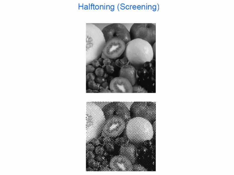
• How to produce illusion of the original tonal quality of a image by judicious placements of dots.
• How to generate an image with fewer amplitude levels but perceptually similar to the original.
• High frequency patterns are perceived as their macroscopic averages.
• Halftoning techniques
– Dithering
» Disperse dot
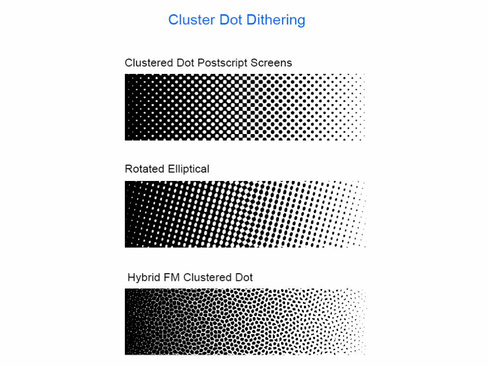
» Cluster dot
– Error Diffusion
» Floyd Steinberg
Dithering mask Ξ screen
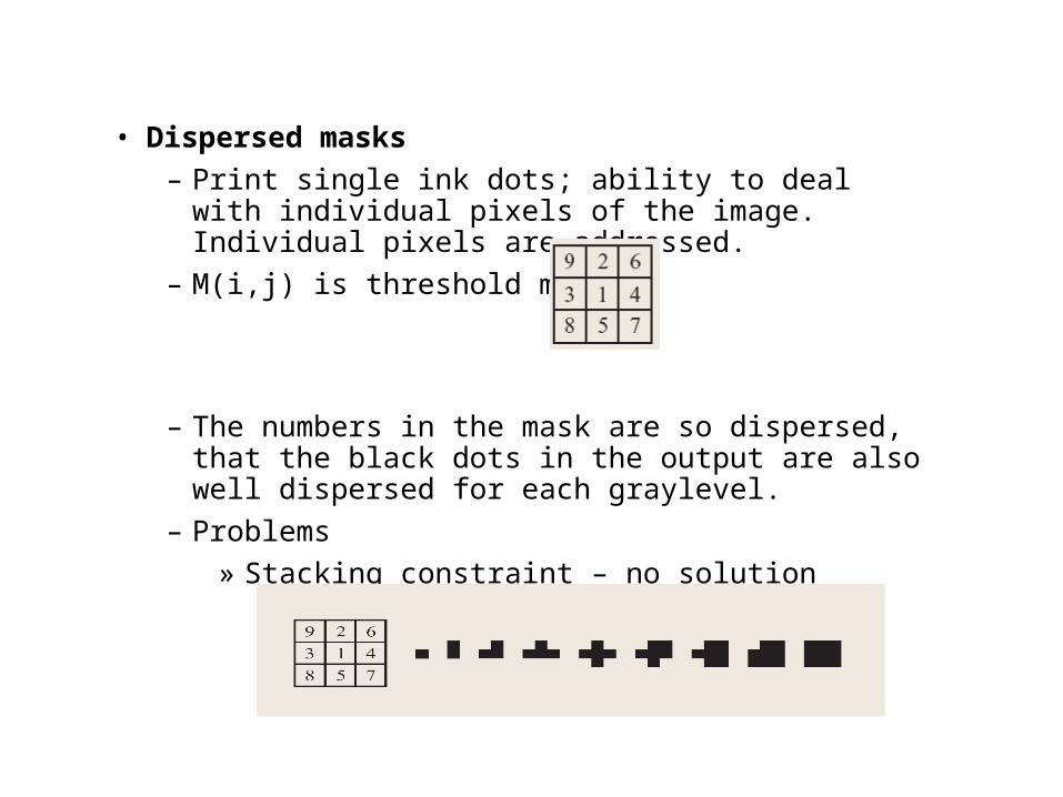
• Dispersed masks
– Print single ink dots; ability to deal with individual pixels of the image. Individual pixels are addressed.
– M(i,j) is threshold mask
– The numbers in the mask are so dispersed, that the black dots in the output are also well dispersed for each graylevel.
– Problems
» Stacking constraint – no solution

» Periods of n& m can sometimes be detected
• Solution: make nxm >> no. of distinct threshold elements, useful in blue noisemasks (low frequency attenuated)
» Large nxm ; poor spatial resolution
bigger mask: more gray levels.
i.e Better gray/ dynamic range /colour resolution
» Large masks are obtained using 2 smaller masks based on Thue-Morse sequence.
• Clustered masks
– They average over a neighborhood & replace by cluster of dots. Pixels in clustered dot are nucleated in groups in regular intervals.
– Tradeoff between no.of gray levels to be rendered and size of cluster
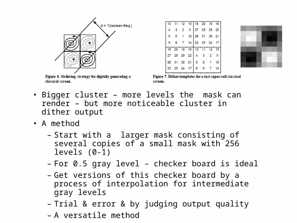
• Bigger cluster – more levels the mask can render – but more noticeable cluster in dither output
• A method
– Start with a larger mask consisting of several copies of a small mask with 256 levels (0-1)
– For 0.5 gray level – checker board is ideal
– Get versions of this checker board by a process of interpolation for intermediate gray levels
– Trial & error & by judging output quality
– A versatile method
Calibration of dither masks :
In constructing dither masks, we assume that the no.of black pixels in a hlaftone pattern proportional to gray levels
We call such - linear dither masks
Will not work if there is dot overlap or dot gain
Another point: Non linearity effect when a quantity called lightness is used to measure graylevels
Lightness – perceived as log of luminance (how bright we see luminance)
To compensate for this , apply a tone reproduction curve (TRC) to the input data & then use a linear dither mask.


Colour:
• Use 4 different masks (screens) one for each color + black. using the same mask 4 times is usually avoided by the screens set at different angles.
• Registration problem (moire pattren)

• Error Diffusion:
– Running error
» Where at pixel location K, r(k) is a gray value number between 0 (w) – 1 (B)
» ρ( k) = 0 for white
= 1 for black
» The running error satisfies the recursion

• Simple error diffusion:
– is defined by taking ρ(n+1) to satisfy the greedy algorithm.
– i.e. ρ(n+1) takes the value 0 or 1 which ever minimizes Є (n+1), with a tie breaking rule (when error is exactly 0.5).
• It can be shown that Є (n) lies in the interval [-1/2, 1/2] for any choice of the sequence
Thus Є(n) is bounded and

2 PAPERS

Minimum MSE output: result of a fixedthreshold.
The result of dithering with a white noisethreshold.

CLUSTERED-DOT
Result of halftoning with a 4x4 super-cell classical screen.


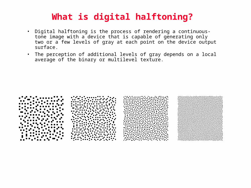
What is digital halftoning?
• Digital halftoning is the process of rendering a continuous-tone image with a device that is capable of generating only two or a few levels of gray at each point on the device output surface.
• The perception of additional levels of gray depends on a local average of the binary or multilevel texture.

The Two Fundamental Goalsof Digital Halftoning
• Representation of Tone
– smooth, homogeneous texture.
– free from visible structure or contouring.
Diamond dot screen
Bayer screen
Error diffusion

Modulation Strategies
• Amplitude modulation - dot size varies, dot spacing is fixed.
• Frequency modulation - dot spacing varies, dot size is fixed.

Signal Spectra
f
f
f

Discrete Fourier Transform
• A tool for measuring the frequency spectrum of signals.
• For discrete time signals xn n=0,1, …, N-1.The Discrete Fourier transform (DFT) can be calculated by
The inverse Fourier transform calculates the time sequence from the frequency components:
• Both the time sequence and the frequency components are complex numbers in general. The power spectral density of the time sequence x is
1,...,1,0 2 NmXm
Xm xnn0
N 1
exp( j2mn / N)
xn 1N
Xmn0
N 1
exp( j2mn / N)

Application to Images
• We need to define the concept of spatial frequency. This is the number of cycles measured per unit distance.
low frequency
high frequency

Basis Set
• Sinusoid is the basis for measuring spectral characteristics in the Fourier transform. Note that
• The Fourier transform represents each signal sample as weighted average of sinusoids
)2sin()2cos()2exp( ftjftftj
DC term
Fundamental frequency
Second harmonic
xn 1N
Xmn0
N 1
exp( j2mn / N)
X0
NX1
Nexp( j2n 1
N) X2
Nexp( j2n 2
N) ...
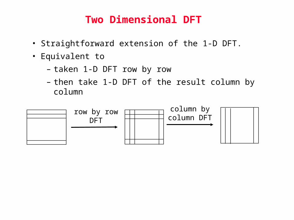
Two Dimensional DFT
• Straightforward extension of the 1-D DFT.
• Equivalent to
– taken 1-D DFT row by row
– then take 1-D DFT of the result column by column
row by rowDFT
column bycolumn DFT

Human Visual Response
• The human perception system do not have equal response
to all spatial frequencies.
• As the spatial frequencies become higher and higher, our
ability to perceive the pattern will be lower and lower.
• It turns out that our ability to perceive very low frequency
patterns also decreases as the frequency decreases.
• These characteristics can be captured using a contrast
sensitivity function.

Contrast Sensitivity Function
• [Mannos and Sakrison, 1974]
Spatial frequency (cycles per degree perceived by the eyes)
fr

Screening or Dithering
Outline
1. Screening as a threshold process
2. Macroscreens
3. Spectral characteristics of screens

Screening is a Thresholding Process
• Simple point-to-point transformation of each pixel in the continuous-tone image to a binary value.
• Process requires no memory or neighborhood information.
1 1 1 1
1 3 3 1
1 3 3
1 1 1
1
1
0.5
1.52.5
3.5
1 1 1 1
1 3 3 1
1 3 3
1 1 1
1
1
Continuous-Tone Image
Halftone Image
Compare
0.5
1.52.5
3.5
Threshold Matrix
Threshold
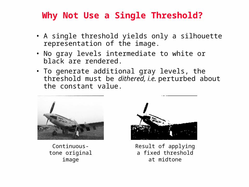
Why Not Use a Single Threshold?
• A single threshold yields only a silhouette representation of the image.
• No gray levels intermediate to white or black are rendered.
• To generate additional gray levels, the threshold must be dithered, i.e. perturbed about the constant value.
Continuous-tone original image
Result of applying a fixed threshold at midtone

Basic Structure of Screening Algorithm
1 1 1 1
1 3 3 1
1 3 3
1 1 1
1
1
0.5
1.52.5
3.5
1 1 1 1
1 3 3 1
1 3 3
1 1 1
1
1
Continuous-Tone Image
Halftone Image
Compare
0.5
1.52.5
3.5
Threshold Matrix
The threshold matrix is periodically tiled over the entire continuous-tone image.
Terminology
• The screening process is also called dithering.
• However, the term dithering is sometimes applied to any digital halftoning process, not just that consisting of a pixel-to-pixel comparision with thresholds in a matrix.
• The following are equivalent terms for the threshold matrix:
– screen
– dither matrix
– mask

How Tone is Rendered
• If we threshold the screen against a constant gray value, we obtain the binary texture used to represent that constant level of absorptance.
12
3 4
56
7 8
9
10
1112
13
14
15 16
7 7 7 77 7 7 77 7 7 77 7 7 7
7 7 7 77 7 7 77 7 7 77 7 7 7
7 7 7 77 7 7 77 7 7 77 7 7 7
7 7 7 77 7 7 77 7 7 77 7 7 7
7 7 7 77 7 7 77 7 7 77 7 7 7
7 7 7 77 7 7 77 7 7 77 7 7 7
7 7 7 77 7 7 77 7 7 77 7 7 7
7 7 7 77 7 7 77 7 7 77 7 7 7
7 7 7 77 7 7 77 7 7 77 7 7 7
Threshold Matrix
Halftone ImageContinuous-Tone Image
Compare
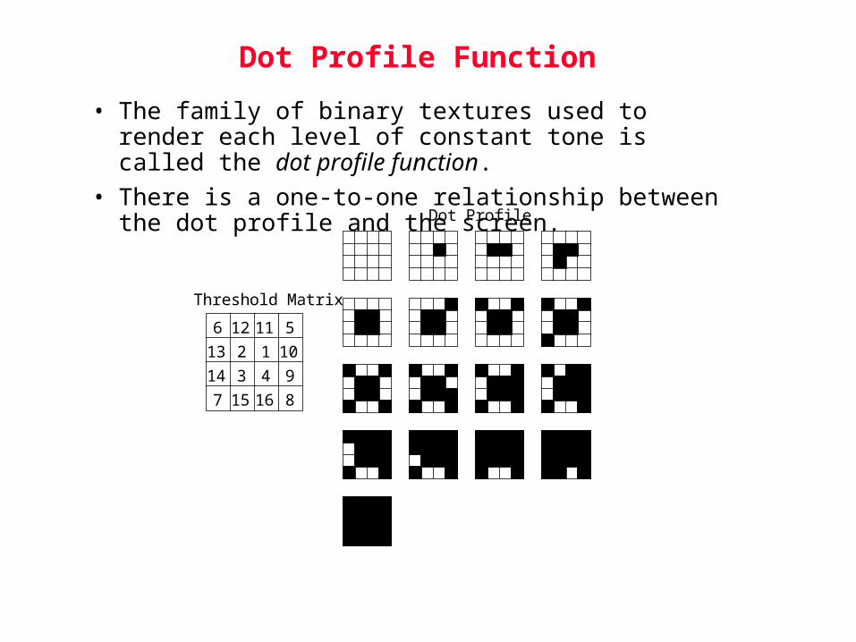
Dot Profile Function
• The family of binary textures used to render each level of constant tone is called the dot profile function.
• There is a one-to-one relationship between the dot profile and the screen.
12
3 4
56
7 8
9
10
1112
13
14
15 16
Threshold Matrix
Dot Profile
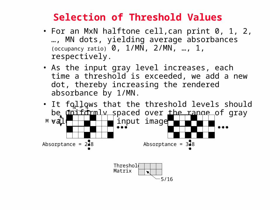
Selection of Threshold Values• For an MxN halftone cell,can print 0, 1, 2, …, MN dots,
yielding average absorbances (occupancy ratio) 0, 1/MN, 2/MN, …, 1, respectively.
• As the input gray level increases, each time a threshold is exceeded, we add a new dot, thereby increasing the rendered absorbance by 1/MN.
• It follows that the threshold levels should be uniformly spaced over the range of gray values of the input image.
M = 2
N = 4
Threshold Matrix
Absorptance = 2/8 Absorptance = 3/8
5/16
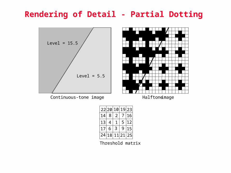
Rendering of Detail - Partial Dotting
7
1
2
34 5
6
8
9
10
11
1213
14
15
16
Threshold matrix
17
18
1920
21
22 23
24 25
Continuous-tone image Halftone image
Level = 15.5
Level = 5.5
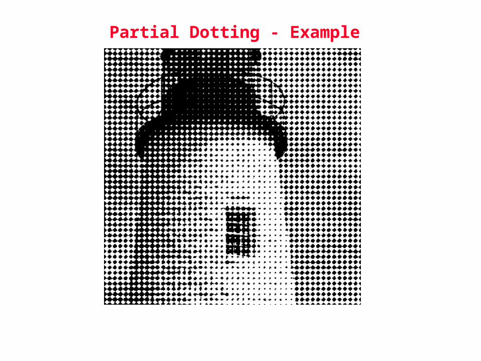
Partial Dotting - Example

Spatial Arrangement of Thresholds
• For clustered dot textures, thresholds that are close in value are located close together in the threshold matrix
1
23
4
5 6
7
8910
11
12
13 14
1516
Threshold matrix
Halftone texture for gray level 5/16

Spatial Arrangement of Thresholds (cont.)
• For dispersed dot textures, thresholds that are close in value are located far apart in the threshold matrix.
1
2 3
4
5
6
7
8
9
10
1112
13
14
1516
Threshold matrix
Halftone texture for gray level 5/16

Detail Rendition with Dispersed Dot Screens
• Compute the halftone image in the example given below to show how detail is rendered with a dispersed dot screen.
Threshold Matrix
Halftone ImageContinuous-Tone Image absorptance = 3/16 and 13/16
Compare
3 3 3 33 3 3 33 3 3 33 3 3 33 3 3 33 3 3 33 3 3 33 3 3 3
13 13 13 1313 13 13 1313 13 13 1313 13 13 1313 13 13 1313 13 13 1313 13 13 1313 13 13 1313 13 13 13
13 13 13 1313 13 13 1313 13 13 13
3 3 3 33 3 3 33 3 3 3
3 3 3 3
3 33
13 1313 1313 13
131313
13
13 13 1313 133 13
13133333 1313
3 3 3 33 3 3 13
3 3 3 33 3 33 3
1313
13
1
2 3
4
5
6
7
8
9
10
1112
13
14
1516

Detail Rendition with Dispersed Dot Screens
• Solution
Threshold Matrix
Halftone ImageContinuous-Tone Image
absorptance = 3/16 and 13/16
Compare
3 3 3 33 3 3 33 3 3 33 3 3 33 3 3 33 3 3 33 3 3 33 3 3 3
13 13 13 1313 13 13 1313 13 13 1313 13 13 1313 13 13 1313 13 13 1313 13 13 1313 13 13 1313 13 13 13
13 13 13 1313 13 13 1313 13 13 13
3 3 3 33 3 3 33 3 3 3
3 3 3 3
3 33
13 1313 1313 13
131313
13
13 13 1313 133 13
13133333 1313
3 3 3 33 3 3 13
3 3 3 33 3 33 3
1313
13
1
2 3
4
5
6
7
8
9
10
1112
13
14
1516
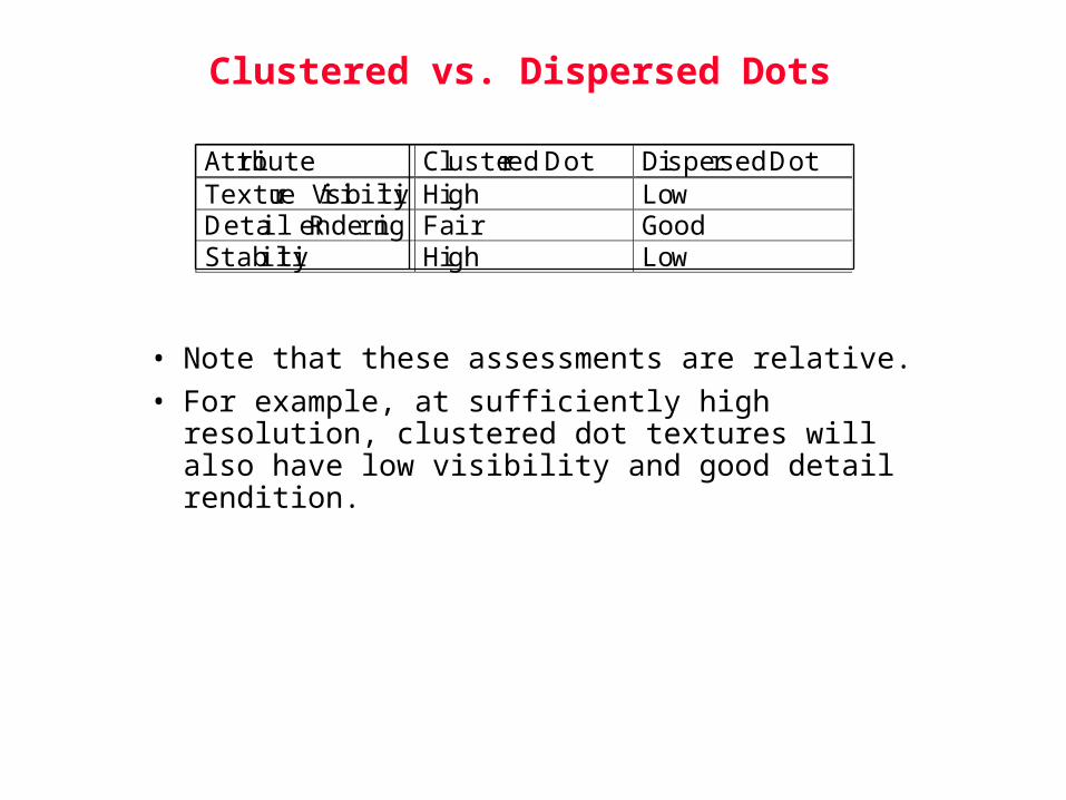
Clustered vs. Dispersed Dots
• Note that these assessments are relative.
• For example, at sufficiently high resolution, clustered dot textures will also have low visibility and good detail rendition.
Attribute Clustered Dot Dispersed DotTexture Visibility High LowDetail Rendering Fair GoodStability High Low


Error Diffusion (Floyd Steinberg)


Floyd-Steinberg Error Diffusion
• [Floyd and Steinberg 1975]
• The filter coefficients for Floyd-Steinberg error diffusion are
• There are two different but equivalent implementations.
Q(.)xm,n bm,n
++
++
hk,l
--
um,n
em,n
3/16 5/16
7/16
1/16
*
current pixel location
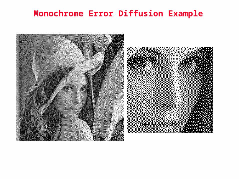
Monochrome Error Diffusion Example

Other Error Diffusion FiltersJarvis, Judice and Ninke
Stucki
3/48 5/48
7/48*
current pixel
location
3/48
3/48
3/481/48 1/485/48
5/48
5/48
7/48
2/42 4/42
8/42*
current pixel
location
2/42
2/42
2/421/42 1/424/42
4/42
4/42
8/42

Implementation 2 (Filtering Approach)
• At each pixel location, compute um,n.
• Threshold um,n to give the output bm,n.
• Calculate and store the quantizer error em,n.
Q(.)xm,n bm,n
++
++
hk,l
--
um,n
em,n
(3/16)* em-1,n+1(5/16)* em-1,n
(7/16)* em,n-1
(1/16)* em-1,n-1
*
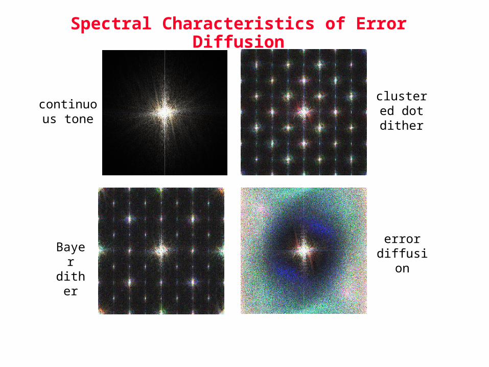
Spectral Characteristics of Error Diffusion
error diffusion
continuous tone
Bayer dither
clustered dot dither

Spectral Characteristics of Error Diffusion
• Noise energy mostly in the high frequency region.
• No obvious spikes in the error diffusion spectrum.Hence, there is no obvious periodicity.
• Some “cut-off” frequency below which there is very little noise energy.
– Ulichney showed empirically that this is roughly the principal frequency.
– Usually called the blue noise characteristics.
• The noise spectrum is skewed, that is, not circularly symmetric with respect to the two dimensional frequency plane.Empirical results show that this is due to the asymmetry in the error diffusion filter.

Improvements to Error Diffusion
• Error diffusion suffer from some patterning and worm artifacts. There have been a great deal of work to improve the quality of error diffusion. Here are some general areas that people have worked on:
– alternative scanning strategies
– randomize the quantizer threshold
– randomize the filter coefficients
– optimize the error diffusion filter
– adaptive error diffusion
– design multiple error diffusion filters and switch among them depending on image characteristics

Color
• Printers render color by placing dots of 3 or more subtractive colorants on the paper.
– 3 color printer: cyan, magenta, yellow (CMY)
– 4 color printer: CMY plus black (K)
– >4 color printer: additional primaries are used to yield a larger gamut, and reduce visibility of halftone texture
• Color images to be printed come from additive color systems
– Image capture devices (camera or scanner): red, green, blue (RGB)
– Display devices (CRT or LCD): RGB
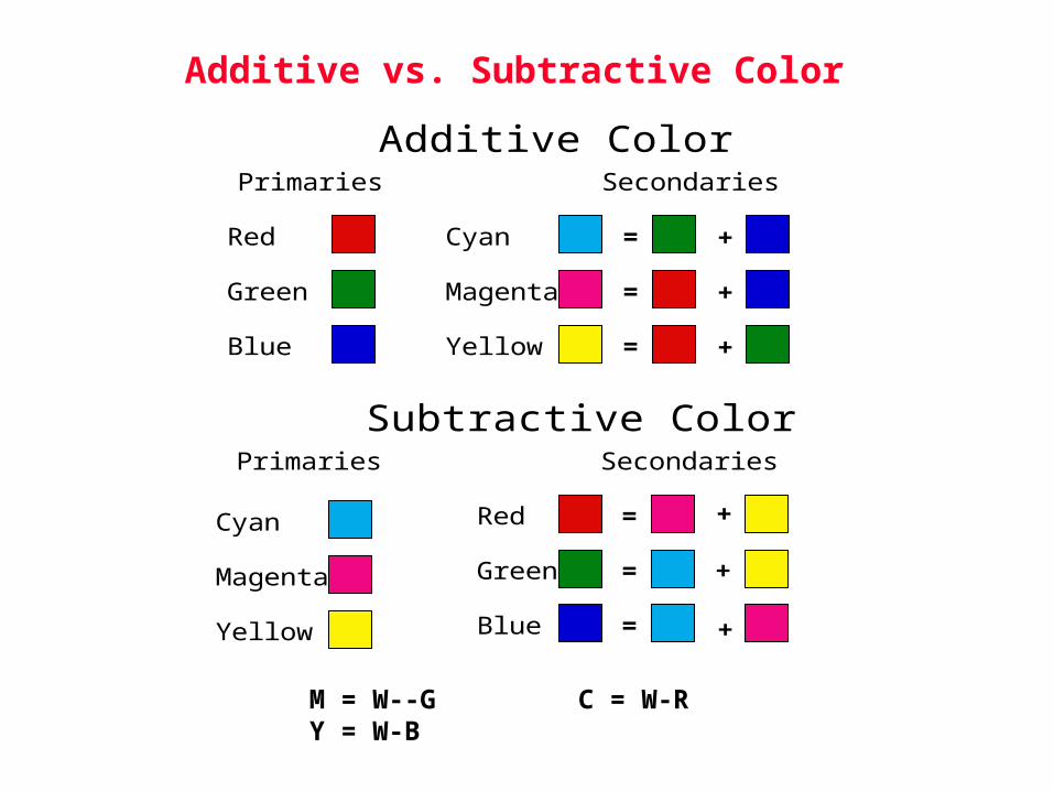
Additive vs. Subtractive Color
Subtractive ColorPrimaries Secondaries
Red
Green
Blue
Cyan
Magenta
Yellow
=
=
=
Additive ColorPrimaries
Red
Green
Blue
Secondaries
Cyan
Magenta
Yellow
= +
=
=
+
+
+
+
+
M = W--G C = W-R Y = W-B

Two Fundamental Problems of Color Printing
• Conversion from RGB to CMYK.
• Determination of what dots to print and where for a given CMYK amount.
• The color as expressed in a device-independent color space, such as CIE L*a*b*, that results for a given CMYK amount depends on both
– print mechanism and colorants,
– halftoning algorithm.
• Ideally, the halftoning algorithm and RGB to CMYK conversion should be designed together.
• In practice, halftoning algorithm is developed first to render a given amount of CMYK.
• Then, RGB to CMYK conversion is developed by treating printer and halftoning algorithm together as a black box.

CMYK Halftoning: Periodic, Clustered Dot Screens
• These algorithms emulate well-established techniques developed for conventional offset and lithographic printing.
• The screens are rotated relative to each other to minimize formation of rosettes:
– darkest two colors (M and K) are separated by 45 degrees,
– next lighter color (C) is separated from these two by 22 degrees,
– lightest color (Y) is not rotated.
• The finite addressability of the printer necessitates careful design of the screens which is usually done by hand.
• CMYK halftones can each be generated independently.
• Typically used in laser EP printers.
CMYK Halftoning: Dispersed Dot, Aperiodic Algorithms
• Since the halftone textures have no periodic structure, rosettes cannot occur.
• However, interference between colorant planes is still possible, and results in graininess or mottle.
• Can use either:
– blue noise mask,
– error diffusion.
• Halftone patterns can either be dot-on-dot or dot-off-dot.
• Typically used in IJ printers.

Dot-on-Dot Halftoning
• Eliminates possibility of interference between colorant planes.
• Requires better control of dot placement between colorant planes.
• Restricts gamut.
• Results in more visible dots in highlights.
• CMYK halftones can be generated independently.

Dot-off-Dot Halftoning
• Registration of colorant planes not critical.
• Less visible dots in highlight areas.
• Enforcement of dot-off-dot behavior must be an explicit part of the halftoning algorithm.
• CMYK halftones must be generated jointly.

Conversion to Printer CMYK
• Convert input RGB image to a device-independent color space, such as CIE L*a*b*.
• Characterize color printer/halftoning algorithm combination.
• Develop mapping from CIE L*a*b* to printer CMYK:
– interpolation for 3-D transformation between L*a*b* and CMYK,
– account for gamut limitations,
– undercolor removal, e.g. replace some part of equal amounts of CMY by an equivalent amount of K.

Color halftoning


RECURSIVE TESSELLATION

Dithering with a 4th order recursive tessellation array.
Values of a 4th-order recursive tessellation template.

BLUE NOISE
Spectra Characteristics of a bluenoisedither pattern. (a) Energy peak at principal frequency, (b) Sharp low frequency cut-off, and (c) high frequency white noise.