digital handset operation - amazon web...
TRANSCRIPT
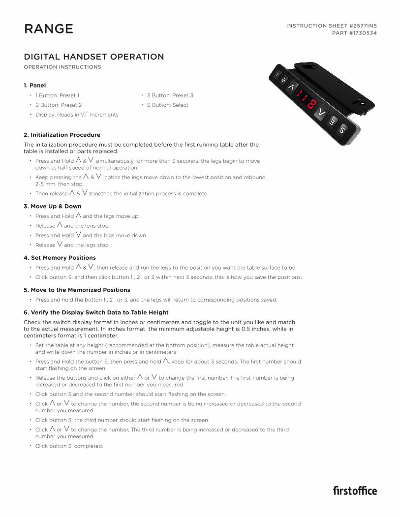
1. Panel
2. Initialization ProcedureThe initalization procedure must be completed before the first running table after the table is installed or parts replaced.
• Press and Hold & simultaneously for more than 3 seconds, the legs begin to movedown at half speed of normal operation.
• Keep pressing the & , notice the legs move down to the lowest position and rebound2-5 mm, then stop.
• Then release & together, the initialization process is complete.
3. Move Up & Down • Press and Hold and the legs move up.
• Release and the legs stop.
• Press and Hold and the legs move down.
• Release and the legs stop.
4. Set Memory Positions • Press and Hold & , then release and run the legs to the position you want the table surface to be.
• Click button S, and then click button 1 , 2 , or 3 within next 3 seconds, this is how you save the positions.
5. Move to the Memorized Positions • Press and hold the button 1 , 2 , or 3, and the legs will return to corresponding positions saved.
6. Verify the Display Switch Data to Table HeightCheck the switch display format in inches or centimeters and toggle to the unit you like and match to the actual measurement. In inches format, the minimum adjustable height is 0.5 inches, while in centimeters format is 1 centimeter.
• Set the table at any height (reccommended at the bottom position), measure the table actual heightand write down the number in inches or in centimeters.
• Press and Hold the button S, then press and hold , keep for about 3 seconds. The first number shouldstart flashing on the screen.
• Release the buttons and click on either or to change the first number. The first number is beingincreased or decreased to the first number you measured.
• Click button S and the second number should start flashing on the screen.
• Click or to change the number, the second number is being increased or decreased to the secondnumber you measured.
• Click button S, the third number should start flashing on the screen.
• Click or to change the number, The third number is being increased or decreased to the thirdnumber you measured.
• Click button S, completed.
DIGITAL HANDSET OPERATIONOPERATION INSTRUCTIONS
RANGE INSTRUCTION SHEET #2577INSPART #1730534
• 1 Button: Preset 1
• 2 Button: Preset 2
• Display: Reads in 1/2" Increments
• 3 Button: Preset 3
• S Button: Select
HEIGHT ADJUSTABLE BENCH KITASSEMBLY INSTRUCTIONS
RANGE
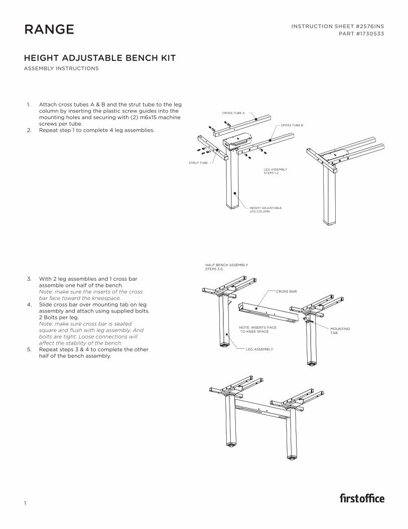
1. Attach cross tubes A & B and the strut tube to the leg column by inserting the plastic screw guides into the mounting holes and securing with (2) m6x15 machine screws per tube.
2. Repeat step 1 to complete 4 leg assemblies.
INSTRUCTION SHEET #2576INSPART #1730533
1
3. With 2 leg assemblies and 1 cross bar assemble one half of the bench. Note: make sure the inserts of the cross bar face toward the kneespace.
4. Slide cross bar over mounting tab on leg assembly and attach using supplied bolts. 2 Bolts per leg.Note: make sure cross bar is seated square and flush with leg assembly. And bolts are tight. Loose connections will affect the stability of the bench.
5. Repeat steps 3 & 4 to complete the other half of the bench assembly.
CROSS TUBE A
CROSS TUBE B
LEG ASSEMBLY STEPS 1-2
HEIGHT ADJUSTABLELEG COLUMN
STRUT TUBE
HALF BENCH ASSEMBLYSTEPS 3-5
LEG ASSEMBLY
MOUNTING TAB
CROSS BAR
NOTE: INSERTS FACE TO KNEE SPACE
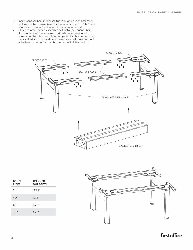
6. Insert spanner bars into cross tubes of one bench assembly half with notch facing downward and secure with m10x25 set screws. (See chart for Spanner Bar insertion depth)
7. Slide the other bench assembly half onto the spanner bars. If no cable carrier needs installed tighten remaining set screws and bench assembly is compelte. If cable carrier is to be installed leave second bench assembly half loose for final adjustament and refer to cable carrier installation guide.
SPANNER BARS
CROSS TUBES
CROSS TUBES
BENCH ASSEMBLY HALF
BENCH SIZES
SPANNER BAR DEPTH
54" 12.75"
60" 9.75"
66" 6.75"
72" 3.75"
INSTRUCTION SHEET # 2576INS
2
CABLE CARRIER
CABLE CARRIERASSEMBLY INSTRUCTIONS
CABLE CARRIEREXTRA FEATURES
RANGE
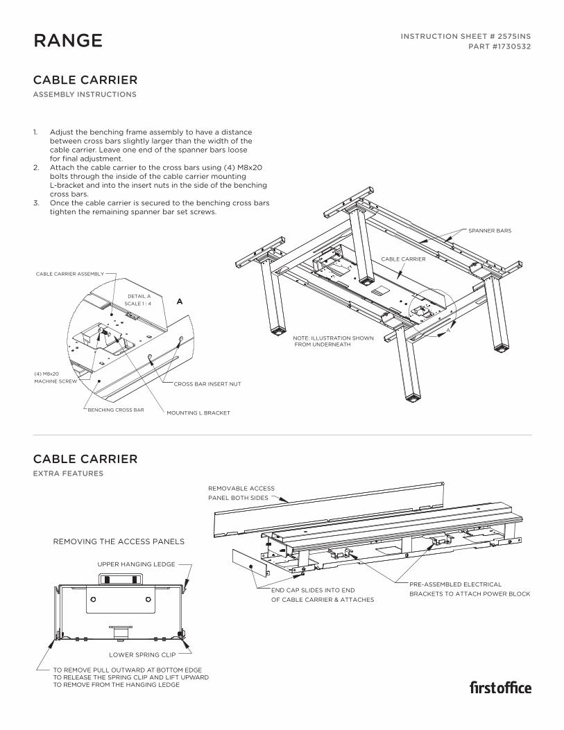
1. Adjust the benching frame assembly to have a distancebetween cross bars slightly larger than the width of thecable carrier. Leave one end of the spanner bars loosefor final adjustment.
2. Attach the cable carrier to the cross bars using (4) M8x20bolts through the inside of the cable carrier mountingL-bracket and into the insert nuts in the side of the benchingcross bars.
3. Once the cable carrier is secured to the benching cross barstighten the remaining spanner bar set screws.
INSTRUCTION SHEET # 2575INSPART #1730532
A
SPANNER BARS
CABLE CARRIER
NOTE: ILLUSTRATION SHOWN FROM UNDERNEATH
DETAIL A
SCALE 1 : 4
(4) M8x20
MACHINE SCREW CROSS BAR INSERT NUT
MOUNTING L BRACKETBENCHING CROSS BAR
CABLE CARRIER ASSEMBLY
A
LOWER SPRING CLIP
UPPER HANGING LEDGE
TO REMOVE PULL OUTWARD AT BOTTOM EDGE TO RELEASE THE SPRING CLIP AND LIFT UPWARD TO REMOVE FROM THE HANGING LEDGE
REMOVING THE ACCESS PANELS
PRE-ASSEMBLED ELECTRICAL
BRACKETS TO ATTACH POWER BLOCK
REMOVABLE ACCESS
PANEL BOTH SIDES
END CAP SLIDES INTO END
OF CABLE CARRIER & ATTACHES
WITH (2) M6X8 MACHINE SCREWS

GANGING TRAYASSEMBLY INSTRUCTIONS
RANGE
1. Insert end of ganging tray into open end of cable carrier of bench until it stopsagaints the built in spacing ledge.
2. Attach with (2) m4x20 bolts inserted from bottom side through mounting holesand secured with washer and nut from top side. Note: do not over tighten bolts.
3. Slide next bench into position inserting the other end of the ganging tray into theend of the cable carrier up to the spacing ledge and secure repeating step 2.
INSTRUCTION SHEET #2578INSPART #1730535
GANGING RAILASSEMBLY INSTRUCTIONS
RANGE
1. Insert one end of each thumb screw bracket into slot in bottom of rail andturn thumb screw to tighten. Leave loose for adjustment until benches arein final position.
2. Insert opposite end of one of the thumb screw brackets in the slot in thebottom of the benching cross bar. Once rail is centered in and flush toside of cross bar tighten the thumb screws to secure rail to bench.
3. Move the next bench in place tight up against the ganging rail, positioningthe rail centered and square to the benches cross bar and attach with thetumb screw bracket.
REMOVABLE ACCESS PANEL(LIFT OFF TO REMOVE)
3 CABLE ENTRY POLEATTACHING LOCATIONS
BUILT IN SPACING LEDGE
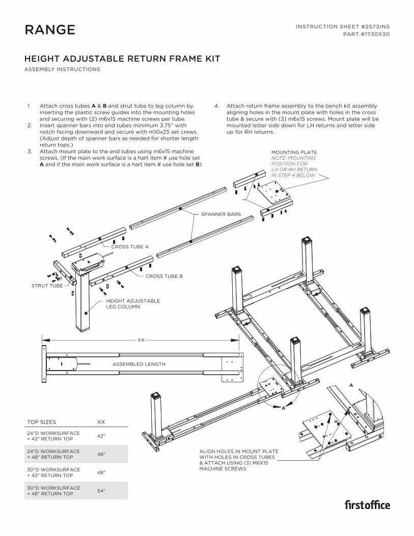
HEIGHT ADJUSTABLE RETURN FRAME KITASSEMBLY INSTRUCTIONS
RANGE
1. Attach cross tubes A & B and strut tube to leg column byinserting the plastic screw guides into the mounting holesand securing with (2) m6x15 machine screws per tube.
2. Insert spanner bars into end tubes minimum 3.75" withnotch facing downward and secure with m10x25 set crews.(Adjust depth of spanner bars as needed for shorter lengthreturn tops.)
3. Attach mount plate to the end tubes using m6x15 machinescrews. (If the main work surface is a hart item # use hole setA and if the main work surface is a hart item # use hole set B)
4. Attach return frame assembly to the bench kit assemblyaligning holes in the mount plate with holes in the crosstube & secure with (3) m6x15 screws. Mount plate will bemounted letter side down for LH returns and letter sideup for RH returns.
INSTRUCTION SHEET #2573INSPART #1730530
TOP SIZES XX
24"D WORKSURFACE + 42" RETURN TOP 42"
24"D WORKSURFACE + 48" RETURN TOP 48"
30"D WORKSURFACE + 42" RETURN TOP 48"
30"D WORKSURFACE + 48" RETURN TOP 54"
CROSS TUBE A
CROSS TUBE B
ASSEMBLED LENGTH
A
A
XX
SPANNER BARS
MOUNTING PLATENOTE: MOUNTING POSITION FORLH OR RH RETURN IN STEP 4 BELOW
STRUT TUBE
HEIGHT ADJUSTABLELEG COLUMN
ALIGN HOLES IN MOUNT PLATEWITH HOLES IN CROSS TUBES& ATTACH USING (3) M6X15MACHINE SCREWS
CABLE ENTRY POLEASSEMBLY INSTRUCTIONS
RANGE
1. Cable entry pole can be attached in 3 locationson the ganging tray or on either end of the cablecarrier to best fit as needed.
2. Align holes in housing with the holes in one of thepre-machined mounting location mentioned aboveusing (4) M4x10 self tapping machine screws.
3. Removable access panel allows easy access to runcables. Remove by pulling outward. Install by pushingpanel inward inside the housing until it bottoms outon the built in stops.
INSTRUCTION SHEET #2574INSPART #1730531
HOUSING
REMOVABLE ACCESS PANEL
BUILT IN STOP
(4) M4X10 SCREWS
2 CABLE ENTRY POLE MOUNTING LOCATIONS
CABLE CARRIER
3 CABLE ENTRY POLEMOUNTING LOCATIONS
GANGING TRAY
RANGE
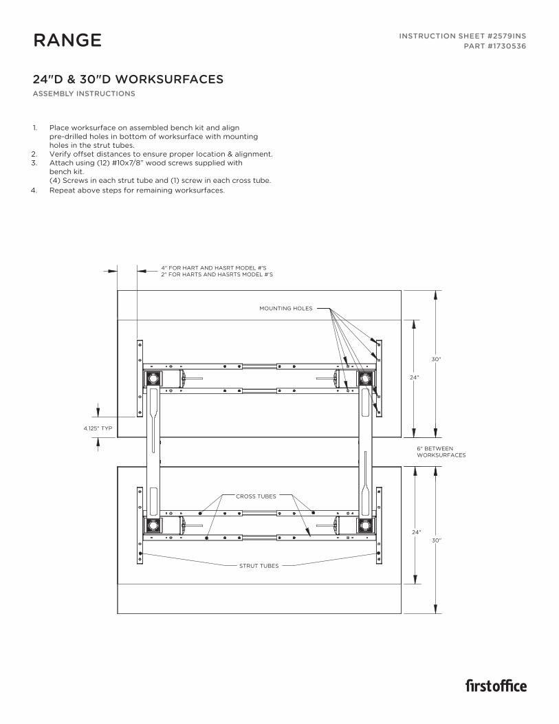
24"D & 30"D WORKSURFACESASSEMBLY INSTRUCTIONS
1. Place worksurface on assembled bench kit and alignpre-drilled holes in bottom of worksurface with mounting holes in the strut tubes.
2. Verify offset distances to ensure proper location & alignment.3. Attach using (12) #10x7/8” wood screws supplied with
bench kit.(4) Screws in each strut tube and (1) screw in each cross tube.
4. Repeat above steps for remaining worksurfaces.
INSTRUCTION SHEET #2579INSPART #1730536
MOUNTING HOLES
STRUT TUBES
24"
6" BETWEEN WORKSURFACES
4.125" TYP
24"
30"
4" FOR HART AND HASRT MODEL #'S 2" FOR HARTS AND HASRTS MODEL #'S
30"
CROSS TUBES
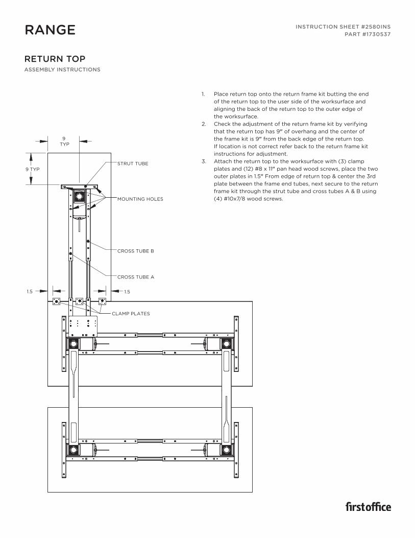
RETURN TOPASSEMBLY INSTRUCTIONS
RANGE
1. Place return top onto the return frame kit butting the endof the return top to the user side of the worksurface andaligning the back of the return top to the outer edge ofthe worksurface.
2. Check the adjustment of the return frame kit by verifyingthat the return top has 9" of overhang and the center ofthe frame kit is 9" from the back edge of the return top.If location is not correct refer back to the return frame kitinstructions for adjustment.
3. Attach the return top to the worksurface with (3) clampplates and (12) #8 x 11" pan head wood screws, place the twoouter plates in 1.5" From edge of return top & center the 3rdplate between the frame end tubes, next secure to the returnframe kit through the strut tube and cross tubes A & B using(4) #10x7/8 wood screws.
INSTRUCTION SHEET #2580INSPART #1730537
9 TYP
STRUT TUBE
CROSS TUBE B
CROSS TUBE A
CLAMP PLATES
MOUNTING HOLES
1.5
9 TYP
1.5
WORKSURFACES EDGE MODESTYASSEMBLY INSTRUCTIONS
RANGE
1. Attach brackets (Item # WEBKT-1, WEBKT-2, WEBKT-3)to modesty panel.
2. Tighten screws.3. Attach assembled modesty panel to approach edge of
worksurface.4. Tighten screws.
INSTRUCTION SHEET #2582INSPART #1730545
TOP EDGE
TIGHTEN
RAIL MOUNTED PRIVACY SCREENASSEMBLY INSTRUCTIONS
RANGE
1. Remove the nut and washer from each standoff.2. Place the screen onto the Cable Carrier aligning
the bolts in each standoff with the holes in theCable Carrier top rail.
3. From the bottom side of the Cable Carrierthrough the access hole replace the washerand nut onto each standoff bolt and tighten.
INSTRUCTION SHEET #2581INSPART #1730538
ASSEMBLED BENCH KIT W/ CABLE CARRIER
ATTACHING HARWARE
PRIVACY SCREEN W/ STANDOFFS
BOTTOM VIEW
ACCESS HOLE IN BOTTOM OF CABLE CARRIER
HEIGHT ADJUSTABLE TABLEASSEMBLY INSTRUCTIONS
RANGE
1. Assemble the foot to the leg column with 4 M6x15 hex socket cap screws.2. Install the leveling glides into the bottom of the foot.3. Repeat above steps to create a “LH” and a “RH” leg assembly.
INSTRUCTION SHEET #2586INSPART #1730739
TOP SIZESSPANNER BAR
INSERTION DEPTH
48" 20.125"
54" 20.125"
60" 16"
66" 14.5"
72" 11.75"
M6X15 HEX SOCKET HEAD CAP SCREW
LEVELING GLIDES
HEIGHT ADJUSTABLELEG COLUMN
FOOT
RH FOOTASSEMBLY
CROSS TUBE
SHORT MOUNTING TUBENOTE: NOT USED ON 48"& 54" TOPS
SPANNER BARS
M10X25 SET SCREWS
4. Slide the short mounting tubes on to the spanner bars, positioning them in the center of the spanner bars and securing by tightening the M10X25 set screws.
5. Referencing the insertion chart, slide a cross tube on each end of the spanner bars in the orientation as shown in the image and secure cross tubes by tightening the M10X25 set scews.
RANGE INSTRUCTION SHEET #2586INSPART #1730739
HEIGHT ADJUSTABLE TABLEASSEMBLY INSTRUCTIONS CONTINUED
6. Insert screw guides into end & cross tubes.7. Attach cross tube assemblies & end tubes to leg
assembly motor housings as shown using (2) M6X15 cap screws per tube.
8. Insert end caps into each end of both end tubes.
RH LEGASSEMBLY
SCREWGUIDE
ENDCAP
M6X15 HEX SOCKETHEAD CAP SCREW
LH LEGASSEMBLY
END TUBE
CROSS TUBE ASSEMBLY
9. Position top upside down on a protective surface.10. Locate frame centered on top, side to side, and off the back edge
according to dimension “x” in the chart.11. Attach frame to top with (4) wood screws in each end tube.12. Locate 1 u-clamp on each cross bar approximately 14" from end of
frame and attach with (2) wood screws per clamp.13. For 60", 66", and 72" tops, place 1 u-clamp centered on each short
mounting tube and attach with (2) wood crews per clamp.
END TUBE U-CLAMP14"
X
TOP DEPTH X
24" 2.125"
30" 5.125"