digital imaging and communications in ... - · pdf filesupplement 205 - encapsulation of stl...
TRANSCRIPT

Digital Imaging and Communications in Medicine (DICOM)
Supplement 205: DICOM Encapsulation of STL Models for 3D Manufacturing
Prepared by:
DICOM Standards Committee, Working Group 17
1300 N. 17th Street Suite 1752
Rosslyn, Virginia 22209 USA
VERSION: DRAFT-21 December 6, 2017
This is a draft document. Do not circulate, quote, or reproduce it except with the approval of NEMA.
Developed pursuant to DICOM Work Item 2017-04-E
Supplement 205 - Encapsulation of STL Models for 3D Manufacturing Page 2
Table of Contents
Scope and Field of Application ....................................................................................................................... 3
Changes to NEMA Standards Publication PS 3.2-2018x ............................................................................... 6
Changes to NEMA Standards Publication PS 3.3-2018x ............................................................................... 7 A.X.3 Encapsulated STL Information Object Definition ........................................................... 8 5
A.X.3.1 Encapsulated STL IOD Description ..................................................................... 8 A.X.3.2 Encapsulated STL Entity-Relationship Model ...................................................... 8 A.X.3.3 Encapsulated STL IOD Module Table .................................................................. 8 A.X.3.4 Encapsulated STL IOD Content Constraints........................................................ 8
C.7.3.1.1 General Series Attribute Descriptions ................................................................................ 9 10
C.7.3.1.1.1 Modality ................................................................................................................. 9 C.24.2 Encapsulated Document Module ................................................................................... 9 C.24.Y Manufacturing 3D Model IOD Module .......................................................................... 12
Changes to NEMA Standards Publication PS 3.4-2018x ............................................................................. 14
B.5 STANDARD SOP CLASSES .......................................................................................................... 14 15
Changes to NEMA Standards Publication PS 3.6-2018x ............................................................................. 15
Annex A Registry of DICOM unique identifiers (UID) (Normative) ....................................................... 15
Changes to NEMA Standards Publication PS 3.16-2018x ........................................................................... 17
CID 7XX1 MODEL DOCUMENT TITLES .............................................................................................. 17
CID 7XX2 PURPOSE OF REFERENCE TO PREDECESSOR 3D MODEL ......................................... 18 20
Table CID 7XX2. Purpose of Reference to Predecessor 3D Model ................................................ 18 CID 7XX3 MODEL SCALE UNITS ......................................................................................................... 18
Table CID 7XX3. 3D Model Scale Units .......................................................................................... 18 Changes to NEMA Standards Publication PS 3.17-2018x ........................................................................... 20
HHHH Encapsulated STL (Informative) ........................................................................................................ 20 25

Supplement 205 - Encapsulation of STL Models for 3D Manufacturing Page 3
Scope and Field of Application
This supplement adds a new DICOM IOD to encapsulate Stereolithography (STL) 3D model file formats 30
(see StereoLithography Interface Specification, 3D Systems, Inc., October 1989).
The new IOD allows 3D manufacturing models to be exchanged between various types of equipment using DICOM messages. This adds the ability to store, query and retrieve 3D models as DICOM objects. Updates are addressed by storing new instances, with reference back to earlier instances.
The 3D model files are a type of document that contains geometric instructions on how an object could be 35
created by a 3D printer, milling machine, or other type of device capable of manufacturing a physical object.
To exchange these 3D models in an efficient manner in an imaging environment, especially as part of patient care planning and the patient’s imaging record, it is useful to be able to “wrap” these model documents in a DICOM container. 40
Additionally, the identity of the patient (and any source image series) of the encapsulated 3D models can be ascertained through the attributes that the DICOM information model adds on top of the 3D model’s general purpose geometric information.
Since its introduction, the STL file format has been used for a variety of applications, including 3D manufacturing. STL is the most prevalent file format in the 3D printing community and enjoys wide support 45
by existing systems.
STL supports both an ASCII and binary encoding. In the interest of simplicity and minimizing SOP Instance size, only the binary encoding of STL is supported for DICOM encapsulation. The binary STL format is
simple enough to be described here as the following IEEE little-endian byte sequence:
80 Character Header = Not interpreted 50
UINT32 = Number of triangles
For each triangle
REAL32 x 3 = Normal vector coordinates
REAL32 x 3 = Vertex 1 coordinates
REAL32 x 3 = Vertex 2 coordinates 55
REAL32 x 3 = Vertex 3 coordinates
UINT16 = Reserved value. Always set to Zero in practice
end
OPEN ISSUES TABLE
# Question Comments
5 Would inclusion of selected attributes of the implant description module be beneficial for 3D models that are intended to be implants?
Still need expert input on this.
6 Would there be meaningful benefit from incorporating further implant detail via the use implant defined terms, code sets, or other
Authors left out such level of detail in the interest of simplicity. However, a hip assembly can contain 20 parts. It is possible that it would

Supplement 205 - Encapsulation of STL Models for 3D Manufacturing Page 4
# Question Comments
encoding (e.g. CID 73xx family)? be useful to identify which part is represented by which model. However, existing means of identification (e.g. Document Title) may be sufficient for real-world use.
7 Is the existing use of Frame-of-Reference adequate to handle registration in all cases?
Authors believe it does. Also, follows current conventions of 3D modeling software (model uses coordinate system of primary source series).
8 The Model Usage attribute does not distinguish between different types of instrument guides. Is there actual value to adding additional granularity (e.g. distinguishing needle, blade, drill guides) sufficient to justify additional complexity?
The additional granularity was initially included, but later omitted by the authors in the interest of simplicity.
9 The Model Usage attribute does not distinguish between different levels of permanence for implants. Is there actual value to adding additional granularity (e.g. distinguishing absorbable, removable, and permanent implants) to justify additional complexity?
The additional granularity was initially included, but later omitted by the authors in the interest of simplicity.
10 The Module Usage attribute is included to help filter when multiple models are returned a query, routing for handling, etc. Are the values selected sufficient for these use cases?
11 The use of the existing Referenced SOP Class UID attribute to identify the source images implies that if 10,000 images were used to construct a model, there would be 10,000 individual UIDs recorded in the model’s DICOM object. Is this reasonable given the goal was simply to identify the source series, not individual images? Or is reference to a small number of representative images sufficient for the goal of supporting linked comparison? Our options thus appear to be (a) require only a small number of representative images from each source series or (b) define a different attribute that represents a series-level reference.
This is not an issue if the Enhanced CT or MR images are the source for the model (as was used in the examples).
12 Is using only metric units from micrometers to meters sufficient to identify any scale in routine use for medical and non-destructive-testing purposes?
We only used metric units for patient safety reasons and to match current clinical practice (which appears to universally use either mm or m).
We created a new context group specifically for 3D printing scale (7xxz). This ensures that other units could be added in the future should a new use case arise.

Supplement 205 - Encapsulation of STL Models for 3D Manufacturing Page 5
# Question Comments
13 Related to question 12. Is a multiplication factor for unit scale also required?
For example, there is no way to specify that the unit scale of the model is 2.54 mm. Instead the creator of the STL would need to divide all coordinates in the file by 2.54 and specify the unit scale as mm.
14 What other derivations need to be added to LOINC for 3D print models? Currently only CT and MR derived models can be coded using LOINC references. Also, what is the best way to capture fused multi-modality fusion models in a single LOINC code?
Some individuals are working with 3D printing from ultrasound. So, we assume it should be added to LOINC.
15 Some 3D printing workflows in medicine may desire a sign-off on a model by a biomedical engineer. Should the proposed DICOM object’s definition be extended to capture the identity of this individual in such workflows?
60
CLOSED ISSUES TABLE
# Question Comments
1 Should other formats (OBJ, X3D, 3MF) be referenced in this IOD also?
No, they will be added as separate IODs at a future date, if required. Other 3D model file formats with additional capabilities beyond STL may be addressed in future supplements, but are beyond the scope of this document (other than that these are expected to make use of the new Manufacturing 3D Model introduced below).
2 Should ASCII STL be supported? No, because it is verbose and inefficient. Essentially all systems that can accept STL can handle binary. There is no need to complicate the DICOM standard with an additional variant.
3 Should MIME elements be identified by name, in order to avoid future issues if additional elements of overlapping types are added later?
No longer relevant due to change to use of Icon Sequence.
4 Is handling the preview image as an MIME-embedded JPEG the best option?
No. An Icon Sequence was felt to be more appropriate to the needs, clearer to document, and simpler to implement.

Supplement 205 - Encapsulation of STL Models for 3D Manufacturing Page 6
Changes to NEMA Standards Publication PS 3.2-2018x
Digital Imaging and Communications in Medicine
Part 2: Conformance 65
Item: Add to table A.1-2 categorizing SOP Classes:
The SOP Classes are categorized as follows: 70
Table A.1-2 UID VALUES
UID Value UID NAME Category
… … …
1.2.840.10008.5.1.4.1.1.xxx Encapsulated STL Storage SOP Class
Transfer
… … …

Supplement 205 - Encapsulation of STL Models for 3D Manufacturing Page 7
Changes to NEMA Standards Publication PS 3.3-2018x 75
Digital Imaging and Communications in Medicine (DICOM)
Part 3: Information Object Definitions
Modify Section A.1.4 Overview of the Composite IOD Module Content – Insert Encapsulated STL
Table A.1-3COMPOSITE INFORMATION OBJECT MODULES OVERVIEW – MORE NON-IMAGES 80
IODs
Modules … Enc
STL …
Patient M
Patient Summary
Clinical Trial Subject U
General Study M
Patient Study U
Clinical Trial Study U
Study Content
Encapsulated Document Series M
Clinical Trial Series U
…
General Equip. M
Enhanced General Equip. M
…
Encapsulated Document M
…
SOP Common M
…
Manufacturing 3D Model M
Supplement 205 - Encapsulation of STL Models for 3D Manufacturing Page 8
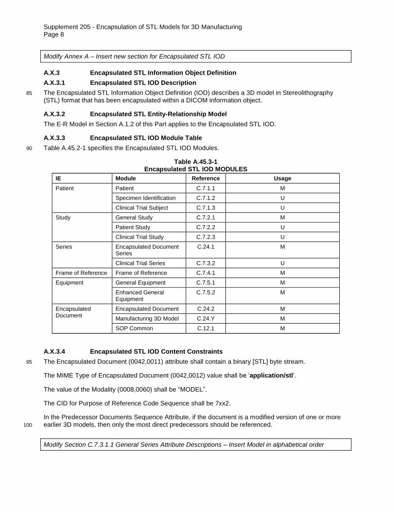
Modify Annex A – Insert new section for Encapsulated STL IOD
A.X.3 Encapsulated STL Information Object Definition
A.X.3.1 Encapsulated STL IOD Description
The Encapsulated STL Information Object Definition (IOD) describes a 3D model in Stereolithography 85
(STL) format that has been encapsulated within a DICOM information object.
A.X.3.2 Encapsulated STL Entity-Relationship Model
The E-R Model in Section A.1.2 of this Part applies to the Encapsulated STL IOD.
A.X.3.3 Encapsulated STL IOD Module Table
Table A.45.2-1 specifies the Encapsulated STL IOD Modules. 90
Table A.45.3-1 Encapsulated STL IOD MODULES
IE Module Reference Usage
Patient Patient C.7.1.1 M
Specimen Identification C.7.1.2 U
Clinical Trial Subject C.7.1.3 U
Study General Study C.7.2.1 M
Patient Study C.7.2.2 U
Clinical Trial Study C.7.2.3 U
Series Encapsulated Document Series
C.24.1 M
Clinical Trial Series C.7.3.2 U
Frame of Reference Frame of Reference C.7.4.1 M
Equipment General Equipment C.7.5.1 M
Enhanced General Equipment
C.7.5.2 M
Encapsulated Document
Encapsulated Document C.24.2 M
Manufacturing 3D Model C.24.Y M
SOP Common C.12.1 M
A.X.3.4 Encapsulated STL IOD Content Constraints
The Encapsulated Document (0042,0011) attribute shall contain a binary [STL] byte stream. 95
The MIME Type of Encapsulated Document (0042,0012) value shall be ‘application/stl’.
The value of the Modality (0008,0060) shall be “MODEL”.
The CID for Purpose of Reference Code Sequence shall be 7xx2.
In the Predecessor Documents Sequence Attribute, if the document is a modified version of one or more earlier 3D models, then only the most direct predecessors should be referenced. 100
Modify Section C.7.3.1.1 General Series Attribute Descriptions – Insert Model in alphabetical order

Supplement 205 - Encapsulation of STL Models for 3D Manufacturing Page 9
C.7.3.1.1 General Series Attribute Descriptions
C.7.3.1.1.1 Modality
Defined Terms: … 105
MODEL Model for 3D Manufacturing
…
Modify Annex C.24 – Clarifications for Encapsulated STL 3D Manufacturing 3D Model
C.24.2 Encapsulated Document Module
Table C.24-2 defines the Encapsulated Document Attributes. 110
Table C.24-2 Encapsulated Document Module Attributes
Attribute Name Tag Type Attribute Description
Instance Number (0020,0013) 1 A number that identifies this SOP Instance. The value shall be unique within a series.
Content Date (0008,0023) 2 The date the document content creation was started.
Content Time (0008,0033) 2 The time the document content creation was started.
Acquisition DateTime (0008,002A) 2 The date and time that the original generation of the data in the document started.
Image Laterality (0020,0062) 3 Laterality of the (possibly paired) body part that is the subject of the encapsulated document.
Enumerated Values:
R right
L left
U unpaired
B both left and right
If the IOD is an Encapsulated STL then values for the laterality attribute shall refer to the intended placement of the created object regardless of how it was generated (see also Model Mirroring, C.24.Y.2).
Burned In Annotation (0028,0301) 1 Indicates whether or not the encapsulated document contains sufficient burned in annotation to identify the patient and date the data was acquired.
Enumerated Values:
YES
NO
Identification of patient and date as text in an encapsulated document (e.g., in an XML attribute or element) is equivalent to "burned in annotation". A de-identified document may use the value NO.
If the document is a 3D manufacturing model, the presence of identifying information embossed or

Supplement 205 - Encapsulation of STL Models for 3D Manufacturing Page 10
engraved on any part of the model shall be indicated by a value of YES.
Recognizable Visual Features
(0028,0302)
3 Indicates whether or not the image instance contains sufficiently recognizable visual features to allow the image instance or a reconstruction from a set of images instances
to identify the patient.
Enumerated Values:
YES
NO
If this Attribute is absent, then the image instance may or
may not contain recognizable visual features.
Source Instance Sequence
(0042,0013) 1C A sequence that identifies some or all of the Instances that
were used to derive the encapsulated document.
One or more Items shall be included in this Sequence. Instances may be drawn from different studies.
Required if derived from one or more DICOM Instances (e.g. 3D models derived from image series).
May be present otherwise.
>Include Table 10-11 “SOP Instance Reference Macro Attributes”
>Purpose of Reference Code Sequence
(0040,A170) 3 Describes the purpose for which the reference is made, that is what role the source instances played in the derivation of this encapsulated document
Only a single Item is permitted in this Sequence.
>>Include Table 8.8-1 “Code Sequence Macro Attributes”
Defined CID 7013 “Non-Image Source Instance Purposes of Reference”.
Document Title (0042,0010) 2 The title of the document.
Note
In the case of a PDF encapsulated document, this may be the value of the "Title" entry in the "Document Information Directory" as encoded in the PDF data.
Concept Name Code Sequence
(0040,A043) 2 A coded representation of the document title.
Zero or one Item shall be included in this Sequence.
>Include Table 8.8-1 “Code Sequence Macro Attributes”
For Encapsulated STL IODs the Baseline CID is 7xx1 “3D Model Document Titles”.
For all other Encapsulated documents use the Baseline CID 7020 “Document Titles”.
Document Class Code Sequence
(0040,E008) 3 Additional classifications of the document, beyond the title represented in Concept Name Code Sequence. May be eEquivalent to HL7 v2.x TXA-2.
One or more Items are permitted in this Sequence.
>Include Table 8.8-1 “Code Sequence Macro Attributes”
No Baseline CID is defined.
Verification Flag (0040,A493) 3 Indicates whether the Encapsulated Document is Verified.
Enumerated Values:
UNVERIFIED Not attested by a legally accountable person.
VERIFIED Attested to (signed) by a Verifying Observer or

Supplement 205 - Encapsulation of STL Models for 3D Manufacturing Page 11
Legal Authenticator named in the document, who is accountable for its content.
HL7 Instance Identifier (0040,E001) 1C Instance Identifier of the encapsulated HL7 Structured Document, encoded as a UID (OID or UUID), concatenated with a caret ("^") and Extension value (if Extension is present in Instance Identifier).
Required if encapsulated document is a CDA document.
Predecessor Documents Sequence Attribute
(0040,A360) 3 References to SOP Instances whose content has been wholly or partially included in this document with or without modification.
One or more Items are permitted in this sequence.
>Include Table C.17-3 'Hierarchical SOP Instance Reference Macro'
Defined CID for the Purpose of Reference Code Sequence in the Hierarchical SOP Instance Reference Macro is:
For an Encapsulated STL IOD, CID 7xx2 “Purpose of Reference to Predecessor 3D Model”; Otherwise, CID 7009 “Purpose of Reference to Predecessor Report”.
Identical Documents Sequence
(0040,A525) 3 Duplicates of this document, stored with different SOP Instance UIDs.
One or more Items are permitted in this sequence.
See Section C.17.2.2 for further explanation.
>Include Table C.17-3 “Hierarchical SOP Instance Reference Macro Attributes”
MIME Type of Encapsulated Document
(0042,0012) 1 The type of the encapsulated document stream described using the MIME Media Type (see RFC 2046).
List of MIME Types (0042,0014) 1C MIME Types of subcomponents of the encapsulated document.
Required if the encapsulated document incorporates subcomponents with MIME types different than the primary MIME Type of the encapsulated document.
Encapsulated Document (0042,0011) 1 Encapsulated Document stream, containing a document encoded according to the MIME Type.
Note
1. One could distinguish four stages in the creation of the Encapsulated Document Object, identified by the following Attributes: 115
1. Measurement and/or data collection, identified by Acquisition DateTime (0008,002A) in the Encapsulated Document Module.
2. Creation of the original documentation of the data collection, identified by Content Date (0008,0023) and Content Time (0008,0033).
3. Rendering of the original documentation into the format that will be encapsulated, e.g., a PDF 120
document. The rendering time is not captured by any DICOM Attribute, but may be encoded in the rendering.
4. Encapsulation of the rendering into a DICOM Object, identified by Instance Creation Date (0008,0012) and Instance Creation Time (0008,0013) in the SOP Common Module.
2. DICOM does not specify requirements for consistency between DICOM attribute values and data in the 125
encapsulated document. It is expected that applications will ensure consistency in a manner appropriate to the application. For example, the Patient ID in an encapsulated CDA document may be that of a different institution, which originated the document, and it may be appropriate for the DICOM attribute value to be different.
130

Supplement 205 - Encapsulation of STL Models for 3D Manufacturing Page 12
Modify PS3.3 Annex C.24 to insert definition of a new 3D Manufacturing module and associated defined terms.
C.24.Y Manufacturing 3D Model IOD Module
Table C.24.Y-1 defines attributes specific to models used in medical 3D manufacturing.
Table C.24.Y-1 135
Manufacturing 3D Model IOD Module Attributes
Attribute Name Tag Type Attribute Description
Measurement Units Code Sequence
(0040,08EA) 1 Units of distance for the coordinate system for the encapsulated STL file
Only a single Item shall be included in this Sequence.
>Include Table 8.8-1 “Code Sequence Macro Attributes”
Defined CID 7xx3 “Model Scale Units”.
Model Modification (aaa1,bbb1) 3 Specifies whether a modification of the observed anatomy (other than mirroring) was used to create the model (e.g. simulating an expected surgical result). In the negative, the model follows the observed patient anatomy in the source data.
Enumerated Values:
YES
NO
Model Mirroring (aaa1,bbb2) 3 Specifies whether mirroring of anatomy from the other side of the patient was used to create the model
Enumerated Values:
YES
NO
Model Usage (aaa1,bbb3) 3 Specifies the use for which the manufactured object is intended.
See Section C.24.Y.1 for Defined Terms
Icon Image Sequence (0088,0200) 3 A preview image representing the rendered model.
See Section C.7.6.1.1.6 for further explanation
C.24.Y.1 Model Usage
Model Usage (aaa1,bbb1) is used to distinguish similar-appearing models by providing the original intent of the designer. The model may be used for other purposes. 140
Defined Terms:
EDUCATION Modeled object is intended for patient or care-giver education / informed
consent, or training residents and fellows
DIAGNOSIS Modeled object is intended to be used to assist with diagnosis
PLANNING Modeled object is intended to be used to assist with pre-operative 145
procedure planning

Supplement 205 - Encapsulation of STL Models for 3D Manufacturing Page 13
INSTRUMENT Modeled object is intended to be used as a patient-matched intra-operative tool during a medical procedure (e.g. drill and cutting guides, radiation shielding, plate bending template)
PROSTHETIC Modeled object is intended to be used as a fully external 150
prosthetic/orthotic.
IMPLANT Modeled object is intended to be used as a wholly or partially internal
implant.
QUALITY CONTROL Modeled object is intended to be used for quality control purposes (e.g. an
imaging phantom, calibration model). 155
SIMULATION Modeled object is intended to be used for simulation and/or practice of a surgery or other medical procedure. Shall not be used for patient-matched simulation (as this would be covered by DIAGNOSIS or PLANNING)
160

Supplement 205 - Encapsulation of STL Models for 3D Manufacturing Page 14
Changes to NEMA Standards Publication PS 3.4-2018x 165
Digital Imaging and Communications in Medicine (DICOM)
Part 4: Service Class Specifications
Modify Annex B.5 Standard SOP Classes – add new item.
B.5 STANDARD SOP CLASSES 170
Table B.5-1STANDARD SOP CLASSES
SOP Class Name SOP Class UID IOD (See PS 3.3)
…
Encapsulated STL Storage 1.2.840.10008.5.1.4.1.1.xxx Encapsulated STL IOD
…
175

Supplement 205 - Encapsulation of STL Models for 3D Manufacturing Page 15
Changes to NEMA Standards Publication PS 3.6-2018x
Digital Imaging and Communications in Medicine (DICOM)
Part 6: Data Dictionary
180
Modify PS3.6 Table 6-1. Registry of DICOM Data Elements to add the following elements in the correct order.
Table 6-1. Registry of DICOM Data Elements
Tag Name Keyword VR VM
… … … … …
(aaa1,bbb1) Model Modification ModelModification CS 1
(aaa1,bbb2) Model Mirroring ModelMirroring CS 1
(aaa1,bbb3) Model Usage ModelUsage CS 1
…
185
Modify PS3.6 Annex A Registry of DICOM unique identifiers (UID) – add new item.
Annex A Registry of DICOM unique identifiers (UID) (Normative)
Table A-1 lists the UID values that are registered and used throughout the Parts of the DICOM Standard. This central registry ensures that when additional UIDs are assigned, non-duplicate values are assigned. 190
Table A-1
UID VALUES
UID Value UID NAME UID TYPE Part
…
1.2.840.10008.5.1.4.1.1.xxx Encapsulated STL Storage SOP Class PS 3.4
…

Supplement 205 - Encapsulation of STL Models for 3D Manufacturing Page 16

Supplement 205 - Encapsulation of STL Models for 3D Manufacturing Page 17
Changes to NEMA Standards Publication PS 3.16-2018x 195
Digital Imaging and Communications in Medicine
Part 16: Content Mapping Resource
Addition to PS3.16 Content Mapping Resource – Modify CID 29 Acquisition Modality to include MODEL in the correct location.
CID 29 Acquisition Modality 200
This Context Group includes codes that may be used to identify an image or waveform acquisition modality, as used in Attribute Modality (0008,0060) of a Modality Worklist Scheduled Procedure Step or a Composite SOP Instance (see PS3.3). It generally corresponds to a class of diagnostic equipment, or to a specific acquisition function or technique in a device. This Context Group may be used as the value set for HL7 v2 Table 0259 (see HL7 v2.6 Chapter 8 Section 8.8.8.47). 205
Note
This Context Group is not the complete set of codes that may appear in the Attribute Modality (0008,0060); these are only the codes associated with orderable acquisition processes (not post-processing).
Type: Extensible 210
Version: YYYYMMDD UID: 1.2.840.10008.6.1.19
Table CID 29. Acquisition Modality
Coding Scheme Designator Code Value Code Meaning
… … …
DCM MODEL Model for 3D Manufacturing
… … …
215
Addition to PS3.16 Content Mapping Resource – Add 3 new CIDs.
CID 7XX1 MODEL DOCUMENT TITLES
Type: Extensible Version: YYYYMMDD UID: 1.2.840.10008.6.1.xx1 220
Context Group ID 7xx1 comprises all document names (i.e., terms with Scale "DOC") within the 3D Printed Model component of the LOINC coding scheme. The Coding Scheme Designator shall be LN. The terms
included in the table below may not constitute the complete list; see the LOINC coding scheme.

Supplement 205 - Encapsulation of STL Models for 3D Manufacturing Page 18
Note 225
The LOINC coding scheme can be found at http://www.regenstrief.org/loinc.
Table CID 7XX1. MODEL DOCUMENT TITLES
Coding Scheme Designator
Code Value Code Meaning
LN 85041-2 This term can be used to order an MR-based 3D printed model and can also be associated with the file that is generated in response to that order when the file is stored.
LN 85040-4 This term can be used to order a CT-based 3D printed model and can also be associated with the file that is generated in response to that order when the file is stored.
230
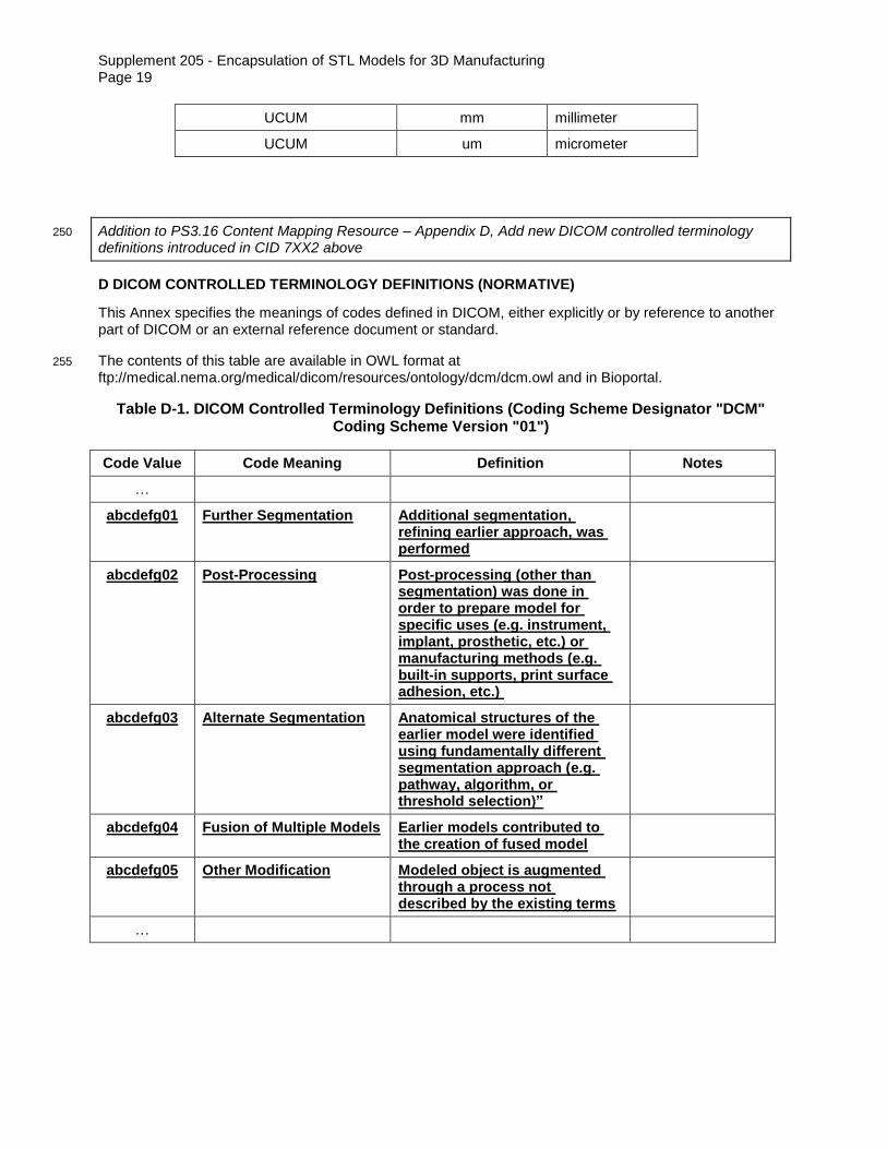
CID 7XX2 PURPOSE OF REFERENCE TO PREDECESSOR 3D MODEL
Type: Extensible Version: YYYYMMDD UID: 1.2.840.10008.6.1.xx2 235
Context Group ID 7xx2 comprises all reasons that a 3D model might be created by modifying an earlier one.
Table CID 7XX2. Purpose of Reference to Predecessor 3D Model
Coding Scheme Designator Code Value Code Meaning
DCM abcdefg01 Further Segmentation
DCM abcdefg02 Post-Processing
DCM abcdefg03 Alternate Segmentation
DCM abcdefg04 Fusion of Multiple Models
DCM abcdefg05 Other Modification
240
CID 7XX3 MODEL SCALE UNITS
Type: Extensible Version: YYYYMMDD UID: 1.2.840.10008.6.1.xx3
245
Context Group ID 7xx3 comprises all valid scale units that may be used in a 3D model.
Table CID 7XX3. 3D Model Scale Units
Coding Scheme Designator Code Value Code Meaning
UCUM m meter
UCUM cm centimeter
Supplement 205 - Encapsulation of STL Models for 3D Manufacturing Page 19
UCUM mm millimeter
UCUM um micrometer
Addition to PS3.16 Content Mapping Resource – Appendix D, Add new DICOM controlled terminology 250
definitions introduced in CID 7XX2 above
D DICOM CONTROLLED TERMINOLOGY DEFINITIONS (NORMATIVE)
This Annex specifies the meanings of codes defined in DICOM, either explicitly or by reference to another part of DICOM or an external reference document or standard.
The contents of this table are available in OWL format at 255
ftp://medical.nema.org/medical/dicom/resources/ontology/dcm/dcm.owl and in Bioportal.
Table D-1. DICOM Controlled Terminology Definitions (Coding Scheme Designator "DCM" Coding Scheme Version "01")
Code Value Code Meaning Definition Notes
…
abcdefg01 Further Segmentation Additional segmentation, refining earlier approach, was performed
abcdefg02 Post-Processing Post-processing (other than segmentation) was done in order to prepare model for specific uses (e.g. instrument, implant, prosthetic, etc.) or manufacturing methods (e.g. built-in supports, print surface adhesion, etc.)
abcdefg03 Alternate Segmentation Anatomical structures of the earlier model were identified using fundamentally different segmentation approach (e.g. pathway, algorithm, or threshold selection)”
abcdefg04 Fusion of Multiple Models Earlier models contributed to the creation of fused model
abcdefg05 Other Modification Modeled object is augmented through a process not described by the existing terms
…
Supplement 205 - Encapsulation of STL Models for 3D Manufacturing Page 20
Changes to NEMA Standards Publication PS 3.17-2018x 260
Digital Imaging and Communications in Medicine
Part 17: Informative
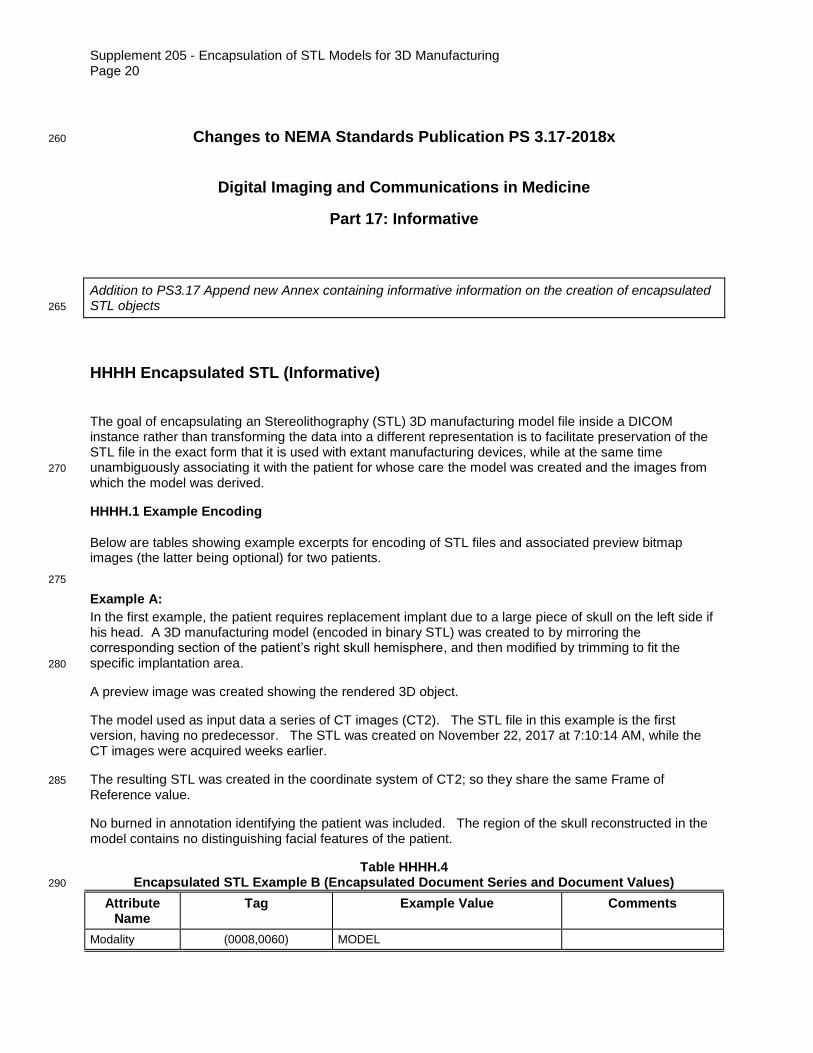
Addition to PS3.17 Append new Annex containing informative information on the creation of encapsulated STL objects 265
HHHH Encapsulated STL (Informative)
The goal of encapsulating an Stereolithography (STL) 3D manufacturing model file inside a DICOM instance rather than transforming the data into a different representation is to facilitate preservation of the STL file in the exact form that it is used with extant manufacturing devices, while at the same time unambiguously associating it with the patient for whose care the model was created and the images from 270
which the model was derived.
HHHH.1 Example Encoding
Below are tables showing example excerpts for encoding of STL files and associated preview bitmap images (the latter being optional) for two patients.
275
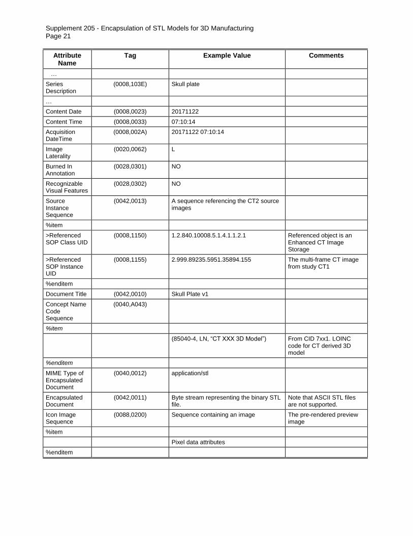
Example A:
In the first example, the patient requires replacement implant due to a large piece of skull on the left side if his head. A 3D manufacturing model (encoded in binary STL) was created to by mirroring the corresponding section of the patient’s right skull hemisphere, and then modified by trimming to fit the specific implantation area. 280
A preview image was created showing the rendered 3D object.
The model used as input data a series of CT images (CT2). The STL file in this example is the first version, having no predecessor. The STL was created on November 22, 2017 at 7:10:14 AM, while the CT images were acquired weeks earlier.
The resulting STL was created in the coordinate system of CT2; so they share the same Frame of 285
Reference value.
No burned in annotation identifying the patient was included. The region of the skull reconstructed in the model contains no distinguishing facial features of the patient.
Table HHHH.4 Encapsulated STL Example B (Encapsulated Document Series and Document Values) 290
Attribute Name
Tag Example Value Comments
Modality (0008,0060) MODEL
Supplement 205 - Encapsulation of STL Models for 3D Manufacturing Page 21
Attribute Name
Tag Example Value Comments
…
Series Description
(0008,103E) Skull plate
…
Content Date (0008,0023) 20171122
Content Time (0008,0033) 07:10:14
Acquisition DateTime
(0008,002A) 20171122 07:10:14
Image Laterality
(0020,0062) L
Burned In Annotation
(0028,0301) NO
Recognizable Visual Features
(0028,0302) NO
Source Instance Sequence
(0042,0013) A sequence referencing the CT2 source images
%item
>Referenced SOP Class UID
(0008,1150) 1.2.840.10008.5.1.4.1.1.2.1 Referenced object is an Enhanced CT Image Storage
>Referenced SOP Instance UID
(0008,1155) 2.999.89235.5951.35894.155
The multi-frame CT image from study CT1
%enditem
Document Title (0042,0010) Skull Plate v1
Concept Name Code Sequence
(0040,A043)
%item
(85040-4, LN, “CT XXX 3D Model”) From CID 7xx1. LOINC code for CT derived 3D model
%enditem
MIME Type of Encapsulated Document
(0040,0012) application/stl
Encapsulated Document
(0042,0011) Byte stream representing the binary STL file.
Note that ASCII STL files are not supported.
Icon Image Sequence
(0088,0200) Sequence containing an image The pre-rendered preview image
%item
Pixel data attributes
%enditem
Supplement 205 - Encapsulation of STL Models for 3D Manufacturing Page 22
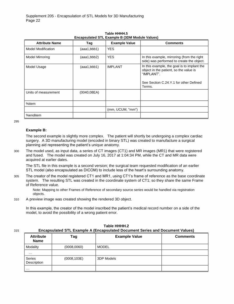
Table HHHH.5
Encapsulated STL Example B (3DM Module Values)
Attribute Name Tag Example Value Comments
Model Modification (aaa1,bbb1) YES
Model Mirroring (aaa1,bbb2) YES In this example, mirroring (from the right side) was performed to create the object.
Model Usage (aaa1,bbb1) IMPLANT In this example, the goal is to implant the object in the patient, so the value is “IMPLANT”.
See Section C.24.Y.1 for other Defined Terms.
Units of measurement (0040,08EA)
%item
(mm, UCUM, "mm")
%enditem
295
Example B:
The second example is slightly more complex. The patient will shortly be undergoing a complex cardiac surgery. A 3D manufacturing model (encoded in binary STL) was created to manufacture a surgical planning aid representing the patient’s unique anatomy.
The model used, as input data, a series of CT images (CT1) and MR images (MR1) that were registered 300
and fused. The model was created on July 16, 2017 at 1:04:34 PM, while the CT and MR data were acquired at earlier dates.
The STL file in this example is a second version; the surgical team requested modification of an earlier STL model (also encapsulated as DICOM) to include less of the heart’s surrounding anatomy.
The creator of the model registered CT1 and MR1, using CT1’s frame of reference as the base coordinate 305
system. The resulting STL was created in the coordinate system of CT1; so they share the same Frame of Reference value.
Note: Mapping to other Frames of Reference of secondary source series would be handled via registration objects.
A preview image was created showing the rendered 3D object. 310
In this example, the creator of the model inscribed the patient’s medical record number on a side of the model, to avoid the possibility of a wrong patient error.
Table HHHH.2 Encapsulated STL Example A (Encapsulated Document Series and Document Values) 315
Attribute Name
Tag Example Value Comments
Modality (0008,0060) MODEL
…
Series Description
(0008,103E) 3DP Models
…

Supplement 205 - Encapsulation of STL Models for 3D Manufacturing Page 23
Attribute Name
Tag Example Value Comments
Content Date (0008,0023) 20170716
Content Time (0008,0033) 13:00:34
Acquisition DateTime
(0008,002A) 20170716 13:00:34
Image Laterality
(0020,0062) U
Burned In Annotation
(0028,0301) YES
Recognizable Visual Features
(0028,0302) NO
Source Instance Sequence
(0042,0013) A sequence referencing CT1 source images and MR1 source images
Images from 2 studies are included because they both provided source data.
%item
>Referenced SOP Class UID
(0008,1150) 1.2.840.10008.5.1.4.1.1.2.1 Referenced object is an Enhanced CT Image Storage
>Referenced SOP Instance UID
(0008,1155) 2.999.89235.5951.35894.153
The multi-frame CT image from study CT1
%enditem
%item
>Referenced SOP Class UID
(0008,1150) 1.2.840.10008.5.1.4.1.1.4.1 Referenced object is an Enhanced MR Image Storage
>Referenced SOP Instance UID
(0008,1155) 2.999.89235.5951.35894.154 The multi-frame MR image from study MR1
%enditem
Document Title (0042,0010) Cardiac Model 2
Concept Name Code Sequence
(0040,A043)
%item
(85041-2, LN, “MR XXX 3D model”) From CID 7xx1. LOINC code for MR derived 3D model
%enditem
Predecessor Documents Sequence
(0040,A360) A sequence referencing the UID of the earlier encapsulated STL
The earlier encapsulated STL is included so that end users can understand how this model relates to
%item >Include Table C.17-3 'Hierarchical SOP Instance Reference Macro'
> Study Instance UID
(0020,000D) 2.999.1241.1515.15151.515.62
> Reference (0008,1115)

Supplement 205 - Encapsulation of STL Models for 3D Manufacturing Page 24
Attribute Name
Tag Example Value Comments
Series Sequence
%item
>> Series Instance UID
(0020,000E) 2.999.89235.5951.35894.151
>> Referenced SOP Sequence
(0008,1199)
%item
>>> Referenced SOP Class UID
(0008,1150) 1.2.840.10008.5.1.4.1.1.xxxx Encapsulated STL SOP Class
>>> Referenced SOP Instance UID
(0008,1155) 2.999.1241.1515.15151.515.68
%enditem
%enditem
%item
>>Purpose of Reference Code Sequence
(0040,A170)
%item
(abcdefg01, DCM, “Further Segmentation”)
From CID 7xx2. This model modified the earlier one to achieve more fine-grained segmentation
%enditem
%enditem
%enditem
MIME Type of Encapsulated Document
(0040,0012) application/stl
Encapsulated Document
(0042,0011) Byte stream representing the binary STL file.
Note that ASCII STL files are not supported.
Icon Image Sequence
(0088,0200) Sequence containing an image The pre-rendered preview image
Table HHHH.3
Encapsulated STL Example A (3DM Module Values)
Attribute Name Tag Example Value Comments
Model Modification (aaa1,bbb1) NO
Model Mirroring (aaa1,bbb2) NO
Model Usage (aaa1,bbb1) PLANNING
Units of measurement (0040,08EA)

Supplement 205 - Encapsulation of STL Models for 3D Manufacturing Page 25
Attribute Name Tag Example Value Comments
%item
(mm, UCUM, "mm")
%enditem
320