digital i/o module - veto.cl · conduit clamps approved for the nema 4x enclosure (or an enclosure...
TRANSCRIPT
Model WM3000-003
User’s Guide
FastFind Links
Product Overview
Pre-installation Considerations
Configuring the Digital I/O Module
Installing the Digital I/O Module
Maintaining the Digital I/O Module
Troubleshooting
Digital I/O Module
Controlled Copy

ii
OleumTech Digital I/O Module User Guide
CONTENTS
Preface ..................................................................................................................... iv
Audience .................................................................................................................... iv
Document Revision Level ........................................................................................... iv
Changes in this Revision ............................................................................................. v
Related Documents ..................................................................................................... v
Document Conventions ............................................................................................... v
Safety and Warnings ............................................................................................. v
Typographic Conventions ........................................................................................... vi
1. Product Overview ............................................................................................... 7
Digital I/O Module ........................................................................................................ 7
Network Connection and Field Applications ................................................................ 8
Base Unit (formerly WM2000-002) .............................................................................. 9
BreeZ® Configuration Software .................................................................................. 9
Features .................................................................................................................... 10
Unpacking Package Contents ................................................................................... 10
What Else You Need ................................................................................................. 11
Hardware Description ................................................................................................ 12
Front of Digital I/O Module ................................................................................... 12
Top of Digital I/O Module ..................................................................................... 14
Bottom of Digital I/O Module ................................................................................ 15
Installation and Configuration Roadmap ................................................................... 16
2. Pre-installation Considerations ...................................................................... 17
Selecting a Site ......................................................................................................... 18
Performing a Bench Test ........................................................................................... 18
Unpack All Components ...................................................................................... 18
Set Jumper JP1 ................................................................................................... 18
Power Up the Digital I/O Module ......................................................................... 18
Configure the Digital I/O Module ......................................................................... 19
Verify the Firmware Version ................................................................................ 19
3. Configuring the Digital I/O Module ................................................................. 20
Installing the BreeZ® Software .................................................................................. 21
Specifying Communication Port Settings .................................................................. 21
Creating a New Project File ....................................................................................... 24
Editing Project File Settings ...................................................................................... 26
Controlled Copy

Contents
iii
OleumTech Digital I/O Module User’s Guide
Updating Devices with the Project File ...................................................................... 28
Configuring the I/O Bus and IO Settings ................................................................... 29
Configuring I/O Channels .......................................................................................... 30
Reading Data from the Digital I/O Module ................................................................. 31
Creating Modbus Slave Registers in a Wireless Gateway ........................................ 31
Configuring Input and Count Channels ............................................................... 32
Configuring Output Channels .............................................................................. 33
Reading Modbus Slave Registers from a Base Unit ................................................. 34
4. Installing the Digital I/O Module ...................................................................... 36
Installation Overview ................................................................................................. 37
Installing the Digital I/O Module ................................................................................. 37
Providing Power ........................................................................................................ 40
Installing the Base Unit .............................................................................................. 41
Confirming Your Installation ...................................................................................... 41
5. Maintaining the Digital I/O Module .................................................................. 42
General Maintenance ................................................................................................ 43
Updating Firmware .................................................................................................... 44
6. Troubleshooting ............................................................................................... 45
Digital I/O Module Not Communicating with BreeZ® ................................................ 47
Digital I/O Module Not Communicating with the Base Unit ....................................... 47
Digital I/O Module Reports Incorrect Channel State ................................................. 47
Resetting the Digital I/O Module ................................................................................ 48
Appendix A. Specifications .................................................................................. 49
Hardware Specifications ............................................................................................ 49
Approvals and Certifications ...................................................................................... 49
Mechanical Specifications ......................................................................................... 49
Electrical Specifications ............................................................................................. 50
Operating Conditions ................................................................................................. 50
Appendix B. Glossary ........................................................................................... 51
Appendix C. Limited Warranty.............................................................................. 52
Appendix D. Compliances .................................................................................... 53
Index ....................................................................................................................... 54
Controlled Copy

iv
OleumTech Digital I/O Module User Guide
PREFACE
This User’s Guide contains all the information required to install and configure the Digital I/O Module from OleumTech.
Before using the manual, familiarize yourself with the Table of Contents on page ii.
Set up of a Digital I/O Module should not be attempted without reading Chapter 2,
Chapter 3, and Chapter 4. All first-time users should read Chapter 1. A glossary of
common terms appears in Appendix B and troubleshooting suggestions are in
Chapter 6.
Audience
This User’s Guide is intended for qualified installers and factory representatives who
install the Digital I/O Module. This document assumes that users are familiar with
using tools such as screwdrivers and wrenches to install transmitter and gateways in
the field. Users who will be performing the Modbus operations described in this
guide should also have prior knowledge of Modbus Protocol Standards.
Document Revision Level
This section provides a history of the revision changes to this document.
Revision Date Description
B 01/20/2012 Document completely rewritten
C 05/08/2013 Revised NEMA Enclosure Installation, added providing power warnings
D 03/06/2014 Added ATEX & IECEX markings; added fuse related warning; removed all references to
SCADALogic & WIO; corrected power input to 9-24 VDC.
E 12/11/2014 Updated document to resolve misleading discrepancies, replaced figured 2.1 on page 18,
updated jumper setting and Digital I/O picture. Updated Company’s address
F 01/07/2014 Updated accordingly to match revision D details that were overlooked at time of release.
G 10/15/2015 Removed WIO, updated product images
Controlled Copy
Preface
v
OleumTech Digital I/O Module User’s Guide
Changes in this Revision
Updated document to reflect intended changes specified in revision D, details were
overlooked upon release. This revision updated all discrepancies overlooked in
revision D.
Related Documents
In addition to this user’s guide, you may find the following additional documents helpful.
Wireless Gateway User’s Guide (80-7004-001)
BreeZ® Configuration Software User’s Guide (80-7023-001)
Document Conventions
This document uses the following additional conventions to draw your attention to certain
information.
Safety and Warnings
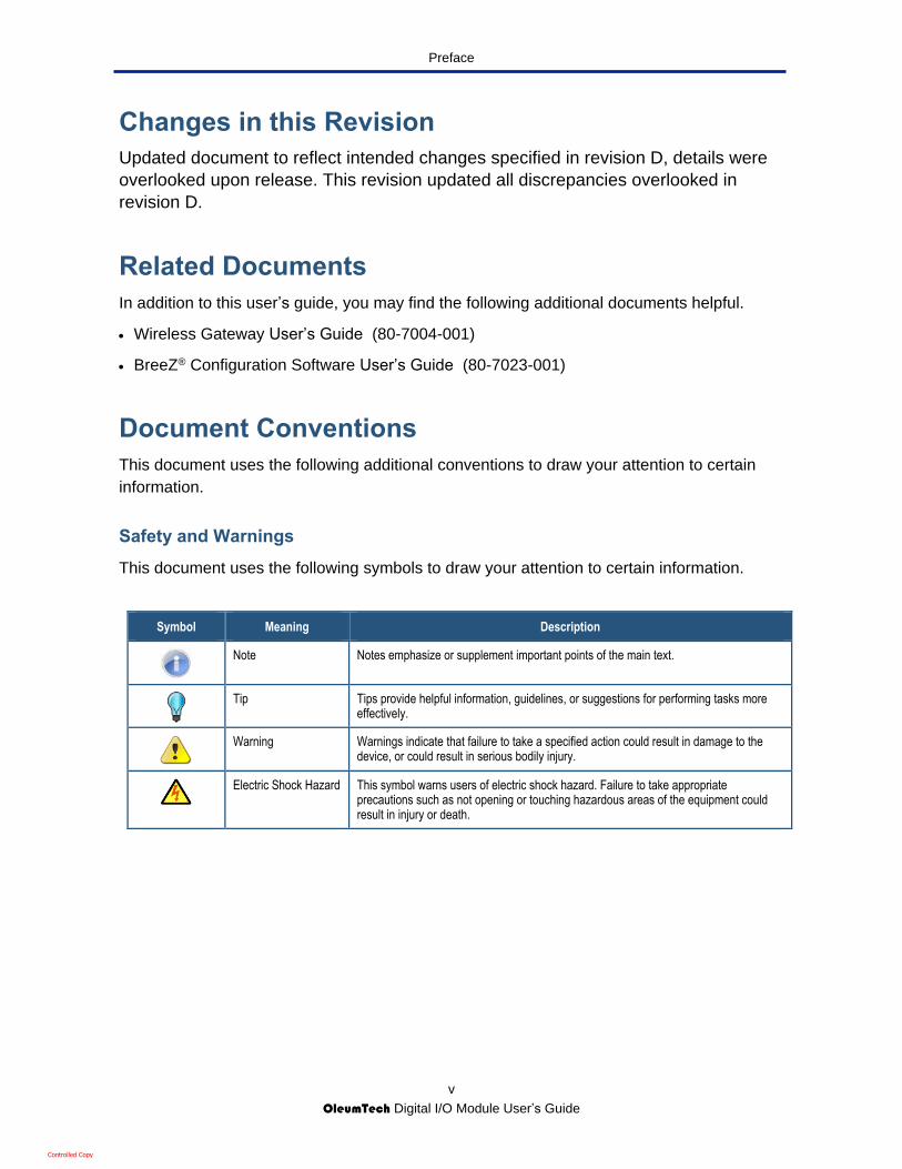
This document uses the following symbols to draw your attention to certain information.
Symbol Meaning Description
Note Notes emphasize or supplement important points of the main text.
Tip Tips provide helpful information, guidelines, or suggestions for performing tasks more effectively.
Warning Warnings indicate that failure to take a specified action could result in damage to the device, or could result in serious bodily injury.
Electric Shock Hazard This symbol warns users of electric shock hazard. Failure to take appropriate precautions such as not opening or touching hazardous areas of the equipment could result in injury or death.
Controlled Copy

Preface
vi
OleumTech Digital I/O Module User’s Guide
Typographic Conventions
This document also uses the following typographic conventions.
Convention Description
Bold Indicates text on a window, other than the window title, including menus, menu options, buttons, fields, and labels.
Italic Indicates a variable, which is a placeholder for actual text provided by the user or system. Angled brackets (< >) are also used to indicate variables.
screen/code Indicates text that is displayed on screen or entered by the user.
< > angled brackets
Indicates a variable, which is a placeholder for actual text provided by the user or system. Italic font is also used to indicate variables.
[ ] square brackets
Indicates optional values.
{ } braces Indicates required or expected values.
| vertical bar Indicates that you have a choice between two or more options or arguments.
Controlled Copy

7
OleumTech Digital I/O Module User Guide
1. PRODUCT OVERVIEW
Digital I/O Module
Thank you for choosing the Digital I/O Module from OleumTech.
The Digital I/O Module is a member of the Monitoring System, an integral assembly that
includes a Base Unit. Within this system, the Digital I/O Module provides eight channels that
can be configured as any combination of inputs or outputs for industrial automation and
process control applications.
The Digital I/O Module supports the Modbus RTU protocol over a 2-wire RS485 bus and can
interface with third-party Modbus master devices that support serial remote I/O. General-
purpose Modbus I/O modules can be easily added to data-acquisition systems for
monitoring status or control system.
The Digital I/O Module’s scalable design enables 247 expansion modules to be multi-
dropped to a single Modbus master device via RJ45 connectors, significantly reducing wiring
installation time. Modules addresses are configurable using OleumTech’s BreeZ
Configuration Software.
Figure 1-1. Digital I/O Module
Controlled Copy
Product Overview
8
OleumTech Digital I/O Module User’s Guide
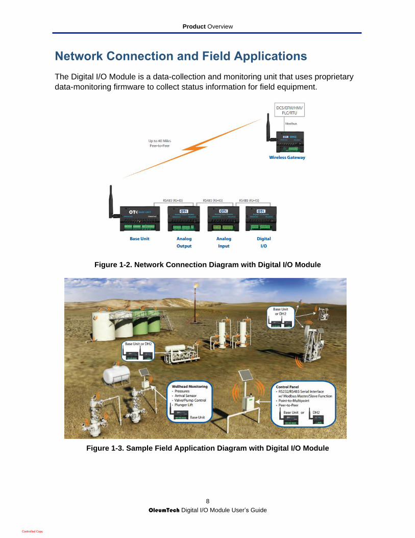
Network Connection and Field Applications
The Digital I/O Module is a data-collection and monitoring unit that uses proprietary
data-monitoring firmware to collect status information for field equipment.
Figure 1-2. Network Connection Diagram with Digital I/O Module
Figure 1-3. Sample Field Application Diagram with Digital I/O Module
Controlled Copy

Product Overview
9
OleumTech Digital I/O Module User’s Guide
Base Unit (WM2000-002)
The Base Unit is a multi-input unit that receives data from transmitters such as the
Digital I/O Module. The Base Unit accepts four analog inputs (0-5V), two discrete
inputs, and two discrete outputs for various monitoring and control applications. For
more information, refer to the Wireless Gateway User’s Guide .
Figure 1-4. Base Unit
BreeZ® Configuration Software
BreeZ® is a Microsoft Windows-based software tool for configuring OleumTech
Industrial Wireless Automation Control Modules and Transmitter family of products.
Chapter 3 describes how to use BreeZ to configure the Digital I/O Module.
Note: The procedures in Chapter 3 only cover tasks associated with the
Digital I/O Module. For information about other tasks that can be
performed using the BreeZ Configuration Software, refer to the BreeZ
Configuration Software User’s Guide.
Controlled Copy

Product Overview
10
OleumTech Digital I/O Module User’s Guide
Features
The following list summarizes the key features of the Digital I/O Module.
Expands digital I/O capabilities to Gateways (Base Unit)
Supports a mix of eight programmable (configurable) channels of digital inputs and
outputs
Configurable debounce filter (10 ms to 2000 ms)
3-to-24 VDC input for all channels
9-24 VDC (12 VDC Recommended) power input
1 A sink current for open-drain outputs
Add multiple modules to any Modbus master device via RS485 (RJ45)
Simple plug-and-play connection to Modbus master
Compact, low-profile design with low power consumption
Easy to install, configure, and use
Scalable solution
Unpacking Package Contents
Unpack your Digital I/O Module contents and confirm that no items are missing or
damaged. Your package should include:
One OleumTech Digital I/O Module
Pin connectors for attaching user wiring to the Digital I/O Module
Quick Reference Guide
If any item is missing or damaged, please contact your OleumTech representative.
Keep the carton and original packing material in case you need to store the product
or return it.
Controlled Copy

Product Overview
11
OleumTech Digital I/O Module User’s Guide
What Else You Need
To complete your Digital I/O Module Monitoring System, you need:
NEMA 4X enclosure (or an enclosure with a minimum IP 54 rating and that complies
IEC 60079-0 and IEC60079-15)
Conduit clamps approved for the NEMA 4X enclosure (or an enclosure with a
minimum IP 54 rating and that complies with IEC 60079-0 and IEC60079-15)
9-24 VDC power supply
An OleumTech Base Unit (WM2000-002)
Small flathead screwdriver and 2-inch-capable pipe
BreeZ Configuration Software (download from SUPPORT at
www.OleumTech.com)
1-foot Category 5E patch cable assembly (OleumTech P/N 65-1040-001)
Transmitter Configuration Cable (OleumTech P/N: SX1000-CC7)
A Microsoft Windows-compatible personal computer (PC) equipped with a serial or
USB port and the system requirements described under “Installing the BreeZ®
Software” on page 21
Gateway Configuration Cable (OleumTech P/N: SX1000-CC1) for PCs with a
serial port
Optional: USB-to-RS232 Adapter Cable (OleumTech P/N: SX1000-CC9) for PCs
with a USB port
Optional: An OleumTech I/O Expansion Module
Controlled Copy

Product Overview
12
OleumTech Digital I/O Module User’s Guide
Hardware Description
Front of Digital I/O Module
Figure 1-2 and Table 1-1 describe the components on the front of the Digital I/O
Module.
Figure 1-5. Front Components on the Digital I/O Module
Table 1-1. Front Components on the Digital I/O Module
Legend Description
Reset Button
Green Indicator LED
Configuration Port (under front cover) SX-1000-CC7 config cable compatible
P2 Terminal Block (Digital input / Digital output 5-8) Input power V+ Ground GND
Channel LEDs
P1 Terminal Block Digital input / Digital output 1-4
Controlled Copy

Product Overview
13
OleumTech Digital I/O Module User’s Guide
The front of the Digital I/O Module has a green indicator LED and a reset button.
The LED flashes five times when, the Digital I/O Module powers on, is being
configured, or is having its firmware updated.
The reset button reinitializes the Digital I/O Module. To reset the Digital I/O
Module, press the reset button for at least 10 seconds. The LED flashes five times
after the Digital I/O Module is reset.
Note: The reset button is recessed to prevent accidental resets. To
access It, use a paperclip or small screwdriver.
Note: When configuring the device. Update the Gateway with the project
file first. Next, remove the face plate of the DI/O Module and update the
DI/O module using the CC7 Transmitter configuration cable.
Below the LED and reset button are two terminal blocks. Facing the front of the
Digital I/O Module:
The left terminal block (P1) contains 6 pins, four for programmable inputs/outputs
1, 2, 3, and 4 and two ground pins. For a definition of these pins, see Table 1-2.
The right terminal block (P2) contains 8 pins. The six left pins are for
programmable inputs/outputs 5 through 8. The two right pins, labeled V+ and
GND, connect to the power source for the Digital I/O Module. For a definition of
these pins, see Table 1-3.
Below the terminal blocks are eight channel LEDs, one for each digital I/O channel.
These LEDs behave in the following way:
For Output Mode, the channel LED goes ON when output is ON.
For Input or Count Mode, the channel LED goes ON when a trigger occurs.
Controlled Copy
Product Overview
14
OleumTech Digital I/O Module User’s Guide
Table 1-2. Terminal Block P1 Pin Definitions
Pin Number Pin Name Description
1 PIO1 Programmable Input/Output 1
2 PIO2 Programmable Input/Output 2
3 GND Ground
4 PIO3 Programmable Input/Output 3
5 PIO4 Programmable Input/Output 4
6 GND Ground
Table 1-3. Terminal Block P2 Pin Definitions
Pin Number Pin Name Description
1 PIO5 Programmable Input/Output 5
2 PIO6 Programmable Input/Output 6
3 GND Ground
4 PIO7 Programmable Input/Output 7
5 PIO8 Programmable Input/Output 8
6 GND Ground
7 V+ Signal (6-26.4 VDC)
8 GND Ground
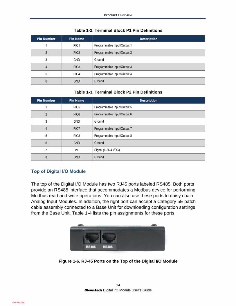
Top of Digital I/O Module
The top of the Digital I/O Module has two RJ45 ports labeled RS485. Both ports
provide an RS485 interface that accommodates a Modbus device for performing
Modbus read and write operations. You can also use these ports to daisy chain
Analog Input Modules. In addition, the right port can accept a Category 5E patch
cable assembly connected to a Base Unit for downloading configuration settings
from the Base Unit. Table 1-4 lists the pin assignments for these ports.
Figure 1-6. RJ-45 Ports on the Top of the Digital I/O Module
Controlled Copy

Product Overview
15
OleumTech Digital I/O Module User’s Guide
Table 1-4. Pin Assignments for RS485 Port on Top Panel (Digital I/O Module)
Pin Analog Receiver Generic Modbus Master Device
1 (first pin from the left)
GND GND
2 Reserved
3 TX+ TX+
4 TX− TX−
5 RX− RX−
6 RX+ RX+
7 Reserved
8 Reserved
Back of Digital I/O Module
The bottom of the Digital I/O Module has serial number, model name, power and
temperature specifications, and hazard information.
Controlled Copy
Product Overview
16
OleumTech Digital I/O Module User’s Guide
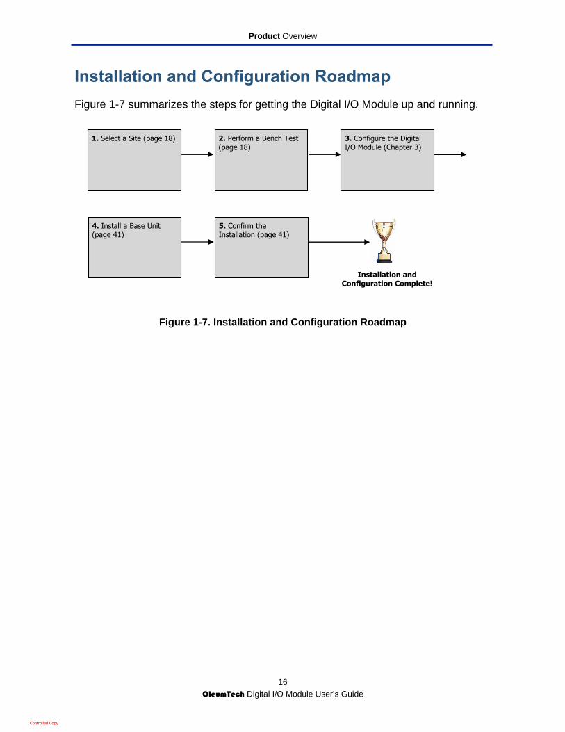
Installation and Configuration Roadmap
Figure 1-7 summarizes the steps for getting the Digital I/O Module up and running.
Figure 1-7. Installation and Configuration Roadmap
1. Select a Site (page 18) 2. Perform a Bench Test (page 18)
3. Configure the Digital I/O Module (Chapter 3)
5. Confirm the Installation (page 41)
4. Install a Base Unit (page 41)
Installation and Configuration Complete!
Controlled Copy

17
OleumTech Digital I/O Module User Guide
2. PRE-INSTALLATION CONSIDERATIONS
This chapter describes guidelines to consider before installing the Digital I/O Module.
The topics covered in this chapter are:
Selecting a Site (page 18)
Performing a Bench Test (page 18)
Controlled Copy

Pre-installation Considerations
18
OleumTech Digital I/O Module User’s Guide
Selecting a Site
When selecting a site for the Digital I/O Module, choose a location that places the
Digital I/O Module close enough to the Base Unit, so the two devices can be
connected using the 1-foot Category 5E patch cable assembly.
Performing a Bench Test
Before you install the Digital I/O Module in the field, we recommend you perform a
bench test to ensure that the unit is working properly.
Unpack All Components
Unpack all components in your Digital I/O Module package (see “Unpacking
Package Contents” on page 10).
Set Jumper JP1
If your Digital I/O Module will be daisy-chained to other Digital I/O Modules, the last
module in the chain must have jumper JP1 strapped (see Figure 2-1).
All other jumpers must be left in their default settings.
Figure 2-1. Jumper JP1 on the Digital I/O Module PCBA
Power Up the Digital I/O Module
Provide power to the Power Input (V+) and Ground (GND) pins on the Digital I/O
Module (see Figure 1-5 on page 12).
JP1
Controlled Copy

Pre-installation Considerations
19
OleumTech Digital I/O Module User’s Guide
Configure the Digital I/O Module
After powering up the Digital I/O Module, use the procedures in Chapter 3 to
configure the Digital I/O Module using the BreeZ® Configuration Software.
Verify the Firmware Version
Digital I/O Modules are sent from the factory with the latest firmware installed at the
date of shipment. Using the BreeZ software, you can verify the firmware version
installed on the Digital I/O Module and update it if necessary.
To verify the Digital I/O Module firmware version:
1. In the BreeZ Project Explorer window, double-click Module_1.
2. Press the right mouse button and click Connect. A screen similar to the following
appears, with the firmware version shown next to Version.
3. Go to the appropriate support section on the OleumTech website:
www.oleumtech.com.
4. Click the Digital I/O Module product and confirm that the firmware version shown is
the same as the one shown in the dialog box. If the version shown on the website
is higher than the one in the dialog box, upgrade the firmware (see “Updating
Firmware” on page 44).
Firmware Version
Controlled Copy

20
OleumTech Digital I/O Module User Guide
3. CONFIGURING THE DIGITAL I/O MODULE
This chapter describes how to use the BreeZ® Configuration Software to configure the Digital I/O Module.
The topics covered in this chapter are:
Installing the BreeZ® Software (page 21)
Specifying Communication Port Settings (page 21)
Creating a New Project File (page 24)
Editing Project File Settings (page 26)
Updating Devices with the Project File (page 28)
Configuring the I/O Bus and IO Settings (page 29)
Configuring I/O Channels (page 30)
Reading Data from the Digital I/O Module (page 31)
Creating Modbus Slave Registers in a Wireless Gateway (page 31)
Reading Modbus Slave Registers from a Base Unit (page 34)
Note: The procedures in this chapter only cover tasks associated with the
Digital I/O Module. For information about other tasks that can be
performed using the BreeZ software, refer to the BreeZ® Configuration
Software User’s Guide .
Controlled Copy
Configuring the Digital I/O Module
21
OleumTech Digital I/O Module User’s Guide
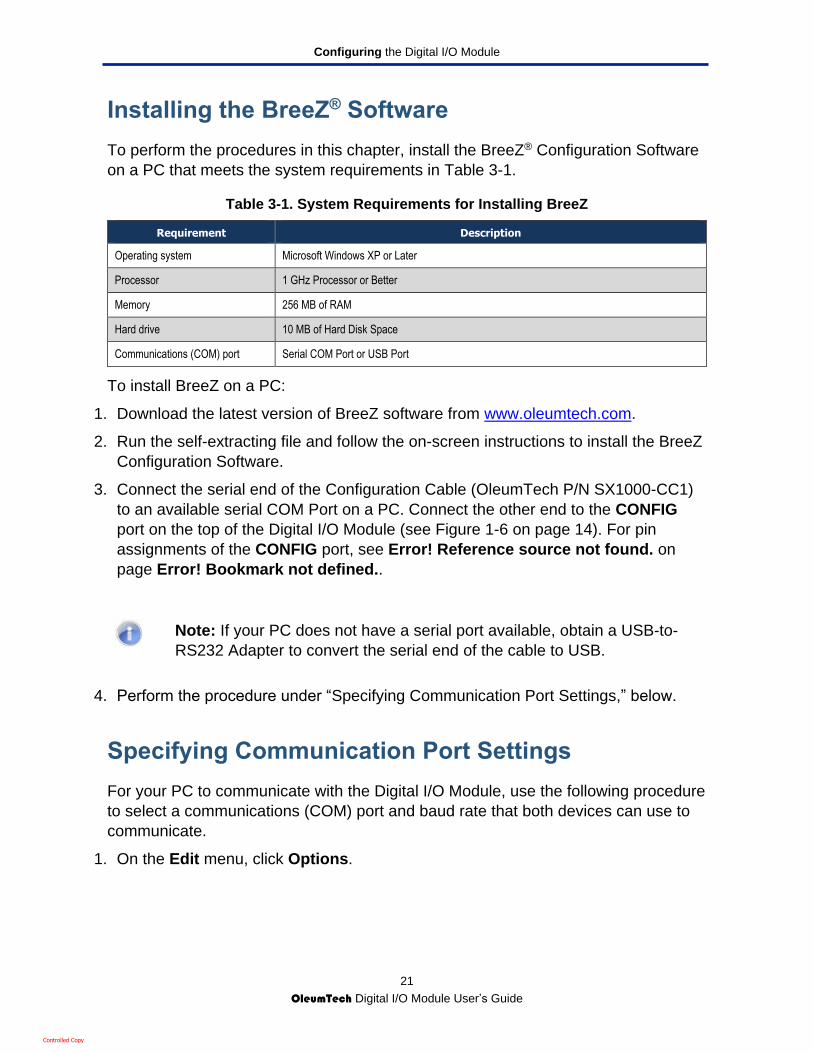
Installing the BreeZ® Software
To perform the procedures in this chapter, install the BreeZ® Configuration Software
on a PC that meets the system requirements in Table 3-1.
Table 3-1. System Requirements for Installing BreeZ
Requirement Description
Operating system Microsoft Windows XP or Later
Processor 1 GHz Processor or Better
Memory 256 MB of RAM
Hard drive 10 MB of Hard Disk Space
Communications (COM) port Serial COM Port or USB Port
To install BreeZ on a PC:
1. Download the latest version of BreeZ software from www.oleumtech.com.
2. Run the self-extracting file and follow the on-screen instructions to install the BreeZ
Configuration Software.
3. Connect the serial end of the Configuration Cable (OleumTech P/N SX1000-CC1)
to an available serial COM Port on a PC. Connect the other end to the CONFIG
port on the top of the Digital I/O Module (see Figure 1-6 on page 14). For pin
assignments of the CONFIG port, see Error! Reference source not found. on
page Error! Bookmark not defined..
Note: If your PC does not have a serial port available, obtain a USB-to-
RS232 Adapter to convert the serial end of the cable to USB.
4. Perform the procedure under “Specifying Communication Port Settings,” below.
Specifying Communication Port Settings
For your PC to communicate with the Digital I/O Module, use the following procedure
to select a communications (COM) port and baud rate that both devices can use to
communicate.
1. On the Edit menu, click Options.
Controlled Copy

Configuring the Digital I/O Module
22
OleumTech Digital I/O Module User’s Guide
The User Options screen appears.
5. Select the Port you want to use to communicate between your PC and the Digital
I/O Module.
6. Accept the following default settings or change them to suit your requirements.
– Baud Rate = 57600
– Parity = None
– Stop Bits = 1
Controlled Copy
Configuring the Digital I/O Module
23
OleumTech Digital I/O Module User’s Guide
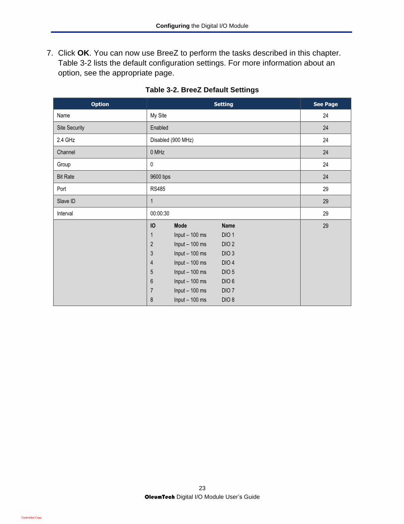
7. Click OK. You can now use BreeZ to perform the tasks described in this chapter.
Table 3-2 lists the default configuration settings. For more information about an
option, see the appropriate page.
Table 3-2. BreeZ Default Settings
Option Setting See Page
Name My Site 24
Site Security Enabled 24
2.4 GHz Disabled (900 MHz) 24
Channel 0 MHz 24
Group 0 24
Bit Rate 9600 bps 24
Port RS485 29
Slave ID 1 29
Interval 00:00:30 29
IO Mode Name
1 Input – 100 ms DIO 1
2 Input – 100 ms DIO 2
3 Input – 100 ms DIO 3
4 Input – 100 ms DIO 4
5 Input – 100 ms DIO 5
6 Input – 100 ms DIO 6
7 Input – 100 ms DIO 7
8 Input – 100 ms DIO 8
29
Controlled Copy

Configuring the Digital I/O Module
24
OleumTech Digital I/O Module User’s Guide
Creating a New Project File
A project file contains the name, network settings, and site security settings
associated with a site. After you specify the communication port settings, use the
following procedure to define a project file for use with the Digital I/O Module.
1. On the File menu, click New Project or click the New icon ( ) in the BreeZ toolbar.
The New Project dialog box appears.
2. Complete the fields in the New Project dialog box (see Table 3-3 below).
3. Click OK. A site whose name you specified in the Name field appears in the Project
Explorer window.
4. In the Project Explorer window, double-click Untitled.
5. Press the right mouse button, point to Insert, and click Base Unit. A Base Unit is
placed below the site in the Project Explorer window.
6. Double-click the newly added Base Unit in the Project Explorer window. Then press
the right mouse button, point to Insert, and click Digital I/O Module.
7. On the File menu, click Save, or click the Save icon ( ) in the BreeZ toolbar. The
Save As dialog box appears.
8. Enter a file name and click Save. The name replaces the temporary site name and
the name you entered in the New Project dialog box appears in parentheses.
9. Update the Digital I/O Module with the new project file (see “Updating Devices with
the Project File” on page 28).
Controlled Copy

Configuring the Digital I/O Module
25
OleumTech Digital I/O Module User’s Guide
Note: To read site security from a Base Unit, connect a PC with BreeZ to the
Wireless Gateway, start BreeZ, and double-click the Wireless Gateway in the
Project Explorer window. Then press the right mouse button and click Read Site
Security Key to display the key in the Output window, as shown in Figure
3-1. (The Output window shows messages and data associated with
various tasks.)
Figure 3-1. Areas of the BreeZ Screen
The following actions do not affect the security key:
Editing and saving a project file
Opening a project file previously loaded for a device
Copying or moving a project file to another location
The following actions affect the security key:
Creating a new project file and then saving
Renaming the project file
Site
Base Unit or DH2
Analog Input Module
Output Window
Worksheet
Controlled Copy
Configuring the Digital I/O Module
26
OleumTech Digital I/O Module User’s Guide
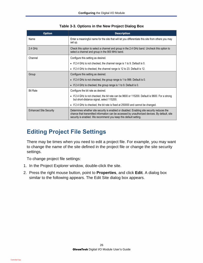
Table 3-3. Options in the New Project Dialog Box
Option Description
Name Enter a meaningful name for the site that will let you differentiate this site from others you may set up.
2.4 GHz Check this option to select a channel and group in the 2.4 GHz band. Uncheck this option to select a channel and group in the 900 MHz band.
Channel Configure this setting as desired.
If 2.4 GHz is not checked, the channel range is 1 to 9. Default is 0.
If 2.4 GHz is checked, the channel range is 12 to 23. Default is 12.
Group Configure this setting as desired.
If 2.4 GHz is not checked, the group range is 1 to 999. Default is 0.
If 2.4 GHz is checked, the group range is 1 to 9. Default is 0.
Bit Rate Configure the bit rate as desired.
If 2.4 GHz is not checked, the bit rate can be 9600 or 115200. Default is 9600. For a strong but short-distance signal, select 115200.
If 2.4 GHz is checked, the bit rate is fixed at 250000 and cannot be changed.
Enhanced Site Security Determines whether site security is enabled or disabled. Enabling site security reduces the chance that transmitted information can be accessed by unauthorized devices. By default, site security is enabled. We recommend you keep this default setting.
Editing Project File Settings
There may be times when you need to edit a project file. For example, you may want
to change the name of the site defined in the project file or change the site security
settings.
To change project file settings:
1. In the Project Explorer window, double-click the site.
2. Press the right mouse button, point to Properties, and click Edit. A dialog box
similar to the following appears. The Edit Site dialog box appears.
Controlled Copy

Configuring the Digital I/O Module
27
OleumTech Digital I/O Module User’s Guide
3. Complete the tabs in the dialog box (see Table 3-3).
4. Click OK.
5. Update the Digital I/O Module with the edited project file (see “Updating Devices
with the Project File” on page 28).
Controlled Copy
Configuring the Digital I/O Module
28
OleumTech Digital I/O Module User’s Guide
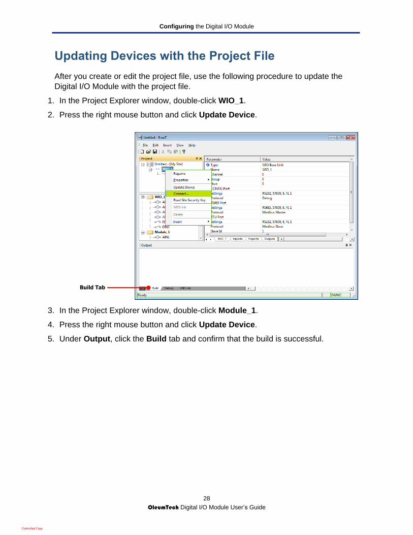
Updating Devices with the Project File
After you create or edit the project file, use the following procedure to update the
Digital I/O Module with the project file.
1. In the Project Explorer window, double-click WIO_1.
2. Press the right mouse button and click Update Device.
3. In the Project Explorer window, double-click Module_1.
4. Press the right mouse button and click Update Device.
5. Under Output, click the Build tab and confirm that the build is successful.
Build Tab
Controlled Copy

Configuring the Digital I/O Module
29
OleumTech Digital I/O Module User’s Guide
Configuring the I/O Bus and IO Settings
After you add a site, Base Unit, and Digital I/O Module, use the following procedure
to configure the I/O bus and analog input settings.
1. In the Project Explorer window, double-click Module_1.
2. Press the right mouse button, point to Properties, and click Edit. A dialog box
similar to the one in Figure 3-3 on page 30 appears, with the IO Bus tab displayed.
3. Configure the settings in the IO Bus and IO tabs.
4. After entering your configuration settings, click OK.
Table 3-4. Tabs on the Module_1 Dialog Box
Tab Option Description
IO Bus (see Figure 3-2)
Port Specifies the Base Unit port to which the Digital I/O Module is connected. Only RS485 can be used.
Slave ID Sets the slave ID of the Digital I/O Module.
IO (see Figure 3-3)
Interval Specifies how often the Digital I/O Module sends data to the Base Unit.
Range: 00:01:00 to 23:59:59
0 = configures the module for On Change mode.
1 second or longer = configures the module for Interval Time mode.
IO, Mode, Name Shows the mode and name for each digital I/O channel.
Figure 3-2. IO Bus Tab
Controlled Copy
Configuring the Digital I/O Module
30
OleumTech Digital I/O Module User’s Guide
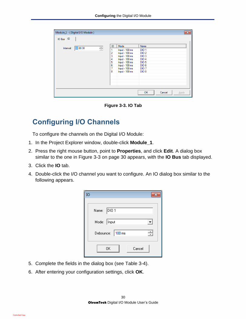
Figure 3-3. IO Tab
Configuring I/O Channels
To configure the channels on the Digital I/O Module:
1. In the Project Explorer window, double-click Module_1.
2. Press the right mouse button, point to Properties, and click Edit. A dialog box
similar to the one in Figure 3-3 on page 30 appears, with the IO Bus tab displayed.
3. Click the IO tab.
4. Double-click the I/O channel you want to configure. An IO dialog box similar to the
following appears.
5. Complete the fields in the dialog box (see Table 3-4).
6. After entering your configuration settings, click OK.
Controlled Copy
Configuring the Digital I/O Module
31
OleumTech Digital I/O Module User’s Guide
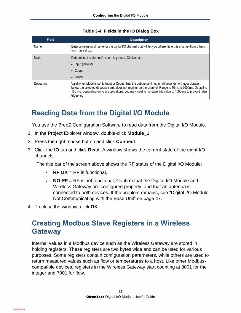
Table 3-4. Fields in the IO Dialog Box
Field Description
Name Enter a meaningful name for the digital I/O channel that will let you differentiate this channel from others you may set up.
Mode Determines the channel’s operating mode. Choices are:
Input (default)
Count
Output
Debounce Valid when Mode is set to Input or Count. Sets the debounce time, in milliseconds. A trigger duration below the selected debounce time does not register on the channel. Range is 10ms to 2000ms. Default is 100 ms. Depending on your applications, you may want to increase this value to 1000 ms to prevent false triggering.
Reading Data from the Digital I/O Module
You use the BreeZ Configuration Software to read data from the Digital I/O Module.
1. In the Project Explorer window, double-click Module_1.
2. Press the right mouse button and click Connect.
3. Click the IO tab and click Read. A window shows the current state of the eight I/O
channels.
The title bar of the screen above shows the RF status of the Digital I/O Module:
RF OK = RF is functional,
NO RF = RF is not functional, Confirm that the Digital I/O Module and
Wireless Gateway are configured properly, and that an antenna is
connected to both devices. If the problem remains, see “Digital I/O Module
Not Communicating with the Base Unit” on page 47.
4. To close the window, click OK.
Creating Modbus Slave Registers in a Wireless Gateway
Internal values in a Modbus device such as the Wireless Gateway are stored in
holding registers. These registers are two bytes wide and can be used for various
purposes. Some registers contain configuration parameters, while others are used to
return measured values such as flow or temperatures to a host. Like other Modbus-
compatible devices, registers in the Wireless Gateway start counting at 3001 for the
integer and 7001 for flow.
Controlled Copy
Configuring the Digital I/O Module
32
OleumTech Digital I/O Module User’s Guide
The procedure to use to create Modbus slave registers in the Wireless Gateway
depends on whether the channel is configured for input, count, or output in the IO
dialog box (see “Configuring I/O Channels” on page 30).
If the channel is configured for input or count, see “Configuring Input and Count
Channels,” below.
If the channel is configured for output, see “Configuring Output Channels” on page
33.
Tip: We recommend you have prior knowledge of Modbus Protocol
Standards before performing Modbus operations.
Configuring Input and Count Channels
If you used BreeZ to configure a channel as an input or count type, use the following
procedure to create Modbus slave registers.
1. In the Project Explorer window, double-click WIO_1.
2. Under the BreeZ Worksheet, click the Imports tab.
3. In the Worksheet, click the points you want to select for Modbus export.
Tip: To select rows that are next to each other, click the first row and then
hold down the Shift key and click the last row; all rows from the first to last
rows you clicked are selected. To select rows that are not next to each
other, click the first row and then hold down the Ctrl key and click each
additional row you want to select. With either method, you can deselect a
row by holding down the Ctrl key and clicking the row.
4. Press the right mouse button, point to Modbus, and click one of the following paste
options:
– Paste to Integer Table = creates integer data types.
– Paste to Float Table = creates floating-point data types.
Note: You can add a Refresh Timer to any register to verify updates at
the corresponding time interval.
Controlled Copy

Configuring the Digital I/O Module
33
OleumTech Digital I/O Module User’s Guide
5. Click the Modbus tab. Points appear as either integer or floating point or values,
depending on your selection in the previous step.
Configuring Output Channels
If you used BreeZ to configure a channel as an output type, use the following
procedure to create Modbus slave registers.
1. In the Project Explorer window, double-click WIO_1.
2. Under the BreeZ Worksheet, click the Modbus tab.
3. In the Worksheet, press the right mouse button and click New Write Import.
4. Under the BreeZ Worksheet, click the Import tab.
5. In the Worksheet, click the points you want to select for Modbus export.
Tip: To select rows that are next to each other, click the first row and then
hold down the Shift key and click the last row; all rows from the first to last
rows you clicked are selected. To select rows that are not next to each
other, click the first row and then hold down the Ctrl key and click each
additional row you want to select. With either method, you can deselect a
row by holding down the Ctrl key and clicking the row.
Controlled Copy

Configuring the Digital I/O Module
34
OleumTech Digital I/O Module User’s Guide
6. Press the right mouse button and click Copy.
7. Under the BreeZ Worksheet, click the Output tab.
8. In the Worksheet, click the Module_1 output channel. Then press the right mouse
button and click Paste Output Source.
6. On the File menu, click Save, or click the Save icon ( ) in the BreeZ toolbar to
save the Project.
Reading Modbus Slave Registers from a Base Unit
After you use the procedure in the previous section to create Modbus slave registers
in the Base Unit, verify that the Modbus slave registers can be read from the Base
Unit.
Tip: We recommend you have prior knowledge of Modbus Protocol
Standards before performing Modbus operations.
1. In the Project Explorer window, double-click WIO_1.
2. Press the right mouse button, point to Properties, and click Edit.
3. Click the RTU tab or RS485 tab and confirm that Modbus Slave is selected.
4. Open your Modbus Master device, then read register 7001 (or 3001 if set as 16 bit)
using Wireless Gateway's RTU port.
5. Under Output, click the Debug tab.
6. After the Digital I/O Module sends its data, use your Modbus Master device to read
the data from the registers.
Modbus Slave Selection
Controlled Copy

Configuring the Digital I/O Module
35
OleumTech Digital I/O Module User’s Guide
7. When Modbus registers appear in the Debug window, read function code [FC03],
data type [FP32], Register Name [R7001], and read data are shown for the Modbus
registers read.
Debug Tab
Debug Tab
Controlled Copy

36
OleumTech Digital I/O Module User Guide
4. INSTALLING THE DIGITAL I/O MODULE
This chapter describes how to install the Digital I/O Module. The topics covered in this chapter are:
Installation Overview (page 37)
Installing the Digital I/O Module (page 37)
Providing Power (page 40)
Installing the Base Unit (page 41)
Confirming Your Installation (page 41)
Before you install the Digital I/O Module, be sure you performed all bench test procedures
under “Performing a Bench Test” on page 18. In addition, observe the following warnings
and caution:
WARNING: EXPLOSION HAZARD - SUBSTITUTION OF COMPONENTS MAY
IMPAIR SUITABILITY FOR CLASS I, DIVISION 2.
WARNING: EXPLOSION HAZARD - WHEN IN HAZARDOUS LOCATIONS,
TURN OFF POWER BEFORE REPLACING OR WIRING Digital I/O Module.
WARNING: DO NOT DISCONNECT EQUIPMENT UNLESS POWER HAS
BEEN SWITCHED OFF OR THE AREA IS KNOWN TO BE NONHAZARDOUS.
CAUTION: Ensure installation of the Digital I/O Module meets applicable state
and national electrical code requirements.
Controlled Copy

Installing the Digital I/O Module
37
OleumTech Digital I/O Module User’s Guide
Installation Overview
The Digital I/O Module installation procedure consists of the following steps:
1. Installing the Digital I/O Module in a NEMA 4X-type enclosure (or an enclosure with a
minimum IP 54 rating and that complies with IEC 60079-0 and IEC60079-15). See “Installing the
Digital I/O Module.” below.
2. Providing power to the Digital I/O Module. See “Providing Power” on page 40.
3. If daisy-chaining Digital I/O Module, strap the JP1 jumper on the last module in the chain
(see “Set Jumper” on page 18).
Installing the Digital I/O Module
The following procedure describes how to install a Digital I/O Module inside a NEMA 4X-type
enclosure (or an enclosure with a minimum IP 54 rating and that complies with IEC 60079-0
and IEC60079-15). Before you perform this procedure, be sure the Digital I/O Module meets
applicable grounding requirements in the NEMA 4 enclosure.
CAUTION: Installation of the Digital I/O Module should only be installed by a
factory representative or a qualified installer.
CAUTION: The Digital I/O Module must be installed within an enclosure that
requires a tool to access. This is to prevent inadvertent disconnection of any of
the power wiring, signal wiring or communication cables.
Note: This equipment is suitable for use in Class I, Division 2 Groups A, B, C,
and D or non-hazardous locations only.
For ATEX/IECEx applications, the Base Unit or DH2 shall be installed in an
enclosure providing a degree of protection of at least IP 54 that complies with
IEC 60079-0 and IEC60079-15.
To mount the Digital I/O Module in a NEMA 4X-type enclosure (or an enclosure with a
minimum IP 54 rating and that complies with IEC 60079-0 and IEC60079-15): *Base Unit
depicted for demonstration.
1. If daisy-chaining Digital I/O Module, strap the JP1 jumper on the last module in the chain
(see “Set Jumper” on page 18).
Controlled Copy

Installing the Digital I/O Module
38
OleumTech Digital I/O Module User’s Guide
2. Remove the two screws in the Digital I/O Module top plate and carefully remove the cover
from the Module. Then loosen the two mounting screws for the DIN rail clamp.
3. Loop the connector ends through the opening in the bottom of the NEMA 4 enclosure (or
an enclosure with a minimum IP 54 rating and that complies with IEC 60079-0 and
IEC60079-15) including compression fittings, before mounting devices in the enclosure.
4. Mount each Digital I/O Module on a 32 mm (1.26 inch) DIN 1 or 35 mm (1.38 inch) DIN 3
rail inside the NEMA 4X enclosure (or an enclosure with a minimum IP 54 rating and that
complies with IEC 60079-0 and IEC60079-15). The location in the enclosure must allow
access to the connectors for easy installation and service.
Controlled Copy
Installing the Digital I/O Module
39
OleumTech Digital I/O Module User’s Guide
5. If daisy-chaining Digital I/O Modules, connect them using the RS485 port on the top of the
modules and the 1-foot Category 5E patch cable assembly. Strap jumper JP1 on the last
module in the chain (see Figure 2-1 on page 18).
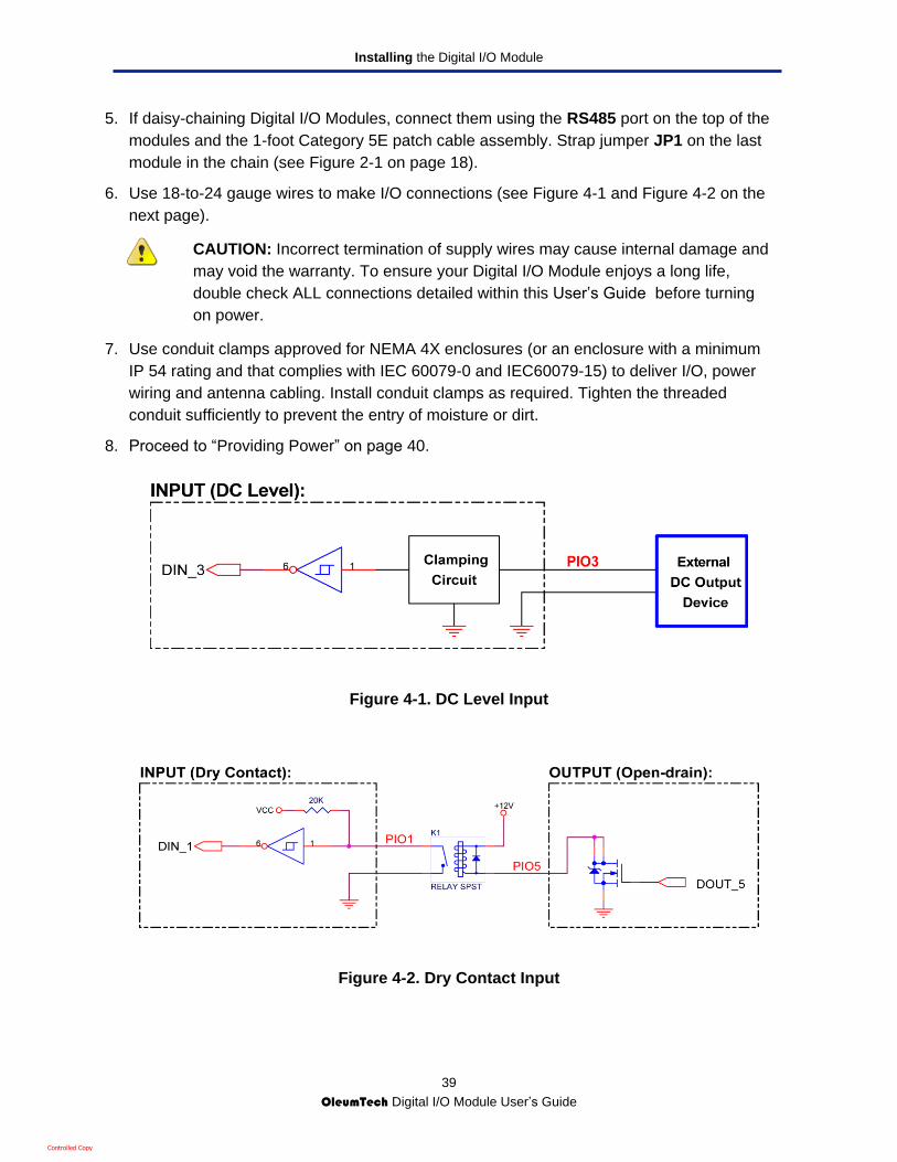
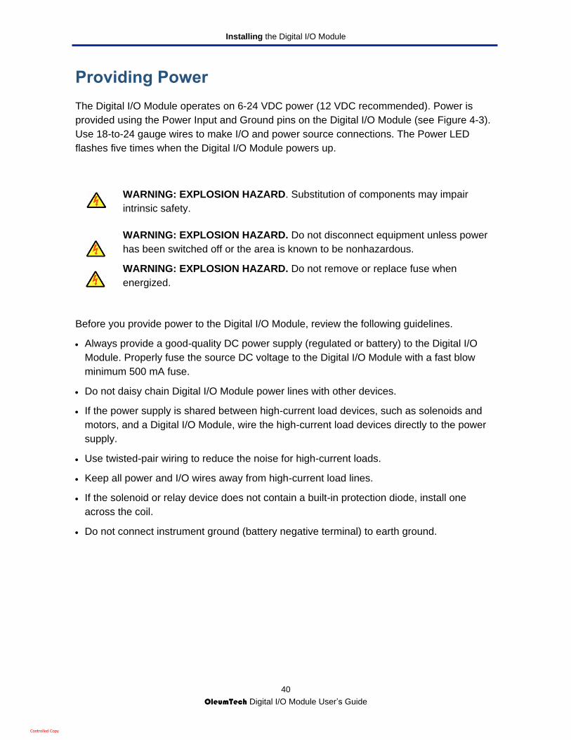
6. Use 18-to-24 gauge wires to make I/O connections (see Figure 4-1 and Figure 4-2 on the
next page).
CAUTION: Incorrect termination of supply wires may cause internal damage and
may void the warranty. To ensure your Digital I/O Module enjoys a long life,
double check ALL connections detailed within this User’s Guide before turning
on power.
7. Use conduit clamps approved for NEMA 4X enclosures (or an enclosure with a minimum
IP 54 rating and that complies with IEC 60079-0 and IEC60079-15) to deliver I/O, power
wiring and antenna cabling. Install conduit clamps as required. Tighten the threaded
conduit sufficiently to prevent the entry of moisture or dirt.
8. Proceed to “Providing Power” on page 40.
Figure 4-1. DC Level Input
Figure 4-2. Dry Contact Input
Controlled Copy
Installing the Digital I/O Module
40
OleumTech Digital I/O Module User’s Guide
Providing Power
The Digital I/O Module operates on 6-24 VDC power (12 VDC recommended). Power is
provided using the Power Input and Ground pins on the Digital I/O Module (see Figure 4-3).
Use 18-to-24 gauge wires to make I/O and power source connections. The Power LED
flashes five times when the Digital I/O Module powers up.
WARNING: EXPLOSION HAZARD. Substitution of components may impair
intrinsic safety.
WARNING: EXPLOSION HAZARD. Do not disconnect equipment unless power
has been switched off or the area is known to be nonhazardous.
WARNING: EXPLOSION HAZARD. Do not remove or replace fuse when
energized.
Before you provide power to the Digital I/O Module, review the following guidelines.
Always provide a good-quality DC power supply (regulated or battery) to the Digital I/O
Module. Properly fuse the source DC voltage to the Digital I/O Module with a fast blow
minimum 500 mA fuse.
Do not daisy chain Digital I/O Module power lines with other devices.
If the power supply is shared between high-current load devices, such as solenoids and
motors, and a Digital I/O Module, wire the high-current load devices directly to the power
supply.
Use twisted-pair wiring to reduce the noise for high-current loads.
Keep all power and I/O wires away from high-current load lines.
If the solenoid or relay device does not contain a built-in protection diode, install one
across the coil.
Do not connect instrument ground (battery negative terminal) to earth ground.
Controlled Copy

Installing the Digital I/O Module
41
OleumTech Digital I/O Module User’s Guide
Figure 4-3. Power Input and Ground Pins on the Digital I/O Module
Installing the Base Unit
To complete the Digital I/O Module installation, install one or more Base Units (refer to the
Base Unit and DH2 User’s Guide). Use the Gateway Configuration Cable to connect to the
Module’s RS485/RJ-45 port.
CAUTION: When connecting to a Base Unit, verify that the Base Unit jumper
settings are configured for full-duplex.
Confirming Your Installation
After you complete your installation, use the BreeZ® Configuration Software to create a
project file and confirm Modbus communication between the Digital I/O Module and the
Wireless Gateway (see Chapter 3).
V+ and GND Pins
Controlled Copy
42
OleumTech Digital I/O Module User Guide
5. MAINTAINING THE DIGITAL I/O MODULE
This chapter describes maintenance procedures for the Digital I/O Module.
The topics covered in this chapter are:
General Maintenance (page 43)
Updating Firmware (page 44)
Controlled Copy

Maintaining the Digital I/O Module
43
OleumTech Digital I/O Module User’s Guide
General Maintenance
The Digital I/O Module are easy to maintain and do not require periodic system checks.
They generally only need a yearly visual inspection for the following:
Is the Digital I/O Module still securely fastened to the mounting location?
Are there any visible signs of corrosion, cracks or residue build-up on the unit?
Has anything about the intended use of the original application changed?
If the Digital I/O Module is securely fastened, with no signs of corrosion, cracks, or residue
build-up, or if nothing has changed about the location of its intended use, it should continue
to operate within designed specification.
If the Digital I/O Module is not securely fastened; if there are signs of corrosion, cracks,
residue build-up; or if there has been a change to the location of its intended use resulting in
undesirable performance, contact the manufacturer for service instructions.
WARNING: TO PREVENT STATIC DISCHARGE, WIPE WITH DAMP CLOTH
ONLY.
Controlled Copy
Maintaining the Digital I/O Module
44
OleumTech Digital I/O Module User’s Guide
Updating Firmware
You update the Digital I/O Module firmware using the BreeZ® Configuration Software. The
following procedure describes how to update the Digital I/O Module firmware. It assumes
you attached a PC to the configuration port on the top of the Digital I/O Module (see Figure
1-6 on page 14) and started BreeZ (see “Specifying Communication Port Settings” on page
21).
1. Launch a browser on the PC attached to the configuration port on the front of the Digital
I/O Module.
2. Go to the appropriate support section on the OleumTech website: www.oleumtech.com.
3. Click the Digital I/O Module product.
4. Follow the on-screen instructions to download the firmware from the website to the PC.
5. In the BreeZ Project Explorer window, double-click Module_1.
6. Press the right mouse button and click Connect.
7. Click the Flash button.
8. Go to the location where you downloaded the new firmware, then double-click the firmware
file.
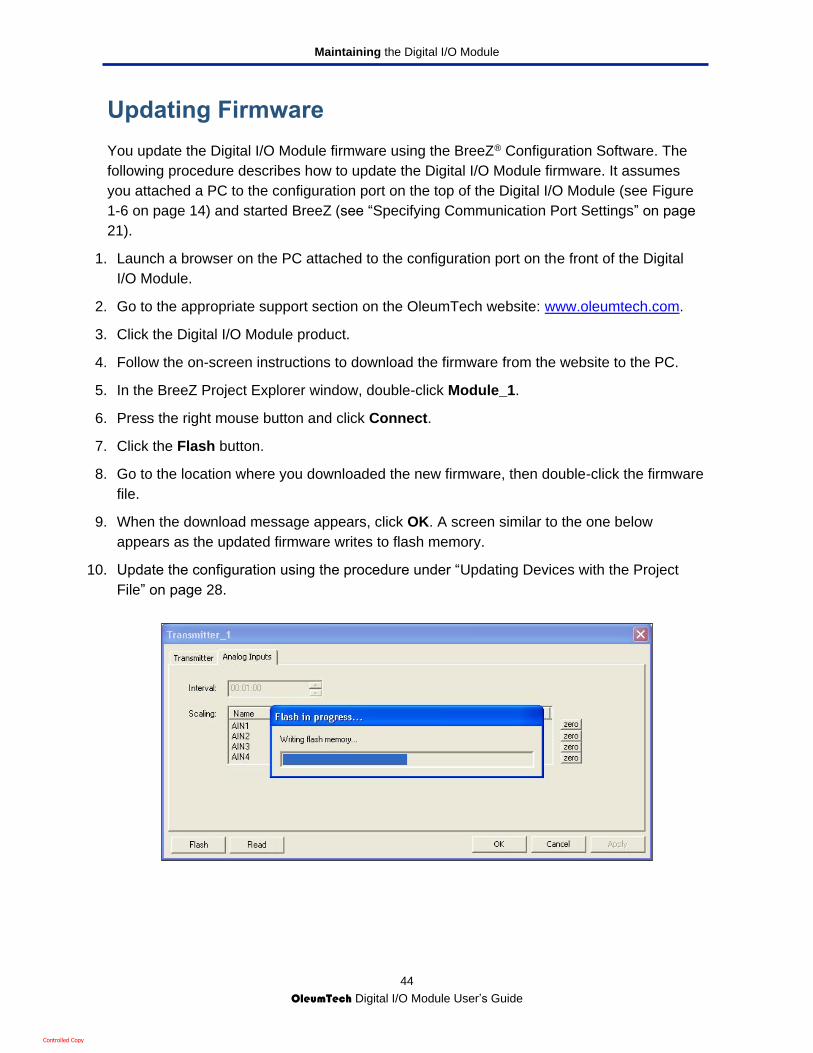
9. When the download message appears, click OK. A screen similar to the one below
appears as the updated firmware writes to flash memory.
10. Update the configuration using the procedure under “Updating Devices with the Project
File” on page 28.
Controlled Copy

45
OleumTech Digital I/O Module User Guide
6. TROUBLESHOOTING
In the unlikely event you encounter a problem using the Digital I/O Module, refer to the troubleshooting suggestions in this chapter to identify and resolve the problem.
The topics covered in this chapter are:
Digital I/O Module Not Communicating with BreeZ® (page 47)
Digital I/O Module Not Communicating with the Base Unit (page 47)
Digital I/O Module Reports Incorrect Channel State (page 47)
Controlled Copy

Troubleshooting
46
OleumTech Digital I/O Module User’s Guide
Resetting the Digital I/O Module (page 48)
Controlled Copy
Troubleshooting
47
OleumTech Digital I/O Module User’s Guide
Digital I/O Module Not Communicating with BreeZ®
If you are not able to communicate with the Digital I/O Module using the BreeZ®
Configuration Software:
1. Check that the power connection to the Digital I/O Module is secure.
2. Connect the PC running BreeZ configuration software to the Digital I/O Module.
3. Confirm that PC’s COM port and the COM port configured in the BreeZ Configuration
Software are the same (see “Specifying Communication Port Settings” on page 21). Also,
verify that the COM port is not being used by another device, as this can block
communications with the Digital I/O Module.
4. Check that the appropriate device is selected in the BreeZ Configuration Software.
Digital I/O Module Not Communicating with the Base Unit
If the Digital I/O Module is not communicating with the Base Unit, and the debug data from
the Base Unit reads “Error 3000” or “Error 6000:”
1. Update all devices with the same project file (see “Updating Devices” on page 28).
2. Check that the Category 5E patch cable assembly is securely attached at both ends.
3. Confirm that the Interval setting for the Digital I/O Module and Base Unit is correct (see
Table 3-4 on page 29).
4. Confirm that the Base Unit is configured for full-duplex communications (refer to the
Wireless Gateway User’s Guide).
Digital I/O Module Reports Incorrect Channel State
If the Digital I/O Module is reporting an incorrect state for a channel, Module’s channel may
be configured to On and its Debounce Time may be set to less than 1000 ms. Set the
Interval Time to 30 seconds (see “Configuring the I/O Bus and IO Settings” on page 29) and
the Debounce Time to 1000 ms (see “Configuring I/O Channels” on page 30).
Controlled Copy
Troubleshooting
48
OleumTech Digital I/O Module User’s Guide
Resetting the Digital I/O Module
The top of the Digital I/O Module has a reset button for reinitializing the unit.
To reset the Digital I/O Module:
1. Remove the top cover of the Digital I/O Module.
2. Find the reset button on the front of the Digital I/O Module (see Figure 1-5 on page 12).
3. Using a small screwdriver, push in and hold the recessed reset button for at least 10
seconds, then release. The LED flashes five times after the device is reset.
Controlled Copy

49
OleumTech Digital I/O Module User Guide
APPENDIX A. SPECIFICATIONS
Hardware Specifications Device Functionality: Digital Input/Output Expansion Module
I/O Interface: 8 programmable channels for digital inputs and outputs
Inputs: Dry contact – internal 20K pull-up resistor on each port
DC voltage range: 3-to-24 VDC (Max); Vil = 1.0V, Vih = 2.4 V
Current: 1 mA < (3 or 5 V), 2.7 mA (12 V), 7.2 mA (24 V)
Debounce: software configurable 10 to 2000 ms
Outputs: Open drain with 1 A sink current
Interface: Terminal block for I/O and external power input
RS485 (RJ45 2-wire), Modbus/RTU protocol
Multi-dropped Units: 247 maximum
Self-Diagnostics: Contains comprehensive self-checking software and hardware for continuous monitoring of operation
Approvals and Certifications Over Voltage Rating: Transient voltage suppressor on each port
Safety: Divisions/Zones: Class I; Division 2, Groups A, B, C, D T4
ATEX: Sira 14ATEX4143X; Ex nA IIC T4 Gc; II 3 G; 0518
IECEx: IECEx SIR 13.0055X; Ex nA IIC T4 Gc
FCC:
FCC Part 15
Industry Canada (IC): ICES-003
Mechanical Specifications Dimensions: Width: 3.8 inches (97 mm)
Height: 1.4 inches (36 mm)
Depth: 3 inches (76 mm)
Mounting Hardware: DIN rail or direct mount / custom enclosures available
Controlled Copy

Specifications
50
OleumTech Digital I/O Module User’s Guide
Electrical Specifications DC Power Input: 9-24 VDC maximum; 12 VDC normal (recommended)
Power Consumption: 360 mW @ 12 VDC (Max) (All LEDs ON)
60 mW @ 12 VDC (Max) (All LEDs OFF)
LED Indicators: Eight LEDs, indicating ON/OFF state of open-drain outputs or LOW/HIGH state of input signals
Wiring: 18- 24 AWG
Operating Conditions Temperature: Ambient Temperature (Divisions/Zones): -40 F to 176 F (-40 C to 80 C);
Ambient Temperature (ATEX / IECEx): -4 F to 176 F (-20 C to 80 C);
Humidity: 0 to 99%, non-condensing
Humidity: 0% to 95%, non-condensing
Controlled Copy

51
OleumTech Digital I/O Module User Guide
APPENDIX B. GLOSSARY
Term Definition
Baud rate A data transmission rate (bits/second) for communications devices, such as the Digital I/O Module, Digital I/O Module, and Wireless Gateway.
COM port A communications channel or pathway over which data is transferred between computing devices, such as the Digital I/O Module, Digital I/O Module, and Wireless Gateway.
Error Status of the last read operation performed by the Digital I/O Module. A status of 0 = OK. For other error status conditions, see BreeZ User’s Guide for additional error codes.
Interval A Digital I/O Module setting that specifies how often the Module sends data to the Base Unit.
Modbus A high-level serial communications protocol for industrial networks. Modbus protocol is defined as a master/slave protocol, where a device operating as a master polls one or more devices operating as a slave. A slave device cannot volunteer information; it must wait to be asked for it. The master writes data to a slave device’s registers and reads data from a slave device’s registers. A register address or register reference is always in the context of the slave’s registers.
900 MHz One of two frequency bands that the Digital I/O Module can use (the other is 2.4 GHz). This frequency is located in the Industrial, Scientific and Medical (ISM) band. The main characteristic of this bands is it is unlicensed. This means that users are free to use it without having to register or pay, apart from purchasing the radio hardware.
Serial port A serial communication physical interface that complies to the RS-232 standard for transferring data. Many modern PCs have USB ports instead of a serial port.
2.4 GHz One of two frequency bands that the Digital I/O Module can use (the other is 900 MHz). Like the 900 MHz band, this frequency is located in the ISM band and unlicensed. In the United States, FCC rules favor the 2.4 GHz over 900 MHz for a fixed point-to-point link, allowing considerable larger transmit power which translates to increased distance.
USB Universal Serial Bus. A port for connecting computing devices, such as a PC and Wireless Gateway.
Controlled Copy

52
OleumTech Digital I/O Module User Guide
APPENDIX C. LIMITED WARRANTY
a. OleumTech warrants that goods described herein and manufactured by
OleumTech are free from defects in material and workmanship for two (2)
years from the date of shipment.
b. OleumTech warrants that goods repaired by it pursuant to the warranty are free
from defects in material and workmanship for a period to the end of the original
warranty or ninety (90) days from the date of delivery of repaired goods,
whichever is longer.
c. Warranties on goods not manufactured by OleumTech are expressly limited to
the terms of the warranties given by the manufacturer of such goods.
d. All warranties are void in the event that the goods or systems or any part
thereof are (i) misused, abused or otherwise damaged, (ii) repaired, altered or
modified without OleumTech’s consent, (iii) not installed, maintained and
operated in strict compliance with instructions furnished by OleumTech, (iv)
worn, injured or damaged from abnormal or abusive use in service time, (v)
subjected to acts of God, or extreme weather phenomenon including, but not
limited to, flood, lightning, tornado or hurricane, or (vi) intentional acts including,
but not limited to vandalism, sabotage, explosion or acts of terrorism.
e. THESE WARRANTIES ARE EXPRESSLY IN LIEU OF ALL OTHER
WAARANTIES EXPRESSED OR IMPLIED (INCLUDING WITHOUT
LIMITATION WARRANTIES AS TO MERCHANTABILITY AND FITNESS FOR
A PARTICULAR PURPOSE), AND NO WARRANTIES, EXPRESSED OR
IMPLIED, NOR ANY REPRESENTATIONS, PROMISES, OR STATEMENTS
HAVE BEEN MADE BY OLEUMTECH UNLESS ENDORSED HEREIN IN
WRITING. FURTHER, THERE ARE NO WARRANTIES, WHICH EXTEND
BEYOND THE DESCRIPTION OF THE FACE HEREOF. ANY WARRANTIES
BEYOND THOSE SET FORTH HEREIN MUST COME DIRECTLY FROM
OLEUMTECH.
Controlled Copy

53
OleumTech Digital I/O Module User Guide
APPENDIX D. COMPLIANCES
Important Information to the User
This device MUST be professionally installed only by a factory representative or a
trained authorized technician.
Changes or modifications not expressly approved by the manufacturer may void the
user’s authority to operate the equipment.
This device complies with Part 15 of the FCC Rules. Operation is subject to the
following two conditions: 1) this device may not cause harmful interference, and 2) this
device must accept any interference received, including interference that may cause
undesired operation.
FCC Interference Statement
This equipment has been tested and found to comply with the limits for a class B digital
device, pursuant to Part 15 of the FCC Rules. These limits are designed to provide
reasonable protection against harmful interference in a residential installation. This
equipment generates, uses and can radiate radio frequency energy and if not installed
and used in accordance with the instructions, may cause harmful communications to
radio communications. However, there is no guarantee that interference will not occur in
a particular installation. If this equipment does cause harmful interference to radio or
television reception, which can be determined by turning the equipment off and on, the
user is encouraged to try to correct the interference by one of the following measures:
Reorient or relocate the antenna.
Increase the separation between the equipment and receiver.
Consult the manufacturer for technical help.
This equipment has been certified to comply with the limits for a class B computing device,
pursuant to FCC Rules. In order to maintain compliance with FCC regulations, shielded
cables must be used with this equipment. Operation with non-approved equipment or use of
unshielded cables is likely to result in interference to radio and television reception. The user
is cautioned that changes or modifications made to the equipment without the approval of
the manufacturer could void the user’s authority to operate this equipment.
Controlled Copy

54
OleumTech Digital I/O Module User Guide
INDEX
A
Approvals, 48
B
Base Unit, 9
not communicating with Digital I/O Module, 46
providing power, 40
Bench test, 18
BreeZ configuration software, 9
COM port, 21
creating a project file, 24
creating Modbus slave registers, 31
editing a project file, 26
I/O bus and IO settings, 29
installing, 21
not communicating with Digital I/O Module, 46
reading data, 31
reading Modbus slave registers, 34
site security, 24
updating devices, 28
C
Certifications, 48
Channel LEDs, 13
COM port selection, 21
Compliances, 52
Configuration roadmap, 16
Confirming installation, 41
Contents of package, 10
Conventions in this document, v
Creating
Modbus slave registers, 31
new project file, 24
D
Data read from Digital I/O Module, 31
Devices, updating, 28
Digital I/O Module
configuration, 20
features, 10
field applications, 8
general maintenance, 43
incorrect channel state, 47
installation, 37
installation and configuration roadmap, 16
jumpers, 18
limited warranty, 51
NEMA enclosure, 38
network connection, 8
not communicating with Base Unit, 46
not communicating with BreeZ software, 46
package contents, 10
pre-installation, 17
reading data from, 31
resetting, 47
site selection, 18
specifications, 48
troubleshooting, 45
Document conventions, v
E
Editing project file, 26
Electriccal specifications, 49
F
FCC interference statement, 52
Features, 10
Field applications, 8
Firmware
updating, 44
verifying, 19
G
General maintenance, 43
Controlled Copy

Index
55
OleumTech Digital I/O Module User’s Guide
Glossary, 50
H
Hardware
description, 12
specifications, 48
I
I/O bus settings, 29
Installation
BreeZ configuration software, 21
confirming, 41
overview, 38
providing power, 40
roadmap, 16
Base Unit, 41
Installing the Digital I/O Module, 38
IO settings, 29
J
Jumpers, 18
L
Limited warranty, 51
M
Mechanical specifications, 48
Modbus slave registers
creating, 31
reading, 34
N
Network connection, 8
O
Operating conditions, 49
P
Package contents, 10
Project file
creating, 24
editing, 26
R
Reading
data, 31
Modbus slave registers, 34
Related documents, v
Resetting the Digital I/O Module, 47
Roadmap, 16
S
Security, 24
Selecting a site, 18
Setting site security, 24, 26
Site
security, 24
selection, 18
Specifications
approvals, 48
certifications, 48
electrical, 49
hardware, 48
mechanical, 48
operating conditions, 49
T
Troubleshooting
Digital I/O Module not communicating with Base
Unit, 46
Digital I/O Module not communicating with
BreeZ, 46
incorrect channel state, 47
U
Updating
devices, 28
firmware, 44
W
What else you need, 11
Base Unit
installation, 41
overview, 9
Controlled Copy

56
OleumTech Digital I/O Module User Guide
Controlled Copy
OleumTech Corporation
19762 Pauling Foothill Ranch, CA. 92610
Phone: 866.508.8586 949.305.9009 Fax: 949.305.9010
www.oleumtech.com
OleumTech has made a good faith effort to ensure the accuracy of the information in this document and disclaims the implied warranties of merchantability and fitness for a particular purpose and makes no express warranties, except as may be stated in its written agreement with and for its customers.
OleumTech shall not be held liable to anyone for any indirect, special or consequential damages due to omissions or errors. The information and specifications in this document are subject to change without notice.
Copyright © 2015. All Rights Reserved. BreeZ is a registered trademark and OleumTech is a trademark of OleumTech Corporation. Other trademarks and registered trademarks are the property of their respective owners.
OleumTech Digital I/O Module User’s Guide
October 15, 2015
Document number: 80-7015-001_G
Controlled Copy