digital modulations using the universal software radio
TRANSCRIPT

Digital Modulations Using the Universal Software Radio
Peripheral
By
Daniel Keith Artis
Senior Project
ELECTRICAL ENGINEERING DEPARTMENT
California Polytechnic State University
San Luis Obispo
2011
Table of Contents
Acknowledgements ........................................................................................................ i
I. Introduction ..........................................................................................1
I. Background ..........................................................................................2
II. Requirements .......................................................................................4
III. Design ...............................................................................................9
A. Introduction to Software Design ....................................................11
1. BASK ...................................................................................................................... 12
2. BFSK ...................................................................................................................... 14
B. USRP ..............................................................................................16
IV. Test Plan .........................................................................................18
V. Test Results ....................................................................................20
VI. Conclusion and Recommendations ................................................24
VII. Bibliography ...................................................................................26
VIII. Appendices .....................................................................................28
A. Program Listing..............................................................................28
B. Parts List .........................................................................................28
C. BASK_gui.py .................................................................................28
D. BFSK_gui.py..................................................................................29
E. BASK Using USRP ........................................................................31
F. BFSK Using USRP ........................................................................33
G. Quick Start Installation Guide ........................................................35
H. Signal Transmission Lab ................................................................43

List of Tables
Table I: Modulation Type And Price Differences Of SDRs ..........................................7
Table II: Frequency And Software Differences Of SDRs .............................................8
List of Figures
Figure 1: System Block Diagram ................................................................................10 Figure 2: USRP Block Diagram[7] ..............................................................................11
Figure 3: BASK Block Diagram ..................................................................................13 Figure 4: BFSK Block Diagram ..................................................................................15 Figure 5: USRP Connections .......................................................................................17 Figure 6: BASK Modulation .......................................................................................21
Figure 7: BFSK Modulation ........................................................................................21 Figure 8: BFSK Waveform Before Transmission .......................................................22 Figure 9: BFSK After Reception By the USRP ...........................................................23
Figure 10: gcc-g++ Location .......................................................................................36 Figure 11: The WxPython Window .............................................................................39 Figure 12: The Cygwin Window After demo.py File Is Run ......................................40
Figure 13: Cygwin After GNU Radio Installation ......................................................42
List of Equations
Equation 1: Message Signal………………………………………………………….14
Equation 2: BASK Carrier Frequency……………………………………………….14
Equation 3: BASK Modulated Signal……………………………………………….14
Equation 4: BFSK First Carrier Frequency………………………………………….15
Equation 5: BFSK Second Carrier Frequency……………………………………….15
Equation 6: BFSK Modulated Signal………………………………………………..15
i
Acknowledgements
I would like to thank Professor Oliver for giving me the opportunity to work
on this project and allowing me to work on something I was truly passionate about.
Also, I would like to thank my parents Alvin and Cynthia Artis for always supporting
my dreams and goals.

Abstract
Software defined radios (SDRs) are versatile systems that integrate hardware
and software to create a reprogrammable wireless system. Due to the versatility and
hardware requirements of a SDR, they are typically expensive and not always
affordable for educational institutions. GNU Radio is a free software package that
allows users to do signal processing on any computer using python and C++. Using
the Universal Software Radio Peripheral (USRP) board in conjunction with a
standard personal computer (PC), a RF daughterboard, and the GNU Radio software,
we can create a software defined radio that can transmit, receive, and process signals.
Because the USRP a personal computer to perform symbol generation, less
specialized hardware is needed for the implementation of a software radio, thus
reducing the overall system cost. The low cost of a USRP-based SDR enables the
implementation of SDRs in laboratory courses, allowing students to learn about
digital signal processing along with wireless communication systems.
The objective of this senior project is to develop a low-cost SDR that can be
used to support student learning of digital wireless communications in a laboratory
setting. To demonstrate the capabilities of the SDR, example modulations using
BFSK and BASK were developed. In addition, supporting documents like a “quick-
start guide” were created to assist in the implementation of SDRs in a digital
communications lab. The RFX400 daughterboard was used as a front end with the

USRP to test if a college level student could use this hardware with GNU Radio to
transmit a modulated signal. The carrier frequencies of these modulated signals were
increased to within the bandwidth of the RFX400, 400 to 500 MHz, then these signals
were transmitted and successfully received but not with the same clarity as the signal
before transmission. Transmitting signals through the air always causes signal
degradation, but the number of samples that the USRP uses during reception also
affects the quality of the received signal. The USRP and GNU Radio are the ideal
hardware and software combination to use by students due to the affordability,
versatility, and ease of use.

1
I. Introduction
Many communications systems are designed to operate at a particular
frequency, transmit gain, receive gain, and transmission range with a specific signal
modulation. The USRP with GNU Radio software allows a user to modulate a signal
using various modulation schemes, adjust the frequency within a certain range, and
process various signals without having to change hardware. The USRP uses multiple
RF front end boards that have various frequency ranges, so a specific front end board
is needed to transmit or receive a signal in a certain range.
This project was done to provide the ground work for future students interested
in learning about communication systems and signal processing though the use of a
software defined radio. To accomplish this, the hardware and software had to be low
cost, allow for programmable modulations, and be well documented so students could
learn the system with little outside assistance. A guide had to be written to show
students how to install any necessary software and connect any hardware.
Additionally, a lab was written to show students how to get started creating their own
modulations.

2
I. Background
A software defined radio (SDR) is a reconfigurable system that utilizes
hardware and software for wireless communications [1]. The reconfiguration is done
through software so that the hardware does not have to be changed with the frequency
or gain. Typically, the hardware is based upon field programmable gate arrays
(FPGAs) and is used to down convert received signals to something the hardware can
process and up convert transmitted signals to the proper frequency and bandwidth.
Digital to analog converters are used to convert digitally processed information into
an analog signal for transmission and analog to digital converters are used to convert
received analog signals to digital information that a computer understands. Because
the modulation scheme of the radio is defined in software, SDRs are ideal when
versatility is needed.
The overall goal of this project is to find a SDR that can be used in an
academic lab to teach students about digital signal processing and wireless
communication systems. An installation guide and lab need to be written to show
future users what needs to be done to start using the hardware and how to transmit
their own modulated signals respectively.
There are a few options to choose from when deciding on a software defined
radio system. Requirements of this project include: a total system cost of less than
$500, have the ability to control the modulation scheme in software, have ample

3
example code, have documentation explaining how to get started with creating
modulations, and it has to still be supported by the design company.

4
II. Requirements
The purpose of the project was to provide the ground work for a possible
future digital communications course. Hardware and software had to be chosen based
on the following:
Ease of use
Cost
Ability to create any modulation through code.
The candidates to use as a software defined radio were the Wireless Open-
Access Research Platform Radio board, the Universal Software Radio Peripheral, the
PulseBlaster direct digital synthesis board, RadioProcessor board, and the PMG-M-
130 direct digital synthesis board. Each board had their advantages for use as a SDR
for an academic project.
The, Wireless Open-Access Research Platform, WARP Radio board was a
programmable dual band RF transceiver designed at Rice University and distributed
by Mango Communications. It was able to transmit in the 2.4 to 2.5 GHz and 4.9 to
5.875 GHz range with up to a 40 MHz bandwidth. The transceiver chip on the board
could handle multiple inputs and outputs. Standard 50Ω female SMA antenna
connecters were used, which were the same as in Cal Poly’s RF classes so cables and
antennas were readily available. The Radio board required the WARP FPGA Board,
which used the Virtex-4 FPGA made by Xilinx, and the WARP Clock Board to
transmit and receive signals. The Xilinx EDK and ISE were required to program the

5
FPGA. The ISE was used in CPE 169 and 269 at Cal Poly. The EDK was used in
CPE 329 and students who have taken these classes are most likely to use a software
defined radio in the future. Both of these software packages must be purchased from
Xilinx or they can be obtained with a 30 day trial. Ideally, the full capabilities of the
software would be needed, so the cost of the software was added onto the cost of the
system. The EDK allows the hardware to be setup using VHDL and C code
implements that hardware to create a wireless system. There were labs online that
showed how to use the software to create projects along with building simple
transmitters. Examples would be needed when teaching new users, so this was a
desired feature. The academic price of the Radio, FPGA, and clock boards was
$6,500 [2].
The Universal Software Radio Peripheral, or USRP, was a motherboard made
by Ettus Research that handled the up and down conversions of transmitted and
received signals from attached daughterboards. Ettus made a variety to transceiver
daughterboards that allowed a user to transmit, receive, and process signals in
different frequency ranges. Professor Oliver had the RFX400 transceiver board that
transmitted and received signals in the 400-500 MHz range from a previous senior
project, so only the USRP would be needed to start transmitting and receiving signals.
This made the cost of the system decrease. The USRP needed a computer with the
GNU Radio software installed, so the computer could process sent and received
signals using C++ and python. Neither of these languages were taught in Cal Poly
programming classes, but there was a GNU Radio wiki online and a mailing list

6
where users can ask the USRP’s designer and other users questions. GNU Radio is a
free software package that can be installed on any Linux, Windows, or Mac OS X
computer. The versatility and cost of the software was a desired feature of this
system. The USRP1 cost was $700 [3].
The PulseBlaster DDS board, designed by SpinCore Technologies, was a
radio frequency pulse generator that was able to create digital and analog output
signals to two RF output channels. This board was only able to act as a transmitter,
sending signals in a 5 kHz to 100 MHz range. A transceiver board was most desired
for this project, so additional hardware would be needed to receive signals.
Waveforms are generated using C code and examples of modulations are provided on
the SpinCore website. The software that was used to interface and program the board
was free and provided on the SpinCore website. The example software was easy to
understand and clearly explained; additionally, the software being free was also a
desired feature. The PulseBlaster DDS was $2,495 [4].
The RadioProcessor board, designed by SpinCore Technologies, was a
transceiver board on a single PCI or USB card. This board being a transceiver was a
desired feature. The board contained a transmit port and receive port that were each
able to handle signals from 0 to 100 MHz. The same software used for the
PulseBlaster was also used for this board. The RadioProcessor board cost $6,995 [5].
The PMG-M-130 DDS board was designed by BASIL Networks to provide
users with a PCI card that could create user configurable modulations. This board
would have to be used with a desktop, so it was not a portable system. A SDR that

7
used USB was most desired. The frequencies and phases of the transmitted and
received signals could be adjusted using the graphical user interface that came with
the board’s software. Sent and received signals could only be modulated using
specific schemes that the software provided, the user could not implement code to
control the modulation. This feature was not desired because users need to be able to
create their own modulation schemes. These boards were not sold in single quantities
and a minimum order of $100,000 was required [6]
Comparisons of each SDR can be seen in Tables I and II.
Table I: Modulation Type And Price Differences Of SDRs
Board Manufacturer
Modulation
Type
Out of the
Box demo Availability Price
WARP Radio
Board
Mango
Communications Programmable Online labs available $6,500
USRP1 Ettus Research Programmable
Source code
provided available $700
RadioProcessor
board SpinCore Programmable
C code
demos available $6,995
PulseBlasterDDS SpinCore Programmable
C code
demos available $2,495
PMG-M-130
DDS
BASIL
Networks Configurable
Minimum
order
needed
min
$100,000
order

8
Table II: Frequency And Software Differences Of SDRs
Board Frequency range (MHz) Software Notes
WARP Radio Board 2400-2500, 4900-5875 Xilinx ISE, EDK
the radio board and FPGA board are included in the cost
USRP1 depends on daughterboard GNU Radio
RadioProcessor board 0-100
SpinAPI Package
A complete communication system on the board, can program modulation in C
PulseBlasterDDS 0.005-100 SpinAPI Package
Just the Tx of the system, still need Rx
PMG-M-130 DDS 0-130 PMG-M-1300 Software
PCI Interface, don't sell one board at a time
The USRP was chosen since the developers were easy to get in contact with, it
had cheapest price, and the wiki for the software was well documented. The RFX400
was already available, further reducing the cost. The hardware, USRP and RFX400,
and software, GNU Radio, had to be understood and the process for using them
together had to be documented so that a new student will be able to quickly start
using the software to send their own signals. The list of materials needed for this
project is shown in Appendices section B. A quick start installation guide had to be
written so students could install and use the GNU Radio software on their computers
without any issues. This guide is included in the Appendices section G. Additionally,
a lab report had to be written to show students how to use the software to send signals
with their own modulation schemes, which is in the Appendices section H.

9
III. Design
Various components were used in the USRP to be able to function as a
software defined radio. The USRP1 used the Altera Cyclone EP1C12Q240C8 FPGA,
which used Verilog as its HDL and was synthesized with Altera’s Quartus II web
tool. Python was used as an upper level programming language to interface with the
FPGA. When python programs were run, .rbf files were loaded onto the FPGA from
/usr/local/share/usrp/rev. The default file was std_2rxhb_2tx.rbf and was not
generated each time a python file was run, but the USRP1’s host library loaded the
.rbf file into the FPGA, so the user did not have to. The FPGA was used to do
general high-speed operations like digital up and down conversions, decimation, and
interpolation [7].
A CPU connected to the USRP1 through a USB2 port was used to process
waveforms, so a user’s computer could have been used to test modulations without
the USRP. The reason for using the FPGA was the need for versatile conversions that
were made to incoming signals and to reduce the data rates to something transferable
using USB2.0. Underneath the python code, C++ was used to do all performance
critical signal processing while python was used as a simple interface to put signal
blocks together (Padalino). The signal processing blocks that were implemented in
python were C++ classes that the GNU Radio software used. The GNU Radio
software took the outputs from the received signals that the FPGA down converted

10
and they were processed on the user’s computer using Python and C++ code. The
C++ code was compiled on the CPU of the user’s computer. The higher level Python
code did not directly affect the FPGA or USRP, only what was transmitted or
received [7]. The connections between the computer, USRP, and RFX400 can be
seen in Figure 1.
Figure 1: System Block Diagram
The USRP’s motherboard had two transmit slots and two receive slots. Each
transmit slot was connected to two high speed digital-to-analog converters and each
receive slot was connected to two high speed analog-to-digital converters. The board
used for this project was the RFX400, a radio frequency transceiver board that had a
frequency range of 400-500 MHz [3]. This board was connected to a transmit port
and a receive port, so signals could be sent and received simultaneously. A block
diagram of the USRP is shown in Figure 2.

11
Figure 2: USRP Block Diagram[7]
GNU Radio was free software package that allowed signals to be processed on
a computer. It ran on a computer independent of any RF hardware, but was set up to
interface with the USRP.
A. Introduction to Software Design
Signal modulation involves a message and a carrier signal. The message
contains data that a user wants to transmit. This message is embedded within the
carrier, which is what propagates through a channel, such as air [9]. A carrier is
needed for most transmission applications. Antenna lengths are determined by the
wavelength of their received signals. Since higher frequency signals have shorter
wavelengths, antennas designed to receive signals with shorter wavelengths are

12
smaller than those designed to receive longer wavelengths. Smaller antennas are
cheaper to produce and require less space. Due to bandwidth limitations of a channel,
a signal cannot just propagate through any medium so a carrier is needed to put the
message into a channel’s bandwidth [10]. For example, compact discs typically have
a sampling rate of 44.1 kHz, but the RFX400 cannot receive this frequency so CD
audio would have to be modulated with a carrier in the 400-500 MHz range [9].
Typically, the carrier is a higher frequency than the message. Modulation occurs
when the frequency, amplitude, or phase of a carrier is adjusted in proportion to the
message signal.
To generate a modulated signal Python code is used to design a system using
C++ classes provided in the GNU Radio software. A complete file must contain a
source and sink which are directly or indirectly connected to each other. A source
can be a signal source such as a sine or cosine wave [11]. The source must be
sampled at greater than twice the frequency of the transmitted frequency, so that the
source signal can be recovered at the receiver. Sinks are the destination of a source
signal [12]. In the ask_gui.py file, an oscilloscope sink was used to display the source
signal prior to being sent to the USRP.
1. BASK
The first digital modulation scheme implemented was binary amplitude shift
keying, or BASK. It was chosen since it had been taught in lower level Electrical
Engineering courses and could be verified by students. Two float signal sources were
created at the beginning of the file; one was a 100 Hz square wave message signal
Comment [DKA1]: Sink explanation
13
which represented binary 1s and 0s. Signal sources could be integers, floats, shorts,
or complex numbers [13]. Floats offered more precision than integers or shorts and
used fewer resources than complex numbers.
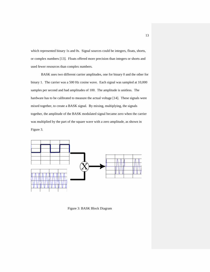
BASK uses two different carrier amplitudes, one for binary 0 and the other for
binary 1. The carrier was a 500 Hz cosine wave. Each signal was sampled at 10,000
samples per second and had amplitudes of 100. The amplitude is unitless. The
hardware has to be calibrated to measure the actual voltage [14]. These signals were
mixed together, to create a BASK signal. By mixing, multiplying, the signals
together, the amplitude of the BASK modulated signal became zero when the carrier
was multiplied by the part of the square wave with a zero amplitude, as shown in
Figure 3.
Figure 3: BASK Block Diagram

14
The BASK modulated signal is the carrier signal when the message is 1 and
no signal when the massage is 0. This signal is represented by the following equation
[15]:
m(t) = message signal, square wave (1)
ωc = 2π(500) rad/s (2)
YASK(t) = m(t)cos(ωct) (3)
The final BASK modulated signal was sent to a scope sink, which displayed the input
to the sink in an oscilloscope window. The code for this modulation can be found in
the Appendices section C.
2. BFSK
The BASK design was used to create the binary frequency shift keying
design. This modulation was chosen since it could be created using the already
implemented BASK scheme and could be verified by students. Another carrier, a 250
Hz cosine wave sampled at 10,000 samples per second with an amplitude of 100, was
added to the BASK design. This carrier was used for the frequency change required
when the message switched from 0 to 1 or 1 to 0. The message signal inverted and
offset by its amplitude, producing a 180° phase shift. To maintain the phase shift, the
original message was sent through two buffers to account for the delay that the
inversion and offset produced. This created two message signals, the original
message and a 180° phase shifted message. The 500 Hz carrier was mixed with the
original message and the 250 Hz carrier was mixed with the 180° phase shifted
message. When one mixer did not output a signal, the other mixer did. The two

15
outputs of these mixers were input into an adder to create an FSK modulated signal,
as shown in Figure 4.
Figure 4: BFSK Block Diagram
The signal is represented by the following equation [15]:
m(t) = message signal, square wave (1)
ωc1 = 2π(500) rad/s (4) ωc2 = 2π(250) rad/s (5)
YFSK(t) = m(t)cos(ωc1t) + [1-m(t)]cos(ωc2t) (6)
The final BFSK modulated signal was sent to a scope sink, which displayed the input
to the sink in an oscilloscope window. The code for this modulation can be found in
the Appendices section D.

16
B. USRP
To have the modulated signals transmitted from the USRP a few additions had to
be made to the BASK and BFSK modulation code. Instead of the scope sink, a
complex USRP sink was used. To make the source match the sink, a complex source
could have been implemented but to prevent the amount of resources from increasing
the input into the USRP sink was converted from float to complex.
The instantiated USRP sink was used to prepare the USRP for transmission.
A call to a pick transmission sub-device method was made to return the RFX400’s
specifications to a variable. The code was set up to automatically find any board
connected to any transmit slot, so the code did not have to be changed if the RFX400
was connected to the other transmission slot. A register on the USRP controls the
transmit path of a signal using a mux. The register value had to be determined based
on the previously returned RFX400 specifications using a USRP method. This
returned value was the input to a USRP sink set mux method. After the mux was set,
an object reference to the RFX400 was returned and stored in a variable using a
selected sub-devices method, which used the USRP object and RFX400
specifications. The RFX400’s gain was set to the maximum value so attenuation
would not degrade the signal since the receive and transmit antennas were always
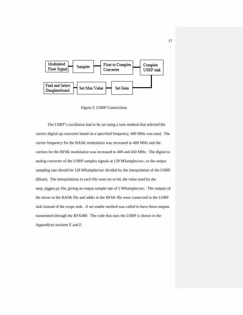
within a foot of each other. A diagram of these connections is shown in Figure 5.
17
Figure 5: USRP Connections
The USRP’s oscillation had to be set using a tune method that selected the
correct digital up converter based on a specified frequency, 400 MHz was used. The
carrier frequency for the BASK modulation was increased to 400 MHz and the
carriers for the BFSK modulation was increased to 400 and 450 MHz. The digital to
analog converter of the USRP samples signals at 128 MSamples/sec, so the output
sampling rate should be 128 MSamples/sec divided by the interpolation of the USRP
(Blum). The interpolations in each file were set to 64, the value used by the
usrp_siggen.py file, giving an output sample rate of 2 MSamples/sec. The outputs of
the mixer in the BASK file and adder in the BFSK file were connected to the USRP
sink instead of the scope sink. A set enable method was called to have these outputs
transmitted through the RFX400. The code that uses the USRP is shown in the
Appendices sections E and F.

18
IV. Test Plan
Initial tests were to verify that the USRP and RFX400 were functioning
properly and that GNU Radio was correctly installed. To verify the installation of
GNU Radio, the software in Appendices section A was installed onto a PC and a
phone tone file provided with the software was run.
To verify that the USRP would function with the computer that had GNU
Radio installed, which I will refer to as the host PC from this point forward, the
USRP was connected to the host PC and the location of the USRP drivers was entered
after the PC recognized the USRP so they would install on the USRP. The
usrp_siggen.py file was used to send a sine wave at 400 MHz, the lowest frequency in
the RFX400’s range, and a spectrum analyzer was used verify that a signal was being
sent at that frequency. A Fluke 6060B Synthesized RF Signal Generator was set to
generate a 400 MHz signal and a spectrum analyzer file, usrp_fft.py, was run to
verify that the RFX400 and USRP were capable of receiving signals. This was done
to prove that the USRP and the RFX400 were functioning properly and capable of
sending and receiving signals.
Binary frequency and amplitude shift keying modulation schemes were
implemented using python to show that the USRP could be used to modulate a signal.
A software oscilloscope, scope sink, was used to verify the modulations were correct.

19
The frequency of the BASK carrier was increased to 400 MHz. The BFSK carrier
frequencies were increased to 400 and 450 MHz. The message frequencies in each
file were increased to 1 MHz and the modulated signals were transmitted through the
RFX400. To maintain fidelity of the signals, the sample rate was increased to 64
MSamples/sec, the rate below the digital to analog converter rate of the USRP. The
maximum sampling rate of 128 MSamples/sec caused the host PC to process the
waveform at a slower rate. The usrp_scope.py file was used to show that the USRP
was able to receive modulated signals.
20
V. Test Results
GNU Radio did not fully install initially. An error during installation
said, "TypeError: 'NoneType' object is not iterable." A patch file,
cygwinccompiler.patch, was needed to fix the issue and after it was run, GNU Radio
was able to fully install (GNU Radio, “Wiki”). The phone tone file was run and
played a phone tone through the speakers of the host PC, proving that signals could
be processed on the computer but it’s functionality with the USRP was not verified.
The USRP was connected to the host PC and the drivers were successfully installed
onto the USRP. The 400 MHz signal generated by the usrp_siggen.py file appeared
on the spectrum analyzer as a 450 MHz signal. To further test this, the
usrp_siggen.py file was run again with a frequency of 350 MHz. Although the
USRP’s bandwidth is 400-500 MHz, the file ran without error. The spectrum
analyzer displayed a 400 MHz signal. This proved that there was a 50 MHz offset for
transmitted signals.
The usrp_fft.py file was run, but the center frequency was not able to set
consistently. Error messages would appear in the spectrum analyzer window that
said, “Failed,” after a center frequency was set. The inability of the board to set the
center frequency was intermittent and a clear explanation was unknown. After
inspecting the board and talking to the student who previously used the RFX400, it

21
was found that two 40 MHz clocks were added to the RFX400. The RFX400 needed
to use the USRP’s clock. After the clocks were removed, the signal generator file
created a signal at the correct frequency and the spectrum analyzer file, usrp_fft.py,
always set to the correct frequency.
The frequency and amplitude shift keying files were run and displayed the correct
waveforms in the scope windows, shown in Figures 6 and 7.
Figure 6: BASK Modulation
Figure 7: BFSK Modulation

22
The signals that the USRP received after the carrier frequencies were increased
did not resemble the ideal modulations. The FSK waveform before transmission is
shown in Figure 8 with the smallest time division that GNU Radio was capable of
producing. The received waveform is shown in Figure 9.
Figure 8: BFSK Waveform Before Transmission

23
Figure 9: BFSK After Reception By the USRP

24
VI. Conclusion and Recommendations
The USRP is an ideal system to use to learn about software defined radios in
an academic setting. The price of the board makes it more affordable than other
systems on the market and GNU Radio software can be used on any computer.
Testing is made easier when the hardware is not needed to view the signal prior to it
being transmitted. Just having GNU Radio software alone, signals can be processed
and tested on a student’s computer. The USRP and its daughterboard allow students
to learn about the effects of transmit power, gain, interpolation, decimation, and
transmission range on a received signal. The USRP and GNU Radio together are a
great platform to aid in understanding wireless systems and digital signal processing.
To help implement this into a larger setting, it is recommended that Linux is
used as the OS of the computers where GNU Radio is installed. This would eliminate
installation issues since many new GNU Radio components were meant to be used on
a Linux based OS. For example, files that need the USRP2 component will not run
on a Windows PC with Cygwin. For this to be used in a lab setting, students should
just use GNU Radio by itself to understand how the code works. After Python is
understood and students can modulate signals, then they should move onto
transmitting and receiving signals through the USRP. With the USRP’s analog to
digital converter only being able to sample 128 MSamples/sec, it is recommended to
get a front end board with decreased minimum and maximum frequencies. The

25
LFTX and LFRX daughterboards are made by Ettus and they have a range of
DC to 30 MHz. With these boards, sample rates will be high enough to no lose signal
information.
Those who wish to continue building on this project should try to transmit and
receive song files using different modulations and sampling rates. This would be
good to demo since attendees should be able to hear the differences in sample rates.
A two-way radio in the RFX400’s bandwidth could be used to transmit a person’s
voice and the USRP could be used to receive, demodulate, and play the signal
through a host PCs speakers.

26
VII. Bibliography
[1] FlexRadio Systems. What are Software Defined Radios? [Online]. Available:
http://www.flex-radio.com/About.aspx?topic=whatissdr
[2] WARP. (2011, April). WARP: Wireless Open Access Research Platform.
Available: http://warp.rice.edu/trac/
[3] M. Ettus. (2011, May 10). Ettus Research LLC [Online]. Available:
http://www.ettus.com
[4] SpinCore Technologies. (2011). PulseBlaster DDS-II-300 USB [Online].
Available: http://spincore.com/products/PulseBlasterDDS-II-
300/PulseBlasterDDS-II-300.shtml
[5] SpinCore Technologies. (2011). RadioProcessor. Available:
http://spincore.com/products/RadioProcessor/RadioProcessor.shtml
[6] BASIL Networks (2009). Multi-Channel DDS PCI Card [Online]. Available:
http://www.basilnetworks.com/article/pmgm130/pmgm130_Software_Overview.
htm
[7] GNU Radio. (2011, May 25). Wiki. Available:
http://gnuradio.org/redmine/wiki/gnuradio
[8] B. Padalino. (2007, June 15). FPGA in USRP [Online]. Available:
http://www.ruby-forum.com/topic/111921
[9] A. Ambardar, “Amplitude Modulations and Demodulations,” in Analog and
Digital Signal Processing, 2nd
Edition, California: Brooks/Cole Publishing
Company, 1999, pp. 300-321.
[10] B.P. Lathi and Z. Ding, “Principles of Digital Data Transmission,” in Modern
Digital and Analog Communication Systems, 4th
Edition, New York: Oxford
University Press, 2009, pp. 179.
[11] D. Shen. (2005, August 21). Tutorial 9: A Dictionary of the GNU Radio blocks
[Online]. pp. 2-9. Available:
http://omidi.iut.ac.ir/SDR/2007/WebPages/07_GNU/pdf/9.pdf

27
[12] J. Blum. Introductory Tour of the GNU Radio Project [Online]. Available:
http://www.joshknows.com/gnuradio
[13] GNU Radio. (2011, May 22). GNU Radio C++ Signal Processing Blocks
[Online]. Available: http://gnuradio.org/doc/doxygen/group__block.html
[14] M. Braun. (2009, January 16). GRC and unit of signal amplitude in USRP.
Available: http://www.ruby-forum.com/topic/175837
[15] B.P. Lathi and Z. Ding, “Principles of Digital Data Transmission,” in Modern
Digital and Analog Communication Systems, 4th
Edition, New York: Oxford
University Press, 2009, pp. 423-425.
28
VIII. Appendices
A. Program Listing
Cygwin
GNU Radio
Python 2.6
B. Parts List
1 USRP1
1 PC with Cygwin, GNU Radio, and Python 2.6 installed
1 RFX400
1 USB A/B cable
2 Motorola XTS5000 HT1000 UHF antennas
1 SMA cable
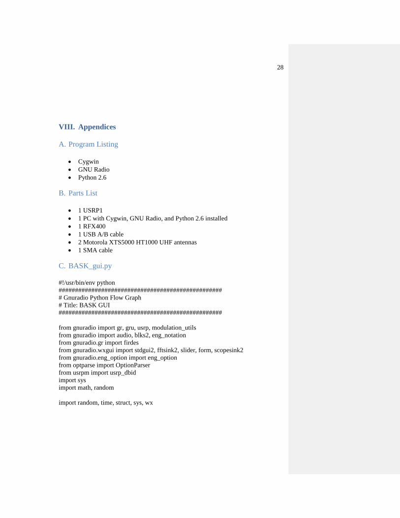
C. BASK_gui.py
#!/usr/bin/env python
##################################################
# Gnuradio Python Flow Graph
# Title: BASK GUI
##################################################
from gnuradio import gr, gru, usrp, modulation_utils
from gnuradio import audio, blks2, eng_notation
from gnuradio.gr import firdes
from gnuradio.wxgui import stdgui2, fftsink2, slider, form, scopesink2
from gnuradio.eng_option import eng_option
from optparse import OptionParser
from usrpm import usrp_dbid
import sys
import math, random
import random, time, struct, sys, wx

29
class my_top(stdgui2.std_top_block):
def __init__(self, frame, panel, vbox, argv):
stdgui2.std_top_block.__init__ (self, frame, panel, vbox, argv)
#Variables
sampling_freq = 10000
freq = 500
ampl = 100
src0 = gr.sig_source_f (sampling_freq, gr.GR_COS_WAVE, freq, ampl, 0)
src1 = gr.sig_source_f (sampling_freq, gr.GR_SQR_WAVE, 100, ampl, 0)
fm_mod = gr.frequency_modulator_fc (2*math.pi*freq)
throttle = gr.throttle(gr.sizeof_gr_complex, sampling_freq)
throttle1 = gr.throttle(gr.sizeof_float, sampling_freq)
mixer = gr.multiply_ff()
convert = gr.complex_to_float()
gain = gr.multiply_const_cc(4000)
scope = scopesink2.scope_sink_f(panel,"Input -> USRP", sampling_freq,
num_inputs=1 )
vbox.Add(scope.win,1,wx.EXPAND) #opens GUI box
self.connect(src1, (mixer,1))
self.connect(src0, (mixer,0))
self.connect(mixer, throttle1, scope)
if __name__ == '__main__':
app = stdgui2.stdapp(my_top, "Tx", nstatus=1)
app.MainLoop()
D. BFSK_gui.py
#!/usr/bin/env python
##################################################
# Gnuradio Python Flow Graph
# Title: BFSK GUI
##################################################
from gnuradio import gr, gru, usrp, modulation_utils
from gnuradio import audio, blks2, eng_notation
from gnuradio.gr import firdes
from gnuradio.wxgui import stdgui2, fftsink2, slider, form, scopesink2

30
from gnuradio.eng_option import eng_option
from optparse import OptionParser
from usrpm import usrp_dbid
import sys
import math, random
import random, time, struct, sys, wx
class my_top(stdgui2.std_top_block):
def __init__(self, frame, panel, vbox, argv):
stdgui2.std_top_block.__init__ (self, frame, panel, vbox, argv)
#Variables
sampling_freq = 10000
freq = 500
freq1 = 250
ampl = 100
#Sources
src0 = gr.sig_source_f (sampling_freq, gr.GR_COS_WAVE, freq, ampl, 0)
src1 = gr.sig_source_f (sampling_freq, gr.GR_SQR_WAVE, 100, ampl, 0)
src2 = gr.sig_source_f (sampling_freq, gr.GR_COS_WAVE, freq1, ampl, 0)
throttle = gr.throttle(gr.sizeof_gr_complex, sampling_freq)
throttle1 = gr.throttle(gr.sizeof_float, sampling_freq)
throttle2 = gr.throttle(gr.sizeof_float, sampling_freq)
mixer = gr.multiply_ff()
mixer1 = gr.multiply_ff()
adder = gr.add_ff()
gain = gr.multiply_const_cc(1000)
delay1 = gr.multiply_const_ff(1)
change = gr.multiply_const_ff(-1)
invert = gr.add_const_ff(ampl)
delay2 = gr.add_const_ff(0)
scope = scopesink2.scope_sink_f(panel,"Input -> USRP", sampling_freq,
num_inputs=1)
vbox.Add(scope.win,1,wx.EXPAND)
#delay square wave to maintain phase shift
self.connect(src1, delay1, delay2)
#Create a 1800 deg phase shift for square wave
self.connect(src1, change, invert)

31
self.connect(delay2, (mixer1,1))
self.connect(src0, (mixer1,0))
self.connect(mixer1, (adder, 0))
self.connect(invert, (mixer, 0))
self.connect(src2, (mixer,1))
self.connect(mixer, (adder, 1))
self.connect(adder, throttle1)
self.connect(throttle1, scope)
if __name__ == '__main__':
app = stdgui2.stdapp(my_top, "Tx", nstatus=1)
app.MainLoop()
E. BASK Using USRP
#!/usr/bin/env python
##################################################
# Gnuradio Python Flow Graph
# Title: BASK Using USRP
##################################################
from gnuradio import gr, gru, usrp, modulation_utils
from gnuradio import audio, blks2, eng_notation
from gnuradio.gr import firdes
from gnuradio.wxgui import stdgui2, fftsink2, slider, form, scopesink2
from gnuradio.eng_option import eng_option
from optparse import OptionParser
from usrpm import usrp_dbid
import sys
import math, random
import random, time, struct, sys, wx
class my_top_block(gr.top_block):
def __init__ (self):
gr.top_block.__init__(self)
#Variables
sampling_freq = 640000000
32
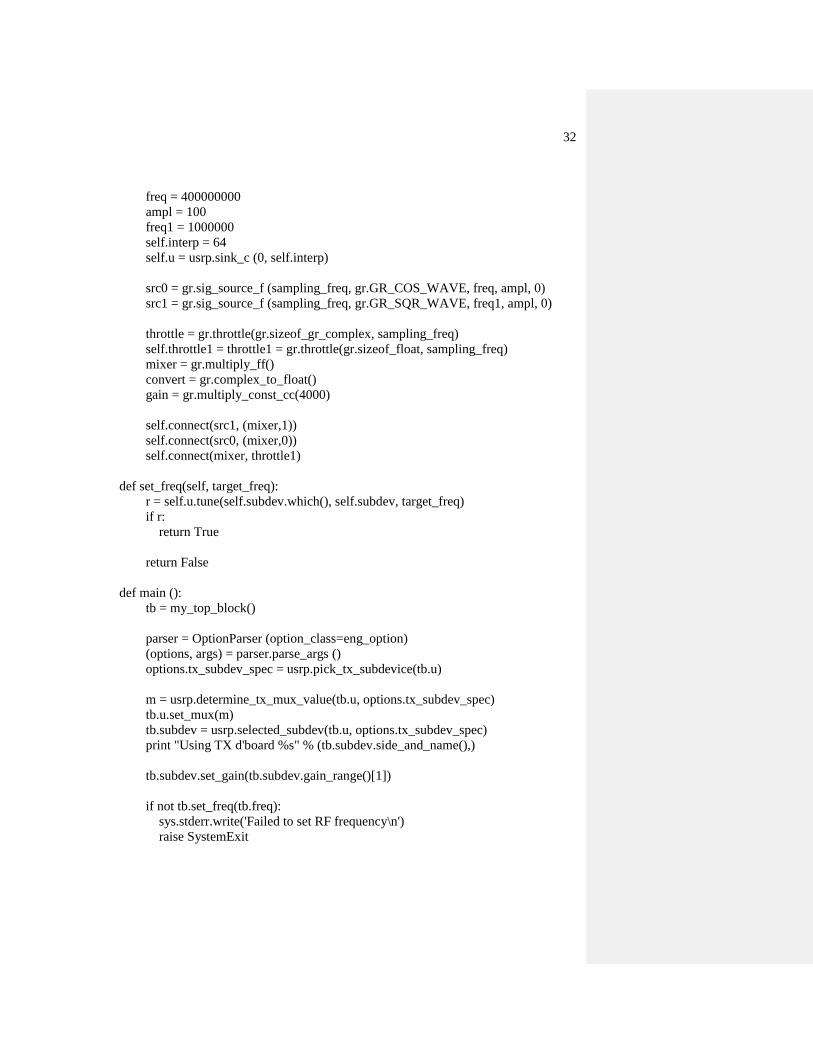
freq = 400000000
ampl = 100
freq1 = 1000000
self.interp = 64
self.u = usrp.sink_c (0, self.interp)
src0 = gr.sig_source_f (sampling_freq, gr.GR_COS_WAVE, freq, ampl, 0)
src1 = gr.sig_source_f (sampling_freq, gr.GR_SQR_WAVE, freq1, ampl, 0)
throttle = gr.throttle(gr.sizeof_gr_complex, sampling_freq)
self.throttle1 = throttle1 = gr.throttle(gr.sizeof_float, sampling_freq)
mixer = gr.multiply_ff()
convert = gr.complex_to_float()
gain = gr.multiply_const_cc(4000)
self.connect(src1, (mixer,1))
self.connect(src0, (mixer,0))
self.connect(mixer, throttle1)
def set_freq(self, target_freq):
r = self.u.tune(self.subdev.which(), self.subdev, target_freq)
if r:
return True
return False
def main ():
tb = my_top_block()
parser = OptionParser (option_class=eng_option)
(options, args) = parser.parse_args ()
options.tx_subdev_spec = usrp.pick_tx_subdevice(tb.u)
m = usrp.determine_tx_mux_value(tb.u, options.tx_subdev_spec)
tb.u.set_mux(m)
tb.subdev = usrp.selected_subdev(tb.u, options.tx_subdev_spec)
print "Using TX d'board %s" % (tb.subdev.side_and_name(),)
tb.subdev.set_gain(tb.subdev.gain_range()[1])
if not tb.set_freq(tb.freq):
sys.stderr.write('Failed to set RF frequency\n')
raise SystemExit

33
convert = gr.float_to_complex()
tb.connect(tb.throttle1, convert, tb.u)
tb.subdev.set_enable(True) # enable transmitter
try:
tb.run()
except KeyboardInterrupt:
pass
if __name__ == '__main__':
main()
F. BFSK Using USRP
#!/usr/bin/env python
##################################################
# Gnuradio Python Flow Graph
# Title: GUI
##################################################
from gnuradio import gr, gru, usrp, modulation_utils
from gnuradio import audio, blks2, eng_notation
from gnuradio.gr import firdes
from gnuradio.wxgui import stdgui2, fftsink2, slider, form, scopesink2
from gnuradio.eng_option import eng_option
from optparse import OptionParser
from usrpm import usrp_dbid
import sys
import math, random
import random, time, struct, sys, wx
class my_top_block(gr.top_block):
def __init__ (self):
gr.top_block.__init__(self)
#Variables
self.samp_rate = sampling_freq = 640000000
self.freq = freq = 400000000
self.freq1 = freq1 = freq+50000000
ampl = 100
#For USRP:
self.interp = 64
self.u = usrp.sink_c (0, self.interp)

34
#Sources
src0 = gr.sig_source_f (sampling_freq, gr.GR_COS_WAVE, freq, ampl, 0)
src1 = gr.sig_source_f (sampling_freq, gr.GR_SQR_WAVE, 2000000, ampl, 0)
src2 = gr.sig_source_f (sampling_freq, gr.GR_COS_WAVE, freq1, ampl, 0)
throttle = gr.throttle(gr.sizeof_gr_complex, sampling_freq)
self.throttle1 = throttle1 = gr.throttle(gr.sizeof_float, sampling_freq)
throttle2 = gr.throttle(gr.sizeof_float, sampling_freq)
mixer = gr.multiply_ff()
mixer1 = gr.multiply_ff()
adder = gr.add_ff()
gain = gr.multiply_const_cc(1000)
delay1 = gr.multiply_const_ff(1)
change = gr.multiply_const_ff(-1)
invert = gr.add_const_ff(ampl)
delay2 = gr.add_const_ff(0)
#Create a 90 deg phase shift for square wave
#delay square wave to maintain phase shift
self.connect(src1, delay1, delay2)
self.connect(src1, change, invert)
self.connect(delay2, (mixer1,1))
self.connect(src0, (mixer1,0))
self.connect(mixer1, (adder, 0))
self.connect(invert, (mixer, 0))
self.connect(src2, (mixer,1))
self.connect(mixer, (adder, 1))
self.connect(adder, throttle1)
def set_freq(self, target_freq):
r = self.u.tune(self.subdev.which(), self.subdev, target_freq)
if r:
return True
return False
def main ():
tb = my_top_block()
parser = OptionParser (option_class=eng_option)
35
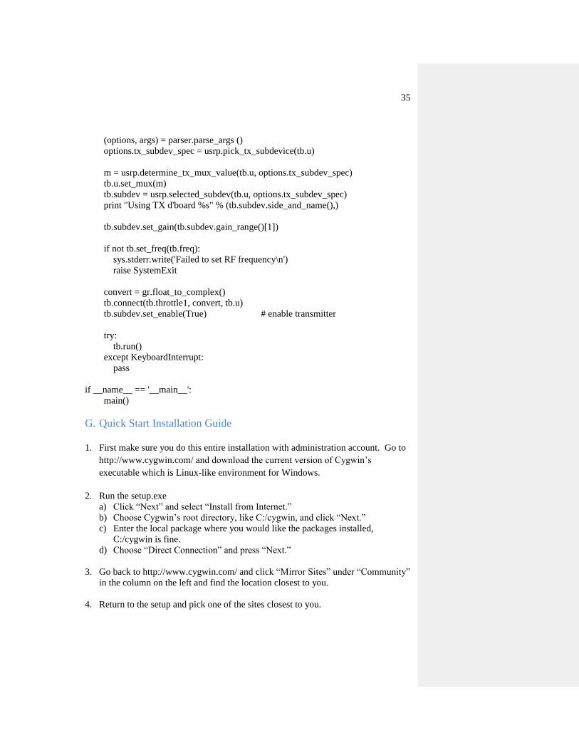
(options, args) = parser.parse_args ()
options.tx_subdev_spec = usrp.pick_tx_subdevice(tb.u)
m = usrp.determine_tx_mux_value(tb.u, options.tx_subdev_spec)
tb.u.set_mux(m)
tb.subdev = usrp.selected_subdev(tb.u, options.tx_subdev_spec)
print "Using TX d'board %s" % (tb.subdev.side_and_name(),)
tb.subdev.set_gain(tb.subdev.gain_range()[1])
if not tb.set_freq(tb.freq):
sys.stderr.write('Failed to set RF frequency\n')
raise SystemExit
convert = gr.float_to_complex()
tb.connect(tb.throttle1, convert, tb.u)
tb.subdev.set_enable(True) # enable transmitter
try:
tb.run()
except KeyboardInterrupt:
pass
if __name__ == '__main__':
main()
G. Quick Start Installation Guide
1. First make sure you do this entire installation with administration account. Go to
http://www.cygwin.com/ and download the current version of Cygwin’s
executable which is Linux-like environment for Windows.
2. Run the setup.exe
a) Click “Next” and select “Install from Internet.”
b) Choose Cygwin’s root directory, like C:/cygwin, and click “Next.”
c) Enter the local package where you would like the packages installed,
C:/cygwin is fine.
d) Choose “Direct Connection” and press “Next.”
3. Go back to http://www.cygwin.com/ and click “Mirror Sites” under “Community”
in the column on the left and find the location closest to you.
4. Return to the setup and pick one of the sites closest to you.

36
5. Click “Next,” a window like Figure 10 should appear, and select:
cppunit 1.12.0-1 (1.12.1 doesn't work)
gcc-g++ (3.4.4 works, but 4.3.4 does not)
gsl-devel
guile
libfftw3-devel
libtool (version 2.2 or later)
libusb-win32
make
patch
pkg-config
python (get 2.6)
python-numpy
swig
util-linux
Figure 10: gcc-g++ Location
6. Click “Next” until the installations are finished.
7. Go to http://www.wxpython.org/download.php#sources and download wxPython
for Python 2.6 to the /usr/src. Go to

37
http://sourceforge.net/projects/boost/files/boost/1.45.0/ to download
boost_1_45_0.tar.bz2 to the /usr/src. Go to
http://www.portaudio.com/download.html to download the current v19 stable
release to /usr/src. Go to http://sourceforge.net/projects/sdcc/files/, click sdcc-
win32 and download sdcc-2.9.0-setup.exe to /usr/src.
8. Run Cygwin, click on the desktop icon if installed. If not, click on Cygwin.bat in
Cygwin’s root folder. This will open a Cygwin window. The window opening
verifies that Cygwin was properly installed.
9. Go to the /usr/src folder and run sdcc-2.9.0-setup.exe. In Cygwin enter:
which sdcc
The path to sdcc should be shown, if not type:
PATH= “PATH:/c/Program Files/SDCC/bin”
10. In Cygwin, go to src folder by entering:
cd /usr/src
tar –zxf pa_stable.tgz
Your actual filename may be different, so enter whatever you called that file.
This command extracts the files in the compressed folder. In Cygwin, enter:
cd portaudio
./configure -- disable-static
make
make install
This installs PortAudio on your PC with the static component disabled.
11. Extract wxPython by entering:
tar –jxf wxPython-src-2.8.11.0.tar.bz2
export WXDIR=/usr/src/wxPython-src-2.8.11.0
cd $WXDIR
mkdir build-local
This set of commands extracts the files fromwxPython-src-2.8.11.0, creates a
shortcut to the directory that was extracted, moves you into that directory, and
creates a directory called build-local. Configure the wxWidgets by entering:
cd $WXDIR/build-local
../configure --with-msw
38
With wxPython 2.8.11.0, a couple of patches need to be applied. Open the
setup.h file in build-local/lib/wx/include/msw-ansi-release-2.8/wx/. After the
line(line 322):
#define wxUSE_DATEPICKCTRL 1
Add:
#define wxUSE_DATEPICKCTRL_GENERIC 1
12. Go to https://sites.google.com/site/theprogressiveusrp/file-cabinet and download
the cygwinccompiler.patch file, save it to the /usr/lib/python2.6/disutils folder.
13. Go back to the Cygwin window and enter:
cd /usr/lib/python2.6/disutils
patch –i cygwinccompiler.patch
14. Compile the wxWidgets by entering:
cd $WXDIR/build-local
make
make –C contrib/src/stc
If you get and error about conflicts between winsock.h and select.h, enter:
cd /usr/include/sys
mv select.h select.h-x
This renames the select.h file select.h-x. Run the make command at the
beginning of this step again. After it is finished, rename the file to its original
name. To do this enter:
cd /usr/include/sys
mv select.h-x select.h
15. Install the wxWidgets by entering:
cd $WXDIR/build-local
make install
make –C contrib/src/stc install
16. Move the DLLs that were installed in the /usr/local/lib/ to the /usr/local/bin folder.
Enter:
mv /usr/local/lib/cygwx*.dll /usr/local/bin
17. Verify that wxWidgets was installed properly by entering:
cd $WXDIR/build-local/samples/minimal
make
./minimal.exe

39
An empty window should appear.
18. Now to link Python to the wxWidgets enter:
cd $WXDIR /wxPython
python setup.py build_ext ---inplace WXPORT=msw COMPILER=cygwin
BUILD_GLCANVAS=0 BUILD_GIZMOS=0 UNICODE=0
19. Install wxPython, enter:
cd $WXDIR/wxPython
python setup.py install WXPORT=msw COMPILER=cygwin
BUILD_GLCANVAS=0 BUILD_GIZMOS=0 UNICODE=
20. Test this installation by entering:
cd $WXDIR/wxPython/demo
python demo.py
A window with a green snake should pop up, shown in Figure 11. These
components on GNU Radio will be used later, so it’s important that these are
installed properly. Cygwin should now resemble Figure 12.
Figure 11: The WxPython Window

40
Figure 12: The Cygwin Window After demo.py File Is Run
21. Install boost by entering:
cd /usr/src
tar –jxf boost_1_45_0.tar.bz2
cd boost_1_45_0
./bootstrap.sh –with-libraries=thread,date_time,program_options
./bjam install
This installation takes a while.
22. Go to ftp://ftp.gnu.org/gnu/gnuradio/gnuradio-3.3.0.tar.gz to download the GNU
Radio source code to a convenient directory, I chose the /usr/src folder. Unpack
this file by going to Cygwin and navigating to the directory where you
downloaded the tarball and enter:
tar –zxf gnuradio-3.3.0.tar.gz
23. Add the pkg-config folder to your Path list by entering:
export PKG_CONFIG_PATH=/usr/local/lib/pkgconfig
41
24. The actual installation of GNU Radio will be done twice. The first installation
will have most components disabled so that you can GNU Radio, the libraries,
and other utilities were installed properly quickly. To do this, enter:
cd gnuradio-3.3.0
./configure --disable-all-components --enable-gruel --enable-gnuradio-core --
enable-gr-audio-oss
25. To actually install GNU Radio, enter:
make
make check
make install
If you’ve received and errors, not warnings, go to
http://gnuradio.org/redmine/wiki/gnuradio/WindowsTips and see if your problem
is documented.
26. To verify the installation and play an audio file, make sure that your speakers are
turned on and that “wave” sound files aren’t disabled. Next, enter:
export PYTHONPATH=/usr/local/lib/python2.6/site-packages
cd gnuradio-examples/python/audio
python dial_tone.py
This should play a dial tone. For this and every file ran in Cygwin, press Ctrl-
C to stop it. If you receive an error, then something went wrong during the
installation. Verify that you’ve installed all the libraries and utilities that were
previously mentioned.
27. The full version of GNU Radio can now be built. Know that this takes a long
time to do and you may even want to do this overnight. To build a full GNU
Radio system will all components, enter:
cd gnuradio-3.3.0
./configure
make
make check
make install
After this finishes, a full GNU Radio system will be installed on your
computer and Cygwin should resemble Figure 13. Your computer is now ready to
process signals.

42
Figure 13: Cygwin After GNU Radio Installation1
1 gr-utils and wx-gui should not be skipped

43
28. Lastly, you need to verify that your computer recognizes the USRP. Move the
USRP’s driver filebs to GNU Radio’s root folder. In Cygwin, go to the gnuradio-
3.3.0 folder, where ever you installed it and enter:
cd usrp
cp /usr/lib/libusb/libusb0.sys
cp /usr/bin/cygusb0.dll libusb0.dll
Power on the USRP by plugging it into an outlet, then connect it to the host
PC via the USB cable. A “Found New Hardware” balloon should appear. Click
on it and go through the menus by selecting no, not this time (do not connect to
Windows Update), Install from a list of specific location (Advanced), and Search
for the best driver. In the last page with Search for the best driver, uncheck
“Search removable media” and include the path to the gnuradio-3.3.0/usrp folder.
The driver files should be found.
When you need to remove the USRP, always use the safely remove hardware
option. After the host PC says that it is safe to remove the hardware, remove the
USB cable. It is now safe to unplug the USRP.
H. Signal Transmission Lab Pre-lab: Go to http://www.joshknows.com/gnuradio and
http://gnuradio.org/doc/doxygen/group__block.html to read the necessary GNU
Radio information. What line of code is used to connect GNU Radio components?
Self.connect(component1, component2) What line of code create a signal source, such as a saw wave, and how is the signal
type (float, complex, etc.) controlled? gr.sig_source_signaltype, the signal is f for
float, c for complex, I for integer, or s for short. What is required for a complete GNU Radio Python file? At least one source and one
sink is required. They must be directly or indirectly connected to one another. What is a signals minimum sample rate in terms of its frequency? The sample rate
must be at least twice the frequency. Give example code for a sink that plays the source signal through the computer

44
speakers, connects to a USRP1, and does nothing. Variable_name = audio.sink(freq),
variable_name = usrp.sink_s(0) or usrp.sink_c(0), and variable_name =
gr.null_sink(data stream size) Create two sawtooth signal sources that get sent through a mixer and the output is
played through your speakers. Ensure that the signal output is in the audible range. From gnuradio import gr src0 = gr.sig_source_f (sampling_freq, gr.GR_COS_WAVE, freq0, amplitude, offset) src1 = gr.sig_source_f (sampling_freq, gr.GR_COS_WAVE, freq1, amplitude, offset) mixer = gr.multiply_ff() sink = audio.sink(sampling_freq) self.connect(src0, (mixer, 0)) self.connect(src1, (mixer,1)) self.connect(mixer, sink) References: http://gnuradio.org/redmine/wiki/1/TutorialsWritePythonApplications Objective: To get introduced to the GNU Radio software and learn how to transmit through the
USRP. Introduction: GNU Radio is a free software package that allows signals to be processed on a
computer and runs independent of any RF hardware, but is set up to interface with the
USRP. In this lab, you will be using this software and the knowledge gained from the
pre-lab to send your own audible signal through the USRP. Procedure:
1. Open a text or Python code editor, and using the code from the pre-lab, create
the file from the last question and see if any audio is played. Remember, in
python classes are created but classes aren’t run automatically, they need to be
called. For example, to create a class using the GNU Radio top_block class,
enter this:

45
class my_top_block(gr.top_block):
def __init__ (self): gr.top_block.__init__(self)
#code..
To call this class create a variable with a reference to this class and then it can be
run.
tb = my_top_block() tb.run()
2. Now use the references from the pre-lab and create a scope and fft sink to show
and oscilloscope and spectrum analyzer display. Include these in the lab report
along with a quick explanation as to how you know the displays are correct. 3. Remove the scope sinks and create a usrp_c sink. The input to a sink must be the
same type. GNU Radio provedes a few converters under gr components. How do
you convert a float signal to a complex signal? converter = gr.float_to_complex() self.connect(float_signal, converter) self.connect(converter, complex_signal) 4. Use the code in the code appendix to help you communicate with the USRP. You
don’t have to fully understand it now. Just know that it allows the code to talk
with the daughterboard on the USRP. Make sure that the input of the USRP is
within the frequency range of the daughterboard. 5. Use the usrp_fft.py and usrp_scope.py files under the gr-utils directory to get a
waveform and frequency spectrum display and include these in the report. Note any
differences between these displays and the previous displays from step 2.
Code Appendix: def set_freq(self, target_freq): r = self.u.tune(self.subdev.which(), self.subdev, target_freq) #self.u.set_frequency(FM_freq) #self.src.set_frequency(self.freq) if r:

46
return True return False def main (): tb = my_top_block() parser = OptionParser (option_class=eng_option) (options, args) = parser.parse_args () options.tx_subdev_spec = usrp.pick_tx_subdevice(tb.u) m = usrp.determine_tx_mux_value(tb.u, options.tx_subdev_spec) tb.u.set_mux(m) tb.subdev = usrp.selected_subdev(tb.u, options.tx_subdev_spec) print "Using TX d'board %s" % (tb.subdev.side_and_name(),) tb.subdev.set_gain(tb.subdev.gain_range()[1]) if not tb.set_freq(tb.freq): sys.stderr.write('Failed to set RF frequency\n') raise SystemExit convert = gr.float_to_complex() tb.connect(tb.throttle1, convert, tb.u) tb.subdev.set_enable(True) # enable transmitter try: tb.run() except KeyboardInterrupt: pass if __name__ == '__main__': main()