digital networks classification paolo prinetto politecnico di torino (italy) university of illinois...
TRANSCRIPT

Digital networksDigital networksclassificationclassification
Digital networksDigital networksclassificationclassification
Paolo PRINETTOPolitecnico di Torino (Italy)
University of Illinois at Chicago, IL (USA)
[email protected] [email protected]
www.testgroup.polito.it
Lecture
4.1

2 4.1
Goal
This lecture introduces a taxonomy on digital networks, focusing, in particular, on:
Combinational vs. sequential
Mealy vs. Moore
I/O clustering.

3 4.1
Prerequisites
Module 3

4 4.1
Homework
No particular homework is foreseen

5 4.1
Further readings
No particular suggestion

6 4.1
OutlineOutline
Combinational vs. sequential networks
Moore vs. Mealy machines
I/O clustering.

7 4.1
Some graphic conventions
Hereinafter:
will identify a bus or a set of wires
will identify a single bit wire
8 4.1
Digital network
A proper assembly of electronic devices, designed to store,
transform, and communicate information
in digital form

9 4.1
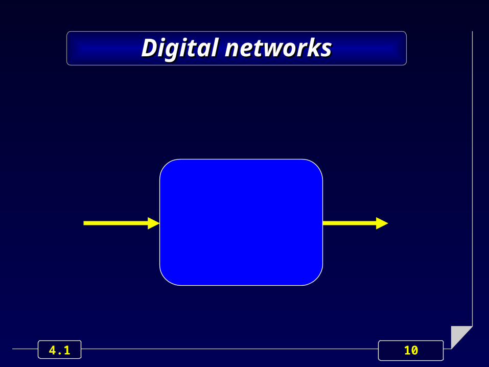
Digital networksDigital networks
10 4.1
Digital networksDigital networks
11 4.1
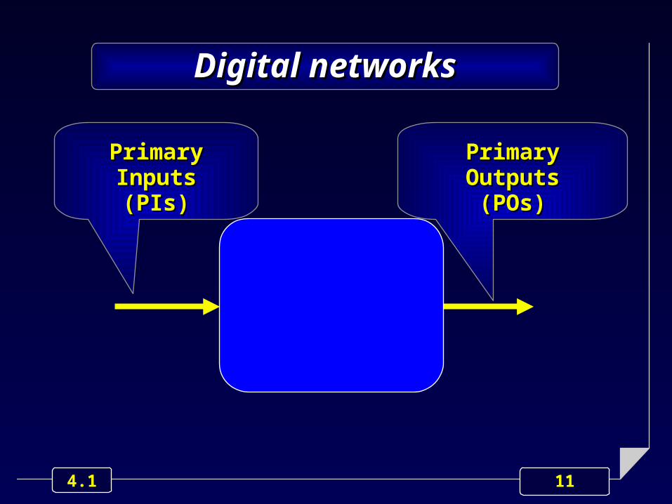
Digital networksDigital networks
Primary InputsPrimary Inputs(PIs)(PIs)
Primary OutputsPrimary Outputs(POs)(POs)

12 4.1
Digital networksDigital networks
Digital networks are Digital networks are usually classified as:usually classified as:
• combinationalcombinational• sequentialsequential

13 4.1
A digital network is combinational
iff its POs are completely
determined by its present PIs, only.
Combinational network
Abstractionlevels
systemsystem
RT
logic
device
behavior structure physic geometry
Abstractionlevels
systemsystem
RT
logic
device
behavior structure physic geometry
Abstractionlevels
systemsystem
RT
logic
device
behavior structure physic geometry
14 4.1
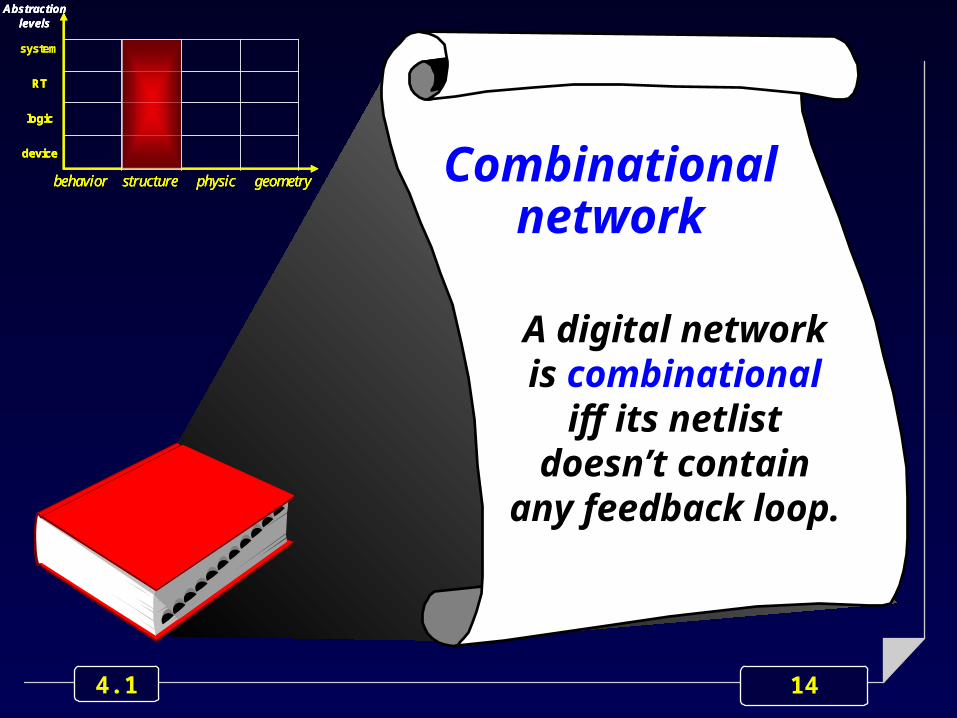
A digital network is combinational
iff its netlist doesn’t contain any feedback
loop.
Combinational network
Abstractionlevels
systemsystem
RT
logic
device
behavior structure physic geometry
Abstractionlevels
systemsystem
RT
logic
device
behavior structure physic geometry
Abstractionlevels
systemsystem
RT
logic
device
behavior structure physic geometry
15 4.1
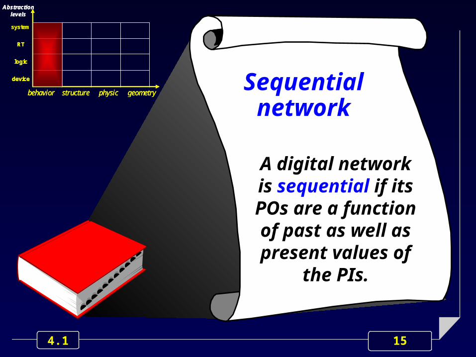
A digital network is sequential if its POs are a function of past as well as present values of
the PIs.
Sequential network
Abstractionlevels
systemsystem
RT
logic
device
behavior structure physic geometry
Abstractionlevels
systemsystem
RT
logic
device
behavior structure physic geometry
Abstractionlevels
systemsystem
RT
logic
device
behavior structure physic geometry

16 4.1
A digital network is sequential if its netlist contains one, or more,
feedback loops.
Sequential network
Abstractionlevels
systemsystem
RT
logic
device
behavior structure physic geometry
Abstractionlevels
systemsystem
RT
logic
device
behavior structure physic geometry
Abstractionlevels
systemsystem
RT
logic
device
behavior structure physic geometry
1

17 4.1
An example
S
R

18 4.1
An example
S
RS
R
Feedback

19 4.1
The concept of state
A sequential circuit must be able to “remember”, or “store”, some information items related to the values the PIs have got.
Such a storing capability is accomplished in terms of “internal states”: in any instant, the circuits is in a well defined “state”, univocally represented by the values got by the set of “internal state variables”.
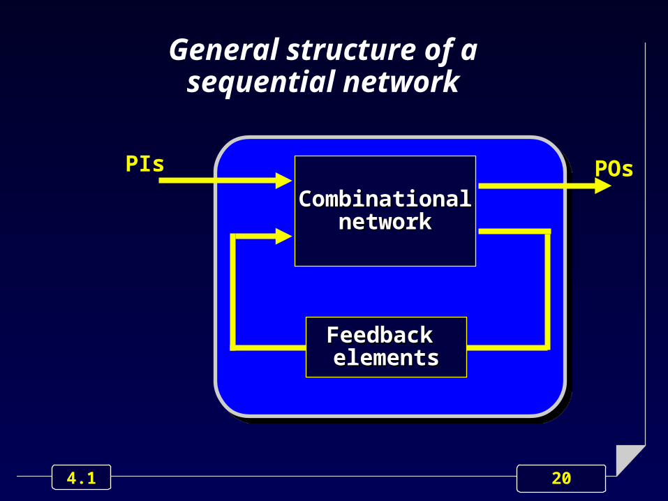
20 4.1
General structure of a sequential network
CombinationalCombinationalnetworknetwork
PIs POs
Feedback Feedback elementselements
21 4.1
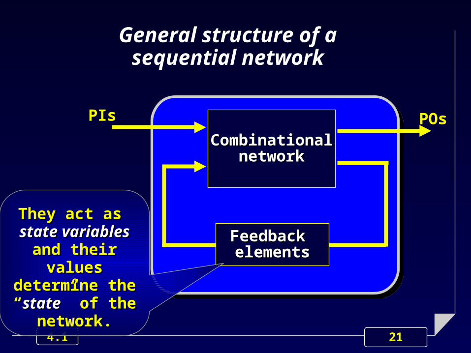
General structure of a sequential network
CombinationalCombinationalnetworknetwork
PIs POs
Feedback Feedback elementselements
They act as They act as state variablesstate variables
and their values and their values determine the determine the ““statestate” of the ” of the
network.network.

22 4.1
General structure of a sequential network
CombinationalCombinationalnetworknetwork
PIs POs
Feedback Feedback elementselements
Present-state Present-state variablesvariables
oror
Secondary Secondary InputsInputs
23 4.1
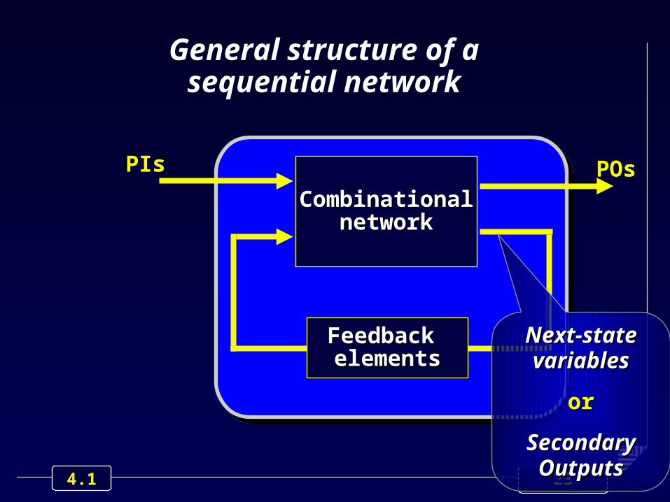
General structure of a sequential network
CombinationalCombinationalnetworknetwork
PIs POs
Feedback Feedback elementselements
Next-state Next-state variablesvariables
oror
Secondary Secondary OutputsOutputs

24 4.1
State variables
A sequential network has as many state variables as feedback elements
A network with n state variables is characterized by 2 n possible states.

25 4.1
Sequential network classification
CombinationalCombinationalnetworknetwork
PIs POs
Feedback Feedback elementselements

26 4.1
Sequential network classification
CombinationalCombinationalnetworknetwork
PIs POs
Feedback Feedback elementselements
According to the “feedback According to the “feedback elements” nature, sequential elements” nature, sequential networks are classified as:networks are classified as:
• asynchronousasynchronous
• synchronoussynchronous

27 4.1
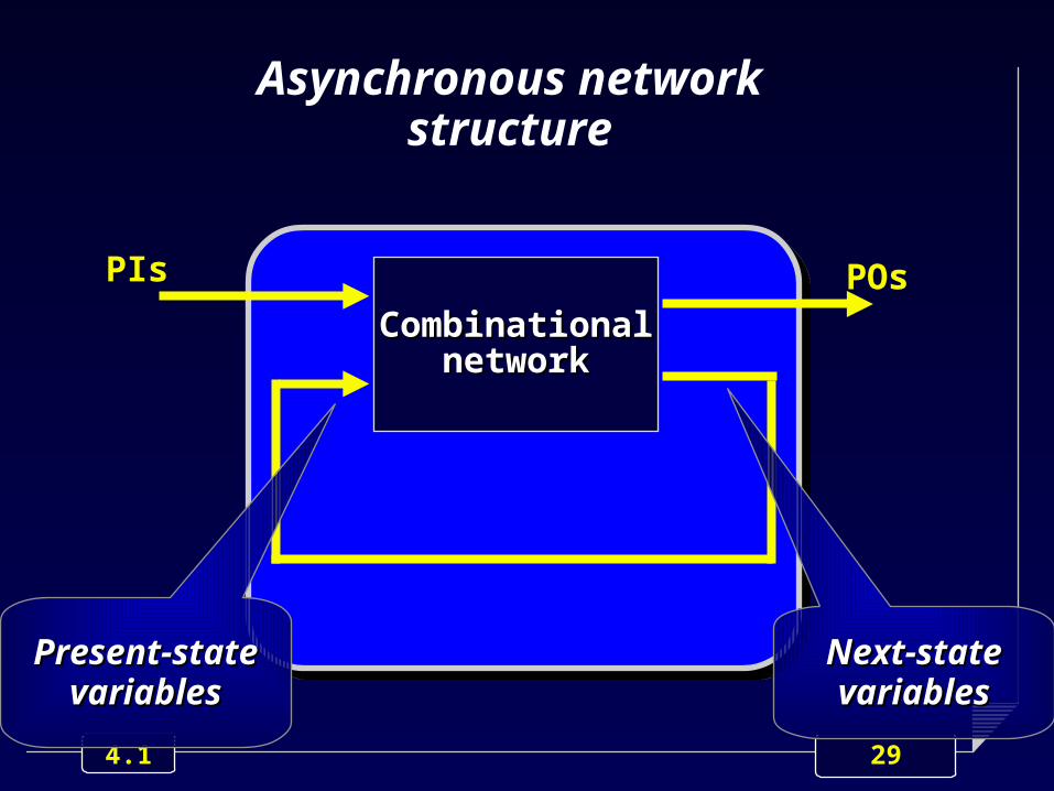
Asynchronous networks
Each feedback element is just a wire.
The information flow through feedback elements is a continuum and not synchronizedsynchronized by any external event.

28 4.1
Asynchronous network structure
CombinationalCombinationalnetworknetwork
PIs POs
29 4.1
Asynchronous network structure
CombinationalCombinationalnetworknetwork
PIs POs
Present-state Present-state variablesvariables
Next-state Next-state variablesvariables

30 4.1
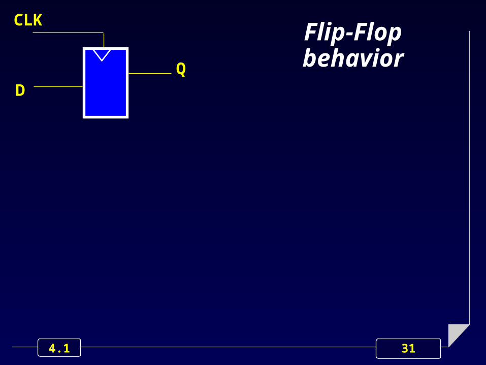
Synchronous networks
Each feedback is always performed via a particular device, named Flip-Flop.
Flip-Flop behavior is controlled and timed by an ad-hoc signal, usually referred to as clock.
The information flow through the feedback elements is thus “synchronized” by the clock.
31 4.1
DQ
CLKFlip-Flopbehavior
32 4.1
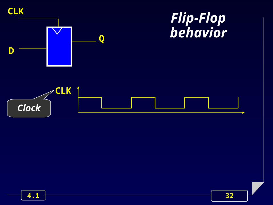
CLK
DQ
CLK
Clock
Flip-Flopbehavior
33 4.1
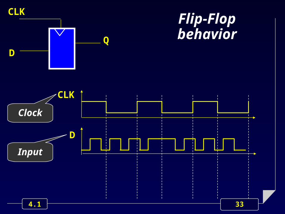
CLK
D
DQ
CLK
Clock
Input
Flip-Flopbehavior

34 4.1
CLK
D
Q
DQ
CLK
Clock
Input
Output
Flip-Flopbehavior

35 4.1
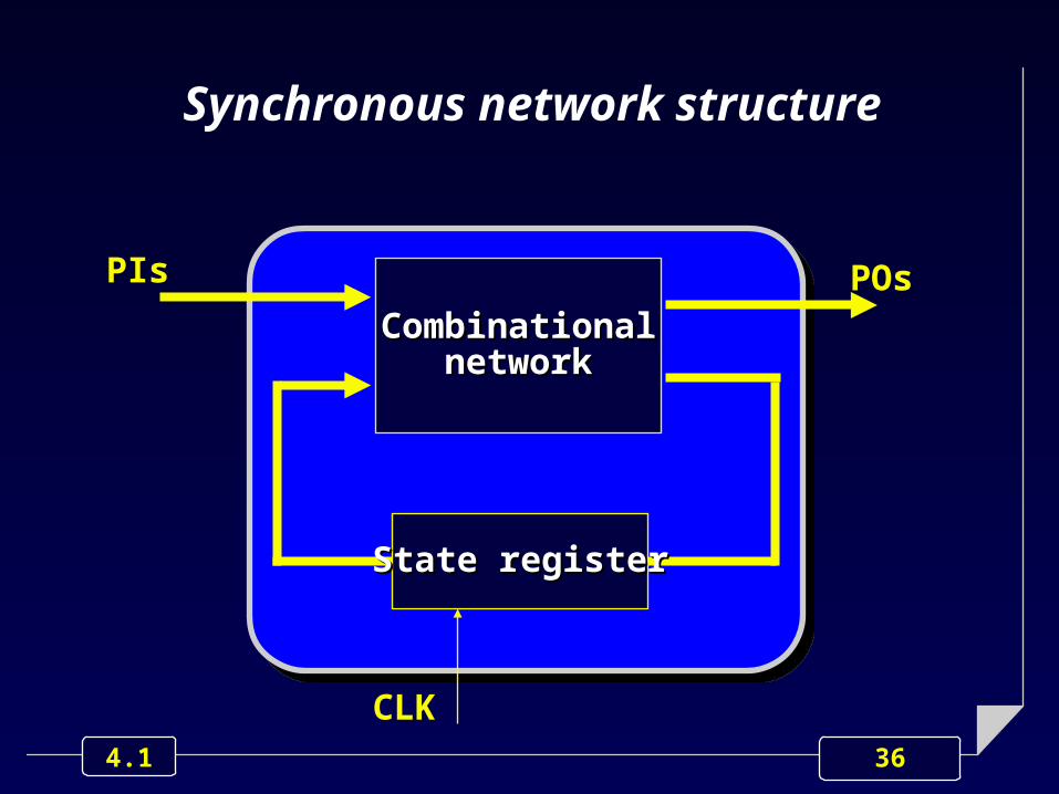
State register
The set of Flip-Flops is often referred to as “State Register”, since it stores the network state variables.
36 4.1
Synchronous network structure
CombinationalCombinationalnetworknetwork
PIs POs
State registerState register
CLK
37 4.1
Finite State Machines
Synchronous networks, being characterized by a finite # of flip-flops, and thus of states, are very often referred to as Finite State Machines Finite State Machines (FSMs).

38 4.1
Reset signal & Reset state
Any FSM, regardless its complexity, must have:
a particular control input signal, named reset signal (or simply reset) characterized by the highest priority
a particular state, named reset state, in which the network moves whenever the reset signal is asserted.

39 4.1
Asynchronous reset
CombinationalCombinationalnetworknetwork
PIs POs
State registerState register
CLK reset
40 4.1
OutlineOutline
Combinational vs. sequential networks
Moore vs. Mealy machines
I/O clustering.

41 4.1
Combinational network splitting
CombinationalCombinationalnetworknetwork
PIs POs
State registerState register
CLK reset

42 4.1
Combinational network splitting
CombinationalCombinationalnetworknetwork
PIs POs
State registerState register
CLK reset
Can be split in two Can be split in two independent networksindependent networks

43 4.1
Next state network
State register
CLK
Primary Output network
reset
PIs POs

44 4.1
Next state network
State register
CLK
Primary Output network
The structure of this The structure of this network allows us to network allows us to distinguish between:distinguish between:• Moore machinesMoore machines• Mealy machinesMealy machines
reset
PIs POs

45 4.1
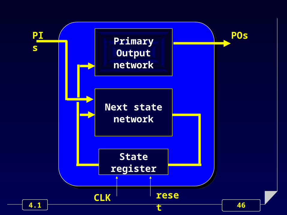
Moore machines
POs depend on the present state value, only.
POs can change only when state changes.
46 4.1
Next state network
State register
PIs POs
CLK
Primary Output network
reset
47 4.1
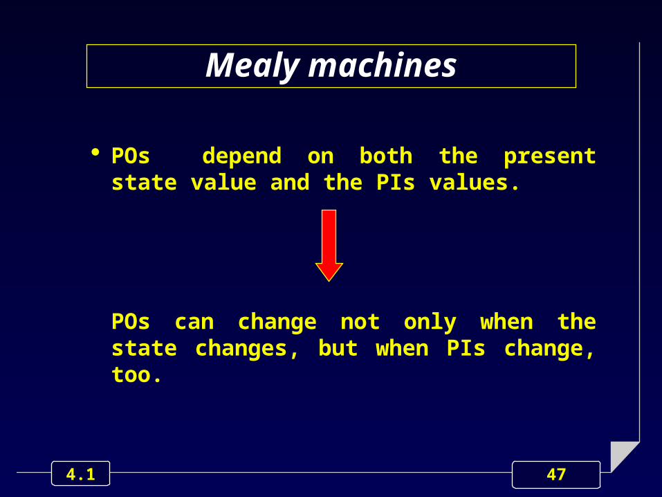
Mealy machines
POs depend on both the present state value and the PIs values.
POs can change not only when the state changes, but when PIs change, too.

48 4.1
PI PO
CLK RESET
Next state network
State register
Primary Output network

49 4.1
OutlineOutline
Combinational vs. sequential networks
Moore vs. Mealy machines
I/O clustering.

50 4.1
Digital networks I/O Digital networks I/O clusteringclustering
I/O pins of digital networks are usually clustered in 3 main categories:
Data I/Os
Clock I/Os
Control I/Os.

51 4.1
Digital networks I/O Digital networks I/O clusteringclustering

52 4.1
Data I/OsData I/Os
Data InputsData Inputs Data OutputsData Outputs

53 4.1
Clock I/OsClock I/Os
Clock InputsClock Inputs

54 4.1
Clock I/OsClock I/Os
Clock InputsClock Inputs
They synchronize the overall behavior They synchronize the overall behavior of the network by:of the network by:
samplingsampling data and control inputs data and control inputsupdatingupdating data and control outputs data and control outputs

55 4.1
Edge vs. pulse triggering
Sampling and updating can be triggered by clock’s
raising or falling edges
positive or negative pulses.
56 4.1
Edge triggering behavior
The same clock edge samples the inputs and concurrently updates the outputs:
raising edge positive edge triggered
falling edge negative edge triggered.
57 4.1
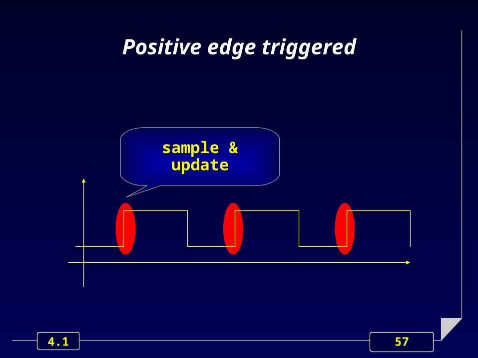
Positive edge triggered
sample &sample &updateupdate

58 4.1
Clock
D
Q
Positive edge triggered

59 4.1
Clock
D
Q
Positive edge triggered

60 4.1
Clock
D
Q
Positive edge triggered
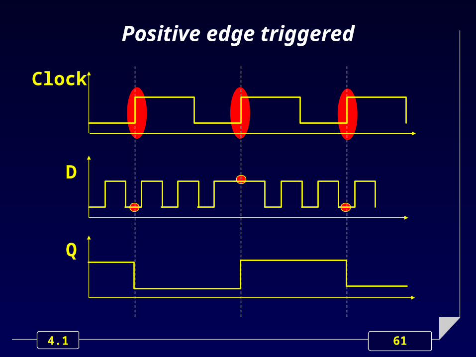
61 4.1
Clock
D
Q
Positive edge triggered

62 4.1
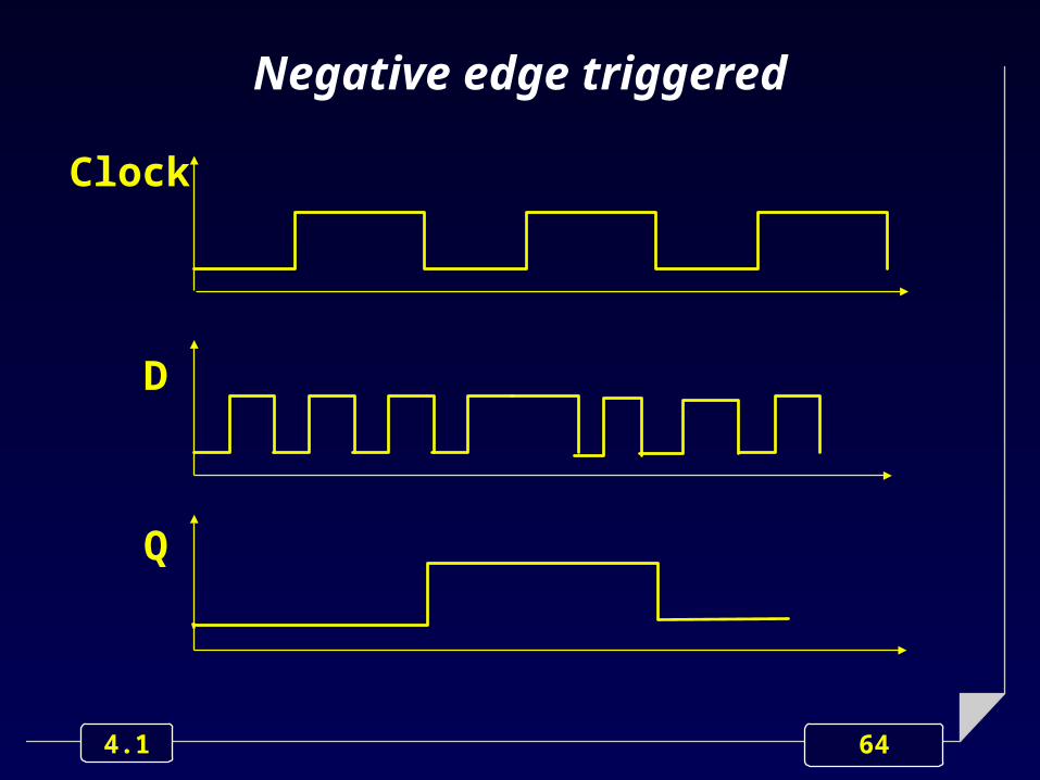
Negative edge triggered
sample &sample &updateupdate

63 4.1
Negative edge triggered
64 4.1
Clock
D
Q
Negative edge triggered
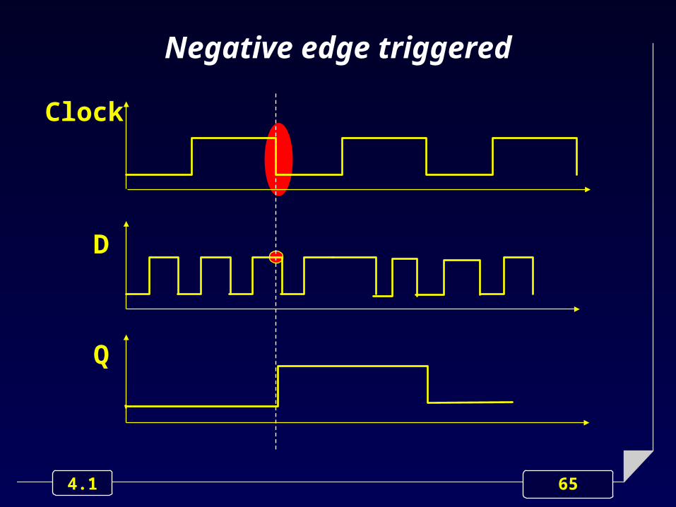
65 4.1
Clock
D
Q
Negative edge triggered

66 4.1
Clock
D
Q
Negative edge triggered

67 4.1
Pulse triggering behavior
An edge of the clock samples the inputs values and the other edge updates the outputs.

68 4.1
Positive pulse triggered

69 4.1
Positive pulse triggered
samplesample
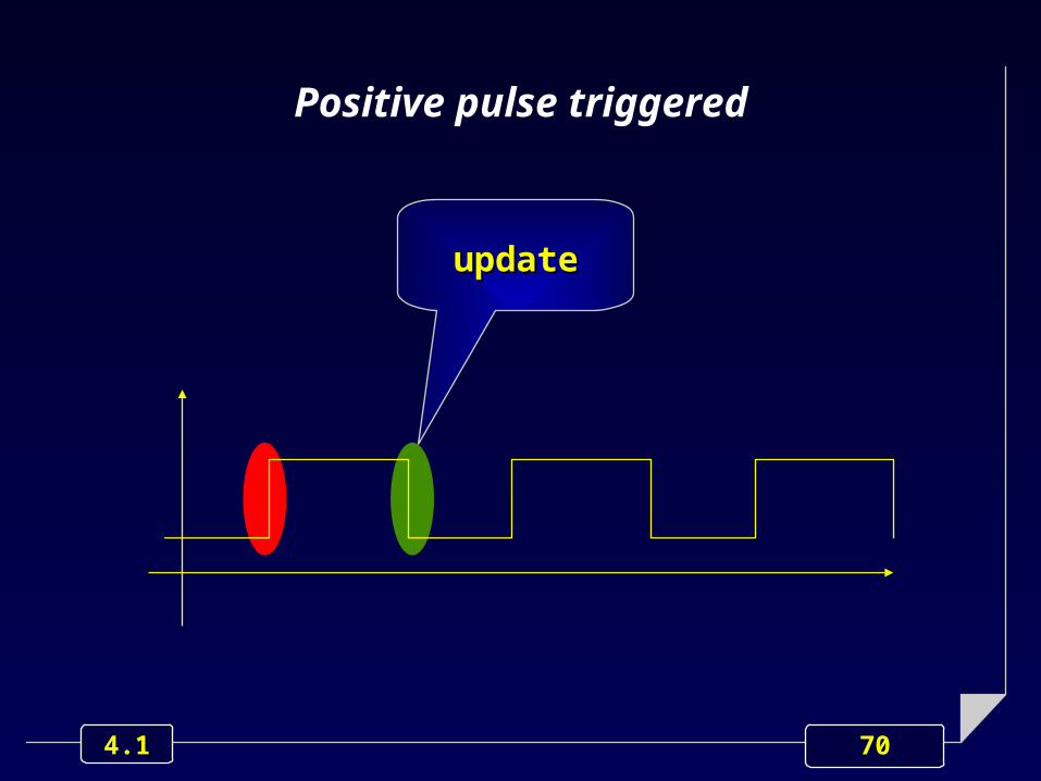
70 4.1
Positive pulse triggered
updateupdate

71 4.1
Positive pulse triggered

72 4.1
Positive pulse triggered
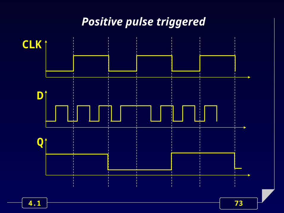
73 4.1
D
Q
Positive pulse triggered
CLK

74 4.1
D
Q
Positive pulse triggered
CLK

75 4.1
D
Q
Positive pulse triggered
CLK

76 4.1
Graphical notation
Clock inputs are usually identify as follows:
Clock InputsClock Inputs

77 4.1
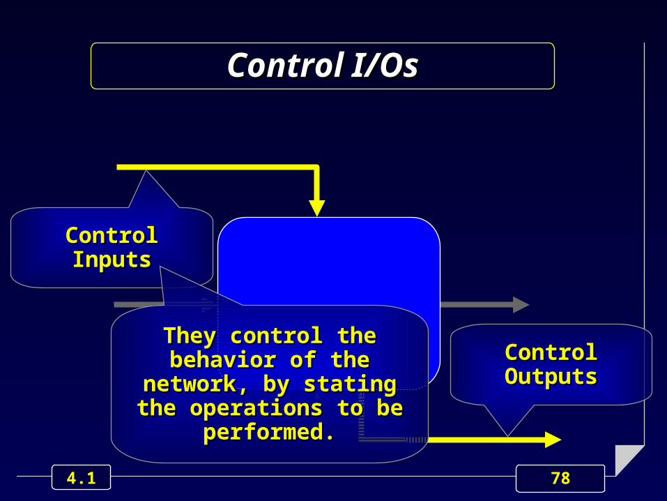
Control I/OsControl I/Os
Control InputsControl Inputs
Control OutputsControl Outputs
78 4.1
Control I/OsControl I/Os
Control InputsControl Inputs
Control OutputsControl OutputsThey control the behavior They control the behavior of the network, by stating of the network, by stating
the operations to be the operations to be performed.performed.

79 4.1
Control Inputs classification
According to their asserting characteristics, Control Inputs are usually classified as:
Synchronous
Asynchronous.

80 4.1
Control Inputs classification
According to their asserting characteristics, Control Inputs are usually classified as:
Synchronous
Asynchronous. When asserted, When asserted, they become active they become active
at the next clock at the next clock (edge or pulse), (edge or pulse),
onlyonly

81 4.1
Reset
Clock
Synchronous reset

82 4.1
Reset
Q
Clock
Synchronous reset
83 4.1
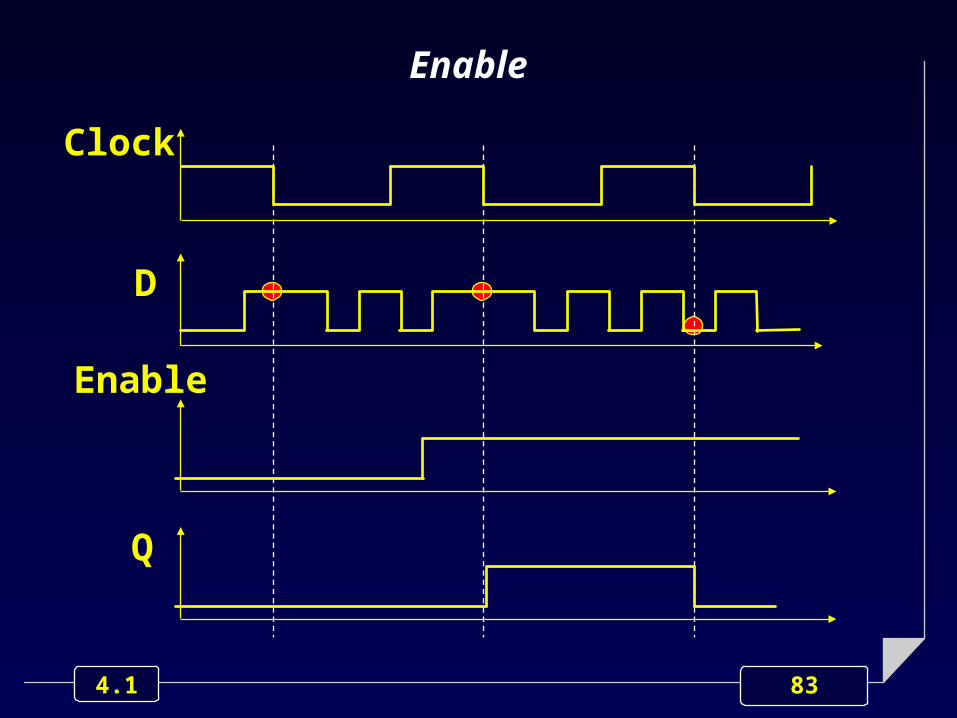
Clock
D
Enable
Q
Enable

84 4.1
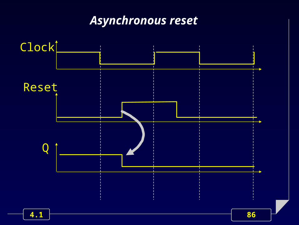
Control Inputs classification
According to their asserting characteristics, Control Inputs are usually classified as:
Synchronous
Asynchronous.
When asserted, they are immediately When asserted, they are immediately active, regardless the clock.active, regardless the clock.

85 4.1
Clock
Reset
Asynchronous reset
86 4.1
Clock
Reset
Q
Asynchronous reset

87 4.1