digital radiography artifacts - kansas … · digital radiography artifacts ... computed...
TRANSCRIPT

DIGITAL RADIOGRAPHY ARTIFACTS
WM TOD DROST, DAVID J. REESE, WILLIAM J. HORNOF
Radiographic artifacts may mimic a clinical feature, impair image quality, or obscure abnormalities. With the
development of digital radiography (DR), a new set of artifacts is introduced. Regardless of the technology, the
classic technical errors that occur with film screen radiography still occur using DR. Artifacts created using
computed radiography, DR, and incorrect image processing are discussed. Methods for correction of the
artifacts are presented. Veterinary Radiology & Ultrasound, Vol. 49, No. 1, Supp. 1, 2008, pp S48–S56.
Key words: computed radiography, digital radiography, image processing, radiographic image enhance-
ment, veterinary.
Introduction
RADIOGRAPHIC ARTIFACTS ARE portions of the image
that may mimic a clinical feature, impair image qual-
ity, or obscure abnormalities.1,2 With the development of
digital radiography (DR), a new set of artifacts is intro-
duced. In this article, we will discuss some of the more
common artifacts encountered with the two general cate-
gories of digital radiographic systems, computed radiogra-
phy (CR), which uses a photosensitive phosphor sheet to
record the latent image, and DR, which produces a digital
radiograph without the need for a manual processing step.
DR systems can be further divided into a charge-coupled
device (CCD), which uses a scintillating sheet to produce
light photons in response to radiation exposure, and a
camera and lens system to record the image, and a flat panel
DR, which either converts radiation exposure into electric
charge which is then digitized (Direct DR) or uses a scin-
tillating layer to generate light photons and then digitizes
the emitted light (Indirect DR).3 For more information
about DR equipment, see the article in this Supplement.4
Regardless of the technology, the classic technical errors
that occur with film screen radiography still occur when
using DR.2,5 Appropriate radiographic techniques must be
used. Malpositioning, patient motion, incorrect patient
identification, and double exposures can all still occur.1,2,5
One of the biggest image quality advantages of DR is the
linear response to radiation exposure, resulting in a wider
dynamic range compared with film/screen radiography.
Using a film/screen system, the response of the film
to radiation exposure is sigmoid shaped with a relatively
narrow range of X-ray exposure, creating a quality radio-
graph. At the low end of the sigmoid curve, film/screen
systems do not record low levels of radiation exposure and
the resultant film is white or clear. At the high end of the
sigmoid curve, the resultant film is black and overexposed.
Increasing the amount of radiation exposure to a film/
screen system at the high end of the sigmoid curve will not
result in a blacker radiograph. DR systems are much
more forgiving of exposure errors than film/screen systems
(Fig. 1).6,7
Look-Up Table (LUT) Errors
Radiographs are typically viewed by backlighting on a
viewbox. Chemical processes make film blacker as expo-
sure increases. Film/screen systems typically respond over
about a 20-fold change in X-ray exposure. In other words,
the minimum amount of exposure it takes to make the film
change is about 1/20 the amount it takes to make the film
totally black and unresponsive to further increases in ex-
posure. Thus, it is all but impossible to adequately expose a
lateral view of a large dog pelvis positioned with the legs
separated and still visualize the soft tissues surrounding
one of the stifles. Conversely, a proper exposure of the
lateral stifle will underexpose the pelvis. With film/screen
systems, two separate radiographs must be made at differ-
ent exposures to evaluate both the stifle and the pelvis. The
dynamic range of film/screen is just too narrow to accom-
modate such a wide range of exposures.
Digital systems (both CR and DR) have a much wider
dynamic range and remain linear up to a 10,000-fold
change in exposure. CCD systems usually have a slightly
narrower dynamic range than CR or DR because of veiling
glare in the lens system, but still exceed the dynamic range
of film/screen. Thus, a digital detector used to acquire a
Address correspondence and reprint requests to Wm Tod Drost, at theabove address.
Dr. Reese’s present address is, Department of Veterinary Clinical Sci-ences, The Ohio State University, 601 Vernon L. Tharp Street, Columbus,OH, 43210.
doi: 10.1111/j.1740-8261.2007.00334.x
From the Department of Veterinary Clinical Sciences, The Ohio StateUniversity, 601 Vernon L. Tharp Street, Columbus, OH 43210 (Drost);the Department of Small Animal Clinical Sciences, University of Florida,Gainesville, FL 32612 (Reese); and Eklin Medical Systems, 1605 WyattDr., Santa Clara, CA 95054 (Hornof).
S48

single lateral radiograph of the above-mentioned patient
will have accurately recorded both the pelvis and the stifle.
The problem that arises now is how to display such a wide
range of exposure for viewing.
Radiographs are displayed by backlighting rather than
printing them on paper and viewing with reflected light,
because a backlit radiograph has a much wider dynamic
range of brightness than printed paper (or a computer
monitor). However, as stated, even the relatively wide dis-
play range of blackness on a backlit radiograph is incapa-
ble of showing us both the stifle and the pelvis on a single
view. So, how then can we take advantage of the wide
dynamic range of digital systems? With the radiograph
(film), we use a bright light on the stifle to enhance visu-
alization of the stifle. With digital images, we use the
LUT. The LUT determines how bright individual pixel
values will be displayed. The LUT is basically a curve that
maps pixel values to monitor brightness. If that curve
matches the response of a film/screen system to X-ray
exposure, it will look exactly like a radiograph. Thus,
a digital radiograph that is too light or too dark needs
an adjustment in the LUT but not in the radiographic
technique.
The raw data of a digital acquisition is typically 12–14
bits, but after the LUT is applied during preprocessing,
most systems discard those bits beyond the display range
and save only 10–12 bits for viewing and storage. Thus,
application of the LUT in the preprocessing phase is po-
tentially destructive and information can be lost. This loss
is typically manifest as clipping. Digital display programs
also provide the user tools to interactively adjust the LUT
once it is received from the modality. These are usually
Fig. 1. Three digital radiographs of a frozen cadaver equine carpus taken at 80kVp and 0.3mAs (A), 1.5mAs (B), and 10.0mAs (C). At this displayresolution the three radiographs are identical. (Images courtesy of Dr. Sarah Puchalski)
Fig. 2. Lateral radiograph of a dog’s tibia with look-up table appliedduring the acquistion that caused clipping. (A) The image as presented to theviewing software. (B) After the radiograph is rewindowed using the displaysoftware. It is obvious the soft tissues were clipped and are no longer avail-able.
S49DIGITAL RADIOGRAPHYARTIFACTSVol. 49, No. 1, Supplement 1

called window and level or contrast and brightness, re-
spectively. Window/contrast determines the range of pixel
values that will be displayed and level/brightness deter-
mines where that range is centered over the entire range of
recoded exposures. However, if the image has been clipped
in the preprocessing step, no amount of adjustment by the
display software can retrieve it (Fig. 2).
Image Processing Errors
Digital image processing is described in more detail in
this supplement,8 but some of the common artifacts caused
by image processing are discussed here. As stated previ-
ously, the wide dynamic range attainable with digital X-ray
detectors far exceeds that attainable with film/screen. Un-
Fig. 3. Lateral radiograph of a large dog’s pelvis made to include the coxofemoral joints, stifle and tail. (A) Image displayed using a relatively flat look-uptable (LUT). All thicknesses of structures are visible, including the thin tail and stifle and the thicker pelvis, but at very low and unacceptable contrast. (B)Images displayed using a steeper LUT centered on the pelvis. The pelvis now has high contrast, but the thinner stifle and tail are not visible. (C) The LUT usedin B is now centered on the tail and stifle. These structures become visible with high contrast, but the pelvis and abdomen are no longer visible. (D) Imageprocessing can be used to decrease the difference between the pixel values beneath the stifle and tail compared with the pelvis, allowing all structures to bedisplayed with a single LUT. By applying image processing before assigning the LUT, all the anatomic structures included in the radiograph are visible withhigh contrast.
S50 DROST, REESE, AND HORNOF 2008

fortunately, the relatively narrow dynamic range of both
film and computer monitors does not allow us to perceive
such a wide range of exposures in a diagnostically useful
manner. With film/screen, it is typical that a properly ex-
posed radiograph of the pelvis cannot be used effectively to
evaluate the stifle, often even with a bright light.
Using a digital system, to solve the dilemma of seeing
both the stifle and the pelvis on a single exposure, we would
need to use two different LUTs, one for the stifle that
would leave the pelvis white, and one for the pelvis that
would leave the stifle black. We do not need to repeat the
radiograph because we can adjust the LUT (Fig. 3). But, it
would be nice to view all the anatomic areas in the image at
once. This can be done, but it requires image processing.
Image processing involves mathematical manipulation of
the image to minimize the overall range of displayed pixel
values, while maintaining high contrast. In its simplest form
this involves a process called unsharp masking. This is ac-
complished by making a copy of the original radiograph,
blurring it, and then subtracting it from the original. Using
the example of the lateral view of the pelvis described
above, in the blurred image, the bones will not be visible
because of the blurring, but we now have an image that is
black over the area of the stifle (high pixel values) (Fig. 3B)
and white over the area of the pelvis (low pixel values) (Fig.
3C). When these two are subtracted, the stifle and pelvis
now have pixel values that are much closer to each other,
while the bones (edges) have been preserved. This accom-
plishes the goal of making all structures visible with a single
LUT (Fig. 3D). What we are attempting to accomplish is to
Fig. 5. Uncropped, digital radiograph windowed on the portion of theradiograph outside the collimator. With film/screen systems, the portions ofthe radiograph outside the primary beam are typically white, leaving somestaff cavalier about wearing protective gloves. The high sensitivity of a digitalsystem allows clear visibility of the bones of this staff person’s unprotectedfingers. (Note: This image was not created at the authors’ institutions.)
Fig. 6. Three digital radiographs of a frozen cadaver equine carpus taken at 80kVp and 0.3mAs (A), 1.5mAs (B), and 10.0mAs (C) as seen in Fig. 1. At thisdisplay size the mottle in A is visible, with improvement in detail in (B) and (C). (Images courtesy of Dr. Sarah Puchalski)
Fig. 4. Cropped, lateral radiograph of a dog’s stifle after tibial plateauleveling osteotomy (TPLO) surgery that has had unsharp masking applied toimprove the display. (A) Black halos (black arrows) are present around thedistal part of a bone screw and a femoral condyle. This black halo is knownas Uberschwinger or rebound effect. (B) Cropped, lateral radiograph of adog’s stifle after TPLO surgery that has had multifrequency processing ap-plied to improve the display. No black halos are noted.
S51DIGITAL RADIOGRAPHYARTIFACTSVol. 49, No. 1, Supplement 1

remove the overall exposure differences between the stifle
and the pelvis, but we do not want to alter anatomic detail.
By blurring the image we only approximate this. When we
approach edges like a bone/soft-tissue interface, the blur-
ring function averages pixel values. Thus, the values along
edges in the blurred image are not real. When the images
are subtracted, they cause edge enhancement and the halo
or the Uberschwinger artifact. Edge enhancement makes
radiographs look pretty, with high contrast and edge defi-
nition, but it also destroys fine detail along sharp edges like
metal implants, and accentuates noise. These negative
effects are generally not visible from far, but during close
inspection, as you would do in a diagnostic situation, one
can reveal the halo or the Uberschwinger artifact around
implants that can be mistaken for bone loss, and the ob-
jectionable effects of noise (Fig. 4).
Uberschwinger or a rebound effect appears as a radio-
lucent halo around metal or areas where there is a large
density difference between adjacent objects (Fig. 4).5,9,10 It
results from the frequency processing induced by the un-
sharp masking that determines the degree of edge enhance-
ment in the final image.7,10 Uberschwinger may simulate
loosening of orthopedic devices or mimic pneumothorax.
To suppress the Uberschwinger artifact algorithms have
been developed that effectively allow control of the entire
frequency spectrum of the image. Without a lengthy or
mathematical explanation, this process essentially decom-
poses the image into frequency bands including the higher
frequency components (sharp edges and noise) and lower
frequency components (overall density). The low-frequency
components can then be removed and the image reassem-
bled with minimal Uberschwinger artifact or noise en-
hancement.
Exposure Artifacts
When the receiver does not get enough X-ray input the
resultant image is grainy, noisy, mottled, and pixilated,2,5,11
but because the LUT can be adjusted, the radiograph ap-
pears properly exposed. Because DR systems are more
sensitive to radiation and have a wide dynamic range, se-
vere underexposure using a DR system can result in an
image, whereas using the same patient and radiographic
technique on a film/screen system, an image of the
patient would not even be visible. In Fig. 5, images are
seen (when rewindowed) outside the collimated portion of
the radiograph. In this case a breach in radiation safety
was uncovered. It is tempting to interpret the underexposed
portion of the radiograph because rewindowing makes
that portion of the image more obvious. However, subtle
radiographic findings may not be apparent in underex-
posed digital radiographs.7 The graininess or pixilation
(Fig. 6) observed in underexposed digital radiographs
comes from statistical uncertainty in adjacent pixels.
This is analogous to scintigraphy where, the more counts
per pixel, the better the image quality.12,13 Display size
affects the appearance of a radiograph. If the display size
of an underexposed radiograph is minimized, the result is
several of the pixels in the original radiograph are now
averaged in a single-display pixel. When the uncertainty of
adjacent pixels is minimized by making the displayed
size smaller, the radiograph appears much sharper.
Conversely, if a slightly underexposed digital radiograph
is zoomed to view individual pixels and compared with a
properly exposed radiograph, the underexposed radio-
graph is objectionably noisy (Fig. 6). With a given film/
screen system, there is a relationship between dose and
detail. In general, high-detail systems require more dose
than high-speed systems, and a system must be chosen for
the study at hand. A high-speed system would typically
be used for surveying abdomens, whereas a high-detail
system would be used for surveying the spine of the same
patient. With digital systems the same principle applies.
Lower radiation exposure can be used for survey radio-
graphs, but when more anatomic detail is needed, a higher
dose is required.
Fig. 7. Two radiographs of a canine lumbar spine acquired from a flat panel detector system. (A) This radiograph is overexposed to the point of saturationof the detector. The midabdominal organs are not seen and the soft tissues dorsal to the spine are completely black. With this degree of overexposure, thecalibration mask is visible, revealing the plank-like arrangement of the flat panel detector system. (B) A properly exposed lateral radiograph of the lumbar spineof the same dog in A.
S52 DROST, REESE, AND HORNOF 2008

On the opposite end of the spectrum, the wide dynamic
range of digital systems permits using more photons than
the minimum necessary to acquire an acceptable radio-
graph for a given study. However, even with the wide dy-
namic range of digital systems, eventually, the detector
system will saturate or reach a state where it can no longer
respond to additional dose. When this happens, each pixel
in the overexposed area has been set to its maximum value,
and the margins of structures, especially thin structures, are
no longer viewable, even when one tries to rewindow the
images (Fig. 7A).11 With CR systems, the saturated areas
appear uniform, but some DR systems use a calibration
mask to correct for nonuniformity in the detector, and with
all pixels set to the same maximum value, the mask be-
comes visible. Each DR system that uses a calibration
mask will typically have a characteristic pattern in the
mask depending upon the construction of the panel. In
some DR systems, planking or linear striations can appear
in the background (Fig. 7A).5 To correct this artifact, the
animal must be reradiographed using a lower exposure
(Fig. 7B).
Calibration Mask Errors
If a uniform X-ray source is applied to a digital detector,
the response of each pixel should be identical. However, an
X-ray field is not uniform because of the heel effect and
inverse square law. By acquiring a flood field with a DR
detector and creating a calibration mask, the sensitivity of
each pixel can be set identically. This is similar to calibra-
tion masks created to correct for g camera uniformity and
linearity.14 Using DR, the display pixel is precisely
matched with the detector. The DR detector is typically
mounted in the table such that the orientation of the panel
is fixed relative to the tube. This process creates an excep-
Fig. 8. Creating a calibration mask error. (A) A piece of electrical tape was placed on the X-ray table. The calibration mask was created with the electricaltape in place. (B) A flood-field radiograph was made without moving the X-ray table after calibration. No artifact is present because the calibration masksuccessfully compensated for the tape. (C.) The X-ray table was moved to the right and a second flood-field radiograph was made. A pair of black and whiteimages of the tape are now visible. The black image is the correction made by the calibration mask and the white image is the actual piece of tape.
Fig. 9. A radiograph made using a flat-panel detector system that hadbeen calibrated with a small spot of contrast medium on the collimator face.The dark artifact (arrow) on the cranial endplate of L2 was caused by thisspot being burned into the calibration mask. The indistinct borders of thedark artifact meant the offending object was not on the detector panel.Cleaning the collimator face and recalibrating the detector panel correctedthe problem.
Fig. 10. An example of radiofrequency (RF) interference (between thewhite arrows) caused by a breakdown in RF shielding in a flat-panel digitalradiography system. Artifacts from RF interference can take many formsbut typically generate a repeatable pattern in the radiograph.
S53DIGITAL RADIOGRAPHYARTIFACTSVol. 49, No. 1, Supplement 1

tionally uniform image that compensates for heel effect and
inverse square law. Using CR, this approach cannot be
used because the imaging plate is separate from the detec-
tor. Each pixel of the display does not map exactly to a
pixel-sized area of the CR phosphor sheet. Thus, CR sys-
tems must be designed with incredible precision to make
travel of the detector through the scanning process as uni-
form and reproducible as possible. If one of the phosphor
sheets is scratched or damaged there is no way to correct
for it. Because the orientation of the CR cassette relative to
the X-ray beam cannot be assured, this cannot be corrected
by creating a correction matrix. CCD systems are fixed in
the table and have a close match between the detector and
display pixels, but because of the distance between the
scintillator and the camera, slight changes in temperature
can result in shifting.
Interesting artifacts occur if there is anything in the
X-ray beam during the calibration process. To our knowl-
edge, systematic characterization of calibration mask arti-
facts for DR systems is not reported. What are presented
here are our own observations.
The calibration procedure typically requires a set of ra-
diographs to be acquired, with the detector entirely flooded
with the X-ray beam. If any object is in the X-ray beam
during the calibration process, or if the X-ray beam does
not reach the outside margins of the detector, it will be
burned into the mask. If during the calibration procedure
there is an object in the beam that is not fixed in position
relative to the panel, when the object is moved, a pair of
artifacts will appear (Fig. 8). One will be a negative image
of the object from the mask and appears dark, whereas the
other will be a radiograph of the object itself and appears
lighter than the background. To illustrate this principle, a
flat-panel DR system was calibrated with a piece of elec-
trical tape stuck on the X-ray table (Fig. 8A). A flood-field
radiograph was made without moving the X-ray table after
calibration (Fig. 8B). No artifact was present, because the
calibration mask successfully compensated for the tape. A
second radiograph was made after moving the X-ray table
slightly and it produced a paired black and white image of
the tape (Fig. 8C). The contrast resolution of digital sys-
tems far exceeds that of film/screen systems, and in clinical
situations artifacts from such things as the paint used for
the crosshairs on the collimator window may show up with
radiographs of small patients.
Inhomogeneous tabletops may produce stipple that was
not visible using film/screen. In this situation if the tabletop
cannot be replaced, the calibration procedure should either
be performed with the detector on top of the table, or the
table should be moved between each of the calibration ex-
posures. If the panel is calibrated without moving the table
between exposures, the pattern in the table will be burned
into the mask and subsequent radiographs acquired after
moving the table will have the additive effect of the neg-
ative mask image of the tabletop stipple added to the ra-
diograph of the stipple in the new location.
Occasionally, the cause of calibration mask artifacts can
be difficult to locate, but the key is recognizing the artifact
as a paired black and white structure. Particularly frus-
trating are intermittent artifacts, like something loose in-
side the collimator. Virtually invisible iodinated contrast
medium splashed on the collimator window can be difficult
to detect, but the key to recognizing collimator contam-
ination is that the artifacts are blurry because of penumbra
(Fig. 9) whereas tabletop or debris on the panel itself are
sharp.
DR systems are susceptible to radiofrequency (RF) in-
terference. Generally, the detectors are shielded against RF
interference, but if the detector is placed in close proximity
to an RF source, like some automatic exposure control
detectors, or if there is a break in the shielding of the de-
tector of cables, artifacts can result (Fig. 10). In general,
RF-interference artifacts have a periodic pattern, which is
characteristic for the cause. RF interference can be prob-
lematic as it may be intermittent, and with portable units,
may only occur in certain locations or with the detector in
certain positions.
Ghost Images
DR systems can produce ghost images. Ghost images
are analogous to the ghost images produced by certain
film/screen systems because of afterglow in the scintillating
screen. Once the fluorescent screen is stimulated, light is
Fig. 11. Ghost image of the lead L marker adjacent to the equine patellafrom a flat-panel digital radiography system. A radiograph with an L markerin the noncollimated portion of the X-ray beam was made seconds beforethis image was made. The ghost L occurs because the photodiodes aroundthe marker record a very high radiation dose relative to the photodiodesbeneath the marker. For a short period of time after the first exposure, thelevel of charge retained by the photodiodes differs between the two areas.When the subsequent exposure was made, negative images of the L markerappeared.
S54 DROST, REESE, AND HORNOF 2008
emitted, but the intensity of light emission decreases with
time. If the cassette is immediately processed and reloaded
with fresh film, the afterglow from the previous exposure
can be burned into the film before the next exposure.
Effectively, this same thing can happen with DR systems,
particularly those with photodiodes. Typically, the light
emitted by the scintillating layer is digitized by the photo-
diodes and a radiograph is created. However, stimulated
photodiodes trap charge, and release of that charge can
persist after the readout.15 This occurrence is illustrated in
an equine stifle examination, where high exposure is used
and a lead marker is placed on the detector outside the
contour of the patient. The photodiodes around the marker
receive a very high radiation exposure, whereas the pho-
todiodes beneath the marker receive little exposure. For a
short period of time after the exposure, the level of charge
retained by the photodiodes differs between the two
areas.15 If a subsequent exposure is made quickly, it will
then show a negative image of the lead marker (Fig. 11).
CR Artifacts
Double exposures occur when two exposures are made
using the same cassette without erasing the plate in be-
tween. The wide dynamic range of CR allows two similar-
density images to be viewed at the same time. Compared
with film/screen systems, a double exposure is not darker
than a single exposure.7 Double exposures are created if a
CR plate is not completely erased by the automatic plate
reader.7,16 Ghost or memory artifacts (a.k.a., selenium
memory artifacts) occur when effective saturation of the
image receptor is present.17 Radiation can be trapped for
several minutes in the plate. One must ensure that the cor-
rect erasure setting is employed. If the cassette has not been
used for a while, it should be erased before use.1,6 This
generally leads to fogging artifacts vs. ghost artifacts.16
Correcting double-exposure artifacts requires reradio-
graphing the patient.
Improper LUT assignment often leads to artifacts. The
goal of LUT assignment is to maximize the contrast in the
specific part of the image that is of interest.2 LUT-assign-
ment errors can lead to alterations in image contrast and
density.7 If the wrong region of interest is selected, the
whole image will be incorrectly displayed. Understanding
how a CR plate reader works is important for understand-
ing alterations in image contrast and density. Using an
automatic setting, a high speed, low-intensity laser initially
scans the entire plate.6,7 From this initial scan, a histogram
is generated to characterize how the energy is displayed
across this plate. Based on the histogram, density and
contrast parameters are automatically set and these pa-
rameters are then used in the final (second) reading of the
image plate. Using a semi-automatic method for scanning
a plate, the user selects a region of interest that the plate
reader will then scan and use for histogram analysis.6,7
With the semi-automatic mode, if a person selects the
wrong region of interest, the histogram generated will not
represent the proper region. In the automatic mode, the
degree of collimation6 and the type of material in the image
(such as metal) may affect the histogram that is initially
generated. For instance, on a thoracic radiograph, if one
chooses a region of interest over the heart vs. a region of
interest over the lungs, two different images will be pro-
duced. Alternatively, if the user selects the wrong body area
or incorrect diagnostic specifier (e.g., thorax vs. musculo-
skeletal) before the image is made, then the plate reader
will set up a different type of histogram.16 For example, if
an abdomen algorithm is initially chosen, the thorax is
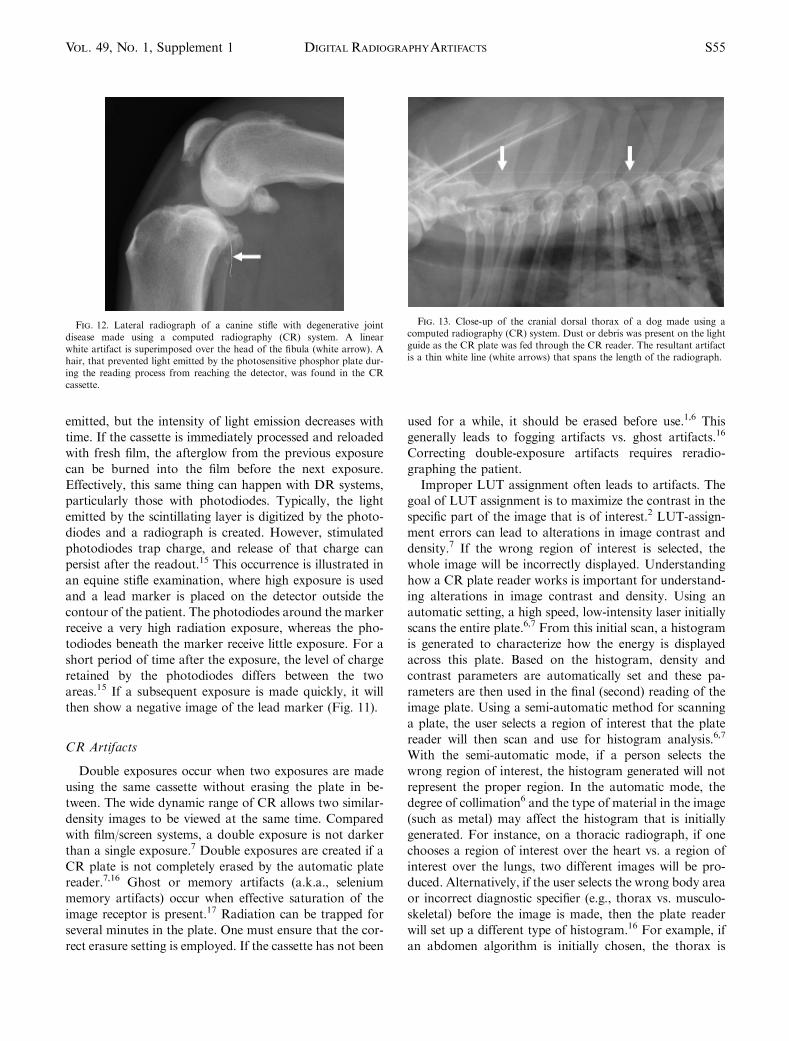
Fig. 12. Lateral radiograph of a canine stifle with degenerative jointdisease made using a computed radiography (CR) system. A linearwhite artifact is superimposed over the head of the fibula (white arrow). Ahair, that prevented light emitted by the photosensitive phosphor plate dur-ing the reading process from reaching the detector, was found in the CRcassette.
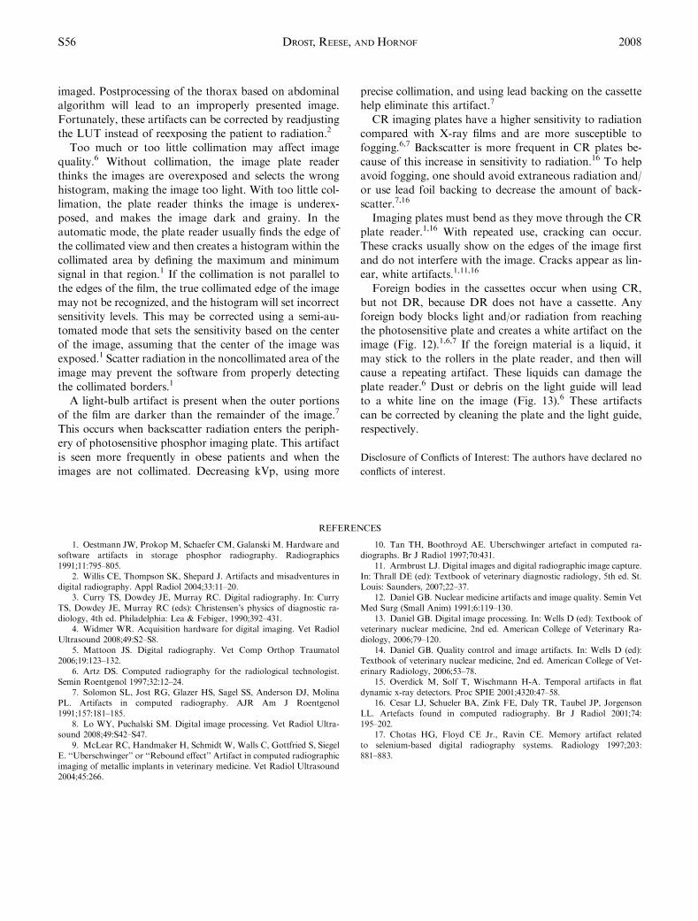
Fig. 13. Close-up of the cranial dorsal thorax of a dog made using acomputed radiography (CR) system. Dust or debris was present on the lightguide as the CR plate was fed through the CR reader. The resultant artifactis a thin white line (white arrows) that spans the length of the radiograph.
S55DIGITAL RADIOGRAPHYARTIFACTSVol. 49, No. 1, Supplement 1
imaged. Postprocessing of the thorax based on abdominal
algorithm will lead to an improperly presented image.
Fortunately, these artifacts can be corrected by readjusting
the LUT instead of reexposing the patient to radiation.2
Too much or too little collimation may affect image
quality.6 Without collimation, the image plate reader
thinks the images are overexposed and selects the wrong
histogram, making the image too light. With too little col-
limation, the plate reader thinks the image is underex-
posed, and makes the image dark and grainy. In the
automatic mode, the plate reader usually finds the edge of
the collimated view and then creates a histogram within the
collimated area by defining the maximum and minimum
signal in that region.1 If the collimation is not parallel to
the edges of the film, the true collimated edge of the image
may not be recognized, and the histogram will set incorrect
sensitivity levels. This may be corrected using a semi-au-
tomated mode that sets the sensitivity based on the center
of the image, assuming that the center of the image was
exposed.1 Scatter radiation in the noncollimated area of the
image may prevent the software from properly detecting
the collimated borders.1
A light-bulb artifact is present when the outer portions
of the film are darker than the remainder of the image.7
This occurs when backscatter radiation enters the periph-
ery of photosensitive phosphor imaging plate. This artifact
is seen more frequently in obese patients and when the
images are not collimated. Decreasing kVp, using more
precise collimation, and using lead backing on the cassette
help eliminate this artifact.7
CR imaging plates have a higher sensitivity to radiation
compared with X-ray films and are more susceptible to
fogging.6,7 Backscatter is more frequent in CR plates be-
cause of this increase in sensitivity to radiation.16 To help
avoid fogging, one should avoid extraneous radiation and/
or use lead foil backing to decrease the amount of back-
scatter.7,16
Imaging plates must bend as they move through the CR
plate reader.1,16 With repeated use, cracking can occur.
These cracks usually show on the edges of the image first
and do not interfere with the image. Cracks appear as lin-
ear, white artifacts.1,11,16
Foreign bodies in the cassettes occur when using CR,
but not DR, because DR does not have a cassette. Any
foreign body blocks light and/or radiation from reaching
the photosensitive plate and creates a white artifact on the
image (Fig. 12).1,6,7 If the foreign material is a liquid, it
may stick to the rollers in the plate reader, and then will
cause a repeating artifact. These liquids can damage the
plate reader.6 Dust or debris on the light guide will lead
to a white line on the image (Fig. 13).6 These artifacts
can be corrected by cleaning the plate and the light guide,
respectively.
Disclosure of Conflicts of Interest: The authors have declared no
conflicts of interest.
REFERENCES
1. Oestmann JW, Prokop M, Schaefer CM, Galanski M. Hardware andsoftware artifacts in storage phosphor radiography. Radiographics1991;11:795–805.
2. Willis CE, Thompson SK, Shepard J. Artifacts and misadventures indigital radiography. Appl Radiol 2004;33:11–20.
3. Curry TS, Dowdey JE, Murray RC. Digital radiography. In: CurryTS, Dowdey JE, Murray RC (eds): Christensen’s physics of diagnostic ra-diology, 4th ed. Philadelphia: Lea & Febiger, 1990;392–431.
4. Widmer WR. Acquisition hardware for digital imaging. Vet RadiolUltrasound 2008;49:S2–S8.
5. Mattoon JS. Digital radiography. Vet Comp Orthop Traumatol2006;19:123–132.
6. Artz DS. Computed radiography for the radiological technologist.Semin Roentgenol 1997;32:12–24.
7. Solomon SL, Jost RG, Glazer HS, Sagel SS, Anderson DJ, MolinaPL. Artifacts in computed radiography. AJR Am J Roentgenol1991;157:181–185.
8. Lo WY, Puchalski SM. Digital image processing. Vet Radiol Ultra-sound 2008;49:S42–S47.
9. McLear RC, Handmaker H, Schmidt W, Walls C, Gottfried S, SiegelE. ‘‘Uberschwinger’’ or ‘‘Rebound effect’’ Artifact in computed radiographicimaging of metallic implants in veterinary medicine. Vet Radiol Ultrasound2004;45:266.
10. Tan TH, Boothroyd AE. Uberschwinger artefact in computed ra-diographs. Br J Radiol 1997;70:431.
11. Armbrust LJ. Digital images and digital radiographic image capture.In: Thrall DE (ed): Textbook of veterinary diagnostic radiology, 5th ed. St.Louis: Saunders, 2007;22–37.
12. Daniel GB. Nuclear medicine artifacts and image quality. Semin VetMed Surg (Small Anim) 1991;6:119–130.
13. Daniel GB. Digital image processing. In: Wells D (ed): Textbook ofveterinary nuclear medicine, 2nd ed. American College of Veterinary Ra-diology, 2006;79–120.
14. Daniel GB. Quality control and image artifacts. In: Wells D (ed):Textbook of veterinary nuclear medicine, 2nd ed. American College of Vet-erinary Radiology, 2006;53–78.
15. Overdick M, Solf T, Wischmann H-A. Temporal artifacts in flatdynamic x-ray detectors. Proc SPIE 2001;4320:47–58.
16. Cesar LJ, Schueler BA, Zink FE, Daly TR, Taubel JP, JorgensonLL. Artefacts found in computed radiography. Br J Radiol 2001;74:195–202.
17. Chotas HG, Floyd CE Jr., Ravin CE. Memory artifact relatedto selenium-based digital radiography systems. Radiology 1997;203:881–883.
S56 DROST, REESE, AND HORNOF 2008