digital radiography. basic concepts n image quality concepts –spatial resolution (limiting...
TRANSCRIPT

DigitalDigital RadiographyRadiography
Basic ConceptsBasic Concepts Image Quality ConceptsImage Quality Concepts
– Spatial Resolution (limiting resolution)Spatial Resolution (limiting resolution)– Noise: Quantum MottleNoise: Quantum Mottle
Nature of the Digital ImageNature of the Digital Image– Spatial DigitizationSpatial Digitization– Analog-to-Digital Conversion Analog-to-Digital Conversion
Digital Radiography FactorsDigital Radiography Factors– Spatial Digitization and ResolutionSpatial Digitization and Resolution– ADC and NoiseADC and Noise– ADC and Dynamic RangeADC and Dynamic Range
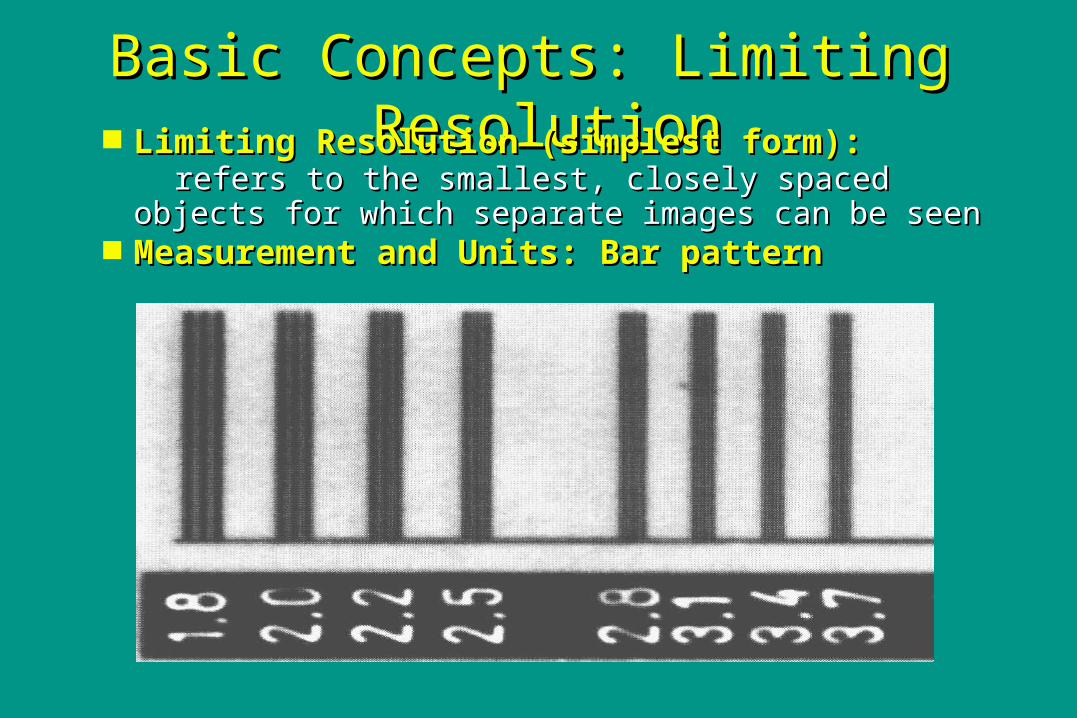
Basic Concepts: Limiting Basic Concepts: Limiting ResolutionResolution Limiting Resolution (simplest form):Limiting Resolution (simplest form):
refers to the smallest, closely spaced objects refers to the smallest, closely spaced objects for which separate images can be seenfor which separate images can be seen
Measurement and Units: Bar patternMeasurement and Units: Bar pattern

Basic Concepts: Limiting Basic Concepts: Limiting ResolutionResolution
Sources Blurring in radiography:Sources Blurring in radiography: – Focal spot (all types of radiography)Focal spot (all types of radiography)– Motion (all types of radiography)Motion (all types of radiography)– Receptor blur - depends on receptorReceptor blur - depends on receptor
Limiting Resolution (simplest Limiting Resolution (simplest form):form): Measurement and Units: Bar Measurement and Units: Bar pattern pattern Measured using bar pattern Measured using bar pattern (lead strips separated (lead strips separated by spaces) and by spaces) and expressed as smallest visible bar size expressed as smallest visible bar size or or highest spatial frequency (line-pairs/mm)highest spatial frequency (line-pairs/mm)
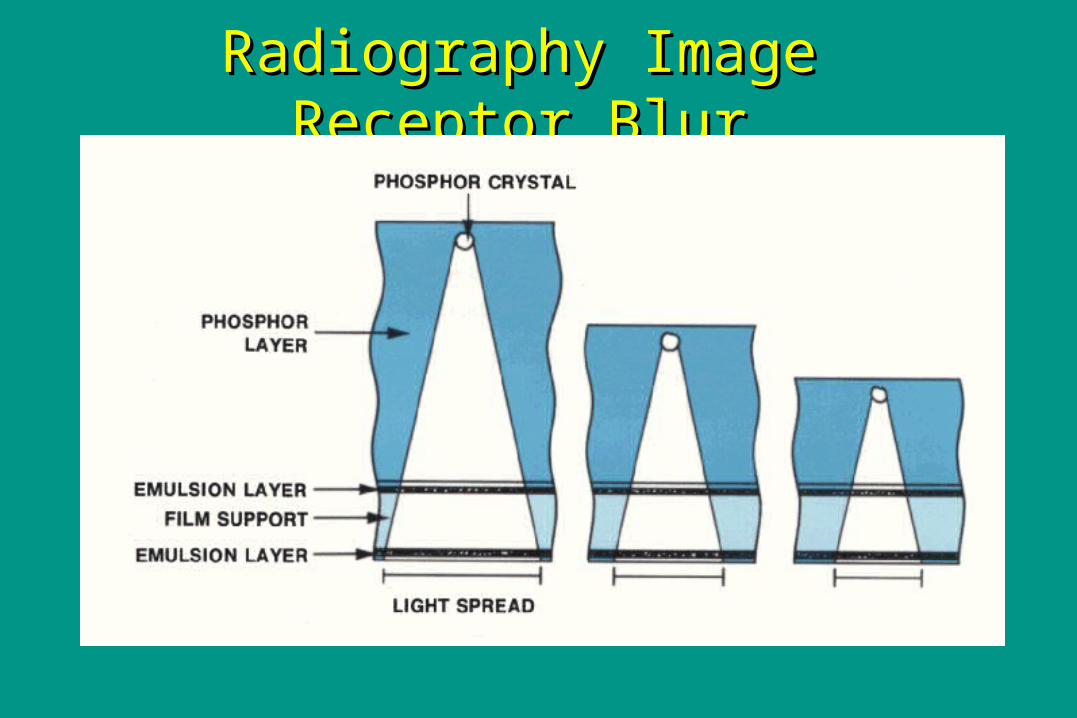
Radiography Image Receptor BlurRadiography Image Receptor Blur
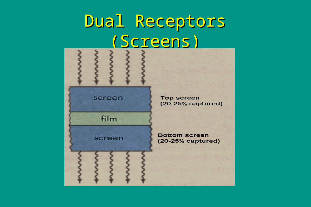
Dual Receptors (Screens)Dual Receptors (Screens)
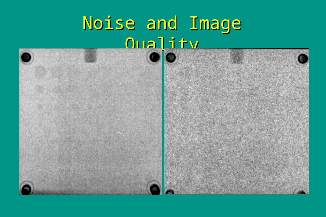
Noise and Image QualityNoise and Image Quality

Image Noise: Quantum mottleImage Noise: Quantum mottle Quantum mottle (QM) refers to the Quantum mottle (QM) refers to the
“graininess” of x-ray images“graininess” of x-ray images QM is caused by using a limited number QM is caused by using a limited number
of x-ray photons to make an imageof x-ray photons to make an image QM interferes with ability to detailsQM interferes with ability to details Using more photons (more mAs) Using more photons (more mAs)
reduces noise but increases radiation reduces noise but increases radiation exposureexposure

The Nature of the Digital ImageThe Nature of the Digital Image Basic Concepts: Resolution and NoiseBasic Concepts: Resolution and Noise The Digitization ProcessThe Digitization Process
– Spatial DigitizationSpatial Digitization– Analog-to-Digital Conversion (ADC)Analog-to-Digital Conversion (ADC)
Radiation Dose, Noise and ResolutionRadiation Dose, Noise and Resolution– Resolution versus Dose: receptor thicknessResolution versus Dose: receptor thickness– Dose versus Image Noise (Quantum Dose versus Image Noise (Quantum
mottle)mottle) Dynamic RangeDynamic Range

The Digitization ProcessThe Digitization Process Every “image” starts out in analog Every “image” starts out in analog
form:form:– ““light” image emitted by screenlight” image emitted by screen– ““light” image from intensifier output light” image from intensifier output
phosphorphosphor– TV camera voltagesTV camera voltages– Stimulated light from computed radiographyStimulated light from computed radiography
Analog “image” must be converted Analog “image” must be converted (digitized) to matrix of pixels stored (digitized) to matrix of pixels stored as binary numbersas binary numbers– Spatial digitization: generation of pixelsSpatial digitization: generation of pixels– Analog-to-Digital Conversion (ADC)Analog-to-Digital Conversion (ADC)

Spatial Digitization (pixels): SamplingSpatial Digitization (pixels): Sampling Must “measureMust “measure” ”
image along many image along many rows (512, 1024, etc) rows (512, 1024, etc) and at many point and at many point along each rowalong each row
Sampling done by:Sampling done by:– detector with discrete detector with discrete
“elements” (eg, CCD “elements” (eg, CCD camera, flat panel camera, flat panel detector) ordetector) or
– Raster scan processRaster scan process

Matrix Size, Resolution and BytesMatrix Size, Resolution and Bytes Regular Film/Screen: Regular Film/Screen: 5 line-pairs/mm 5 line-pairs/mm To “Equal” with Digital ImageTo “Equal” with Digital Image::
– 5 lp/mm = 10 pixels/mm (to see 5 bars+5 spaces)5 lp/mm = 10 pixels/mm (to see 5 bars+5 spaces)– 35 x 43 cm (14 x 17”) image = 350 x 430 mm35 x 43 cm (14 x 17”) image = 350 x 430 mm– 350 x 430 mm at 10 pixels/mm = 3500 x 4300 350 x 430 mm at 10 pixels/mm = 3500 x 4300
pixelspixels– 3500 x 4300 x 2 bytes/pixel (16 bits/pixel) = 30 3500 x 4300 x 2 bytes/pixel (16 bits/pixel) = 30
MBMB
Digital RadiographyDigital Radiography– Typically 2000 x 2500 pixels maximum (~3 lp/mm)Typically 2000 x 2500 pixels maximum (~3 lp/mm)

Digital Spatial ResolutionDigital Spatial Resolution

Spatial Digizitation: ADCSpatial Digizitation: ADC

ADC and Noise: How many bits? ADC and Noise: How many bits?

Contrast vs Latitude (Dyamic Range)Contrast vs Latitude (Dyamic Range)

ADC and Dynamic RangeADC and Dynamic Range Suppose we have:Suppose we have:
– 10 bit ADC: (1024 graylevels) 10 bit ADC: (1024 graylevels) – 1000:1 dynamic range (e.g. we can measure and 1000:1 dynamic range (e.g. we can measure and
record exposures from 1 mR to 1000 mR (1 R):record exposures from 1 mR to 1000 mR (1 R): Need 1 mR difference for different Need 1 mR difference for different
graylevelgraylevel– Differences between structures to see in image Differences between structures to see in image
may be < 1 mR in x-ray intensity reaching the may be < 1 mR in x-ray intensity reaching the receptorreceptor
Alternatives: Alternatives: – ““throw out” some dynamic range (limit range)throw out” some dynamic range (limit range)– Increase number of bits (still uncommon)Increase number of bits (still uncommon)

Digital DetectorsDigital Detectors Cassette-based: Image Storage Phosphor Cassette-based: Image Storage Phosphor
(CR)(CR) Image IntensifierImage Intensifier Scanned ProjectionScanned Projection Direct Digitizing (Full Field)Direct Digitizing (Full Field)
– CCD CameraCCD Camera– Selenium Flat Panel (“Direct” Digital Radiography)Selenium Flat Panel (“Direct” Digital Radiography)– Phosphor Flat Panel (“Indirect” Digital Phosphor Flat Panel (“Indirect” Digital
RadiographyRadiography))
Future TechnologyFuture Technology
Digital DetectorsDigital Detectors Cassette based Image Storage Phosphor Cassette based Image Storage Phosphor
(CR)(CR) Image IntensifierImage Intensifier Scanned ProjectionScanned Projection Direct Digitizing (Full Field)Direct Digitizing (Full Field)
– CCD CameraCCD Camera– Selenium Flat Panel (“Direct” Digital Radiography)Selenium Flat Panel (“Direct” Digital Radiography)– Phosphor Flat Panel (“Indirect” Digital Phosphor Flat Panel (“Indirect” Digital
RadiographyRadiography)) Future Technology Future Technology

CR Clinical UseCR Clinical Use


Conventional CR ScanningConventional CR Scanning

Flying Spot CR Flying Spot CR ScanScan
In a conventional In a conventional flying spot CR flying spot CR reader, stimulated reader, stimulated output exposure output exposure (scan level) from (scan level) from the IP is the IP is proportional to the proportional to the laser intensity I laser intensity I and dwell time Tand dwell time Tdd

Absorption EfficiencyAbsorption Efficiency

CR BlurCR Blur

Dynamic Range (Latitude)Dynamic Range (Latitude) Dynamic Range, or latitudeDynamic Range, or latitude refers the refers the
range of exposures which provide useful range of exposures which provide useful diagnostic information. For film, is the diagnostic information. For film, is the the range of exposures that provide the range of exposures that provide acceptable optical densities (ie, not too acceptable optical densities (ie, not too dark and not too light)dark and not too light)

Dynamic RangeDynamic Range
0
0.5
1
1.5
2
2.5
3
3.5
LG
M o
r O
D
0 0.30.60.91.21.51.82.12.42.7 3 3.33.63.94.24.54.8Log Relative Exposure (Log (Ei/Eo)
LGM and OD vs ExposureAgfa CR vs Lanex Reg
CR-200
Lanex Reg

Dynamic Range (Latitude) CR vs Film Dynamic Range (Latitude) CR vs Film
Regular F/S:Regular F/S: 16:116:1 (between 0.5 and 2.5 (between 0.5 and 2.5 OD) (exposure yielding 2.5 OD is 16x OD) (exposure yielding 2.5 OD is 16x exposure yielding 0.5 OD)exposure yielding 0.5 OD)
CR:CR: >>10,000:110,000:1 (between minimum and (between minimum and maximum measurable scan levels)maximum measurable scan levels)
Dynamic Range (latitude):Dynamic Range (latitude): range of range of exposures exposures providing providing useful diagnostic informationuseful diagnostic information
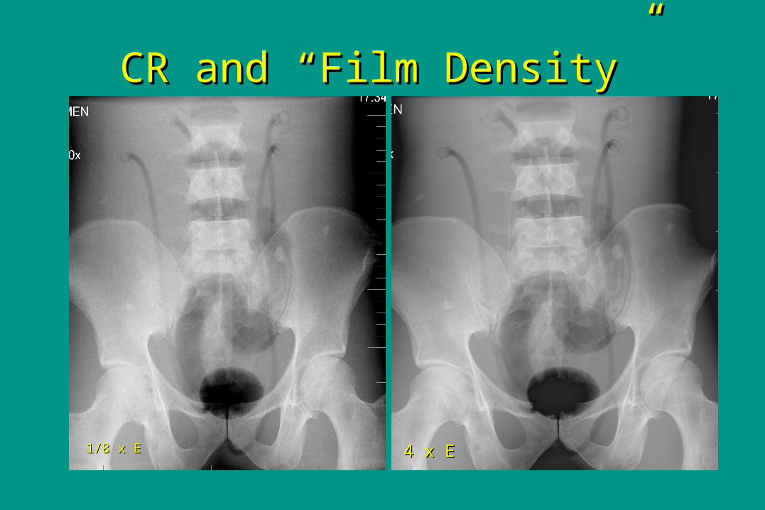
CR and “Film Density”CR and “Film Density”
4 x E4 x E1/8 x E1/8 x E

Radiation Dose with DRRadiation Dose with DR How much is enough ?How much is enough ?
– Image Noise (Quantum mottle)Image Noise (Quantum mottle)– required image qualityrequired image quality
How much is too much?How much is too much?– Patient radiation exposure concernsPatient radiation exposure concerns– possible saturation of parts of image (all possible saturation of parts of image (all
black)black)
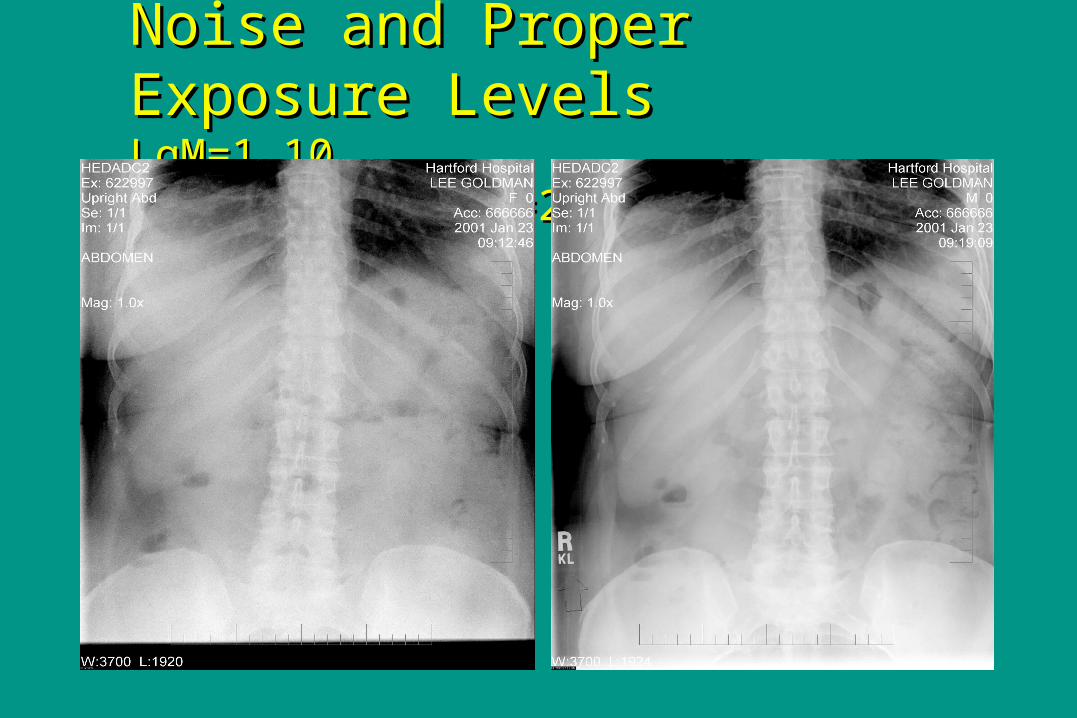
Noise and Proper Exposure LevelsNoise and Proper Exposure LevelsLgM=1.10 LgM=2.1LgM=1.10 LgM=2.1
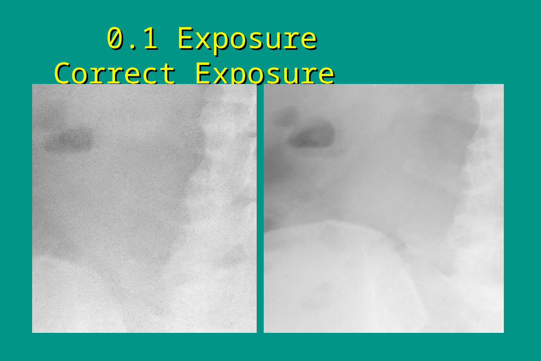
0.1 Exposure0.1 Exposure Correct Exposure Correct Exposure
FUTURE CR TECHNOLOGYFUTURE CR TECHNOLOGY New phosphors and scan head New phosphors and scan head
technologytechnology Dual EnergyDual Energy

““Flat Panel” CR Receptor DevicesFlat Panel” CR Receptor Devices


Dual Energy ImagingDual Energy Imaging