digital signal processing techniques - dimtel · pdf fileintroduction signal synthesis up- and...
TRANSCRIPT

Introduction Signal synthesis Up- and Down-conversion Signal Blocks
Digital Signal Processing Techniques
Dmitry Teytelman
Dimtel, Inc., San Jose, CA, 95124, USA
June 17, 2009

Introduction Signal synthesis Up- and Down-conversion Signal Blocks
Outline
1 Introduction
2 Signal synthesisArbitrary Waveform GenerationCORDICDirect Digital Synthesis
3 Up- and Down-conversionI&Q ProcessingFrequency Conversion
4 Signal BlocksPhase Shifting

Introduction Signal synthesis Up- and Down-conversion Signal Blocks
Linear and Non-linear DSP
Yesterday we talked mostly about linear signal processing— filtering.
Of course sampling and quantization is non-linear;Sampling rate change (decimation).
Many more exciting non-linear things to do.
Introduction Signal synthesis Up- and Down-conversion Signal Blocks
Linear and Non-linear DSP
Yesterday we talked mostly about linear signal processing— filtering.
Of course sampling and quantization is non-linear;Sampling rate change (decimation).
Many more exciting non-linear things to do.
Introduction Signal synthesis Up- and Down-conversion Signal Blocks
Linear and Non-linear DSP
Yesterday we talked mostly about linear signal processing— filtering.
Of course sampling and quantization is non-linear;Sampling rate change (decimation).
Many more exciting non-linear things to do.

Introduction Signal synthesis Up- and Down-conversion Signal Blocks
Problem Partitioning
When you do real-time signal processing, problempartitioning is critical.DSP complexity scale.Push floating point elaborate algorithms to a CPU, not inreal time.Project the problem into a set of coefficient setpoints,controlling real-time hardware.
Introduction Signal synthesis Up- and Down-conversion Signal Blocks
Non-linear Methods
Signal synthesis.Downconversion.Upconversion.Sampling rate changes: decimation and upsampling.Quadratic functions.Trigonometric functions.
Introduction Signal synthesis Up- and Down-conversion Signal Blocks
Non-linear Methods
Signal synthesis.Downconversion.Upconversion.Sampling rate changes: decimation and upsampling.Quadratic functions.Trigonometric functions.
Introduction Signal synthesis Up- and Down-conversion Signal Blocks
Non-linear Methods
Signal synthesis.Downconversion.Upconversion.Sampling rate changes: decimation and upsampling.Quadratic functions.Trigonometric functions.
Introduction Signal synthesis Up- and Down-conversion Signal Blocks
Non-linear Methods
Signal synthesis.Downconversion.Upconversion.Sampling rate changes: decimation and upsampling.Quadratic functions.Trigonometric functions.
Introduction Signal synthesis Up- and Down-conversion Signal Blocks
Non-linear Methods
Signal synthesis.Downconversion.Upconversion.Sampling rate changes: decimation and upsampling.Quadratic functions.Trigonometric functions.
Introduction Signal synthesis Up- and Down-conversion Signal Blocks
Non-linear Methods
Signal synthesis.Downconversion.Upconversion.Sampling rate changes: decimation and upsampling.Quadratic functions.Trigonometric functions.

Introduction Signal synthesis Up- and Down-conversion Signal Blocks
Outline
1 Introduction
2 Signal synthesisArbitrary Waveform GenerationCORDICDirect Digital Synthesis
3 Up- and Down-conversionI&Q ProcessingFrequency Conversion
4 Signal BlocksPhase Shifting
Introduction Signal synthesis Up- and Down-conversion Signal Blocks
Arbitrary Waveforms
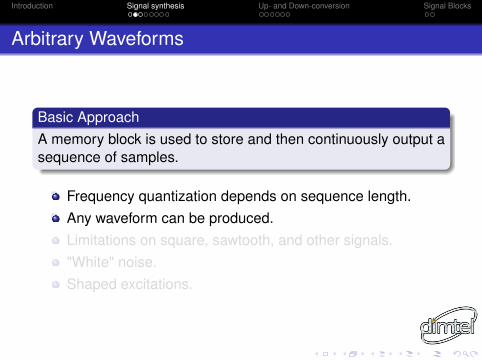
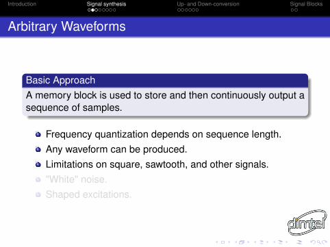
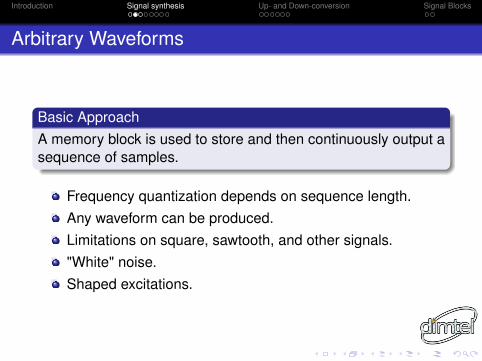
Basic ApproachA memory block is used to store and then continuously output asequence of samples.
Frequency quantization depends on sequence length.Any waveform can be produced.Limitations on square, sawtooth, and other signals."White" noise.Shaped excitations.
Introduction Signal synthesis Up- and Down-conversion Signal Blocks
Arbitrary Waveforms
Basic ApproachA memory block is used to store and then continuously output asequence of samples.
Frequency quantization depends on sequence length.Any waveform can be produced.Limitations on square, sawtooth, and other signals."White" noise.Shaped excitations.
Introduction Signal synthesis Up- and Down-conversion Signal Blocks
LLRF4 Example
Memory block of 2048 samples.Short — causes coarse frequency quantization onsinewaves.Still provides a flexible tool.
Introduction Signal synthesis Up- and Down-conversion Signal Blocks
LLRF4 Example
Memory block of 2048 samples.Short — causes coarse frequency quantization onsinewaves.Still provides a flexible tool.
Introduction Signal synthesis Up- and Down-conversion Signal Blocks
LLRF4 Example
Memory block of 2048 samples.Short — causes coarse frequency quantization onsinewaves.Still provides a flexible tool.
Introduction Signal synthesis Up- and Down-conversion Signal Blocks
Outline
1 Introduction
2 Signal synthesisArbitrary Waveform GenerationCORDICDirect Digital Synthesis
3 Up- and Down-conversionI&Q ProcessingFrequency Conversion
4 Signal BlocksPhase Shifting

Introduction Signal synthesis Up- and Down-conversion Signal Blocks
A Great Tool
COordinate Rotation DIgital Computer — first described byJack E. Volder in 1959.Performs iterative coordinate rotations.Two basic modes:
Rotate an input vector by an arbitrary angle (rotation mode);Rotate an input vector to align with x-axis (vectoring mode).
Applications:Sine and cosine generation;Cartesian to polar transformation;Arctangent computation;Arcsine, arccosine;Extensions to linear and hyperbolic functions.
Introduction Signal synthesis Up- and Down-conversion Signal Blocks
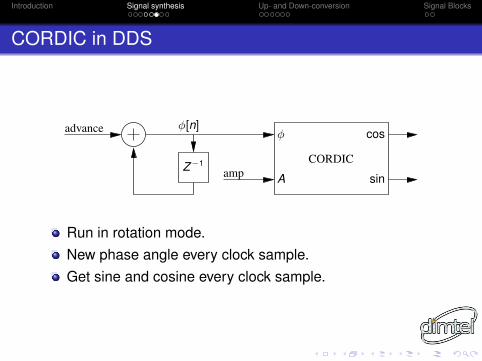
CORDIC in DDS
Z−1 CORDIC
φ[n]advance
amp
φ
A
cos
sin
Run in rotation mode.New phase angle every clock sample.Get sine and cosine every clock sample.
Introduction Signal synthesis Up- and Down-conversion Signal Blocks
Outline
1 Introduction
2 Signal synthesisArbitrary Waveform GenerationCORDICDirect Digital Synthesis
3 Up- and Down-conversionI&Q ProcessingFrequency Conversion
4 Signal BlocksPhase Shifting
Introduction Signal synthesis Up- and Down-conversion Signal Blocks
Topology
A phase accumulator followed by a wave shape generator.Accumulator advance per clock cycle is adjustable:
Changes the frequency;Advance can be modulated as well.
Wave shape generator — memory or CORDIC.With a 30-bit accumulator (MSB=π) frequency quantizationis fs/109.Efficient accumulators (Bresenham).
Introduction Signal synthesis Up- and Down-conversion Signal Blocks
Outline
1 Introduction
2 Signal synthesisArbitrary Waveform GenerationCORDICDirect Digital Synthesis
3 Up- and Down-conversionI&Q ProcessingFrequency Conversion
4 Signal BlocksPhase Shifting
Introduction Signal synthesis Up- and Down-conversion Signal Blocks
I&Q Definition
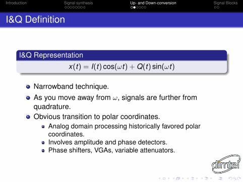
I&Q Representation
x(t) = I(t) cos(ωt) + Q(t) sin(ωt)
Narrowband technique.As you move away from ω, signals are further fromquadrature.Obvious transition to polar coordinates.
Analog domain processing historically favored polarcoordinates.Involves amplitude and phase detectors.Phase shifters, VGAs, variable attenuators.
Introduction Signal synthesis Up- and Down-conversion Signal Blocks
Outline
1 Introduction
2 Signal synthesisArbitrary Waveform GenerationCORDICDirect Digital Synthesis
3 Up- and Down-conversionI&Q ProcessingFrequency Conversion
4 Signal BlocksPhase Shifting
Introduction Signal synthesis Up- and Down-conversion Signal Blocks
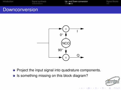
Downconversion
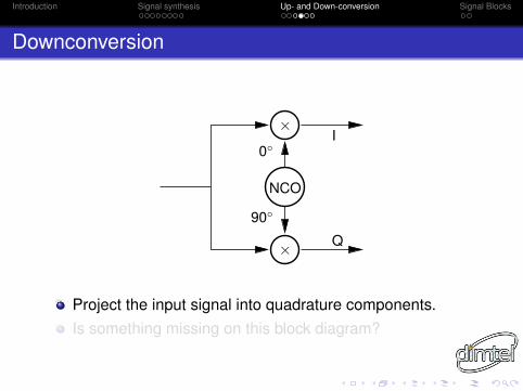
×
×
NCO
Q
0◦
90◦
I
Project the input signal into quadrature components.Is something missing on this block diagram?
Introduction Signal synthesis Up- and Down-conversion Signal Blocks
Downconversion
×
×
NCO
Q
0◦
90◦
I
Project the input signal into quadrature components.Is something missing on this block diagram?
Introduction Signal synthesis Up- and Down-conversion Signal Blocks
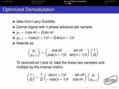
Optimized Demodulation
Idea from Larry Doolittle.Carrier signal with θ phase advance per sample.yn = I cos nθ + Q sin nθ
yn+1 = I cos(n + 1)θ + Q sin(n + 1)θ
Rewrite as(yn
yn+1
)=
(cos nθ sin nθ
cos(n + 1)θ sin(n + 1)θ
) (IQ
)To reconstruct I and Q, take the these two samples andmultiply by the inverse matrix:(
IQ
)=
1D
(sin(n + 1)θ − sin nθ− cos(n + 1)θ cos nθ
) (yn
yn+1
)
Introduction Signal synthesis Up- and Down-conversion Signal Blocks
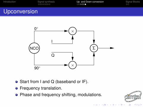
Upconversion
×
×
Σ
0◦
90◦
I
Q
NCO
Start from I and Q (baseband or IF).Frequency translation.Phase and frequency shifting, modulations.
Introduction Signal synthesis Up- and Down-conversion Signal Blocks
Outline
1 Introduction
2 Signal synthesisArbitrary Waveform GenerationCORDICDirect Digital Synthesis
3 Up- and Down-conversionI&Q ProcessingFrequency Conversion
4 Signal BlocksPhase Shifting
Introduction Signal synthesis Up- and Down-conversion Signal Blocks
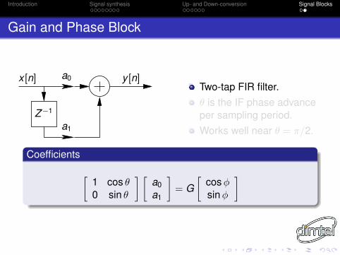
Gain and Phase Block
Z−1
x [n]
a1
a0 y [n]Two-tap FIR filter.θ is the IF phase advanceper sampling period.Works well near θ = π/2.
Coefficients
[1 cos θ0 sin θ
] [a0a1
]= G
[cos φsin φ
]
Introduction Signal synthesis Up- and Down-conversion Signal Blocks
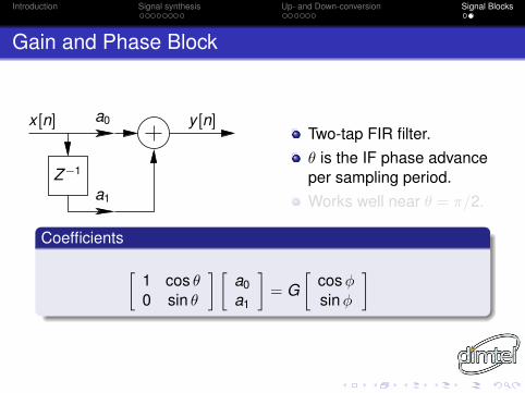
Gain and Phase Block
Z−1
x [n]
a1
a0 y [n]Two-tap FIR filter.θ is the IF phase advanceper sampling period.Works well near θ = π/2.
Coefficients
[1 cos θ0 sin θ
] [a0a1
]= G
[cos φsin φ
]

Introduction Signal synthesis Up- and Down-conversion Signal Blocks
Gain and Phase Block
Z−1
x [n]
a1
a0 y [n]Two-tap FIR filter.θ is the IF phase advanceper sampling period.Works well near θ = π/2.
Coefficients
[1 cos θ0 sin θ
] [a0a1
]= G
[cos φsin φ
]