digital video broadcasting (dvb); upper layer forward error
TRANSCRIPT

!!!!
!!!!!!!!!!!
Digital Video Broadcasting (DVB);
Upper Layer Forward Error Correction in DVB
DVB Document A148 March 2010


3
DVB BlueBook A148
TM4367
Upper Layer F E C in D V B
D V B T M-U L F E C T M Joint Task Force on Upper Layer Forward E r ror Correction
Editor: Laurent Roullet (Alcatel Lucent) Contributors: David Gómez-Barquero (iTEAM-UPVLC)
Cornelius Hellge (Fraunhofer HHI) Luc Ottavj (UDCAST) Thomas Stockhammer (Digital Fountain)
Version: 0.1.00 Date: 25th of January 2010

4
DVB BlueBook A148
Table of Contents
1 Introduction ........................................................................................................................6
1.1 Scope ..........................................................................................................................6 1.2 Definition of Upper Layer FEC..................................................................................8 1.3 Structure of this Document.........................................................................................8 1.4 References ..................................................................................................................9 1.5 Acronyms..................................................................................................................10 1.6 Document History.....................................................................................................11
2 Use Cases Upper Layer FEC............................................................................................13 2.1 Unidirectional File Delivery.....................................................................................13 2.2 Streaming TV Services.............................................................................................14 2.3 Streaming Layered Error Protection.........................................................................16
2.3.1 Application Examples.......................................................................................16 2.3.2 Layered Error Protection ..................................................................................17
2.4 Mobile Data Services over Satellite .........................................................................18 3 DVB specifications including Upper Layer FEC.............................................................20
3.1 Introduction ..............................................................................................................20 3.2 MPE-FEC .................................................................................................................20 3.3 MPE-IFEC................................................................................................................21 3.4 Link Layer FEC in DVB RCS+M ............................................................................21 3.5 AL-FEC in IPDC for File Delivery ..........................................................................22 3.6 AL-FEC in DVB-IPTV for Streaming .....................................................................23 3.7 AL-FEC in DVB-IPTV for Content Download Services.........................................24
4 FEC codes for Upper Layer FEC .....................................................................................25 4.1 Metrics for UL-FEC codes .......................................................................................25 4.2 Performance Ideal Code ...........................................................................................25 4.3 Reed-Solomon Codes ...............................................................................................26
4.3.1 Overview ..........................................................................................................26 4.3.2 Specification .....................................................................................................26 4.3.3 Memory Requirements .....................................................................................27 4.3.4 Additional Information .....................................................................................27
4.4 Raptor Codes ............................................................................................................28 4.4.1 Overview ..........................................................................................................28 4.4.2 Specification .....................................................................................................29 4.4.3 Memory Requirements .....................................................................................29 4.4.4 Additional Information .....................................................................................29
4.5 Comparison of Codes ...............................................................................................30 5 Basic Design Considerations ............................................................................................31
5.1 UL-FEC Database.....................................................................................................31 5.1.1 Exogenous Aspects...........................................................................................31 5.1.2 Internal Aspects ................................................................................................33
5.2 UL-FEC Cookbook...................................................................................................40 6 Summary...........................................................................................................................44
6.1 Main outcomes .........................................................................................................44 6.2 Known limitations ....................................................................................................46 6.3 Potential future work for DVB on Upper Layer FEC ..............................................46
6.3.1 Software-based FEC using Reed-Solomon codes ............................................46 6.3.2 Layer-Aware FEC for SVC ..............................................................................47

5
DVB BlueBook A148
6.3.3 MPE-IFEC for other Systems (DVB-H, DVB-T2, DVB-NGH)......................48 7 Annex A – Details on Reed-Solomon and Raptor Codes.................................................50
7.1 Reed-Solomon Codes ...............................................................................................50 7.1.1 Code Performance ............................................................................................50 7.1.2 Complexity .......................................................................................................51 7.1.3 Decoding Algorithms .......................................................................................52
7.2 Raptor Codes ............................................................................................................54 7.2.1 Code Performance ............................................................................................54 7.2.2 Complexity .......................................................................................................54 7.2.3 Decoding Algorithms .......................................................................................54
8 Annex B – Detailed Examples of Upper Layer FEC........................................................58 8.1 MPE-FEC for DVB-H Streaming Services ..............................................................58
8.1.1 Concept.............................................................................................................58 8.1.2 Implementation.................................................................................................59
8.2 AL-FEC for DVB-H File Delivery Services ............................................................60 8.2.1 Concept.............................................................................................................60 8.2.2 FLUTE..............................................................................................................62
8.3 MPE-IFEC for DVB-SH Streaming Services ..........................................................63 8.3.1 Concept.............................................................................................................63 8.3.2 MPE-IFEC Reed-Solomon Approach ..............................................................65 8.3.3 MPE-IFEC Raptor Coding Approach...............................................................66 8.3.4 Fast Zapping Techniques..................................................................................67
8.4 Multi-Burst FEC Protection for DVB-H Streaming Services ..................................69 8.5 MPE-FEC/MPE-IFEC in DVB-H/SH for Layered Streaming Transmission ..........69
8.5.1 Overview ..........................................................................................................69 8.5.2 MPE-FEC for Layered Transmission in DVB-H/SH.......................................70 8.5.3 MPE-IFEC for Layered Transmission in DVB-H/SH......................................70
8.6 DVB-RCS+M for Mobile Satellite Data Services....................................................72 8.6.1 Overview ..........................................................................................................72 8.6.2 FEC Architectures ............................................................................................72
9 Annex C – Illustrative Performance Evaluation Examples for Upper Layer FEC...........74 9.1 Synthesis...................................................................................................................74 9.2 SVC Layered Transmission in Terrestrial Context (DVB-H) ..................................75
9.2.1 SVC Layered Transmission in Terrestrial Context (DVB-H) using Intra-Burst FEC (MPE-FEC) ..............................................................................................................77 9.2.2 SVC Layered Transmission in Terrestrial Context (DVB-H) using Intra-Burst FEC and Layer-Aware FEC (LA-FEC)............................................................................79 9.2.3 SVC Layered Transmission in Terrestrial Context (DVB-H) using Inter-Burst FEC (MPE-iFEC) .............................................................................................................81 9.2.4 Layered Transmission in Terrestrial Context (DVB-H) using Inter-Burst FEC (MPE-iFEC) and Layer-Aware FEC ................................................................................84
9.3 SVC Layered Transmission in Satellite Context (DVB-SH) ...................................88 10 Annex D - Possible Integration of the Layer-Aware Approach in the DVB toolbox ..92
10.1 Integration in the CDP toolbox.................................................................................92 10.2 Integration in the MPE-IFEC toolbox ......................................................................95
11 Bibliography .................................................................................................................96

6
DVB BlueBook A148
1 Introduction
1.1 Scope Virtually any communication system employs some kind of Forward Error Correction (FEC) coding. FEC mechanisms rely on the transmission of repair information to protect loss events on underlying levels without a need for feedback (return channel), such that the receiver can detect and possibly correct errors occurred during the transmission.
The error correction capability of a FEC code depends on the distribution of the errors over time. Ideally, if the channel is memory less and the errors are uniformly distributed it is possible to cope with error rates equal to the rate of parity data transmitted. However, in practice long error bursts are common meaning that the channel cannot be considered memory less. This is particularly evident for wireless communication systems, where the transmission errors due to the impairments of the radio channel are heavily correlated due to signal fading as the result of multipath propagation and shadowing that mobile users experience in the field when moving across the service area. In addition, channel noise and impulse interferences also produce bursty error patterns.
During such bursts of error, the error rate can be very high, requiring a very robust FEC. However, in the interim between consecutive bursts of errors the error rate may be significantly lower. Therefore, if the FEC code is statically confierror rate in mind it may be ineffective or insufficient, especially if the coded data is sequentially transmitted. Finally, it should be pointed out that in some cases the transmission can even be temporarily completely interrupted, being simply not possible to correct any error.
This performance degradation caused by the memory of the channel can be mitigated by using an interleaver to distribute the coded data over time so that bursty errors in the interleaved data are more uniformly distributed temporally after de-interleaving, and therefore easier to correct with FEC codes. This comes at the expense of increased latency and more memory requirements at the receivers. Note also that the channel noise is less variable when averaged over longer time intervals, and thus the relative amount of protection needed to achieve a given residual error rate is reduced for larger interleaving. How effective an interleaver is depends mainly on the statistical correlation between the reception conditions of the interleaved data. The larger the interleaving depth, the better the interleaver can be expected to work. Indeed if a sufficiently large time interleaving is employed, it is possible to cope with as many errors as in the best case (i.e., for an infinite interleaving the performance would be the same as for a memory less channel).
Figure 1 shows a simplified illustration of the time-averaging effect on the received Signal-to-Noise Ratio (SNR) as the result of interleaving.
< SNR threshold Decoding not successfull
Decoding successfull
Effective SNR after de-interleaving
Interleaver duration T ime
Rec
eive
d SN
R
F igure 1: T ime interleaving as time-averaging effect of the received SNR within the interleaving length.

7
DVB BlueBook A148
Averaging out good and bad reception conditions it is possible to recover from reception instants with bad signal quality as soon as the mean SNR exceeds the required threshold. On the other hand, if the mean SNR is below the reception threshold, the reception can actually even worsen as errors are spread over a longer time span.
We can categorize FEC mechanisms into those working at the physical layer and FEC mechanisms working at any upper layer above it, such as the link or application layers.
Physical layer FEC codes work at the bit level and are traditionally implemented as part of the radio interface for wireless communication systems. They theoretically provide the most effective protection against channel noise, as they can exploit channel state information using soft decision decoding. In soft decision decoding, each bit is assigned a confidence value ranging from a maximum confidence zero to a maximum confidence one, which can be utilized by the decoder for more reliable probabilistic decoding. However, in practice, due to on-chip memory and decoding complexity constraints (especially for handheld devices), the maximum time interleaving depth is rather small. The memory requirement for FEC decoding is directly proportional to the service data rate, interleaving duration and the rate of parity data transmitted, which is usually large at the physical layer. For first generation DVB systems, the time interleaving at the physical layer it is usually in the order of few milliseconds or less, whereas for the some second generation DVB systems it can take value of several seconds.
As a consequence, physical layer FEC is often combined with an upper layer FEC code, accepting a weaker performance in terms of level of protection, but achieving a better trade-off between overall system error protection and system implementation. In addition, in many applications there is a desire to extend a legacy bearer for other purposes, such as in the case with DVB-H and the DVB-T physical layer, or the use of DSL connections for IPTV distributions. In these cases, the extension of the physical layer FEC may simply be impossible, and additional FEC protection can be only provided in upper layers.
Upper layer FEC works in conjunction with physical layer FEC to produce a more efficient overall configuration. By operating above the physical layer, it is possible to provide protection against longer losses with larger interleaving depths that physical layer cannot support. However, the optimization of the overall system FEC configuration becomes a cross-layer FEC configuration problem which is more difficult to solve. In contrast to physical layer FEC that corrects bit errors, upper layer FEC recovers from packet losses and are block codes that work with fixed-size blocks (packets) of bits or symbols of a predetermined size using erasure decoding. In upper layer FEC, packets are considered either correct or lost (Packet Erasure Channels or PEC, by opposition to Bit Erasure Channels or BEC). Therefore, it is necessary to indicate whether each packet is correctly received or not (e.g., with checksums as Cyclic Redundancy Check, CRC), such that the upper layer FEC decoder sees a virtual erasure channel.
Examples of physical layer FEC codes that are adopted in DVB standards are:
Convolutional codes in DVB-T/H.
Turbo-codes in DVB-SH.
Low-Density-Parity-Check (LDPC) codes in DVB-S2 and DVB-T2.
It should be pointed out that convolutional and LPDC codes are concatenated in the physical layer with an additional (outer) FEC block code with an interleaver in-between. In particular, the convolutional code adopted in DVB-T/H is concatenated with a Reed-Solomon (RS) code to correct physical layer MPEG-2 Transport Stream (TS) packets with only few erroneous bytes, and the LDPC code adopted in DVB-S2/T2 is concatenated with a BCH (Bose-

8
DVB BlueBook A148
Chaudhuri-Hochquenghem) code to remove the error floor produced by the LDPC at low bit error rates. These codes are not considered as upper layer FEC as they are an integral part of the physical layer FEC.
Examples of upper layer FEC codes in DVB are Reed-Solomon and Raptor codes.
1.2 Definition of Upper Layer FEC In general, an upper layer F EC code is any FEC code operating above the physical layer at the link or application layer using erasure decoding.
An upper layer FEC encoder generates encoding symbols from a sequence of source packets that are combined in a source data block. Let k denote the number of source symbols us assume the source block consists. An upper layer FEC encoder generates encoding symbols out of the k source symbols, k/n being the code rate. The ratio of the number of additional symbols (n-k) to the number k of original symbols is generally referred to as the F EC overhead. If a so-called systematic code is applied, the first k symbols produced by the encoder are simply the k source symbols, and the remaining n-k symbols represent additional repair (parity) symbols. In contrast, non-systematic codes produce a set of encoding symbols that do not contain the original source symbols.
For a systematic code, obviously, if all source symbols are correctly received, no parity data is needed at all. Otherwise, with a suitable subset of r encoding symbols, such that , the decoder can reconstruct the source data file. Perfect codes are those where any parity symbol can correct any lost systematic symbol. In such case, it does not matter which symbols are received but that a sufficient amount of symbols are received correctly. The exact value of r depends on the coding scheme used. The average amount of symbols E{r} necessary is a good indication of the quality of the code. Based on the average amount of necessary symbols the reception overhead, , can be defined as = (E{r}-k)/k.
Note that the mapping of packets to symbols and vice versa may be a one-to-one mapping, or it may be based on some specific mapping algorithms. If symbols and packets are not aligned, then packet losses at the physical layer typically result in higher symbol loss rates on the link and application layers, as one single erroneous physical layer packet can cause the loss of several symbols of the upper layer FEC. However, in practice as errors at the physical layer are usually correlated and several consecutive packets are lost, the symbol loss rate is only marginally higher than the packet loss rate.
1.3 Structure of this Document This document is structure as follows:
1) Chapter 2 describes the reference uses cases of upper layer FEC.
2) Chapter 3 lists all existing DVB upper layer FEC specifications.
3) Chapter 4 highlights the performance measures for upper layer FEC codes and provides an overview of the Reed-Solomon and Raptor codes in use within DVB.
4) Chapter 5 schemes.
5) Chapter 6 summarizes the document, and provides insights into possible future work on UL-FEC.
6) Annex A (chapter 7) provides detailed information on Reed-Solomon and Raptor performance and decoding algorithms.

9
DVB BlueBook A148
7) Annex B (chapter 8) provides detailed examples of usage of UL-FEC codes within DVB.
8) Annex C (chapter 9) provides illustrative performance evaluation results for some UL-FEC codes.
9) Annex D (chapter 10) shows how the Layer-Aware FEC approach could be integrated into the DVB toolbox.
1.4 References
[1]
[2] ITU-T Recommendation H.264 / ISO/IEC 14496 10:2008: Information technology Coding of audio visual objects - Part 10: Advanced Video Coding
[3] ETSI Video and Audio Coding in Broadcasting Applications based on the MPEG-2
[4] ETSI TS 102 005, Digital Video Broadcasting (DVB); Specification for the use of Video and Audio Coding in DVB services Delivered Directly over IP Protocols,
[5] Digital Video Broadcasting (DVB); Framing Structure, Channel Coding and Modulation for 11/12 GHz Satellite Services
[6] Interaction Channel for
[7] ETSI EN 302 307, Digital Video Broadcasting (DVB); Second Generation Framing Structure, Channel Coding and Modulation Systems for Broadcasting, Interactive Services, News Gathering and other Broadband Satellite
[8]
[9] ansmission System for Handheld Terminals (DVB-
[10] Satellite Services to Handheld D
[11] -SH implementation
[12] DVB Bluebook Digital Video Broadcasting (DVB); MPE IFEC,
[13] ETSI TS 102 472 v1.3.1, IP Datacast over DVB-H: Content Deli
[14] teraction channel for Satellite Distribution Systems; Guidelines for the use of EN 301 790 in Mobile
[15] ETSI TS 126 346 (3GPP TS 26.346 Release 6 Universal Mobile Telecommunications System (UMTS); Multimedia Broadcast/Multicast Service (MBMS); Protocols and
[16] IETF RFC 3695 Compact Forward Error Correction (FEC) Schemes
[17] TS 102 584, Digital Video Broadcasting (DVB); DVB-SH Implementation Guidelines

10
DVB BlueBook A148
[18] IETF RFC 3926, -
[19] ETSI TR 102 591, gital Video Broadcast (DVB); IP Datacast: Content Delivery Protocols (CDP) Implementation Guidelines Part 1: IP Datacast over DVB-
[20] ETSI TS 102 034 Digital Video Broadcasting (DVB); Transport of MPEG-2 TS based DVB Services over IP based Networks
[21] SMPTE Specification 2022-1 orward Error Correction for Real-time Video/Audio Transport over IP Networks,
[22] ATIS/IIF: http://www.atis.org/IIF/index.asp
[23] ETSI TISPAN http://www.etsi.org/tispan/
[24] ITU-T IPTV Focus group proceedings (http://www.itu.int/dms_pub/itu-t/opb/proc/T-PROC-IPTVFG-2008-PDF-E.pdf)
[25] Open IPTV Forum Technology Choices (http://www.openiptvforum.org/docs/Release1/Release1_1/OIPF-T1-R1-Specification-Volume-4-Protocols-V1_1-2009-10-08.pdf)
[26] DVB Bluebook ,
[27] -
[28]
[29]
[30] ,
[31] ,
[32]
[33] ETSI TR 102 591, : Content Delivery Protocols (CDP) Implementation Guidelines Part 2: IP Datacast over DVB-S
[34] ETSI TS 102 772 -Protocol Encapsulation - inter-burst Forward Error Correction MPE-
1.5 Acronyms
A L C Asynchronous Layered Coding
A L-F E C Application Layer FEC
A V C Advanced Video Coding
B C H Bose-Chaudhuri-Hochquenghem
C DP Content Delivery Protocols
C R C Cyclic Redundancy Check
DSL Digital Subscriber Line
D V B-H Digital Video Broadcast Handhelds
D V B-N G H Digital Video Broadcast Next Generation Handhelds

11
DVB BlueBook A148
D V B-R CS Digital Video Broadcast Return Channel Satellite
D V B-S Digital Video Broadcast Satellite
D V B-S2 Digital Video Broadcast Second Generation Satellite
D V B-SH Digital Video Broadcast Satellite Services to Handhelds
D V B-T Digital Video Broadcast Terrestrial
D V B-T2 Digital Video Broadcast Second Generation Terrestrial
ESI Encoded Symbol ID
F E C Forward Error Correction
F L U T E File Delivery over Unidirectional Transport
GSE Generic Stream Encapsulation
IP Internet Protocol
IPD C IP Datacast
IPT V Internet Protocol Television
L C T Layered Coding Transport
L DPC Low-Density Parity Check
L A-F E C Layer Aware FEC
L L-F E C Link Layer FEC
U L-F E C Upper Layer FEC
UPD User Datagram Protocol
MPE Multi Protocol Encapsulation
MPE-F E C Multi Protocol Encapsulation FEC
MPE-I F E C Multi Protocol Encapsulation Inter-burst FEC
MPE G Moving Picture Experts Group
RS Reed-Solomon
R TP Real-time Transport Protocol
SV C Scalable Video Coding
T CP Transmission Control Protocol
TS Transport Stream
1.6 Document History Date Version Remarks November 11th 2008 V0.0.1 First draft collection of different contributions. November 14th, 2008 V0.0.2 Agreed draft version after Online Meeting #4
taking into account comments from iTEAM-UPVLC.
November 18th, 2008 V0.0.3 Agreed version before TM#78.

12
DVB BlueBook A148
June 1st, 2009 v0.0.6 Release 6. November 16th, 2009 v.0.0.7 Agreed version before TM#82. Re-structure of
the document, moving details into annexes. January 25th, 2010 v.1.0.0 Submission to TM#83 for approval.

13
DVB BlueBook A148
2 Use Cases Upper Layer FEC This chapter describes the four main categories of usage today considered in DVB:
File delivery. Streaming TV services. Layered error protection Satellite data services.
2.1 Unidirectional File Delivery It can be used
for most content types including multimedia clips, high quality music files, digital newspapers, software download, etc. File delivery poses significant challenges in terms of reliability and integrity of the data, as even a single bit error can corrupt the entire file and make it useless to the receiver. Hence, error-free reception is typically required. On the other hand, latency and delay constraints are usually relaxed in file delivery applications, as the receiver will start processing the information only after the entire file has been received.
In bidirectional applications, TCP (Transmission Control Protocol) has been established to provide a reliable data transmission, even for very large files [1]. However, the delivery of files over unidirectional links with no backward channel poses significant challenges, in particular if the packet data losses are common. Filecasting applications over mobile and satellite networks generally fall into this category. File delivery over wired IP multicast networks, for example in IPTV environments, poses similar challenges.
Filecasting applications may be setup in different ways:
In scheduled distribution, the start of the delivery of the files is announced to the receiver population beforehand such that all interested receivers can join the download session at the appointed time. The session is generally terminated when the transmitter anticipates that a sufficient amount of receivers have successfully received the file. Scheduled distribution itself may be differentiated in applications with and without timing constraints. Time constraints require that the file is acquired by a sufficient amount of receivers within a certain amount of time. This type of distribution may for example be used for on-demand applications or pseudo-streaming over unreliable networks (for which the content stream is split in files that are delivered independently, see Section 2.2). In contrast, applications without time constraints support background transfer in which users are not aware of the transmission.
In carousel distribution, receivers can join the download session at any point of time independent of other receivers in an asynchronous fashion. The transmission of the files is virtually unbounded and the receivers only leave the carousel when they have received the file. In static carousel distribution, a file with the same content is distributed, whereas in dynamic carousels the files may change over time.
Upper layer FEC can be very beneficial for file download services in unidirectional multicast/broadcast environments when a return channel is either not available or when the use of return channels is impractical because of the large number of receivers. Upper layer FEC shortens the transmission duration and reduces bandwidth requirements while ensuring that the receivers reliably obtain the file.
14
DVB BlueBook A148
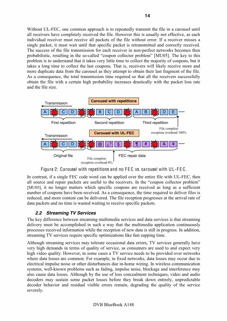
Without UL-FEC, one common approach is to repeatedly transmit the file in a carousel until all receivers have completely received the file. However this is usually not effective, as each individual receiver must receive all packets of the file without error. If a receiver misses a single packet, it must wait until that specific packet is retransmitted and correctly received. The success of the file transmission for each receiver in non-perfect networks becomes then probabilistic, resulting in the so- coupon collector p [MU05]. The key to this problem is to understand that it takes very little time to collect the majority of coupons, but it takes a long time to collect the last coupons. That is, receivers will likely receive more and more duplicate data from the carousel as they attempt to obtain their last fragment of the file. As a consequence, the total transmission time required so that all the receivers successfully obtain the file with a certain high probability increases drastically with the packet loss rate and the file size.
Transmission
C B C D E
A
B D E
First repetition
A A B C D E
Carousel with repetitions
Transmission
¿? B C D E
ä
@ §
ç
Original file
A ¶ # & ¥
Second repetition Third repetition
FEC repair data
Carousel with UL-FEC
File complete reception overhead 0%
File complete reception overhead 100%
F igure 2: Carousel with repetitions and no F E C vs. carousel with U L-F E C .
In contrast, if a single FEC code word can be applied over the entire file with UL-FEC, then all source and repair packets are useful to the receivers. In t coupon collector p [MU05], it no longer matters which specific coupons are received as long as a sufficient number of coupons have been received. As a consequence, the time required to deliver files is reduced, and more content can be delivered. The file reception progresses at the arrival rate of data packets and no time is wasted waiting to receive specific packets.
2.2 Streaming TV Services The key difference between streaming multimedia services and data services is that streaming delivery must be accomplished in such a way that the multimedia application continuously processes received information while the reception of new data is still in progress. In addition, streaming TV services require specific optimizations like fast zapping time.
Although streaming services may tolerate occasional data errors, TV services generally have very high demands in terms of quality of service, as consumers are used to and expect very high video quality. However, in some cases a TV service needs to be provided over networks where data losses are common. For example, in fixed networks, data losses may occur due to electrical impulse noise or other disturbances due in-home wiring. In wireless communication systems, well-known problems such as fading, impulse noise, blockage and interference may also cause data losses. Although by the use of loss concealment techniques, video and audio decoders may sustain some packet losses before they break down entirely, unpredictable decoder behavior and residual visible errors remain, degrading the quality of the service severely.
15
DVB BlueBook A148
Various solutions are available and implemented in various degrees to reduce and/or eliminate packet loss. Some of the solutions are not mutually exclusive, but may very well complement each other: to avoid loss problems on access and distribution networks below the transport layer, powerful physical layer FEC mechanisms and link layer retransmission schemes may be implemented. Physical layer FEC theoretically provides the most effective protection against channel noise, however it generally has limitations in terms of complexity and terminal memory to overcome impulse noise and burst losses. Another solution to the packet loss problem is the use of retransmission protocols. Retransmissions resolve packet loss by requesting lost packets from the network or the server. While this is a potentially viable solution to resolve packet loss, retransmission generally requires a back channel and does not scale well in multicast and broadcast environments.
Solutions on the physical layer usually can only overcome the problems occurring at a single hop, but do not provide end-to-end QoS. If QoS is to be provided over several links at once, it is desirable that a QoS solution is implemented on the respective layer. This approach may also minimize the end-to-end delay. The use of service specific QoS tools is desirable, particularly if different services may require different QoS levels. But also within one service there may be the desire to provide better QoS to certain streams. Such service specific QoS is usually easier to implement on higher layers. Finally, in many cases there is a desire to extend a generic access system or legacy bearer for other purposes. Examples are the use of the DVB-T physical layer for DVB-H, or the use of DSL connections for IPTV distributions. In such cases it is desired to reuse legacy equipment in networks and end user devices, such that the extension of the physical layer FEC may be economically not viable.
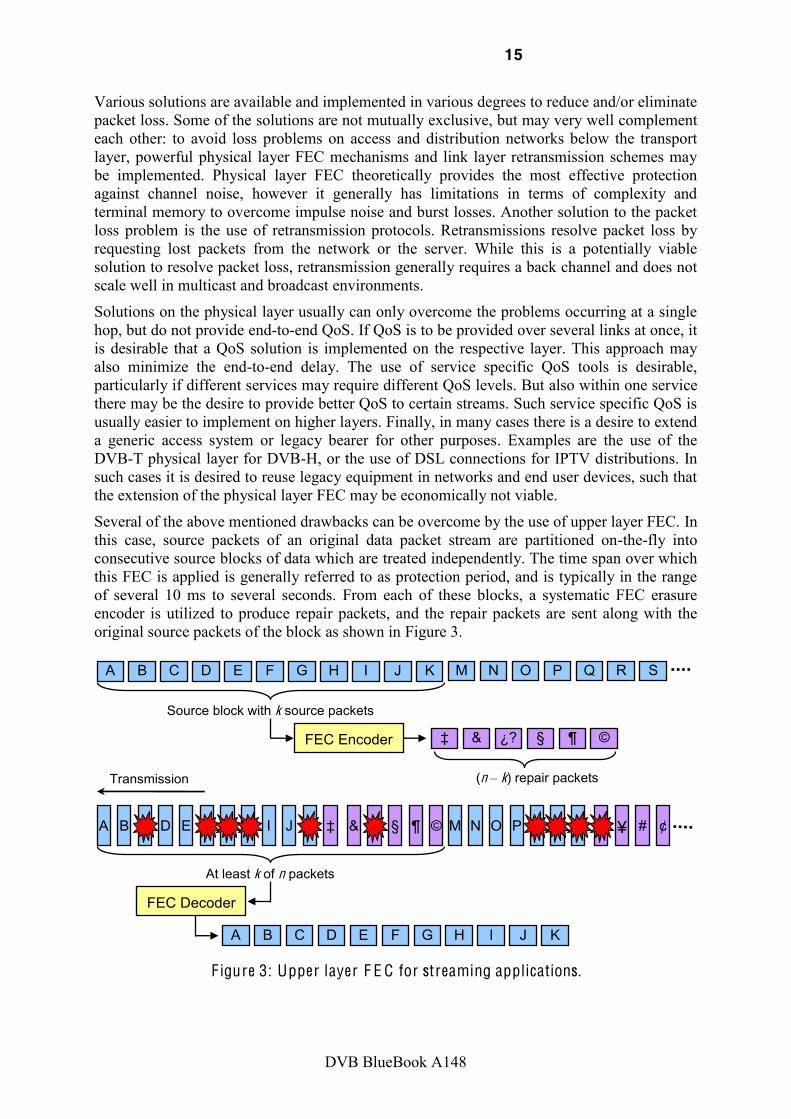
Several of the above mentioned drawbacks can be overcome by the use of upper layer FEC. In this case, source packets of an original data packet stream are partitioned on-the-fly into consecutive source blocks of data which are treated independently. The time span over which this FEC is applied is generally referred to as protection period, and is typically in the range of several 10 ms to several seconds. From each of these blocks, a systematic FEC erasure encoder is utilized to produce repair packets, and the repair packets are sent along with the original source packets of the block as shown in Figure 3.
Transmission
H B C D E
F
G I J
Source block with k source packets
A K S M N O P
Q
R
FEC Encoder §
&
¿?
¶ ©
(n k) repair packets
H B C D E
F
G I J
A K S M N O P
Q
R
At least k of n packets
FEC Decoder
H B C D E
F
G I J
A K
? & § ¶ © ¥ # ¢
F igure 3: Upper layer F E C for streaming applications.

16
DVB BlueBook A148
At the receiver, the received stream is also processed as blocks. The upper layer FEC decoder uses all the source and repair packets that are received from a particular source block to recover it. Ideally, the k source packets of a source block can be reconstructed from any k of the source and repair packets for that source block. In this case the transmitted stream is resilient to the loss of up to n-k lost packets out of n transmitted packets per source block.
The major design parameters of the upper layer FEC code are the FEC overhead and the protection period. They determine the trade-off between protection level against packet loss and the capacity reduction and the latency introduced. Therefore, a careful selection of such parameters depending on the service requirements is essential.
2.3 Streaming Layered Error Protection The Scalable Video Coding (SVC) [2] design is an extension of the H.264/AVC video coding standard, which has been recently adopted within the DVB video coding portfolio, [3] and [4]. An SVC bitstream can be structured so that devices with different capabilities can decode different parts of the bitstream and achieve visual qualities as if they had been delivered by single layer bitstreams of the same rate that had been encoded targeting their specific requirements. In SVC, the so-called base layer provides the lowest quality level and is an H.264/AVC compliant bitstream, which ensures backward-compatibility with existing receivers. Each additional decoded enhancement layer increases the video quality in a certain dimension. SVC allows up to three different scalability dimensions (temporal, spatial, fidelity) within one bit-stream. Some exemplary applications using a combination of SVC and upper layer FEC are described next.
2.3.1 Application Examples
2.3.1.1 Support of heterogeneous devices and conditional access Due to the increasing heterogeneity of devices in the market (e.g. cellphones, smartphones, netbooks, laptops), broadcast systems must be able to offer services for different device types with different capabilities to increase the accessibility of services by providing a minimum quality level for basic advanced terminals. SVC allows providing such services in a bandwidth efficient way as exemplary shown in [SW07] where SVC saves up to 20% in average compared to a simulcast transmission.
Using SVC, selective encryption of particular operation points of the scalable bitstream can be used in order to allow applications like free preview at reduced quality (e.g. picture resolution) and an encrypted enhancement layer with billing [SHM+07]. The combination of SVC and upper layer FEC allows for an optimized protection for both layers and introducing service oriented protection, e.g. the free service has a lower reliability compared to the premium service. In the scenario depicted in Figure 4, the free available base layer (layer 0) has a lower resolution (QVGA) and a lower protection, in such a way that the service can only be received under good reception conditions. If a client has access to the VGA layer (layer 1) it does not only receive a higher resolution, but it also experiences a more stable service due to the additional protection for layer 0 in layer 1. Such a system also allows for supporting heterogeneous devices as in this example for QVGA and VGA devices.

17
DVB BlueBook A148
!
QVGA layer 0
VGA layer 1 FEC 1
FEC 0
SVC Server
"#$$!%$#&'($
)#$*'+*!%$#&'($
FEC 0
F igure 4: Use case with free access to the base layer (layer 0) and conditional access to the enhancement layer (layer 1). The decoding of both layers provides higher quality
and reliability due to the additional protection for the base layer .
2.3.1.2 Extended service coverage and graceful degradation behavior In this use case the combination of SVC and upper layer FEC increases the coverage of a service and introduces a graceful degradation behavior when entering bad reception conditions. In the scenario shown in Figure 5 the SVC stream consists of two quality layers. The base layer has a higher protection than the enhancement layer. Such a service would provide a high quality service in a densely populated areas and a lower quality service in a rural area. When entering the rural area the receiver would experience only a drop in quality but no video outage (graceful degradation). Such a protection scheme can be applied to services for heterogeneous devices. Due to the existing quality layers in such services, such a graceful degradation behavior would come without any additional costs in terms of bit rate.
High quality
Low quality (base layer)
High quality (base layer + enh. layer)
F igure 5: One service providing high quality for reception in urban area and low quality in rural areas. Mobile users experience a graceful degradation behavior when entering
rural areas.
2.3.2 Layered Error Protection Due to inter-layer prediction an SVC stream has various inter-layer dependencies. Figure 6 depicts a simplified dependency structure using spatial scalability as an example. The VGA enhancement layer depends on the QVGA base layer and cannot be decoded in an error free manner without the QVGA layer.

18
DVB BlueBook A148
!!
QVGA
VGA
e.g.
spa
tial s
cala
bilit
y
time
QVGA
VGA
QVGA
VGA
Dep
ende
ncie
s
Dep
ende
ncie
s
Dep
ende
ncie
s
F igure 6: Simplified inter layer dependencies using spatial scalability.
As a result of such inter-layer dependencies, different layers of the SVC bit streams are of different importance, and therefore SVC requires more flexibility when assigning protection so that more important layers require more protection than less important layers. Such an unequal error protection (UEP) scheme is illustrated in Figure 7, where two layers are transmitted over different time-slices (one after the other to save power consumption). In the figure, the more important base layer has a lower code rate and therefore a higher protection than the enhancement layer.
F igure 7: Protection of layered media st ream with two layers in different time slices.
Unequal er ror protection due to different importance of layers. The optimized protection of a layered media stream such as SVC requires the knowledge of the stream structure and the service application. To provide such service- and stream-specific information to a physical layer FEC would require heavy cross-layer communication which may be theoretically possible but it is very complex to achieve in practice. The use of an upper layer FEC is, naturally, a more application-aware solution, and it can provide an optimized protection for the layered m. Moreover, it avoids (AL-FEC) or reduces (LL-FEC) cross-layer communication compared to physical layer FEC.
2.4 Mobile Data Services over Satellite Satellite communications are a natural solution to efficiently distributing information over very large geographical areas. As mobile multimedia wireless communications continue to grow, satellite systems are being considered for mobile usage to provide global connectivity for IP-based broadband multimedia services. Particularly in Europe, due to the success of digital video broadcasting via satellite using DVB-S [5], DVB-RCS [6], and DVB-S2 [7]; and given the large available bandwidth in the Ku/Ka band.
However, generally these standards and systems have not been designed for mobile use. Terminals installed in a mobile platform, such as train, ship, or aircraft, are exposed to challenging environments that will impact system performance.
In general, mobile terminals will have to cope with from the following Land Mobile Satellite (LMS) channel features:
Enhancement Layer
Base Layer
Source Data
Enhancement Layer
Base Layer
Parity Data SVC
Predictions

19
DVB BlueBook A148
Short-term fading due to multipath coming from nearby environment.
Medium-long term fading due to shadowing.
Rain attenuation.
Doppler frequency shifts.
Satellite obstruction due to cables, power arches, tunnels, bridges, etc.
Frequent handovers.
Impairments in the synchronization acquisition and maintenance.
Additionally, each particular application scenario may have specific impairments. For example, the railway scenario is further impeded by the presence of metallic obstacles along electrified lines and long blockages due to the presence of tunnels and large train stations.
Countermeasures are required to compensate for such disturbances, which if left unaccounted for, may result in often and long outages and packet loss periods. A typical approach to compensate for packet loss in unicast data delivery is the application of automatic repeat request (ARQ) schemes. However, the round-trip times on satellite networks makes such schemes impracticable, in particular if certain delay requirements are to be fulfilled. In addition, most satellite applications imply multicasting/broadcasting that prevents the use of retransmissions due to scalability reasons. Therefore, the use of upper layer FEC may be an extremely interesting approach.

20
DVB BlueBook A148
3 DVB specifications including Upper Layer FEC
3.1 Introduction Different upper layer FEC solutions are available in DVB in several specifications for different applications. The solutions are partially integrated in the application layer above the IP level, referred to as Application Layer FEC (AL-FEC), or in the link layer below the IP level, referred to as Link Layer FEC (LL-FEC). Figure 8 provides a simplified protocol stack of different DVB systems and highlights where upper layer FEC is integrated in DVB. DVB includes upper layer FEC in streaming and file delivery solutions on the application layer, as well as in multicast and unicast link layer protocols MPE (Multi Protocol Encapsulation) and GSE (Generic Stream Encapsulation). This section provides an overview, a brief introduction and references to existing upper layer FEC specifications in DVB.
!"#$%&'( )*'+$,-*).('#/*.012.132.42.432.452./)& 6 !57.89:
;!9<3.14
<49
;!9<3.14
;!9 ;!9=89: ;!9=>89:
>!.?@()%&'$).A.@+%&'$)
B)"/* C/(%D/*#/EFE.1:!
GH!
4)*/'?%+F.C/(%D/*#I*'?/J-*K
8%(/.C/(%D/*# I*'?/J-*K08LG196
MAN.'+C.HM1M.$/*D%&/$
89: 89:
G,,/*('#/*
L-J/*('#/*
L%+K('#/*
M,,(%&')%-+('#/*
F igure 8: Simplified D V B Protocol Stack including F E C technology .
3.2 MPE-FEC The Multiprotocol Encapsulation FEC is specified in ETSI EN 301 192 [8] DVB Specification for Data Broadcastingprocess of the DVB-H standard in order to compensate for the performance degradations of DVB-T under mobility conditions. The degradation is due to lack of a physical layer time interleaver long enough to cope with fast fading and to improve the tolerance to impulse interference. The MPE-FEC uses a Reed-Solomon code that is defined in Section 9.5 of [8].
The MPE-FEC was introduced in such a way that MPE-FEC ignorant (but MPE capable) DVB receivers are still able to receive the MPE stream in a fully backwards-compatible way. This backwards compatibility holds regardless of whether MPE-FEC is used with or without time slicing. The use of MPE-FEC is not mandatory and is defined separately for each elementary stream in the transport stream. For each elementary stream it is possible to choose whether or not MPE-FEC is used, and if it is used, to choose the trade-off between FEC overhead and transmission robustness.
21
DVB BlueBook A148
In DVB-H [9], MPE-FEC is optional for the receiver, but recommended to be used on elementary streams using time slicing.
In DVB-SH [10], MPE-FEC may be used in the same way as in DVB-H but not at the same time as MPE-IFEC.
The implementation, usage and configuration of MPE-FEC are described in Annex 8.
3.3 MPE-IFEC Multiprotocol Encapsulation Inter-burst FEC was initially published as part of the DVB Bluebook on DVB-SH implementation guidelines [11]. It is now a separate blue book [12] and an ETSI specification [34]. The specification may also DVB Specification for Data Broadcasting [8].
MPE-IFEC was developed during the standardization process of the DVB-SH standard in order to support reception in situations of long signal outages spanning several consecutive time slice bursts. Such outages are characteristic of satellite mobile channels (LMS: land mobile satellite) and may also happen in terrestrial networks. MPE-IFEC was designed for the purpose of transmitting live video over time-slice bursts with minimum tune-in delay. On the other hand, MPE-IFEC increases the network latency and the terminal memory requirement. However, MPE-IFEC supports fast-zapping in the same way as MPE-FEC, because source data is transmitted in every burst.
The MPE-IFEC is specified as a generic multi-burst FEC framework that presents enough flexibility for a variety of applications. One is based on the Reed-Solomon code adopted in MPE-FEC [8], Section 9.5. The other mapping is based on Raptor code as specified in the CDP of IP Datacast over DVB-H [13], Annex C.
The MPE-IFEC is introduced in such a way that MPE-IFEC ignorant (but MPE and MPE-FEC capable) DVB receivers are able to extract the MPE stream in a fully backwards-compatible way. This backwards compatibility holds regardless of whether the MPE-IFEC is used with time slicing or not. The IP datagrams themselves are sent in MPE sections without any modification to [8], Section 9.6.
The use of MPE-IFEC is not mandatory and is defined separately for each elementary stream in the transport stream. For each elementary stream it is possible to choose whether or not MPE-IFEC is used, and if it is used, to choose the trade-off between IFEC overhead, extra delay and transmission robustness. Time critical services, without MPE-IFEC and therefore have minimal delay, could therefore be transmitted together with less time critical services using MPE-IFEC on the same transport stream but on different elementary streams.
In DVB-SH [10], MPE-IFEC use is left optional. Usage is decided on a per-elementary streams basis. In case MPE-IFEC is used, receivers shall support MPE-IFEC decoding based on Reed-Solomon codes, whereas Raptor codes are left optional.
The sender operation, the carriage of MPE-IFEC frame, the syntax of time slice and FEC identifier descriptor and the two mapping examples (sliding encoding with Reed-Solomon code and generalized encoding with Raptor code), and an example of an MPE-IFEC decoding procedure can be found in [12].
The implementation, usage and configuration of MPE-IFEC are described in Annex 8.
3.4 Link Layer FEC in DVB RCS+M Link layer FEC (LL-FEC) is defined in DVB Return Channel Satellite (RCS) for mobile extension in EN 301 790 [6] ,

22
DVB BlueBook A148
Section 6.4.5, as a countermeasure for Non-Line-of-Sight (NLoS) conditions caused by obstruction, blockage, or other situations in which the line of sight is interrupted. High packet losses may also occur on mobile channels when the speed is too high and/or the signal-to-noise ratio is too low.
With LL-FEC, transmissions of multicast and unicast traffic data can be protected against channel impairments such as short interruptions and shadowing. Return Channel Satellite Terminals (RCSTs) that declare support for NLoS countermeasures shall be able to receive and process a forward link signal transmitted in accordance with these provisions. This technique can also be applied to the optional continuous return link carrier transmissions defined in Section 10 of [6].
The FEC framework adopted in DVB-RCS+M is an extension of the MPE-FEC framework with the possibility of considering larger source block sizes of 191 kBytes. It was designed for the purpose of minimizing the end-to-end delay that is essential for data services. After analyzing the different frameworks already available within DVB, it was found out that despite its flexibility, the MPE-IFEC is primarily designed for the purpose of multicasting live video over time-slice bursts. The FEC is designed for the purpose to minimize tune-in delays, but not to minimize end-to-end delay, which is essential for data services. Therefore, an extension of the DVB-H framework, MPE-FEC, has been developed towards larger ADT sizes. Such extensions require larger dimensions for the block code, most suitably provided by Raptor codes. Transmissions employing LL-FEC use the same basic data structures as other MPE transmissions. The use of LL-FEC is optional and is defined separately for each elementary stream in the transport stream. Each elementary stream may configure different code parameters, resulting in different delays, levels of protection and FEC overheads.
In addition, provisions are made for systems employing GSE to encapsulate of application and parity data. LL-FEC carried over GSE is defined separately from LL-FEC carried over MPE. GSE is defined to be carried over generic streams while MPE is defined to be carried over transport streams.
LL-FEC can use the Raptor code as specified in clause 8 of [13] for source block sizes up to 12 Mbytes or the MPE-FEC Reed-Solomon code as specified in clause 9.5.1 of [8] for source block sizes up to 191 kBytes. The chosen code is identified in the forward link signaling.
Guidelines on the selection of different parameters and codes are provided in the Implementation Guidelines of the DVB-RCS+M system [14], and in Annex 8 of this document.
3.5 AL-FEC in IPDC for File Delivery Application layer FEC i IP Datacast over DVB-H: Content Delivery Protocols (CDP) [13], Section 8. It was adopted to increase the robustness of the DVB-H file delivery to be used instead of MPE-FEC. The AL-FEC uses a systematic Raptor forward error correction code that is defined in Annex C of the IPDC CDP specification [13]. The specification is technically identical to the one in 3GPP MBMS (Multimedia Broadcast Multicast Services) [15].
With systematic Raptor FEC coding, the original source data file to be sent un-encoded such that it may be interpreted by terminals, which do not support the Raptor FEC decoding component. Moreover, besides the the original data fil Compact No-Code FEC scheme [16].
In IPDC CDP for DVB-H [13], AL-FEC is optional for the receiver, but recommended to be used for file delivery when the file spans more than one time-slice burst.

23
DVB BlueBook A148
IPDC CDPs for DVB-SH [17] are same as those in DVB-H.
File delivery as defined in Section 6 of the IPDC CDP specification [13] uses File Delivery over Unidirectional Transport (FLUTE) [18] protocol to deliver files and other discrete binary objects. This enables a range of file delivery services, from progressive file delivery, to background opportunistic file delivery, to Electronic Service Guide description transport.
Details on the usage and configuration of the AL-FEC are provided in the IPDC CDP Implementation Guidelines [19] for the DVB-H cas, in [33] for the DVB-SH case, and in Annex 8 of this document.
3.6 AL-FEC in DVB-IPTV for Streaming Application layer FEC in DVB-IPTV is specified in ETSI TS 102 034 [20] Transport of MPEG-2 TS based DVB Services over IP based networksprotocol for protection of streaming media for IPTV services MPEG-2 TS encapsulated carried over RTP transport. The specification provides the option to add FEC streams on top of any legacy RTP stream for multicast and unicast video.
This AL-FEC protocol is a layered protocol with a base layer and an enhancement layer. The base layer is a simple packet-based interleaved parity code equivalent to a subset of the ProMPEG 1-D code defined in [21], and it shall be used wherever AL-FEC is used. The enhancement layer is a Raptor code, as defined in [13] and [16], and may optionally be used to provide further packet loss protection. According to [20], application layer FEC in DVB-IPTV is optional for the receiver and the transmitter.
The code defined in [21] is only applicable to the case of media carried within a single RTP flow. In this case, FEC repair packets may be sent in one or more layers, the first layer, referred to as base layer, containing packets generated by the interleaved parity code and the optional second and subsequent layers, referred to as enhancement layers, containing packets generated by the Raptor code. Receivers process only packets from the layer or layers they support. A key property of the code defined in this specification is that simultaneous support of multiple layers is possible and FEC packets from these multiple layers can be combined at the receiver to achieve error correction performance which is better than any single layer alone. The sender is recommended to align the source blocks of the base layer and the enhancement layers.
The specification defines the two layers and describes hybrid decoding procedures which can make use of packets from all layers of the code. Furthermore, the specification defines complete FEC protocols for multicast and unicast video with both MPEG-2 transport stream encapsulation and direct transport of audio and video over RTP, constructed using the components described in the previous clauses. Encoders and decoders are typically implemented in software. However, to simplify hardware implementations, the specifications also defined explicit encoding sequences for the Raptor code.
This hybrid code combination provides advantages in terms of performance, complexity, and backward compatibility, and it also includes the Raptor code to further improve performance. If a receiver receives more than one layer of protection, the decoder should make use of both codes for optimized erasure protection performance. The transmitter supports this by aligning the source blocks of the base layer and the enhancement layer.
Figure 9 shows the concept of such an IPTV service, where three streams are provided, the MPEG2-TS/RTP data stream, an AL-FEC stream with ProMPEG 1D parity check, and an AL-FEC stream encoded with Raptor. Receivers with quasi-free error conditions may subscribe to only the data stream, whereas receivers with only very little packet loss might be

24
DVB BlueBook A148
satisfied with the base layer AL-FEC, and receivers slightly or significantly worse conditions make use all three multicast layers. This concept minimizes common network resources and provides full flexibility to the deployment.
F igure 9: Layered A L-F E C in IPT V over IP multicast.
The DVB-IPTV AL-FEC has also been the chosen by other standardization bodies such as ATIS/IIF [22], ETSI TISPAN [23], ITU-T FG on IPTV [24] page 271 and the Open IPTV Forum [25] Annex E.1 as the technology to be referenced for FEC in their specifications. Note that most of the standardization work is still in progress and this decision may only be reflected in high-level technology choice documents.
Details on the performance and the configuration of AL-FEC for IPTV services can be found in [26] and [27].
3.7 AL-FEC in DVB-IPTV for Content Download Services Section 10 of the DVB-IPTV specification ETSI TS 102 034 [21] Transport of MPEG-2 TS based DVB Services over IP based Networksspecification. CDS enables the download of content items to a local storage of the Home Network End Device (HNED) via a broadband IP connection. CDSs can be used to provide IPTV services in areas where a reasonably error free broadband connection suitable for streaming services is not available, or for delivery of content items to multiple HNEDs simultaneously, or for reducing cost (as the bandwidth consumption may be lower compared to streaming services).
services where the download is requested by the user.
In support
the multicast delivery download mode is the File Delivery over Unicast Transport (FLUTE) [20] protocol and may be combined with a file repair mechanisms. In the exactly same
FEC within FLUTE. The usage of AL-FEC permits efficient implementation of scheduled multicast download, carousel multicast downloads as well as multicast rate adaptation.
In DVB-IPTV CDS, AL-FEC based on Raptor coding is optional for the receiver [21]. Guidelines on the usage of AL-FEC in IPTV CDS services are currently under development.

25
DVB BlueBook A148
4 FEC codes for Upper Layer FEC
4.1 Metrics for UL-FEC codes Reception overhead and failure probability
The reception overhead measures how many encoding packets over the minimal possible (i.e., the length of the original source block) are needed to recover the source block by a receiver. . In a practical scenario, this would correspond to a receiver that requests encoding packets as long as decoding is not successful. The failure probability is the probability that the source block cannot be decoded by a receiver for a given reception overhead. Some FEC codes have associated a reception overhead and corresponding failure probability because their intrinsically probabilistic nature.
Encoding and decoding memory requirements
The memory requirement for both FEC encoding and decoding processes are metrics of interest, but the decoder memory requirements at the receiver is the crucial concern, since the amount of memory available that can be used for quick random read/write access can be quite limited in some receiver devices, especially handhelds. The amount of memory needed to encode/decode should be at most approximately the size of the encoded source block, although it is quite beneficial to be able to use less memory for decoding.
Encoding and decoding speeds
FEC encoding and decoding speeds are of interest because they increase the end-to-end system delay. The decoding speed is also especially important for handheld devices, because typically the receivers are equipped with low-end CPUs running on batteries, and CPU cycles consume battery power.
A representative metric of the encoding/decoding speeds for all FEC codes is the workload, defined as the number of packet XORS used to generate each encoding packet. The workload is often a function of the source block length and of total number of encoding packets generated.
Sensitivity to packet loss
Sensitivity to loss is when the reception overhead and the failure probability for an FEC code depends on the packet loss characteristics and the source block size. FEC codes with high sensitivity to losses are not desirable because their performance is rather unpredictable. An ideal code has no sensitivity to packet loss, and it does not matter which specific packets are received but that enough packets are received.
Range of applicable source blocks
This criterion measures the range of source block sizes for which the FEC code is effective.
4.2 Performance Ideal Code An ideal packet-based FEC code has zero reception overhead and no failure probability. This property is also denoted Maximum Distance Separable (MDS). Hence, it has also no sensitivity to packet loss, as it does not matter which specific packets are received but that enough packets are correctly received. Ideally, an FEC code should also perform well for all applicable source block sizes, and the encoding and decoding speeds should be high enough to ensure that the amount of the CPU needed is a small fraction of the available resources.

26
DVB BlueBook A148
4.3 Reed-Solomon Codes
4.3.1 Overview Reed-Solomon (RS) codes are a prominent representative of FEC block codes that allow recovering as many lost packets (erasures) as the number of parity packets transmitted. They were discovered in 1960 by Reed and Solomon and can be considered as a special case of a larger class of FEC block codes called BCH (Bose-Chaudhuri-Hochquenghem) codes. However, due to their high encoding and decoding complexity as a function of increasing block length, these codes are commonly only employed in practice for short to moderate block lengths, and RS decoders are typically implemented on hardware. Most Reed-Solomon codes are systematic, meaning that the output codeword contains the input data in its original form.
Reed-Solomon codes operate in general Galois Field (GF) on non-binary symbols and are defined by a generator polynomial. The elements of the Galois field are often referred to as the RS symbols. The block length determines which field the code is defined over. In particular, if m is the number of bits employed to represent each symbol, the block length n is equal to 2m 1. The most commonly used RS code operates on GF(256) with symbols of eight bits (one byte), such that there is a direct translation between bytes and RS symbols.
Systematic Reed-Solomon codes are usually referred to as RS(n, k, 2t) code, where the first k (k < n) symbols are the source symbols which are to be protected, and the remaining (n k) symbols are the parity (repair) symbols which are calculated based on the source data, being k/n the code rate. The number of parity symbols is usually an even number represented as 2t, since a Reed-Solomon code with 2t parity symbols has the capability of correcting up to t errors if the locations of the erroneous symbols are not known, or up to 2t erasures if the decoder knows which symbols are erroneous. Therefore, Reed-Solomon codes can correct as many lost symbols than the number of parity symbols transmitted if reliable erasure information is provided. It does not matter which symbols are received but only that enough symbols are received. On the other hand, when there are too many errors/erasures, the RS decoder will not be able to correct anything, and will typically just output the source symbols without error correction.
A RS code operating on symbols of eight bits allows code parameters of any k <255, and any n, with k < n k/n may be achieved by puncturing, discarding and not transmitting one or more of the last parity symbols. On the other hand a more robust code can be achieved by zero padding the last source symbols, yielding a so-called shortened Reed-Solomon code. These padding symbols are used only for generating the parity symbols but not transmitted. In this case decoders add the removed padding symbols first before decoding. Shortened RS codes provide more robust code rates, but note that the effective block length is reduced.
Reed-Solomon codes are used in DVB as part of the DVB-T physical layer [28], protecting MPEG-2 Transport Stream (TS) packets. As upper layer FEC, they are used in the MPE-FEC [8], MPE-IFEC [12] and DVB RCS+M [15] specifications.
4.3.2 Specification The MPE-FEC and MPE-IFEC employ a Reed-Solomon RS(255, 191, t = 32) code with block length 255 bytes, dimension 191 bytes, that allows correcting up to 32 random erroneous bytes in a code word of 255 bytes. When reliable erasure information is used, such as provided by the CRC field of the MPE and/or MPE-FEC/MPE-IFEC sections, the code allows correcting up to 64 random erroneous bytes.

27
DVB BlueBook A148
The code and field generator polynomials are: 0 1 2 63
HEX
Field Generator Polynomial: p(x) = x8 + x4 + x3 + x2 + 1
MPE-FEC and MPE-IFEC use the same Reed-Solomon code, but the interleaving of the source data encoded by the RS coder, and the interleaving of the parity data generated by the RS coder is different.
4.3.3 Memory Requirements The amount of decoding memory needed for Reed-Solomon codes is proportional to the total size of the encoding packets generated at the sender. In general RS decoders at the receiver will reuse the memory required to store encoded information interleaved, such that the additional memory required by the RS decoder is low.
In DVB-H MPE-FEC, the required memory is about 2 Mbits per burst. Since decoding is done on a per-burst basis, the memory requirement is exactly 2 Mbits per stream decoded. Note that several streams may be decoded in parallel, for example when recording one stream while displaying another. Such memory requirements can be supported by direct on-chip storage.
In DVB-SH MPE-IFEC, the data interleaving is not limited to one but several bursts. Therefore the memory requirements are larger. Typical per stream memory requirements are in the order of 12 Mbits. Such high memory requirements usually require support of host-based storage.
4.3.4 Additional Information Details on the code performance, complexity, memory requirements, and decoding algorithms of Reed-Solomon codes can be found in Annex 7 of this document.

28
DVB BlueBook A148
4.4 Raptor Codes
4.4.1 Overview Raptor codes are a computationally efficient implementation of fountain codes that achieve close to ideal performance [Sho06]. They were invented by Shokrollahi in late 2000 as an extension of LT (Luby Transform) codes [Lub02] with constant encoding and linear decoding cost. They can be implemented on software without the need of dedicated hardware even in handheld devices, which, in turn, allows supporting large source block sizes. At the receivers, only slightly more data than the original source block is needed for reliable reconstruction compared to an ideal code.
In contrast to Reed-Solomon codes, fountain codes are a special class of FEC codes that can potentially generate an unlimited amount of parity data on the fly, a property usually termed
file downloading over broadcast channels without the need of a feedback channel [BLM02]. Figure 10 illustrates the concept of an ideal and systematic fountain code, where a transmitter broadcasts the original source packets and a potentially limitless number of repair packets. Receivers tune into the ongoing broadcast session at arbitrary times and leave it once the file is correctly received. The waiting time depends on the experienced channel conditions. No feedback channel is required for retransmissions.
#
Tx
time Rx 1
§ B C D @
¿?
¶
Rx 2
Rx 3
Source file Repair data
Rx 4
A #
B C D A B C D A
C D
§ @
?
¶
ä
@
¿? ¶
F igure 10: Fountain code for asynchronous file download over broadcast channels.
Reliability of this transmission method is provided by the fountain property: as soon as a receiver collects enough packets, it can recreate the source packets (i.e., the original file). This
fountain does not care about the particular drops filling the glass; instead, only the amount of water filling the glass matters. Similarly, with a fountain code the particular packets received are not important; only their number matters. Each additional packet is beneficial for reconstruction of the original content and no receiver receives useless information.
The fundamental operational property of a fountain code is that it should be possible to recover the original data with a relative reception overhead ideally zero, or at least very small with high probability. Different fountain codes differ in terms of their reception overhead for a given error probability. But they also differ in terms of the computational efficiency of the encoding and decoding process. The first efficient construction was invented by Luby [Lub06] by applying binary encoding based on a robust soliton degree distribution. However, it is not possible to provide constant encoding and linear decoding cost with LT-codes without sacrificing the error probability.

29
DVB BlueBook A148
Compared to LT-codes, Raptor codes achieve their computational superiority using a simple idea: a high rate binary block code is applied before the LT-code. Then the decoder for the LT-code does not need to recover all source symbols but almost all, which is a much easier problem to solve. The drawback is an asymptotically higher reception overhead for small values of k. This can be explained by the fact that for small k values the variance of the decoding process is too large compared to k, and hence decoding fails more often. Nevertheless, in most practical settings Raptor codes outperform LT-codes in terms of efficiency, range of source block sizes over which it is effective, smaller reception overhead and lower failure probability.
In particular the standardized Raptor codes [29], the precode consists of two high rate codes, a Low Density Generator Matrix (LDGM) code and a binary reflected Gray Code. Together, they simulate the behavior of a random code, while maintaining algorithmic efficiency in the encoding and decoding processes.
4.4.2 Specification The Raptor code adopted in DVB was specifically designed for devices with limited processing and storage resources [Sho08]. This was done by utilizing the fact that for applications for which the code was designed a probability of error of the order of 10 to 10 was acceptable. This led to a design that performs very well for small source block lengths, even if the reception overhead is small.
Standardized Raptor codes can generate up to 65536 encoding symbols on-the-fly from the source data block. The adopted version is a systematic code. The maximum number of source symbols is 8192 (which assuming a symbol size of 1 kB, yields a source block size of 8 MB). A minimum of 1024 source symbols is recommended. Standardized Raptor codes permit coding parameters of 4 k 8192 and k n 65546.
4.4.3 Memory Requirements Raptor codes are efficient enough to be applied to directly encode and decode large source blocks. In this case, the memory requirement for both encoding and decoding is essentially the source block size, independent of the number of encoding packets sent by the sender or the packet loss characteristics and thus the particular encoding packets received at the receiver. However, it is possible to apply an interleaving technique that provides the same performance as if the Raptor code is applied directly on the source block (in terms of reception overhead and failure probability), but only requires a small fraction of the source block size in terms of fast memory for decoding. This approach is very useful when receiver devices only contain a small amount of fast memory that can be used for processing and a much larger store of slow memory that can be used for storing the received data.
4.4.4 Additional Information Details on the code performance, complexity, and decoding algorithms of Raptor codes can be found in Annex 7 of this document.
30
DVB BlueBook A148
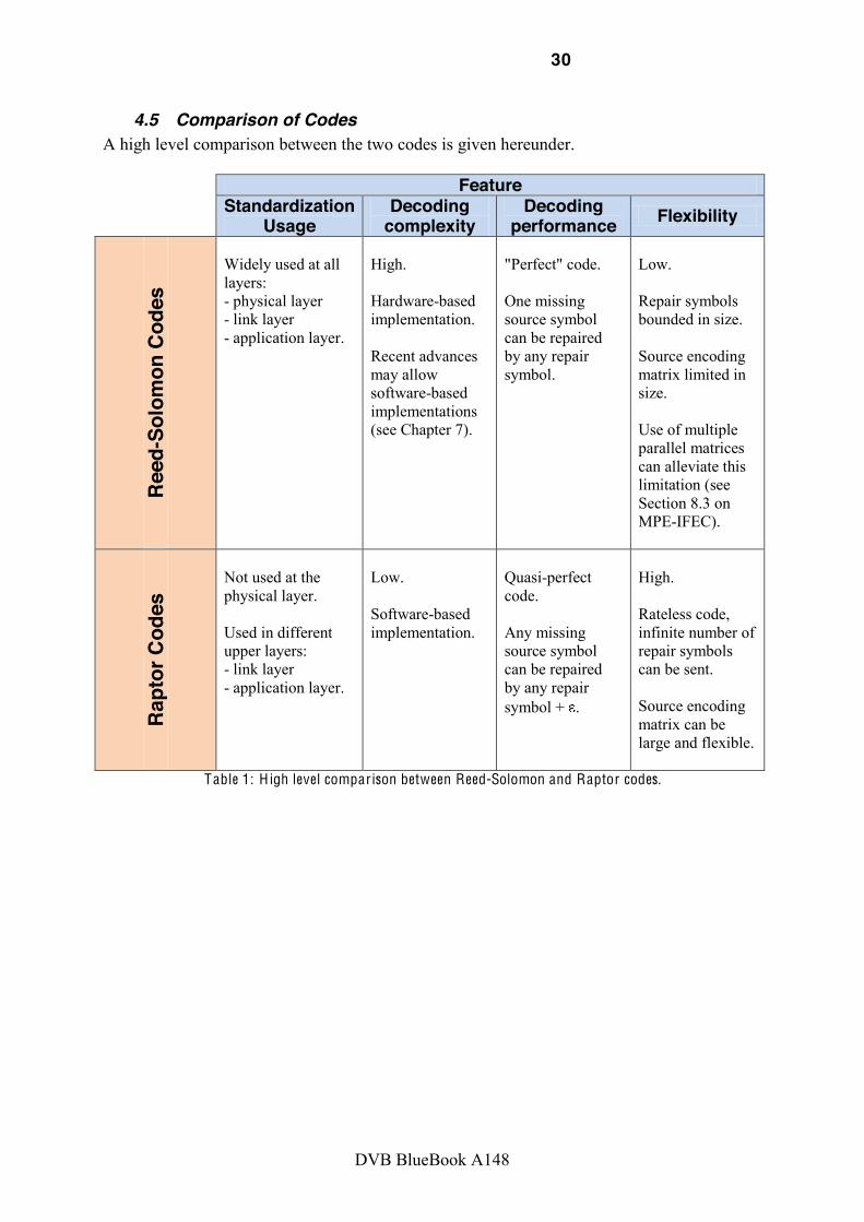
4.5 Comparison of Codes A high level comparison between the two codes is given hereunder.
Feature
Standardization Usage
Decoding complexity
Decoding performance Flexibility
Reed
-Sol
omon
Cod
es
Widely used at all layers: - physical layer - link layer - application layer.
High. Hardware-based implementation. Recent advances may allow software-based implementations (see Chapter 7).
"Perfect" code. One missing source symbol can be repaired by any repair symbol.
Low. Repair symbols bounded in size. Source encoding matrix limited in size. Use of multiple parallel matrices can alleviate this limitation (see Section 8.3 on MPE-IFEC).
Rapt
or C
odes
Not used at the physical layer. Used in different upper layers: - link layer - application layer.
Low. Software-based implementation.
Quasi-perfect code. Any missing source symbol can be repaired by any repair symbol + .
High. Rateless code, infinite number of repair symbols can be sent. Source encoding matrix can be large and flexible.
Table 1: H igh level comparison between Reed-Solomon and Raptor codes.

31
DVB BlueBook A148
5 Basic Design Considerations
5.1 UL-FEC Database In this section, we have gathered a database on UL-FEC summarizing main aspects to be taken into account while using and designing upper layer FEC. We distinguish between
5.1.1 Exogenous Aspects Exogenous aspects are presented in Figure 11 and are comprised of:
- the physical medium, mainly the DVB generation (1st or 2nd), xDSL;
- the system environment: typical systems include fixed receivers, transportable, mobile, portable or handset receivers;
- the existing applicable standards.

F igure 11: Exogenous parameters.

5.1.2 Internal Aspects On the internal side, we can analyze UL-FEC from following stand points:
Advantages and drawbacks.
Features.
Design. Each of these categories is detailed hereafter.
5.1.2.1 Advantages/Drawbacks Analysis
The following advantages can be listed:
Software implementation is possible: ! More memory options are possible using host memory.
! The solution can be developed at a later stage with short design phases when chipset needs long design phases.
De-correlation between physical and upper layer ! Enables advanced processing interacting with the video codec layers without
impacting on the physical layers.
! R .
! Makes a better usage of the bandwidth.
! Enables a fine per-service protection.
In principle it is possible to provide service-specific FEC at both the link (integrated within the MPE and GSE protocols) and the application layers, although AL-FEC is in general more suitable for providing different protection levels to different streams within a single service. The main benefits of AL-FEC are that it can recover from packet losses of all underlying layers and protocols, providing end-to-end error recovery, and that no standardization or modification is required below the application layer. AL-FEC is very beneficial for example for file delivery with FLUTE in IP-based networks, as a single FEC code word can be applied over the entire file, such that a very long time interleaving up to minutes, hours or even days can be applied. In this case AL-FEC is flexible and efficient, as it can be optimized to the service-specific FEC needs.
The following drawbacks can be listed:
Distributes FEC among several layers: this makes fine-tuning more difficult and performance worse than with a unique layer solution.
Also testing and integration may appear more complex.

F igure 12: U L-F E C advantage versus drawbacks analysis.

5.1.2.2 Features The following features can be listed:
Quality of service: UL-FEC can provide differentiated quality in addition to physical layer.
Interleaver: physical protection can be extended.
Zapping time: fast zapping may or may not be provided.
Service: different types of services can be supported, from TV to file delivery and internet access.
The maximum time interleaving and the error correction capability of the upper layer FEC code will be mainly determined by:
FEC and interleaving at the physical layer.
Error patterns characteristic in the system under study.
Quality of service requirements, in particular delay constraints and target residual error rate.
For example, the DVB-T physical layer FEC provides a very short time interleaving of few milliseconds, and hence it is very vulnerable to fast fading under mobility conditions and impulse noise. To cope with these impairments in DVB-H, a time interleaving in the order of hundreds of milliseconds (burst duration) is added.
Higher layers also generally imply larger delays. In this sense, LL-FEC may be preferable than AL-FEC for streaming services. However, it should be pointed out that it is necessary to provide the link layer with information regarding the random access points of the multimedia streams.
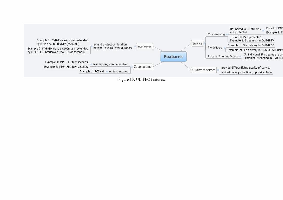
Figure 13: UL-FEC features.

5.1.2.3 U L-F E C Design The following design criteria can be listed:
Layer: UL-FEC can be implemented at different layers such as below IP (link) and above IP (application).
Implementation: different implementations are possible (full hardware, full software and mixed).
F E C codes: different codes can be used (Reed-Solomon, XOR, Raptor).
Interleaver: different types of interleavers can be used (block, convolutional).
Signaling: different types of signaling can be used (real-time and non real-time).
Regarding the different layers where the upper layer FEC code can be introduced (link or application layer, if the FEC scheme is implemented below or above the IP layer respectively), it should be taken into account the fact that errors propagate in the upper layers of the protocol stack, as the mapping of packets data units is in general not aligned. Nevertheless, under a correct design the error correction capability performance should be practically identical despite the layer employed, and only signaling aspects may differ. In any case, reliable erasure information should be provided at the layer where the upper layer FEC code is to be introduced.
When deciding which FEC scheme to adopt, the main performance metrics to be considered are the reception overhead and failure probability (i.e., how close the code performs from an ideal erasure code), and the memory requirement at the terminals.
From a system implementation point of view, the possibility of a full software implementation at the receivers that only require a small amount of fast memory for decoding may be especially beneficial for receivers with limited processing capabilities such as handhelds, as well as to introduce upper layer FEC in already operative systems. Otherwise dedicated hardware will be required at the terminals.

F igure 14:U L-F E C design analysis.

5.1.2.4 Other Considerations If the FEC is not intended to be mandatory at the receivers it should be introduced in a backwards-compatible way for terminals without upper layer FEC decoding capabilities. Hence, the original (legacy) multimedia stream cannot be modified, and a systematic FEC erasure code that keeps the original source packets should be adopted. Its signaling should also be performed in a transparent way for legacy terminals, e.g., by using reserved-for-future-use fields in existing standards.

40
DVB BlueBook A148
5.2 UL-FEC Cookbook The cookbook presents in the form of a decision tree for any UL-FEC user.
In the following, we distinguish between the existing designs where the decision tree is only a way to select the appropriate technique, and the new cases where the decision tree is helping making appropriate new design choices.
F igure 15: U L-F E C cookbook root decision.
For each technique, the decision tree are described in the following, combining a number of service, system and feature oriented questions.
For DVB1.0, all tree branches lead to existing leafs. In addition, a number of questions can be raised while parsing the DVB1.0 decision tree in conjunction with the following question:
-layer FEC to existing physical layer specifications
- shall long interleaver link protection such as MPE-IFEC be implemented on DVB-H ?
- shall SVC layar-aware FEC be implemented on existing DVB-SH and DVB-H ?
On the contrary, for DVB2.0, some leafs do not correspond to existing standards. Therefore, in addition to the questions raised for DVB1.0, we face additional questions that are reported in the future work section:
- shall existing techniques such as MPE-IFEC be ported to new environments such as DVB-T2 and NGH ?
- shall file delivery specifications like CDS used in IPTV be considered for NGH system ?
Therefore to illustrate in the following figures the possible choices, we have identified 3 possible options for each leaf:
- Standard: this leaf is already addressed by an existing specification; there is no choice but implementing it; for instance UL-FEC in DVB-H is mandated to be MPE-FEC;
41
DVB BlueBook A148
- Recommendation: the leaf is not already addressed by any specification but there is no specific technical work; for instance DVB-H could adopt MPE-IFEC immediately;
- Suggestion: the leaf is not addressed by any specification and there is some technical work to be done in order to address it: for instance, SVC-aware layer would need specific work to be completed before being applied.

F igure 16: U L-F E C cookbook for D V B 1.0.

43
DVB BlueBook A148
F igure 17: U L-F E C cookbook for D V B 2.0.

6 Summary
6.1 Main outcomes The most important conclusions of the work performed by the TM-ULFEC task force can be summarized as follows:
UL-FEC has been widely used in DVB 1.0 systems for a variety of reasons: - Extending physical layer capabilities to provide support of additional features
that were not considered at the beginning. For example, mobility support for the DVB-T physical layer with MPE-FEC (DVB-H).
- Increasing robustness over error prone channels (due to noise, interference, mobile radio channel impairments, etc.). For example, AL-FEC for IPTV, or MPE-IFEC in DVB-SH.
- Enabling deployment scenarios that would not be possible at reasonable economic conditions otherwise. For example, large file download with AL-FEC.
As the needs were progressively covered, an informal toolbox has been defined. Three main aspects defined within the toolbox (see figure below):
- FEC code: there is mainly a choice between Reed-Solomon and Raptor codes. - Encapsulation protocol: mainly MPE, TS and GSE are used. - Interleaving profile: short and long. For streaming delivery long profiles are
jointly used with fast zapping techniques.
O//C4-(-?-+
O',)-*
4"-*)
L-+F
89:
>+)/*
(/'D/*
9+&',
$@(')%-+
;!9
14A.<49
F igure 18: D V B U L-F E C Informal Toolbox
Outcome 1: Recent experience during the D V B-R CS+M standardization process has shown that this toolbox can be reused quite generically . Therefore, D V B 2.0 systems shall be aligned with the D V B U L-F E C toolbox. New U L-F E C schemes shall be required to motivate in detail the need for new solutions.
As technology improves, more advanced UL-FEC solutions may be implemented in DVB 1.0 and DVB 2.0 systems. Specific innovations may at some point become mature-enough for potential inclusion in the specifications.
45
DVB BlueBook A148
Outcome 2: While the formalized toolbox is available for any technique in D V B , it is up to each working group to decide if and when elements of the toolbox shall be used. This is especially true for D V B 1.0 systems due to legacy reasons. Nevertheless, it should be taken into account that new U L-F E C schemes may improve the overall system performance.
For example, the MPE-IFEC, although originally designed for the DVB-SH standard, can be used to improve the robustness of DVB-H transmissions for streaming services, see Section 8.4. MPE-IFEC can be also used to increase the time interleaving in DVB-T2 to improve the reception of mobile services, see [BAQ01].
Outcome 3: On-going innovations in F E C , video coding, and content delivery protocols suggest an update of the D V B U L-F E C bluebook on a regular basis.
Although the UL-FEC domain has been quite extensively scouted in the last years, given the variety of specifications, it is still today a hot topic of research. Most representative examples are:
Software-based Reed Solomon decoding implementations. Novel Scalable Video Coding layer-aware FEC schemes. Cross-layer optimization of new DVB 2.0 waveforms, such as DVB-T2, considering
upper layer FEC schemes and SVC.
The bluebook should be also updated to clarify the upper layer FEC schemes within the different content delivery protocols available in the market (e.g., CDS and CDP). As convergence between fixed and mobile world is happening, it is not clear which one should be selected for the new systems.
The proposed updated procedure for the DVB UL-FEC bluebook is summarized in the figure below.

46
DVB BlueBook A148
GL=89:.P(@/.Q--K.O/(/'$/.+RS
8-*?'(%T/C )--(Q-UL%$).-I.,-)/+)%'(
J-*K %)/?$
L'@+&" -I.$/(/&)/CJ-*K %)/?
%+4,/&%I%&
V-*K%+F F*-@,$
GL=89:.P(@/.Q--K.O/(/'$/.+
8-*?'(%T/C )--(Q-UL%$).-I.,-)/+)%'(
J-*K %)/?$
L'@+&" -I.$/(/&)/CJ-*K %)/?
%+4,/&%I%&
V-*K%+F F*-@,$
1%?/
>+&(@$%-+
.%+.)"/.)--(Q-
U
1W 1W.R.*/I*/$"X)%?/
F igure 19: D V B U L-F E C Bluebook Update Procedure
6.2 Known limitations The performance of any upper-layer FEC strongly depends on the performance of the lower layers. The current version of the bluebook does not take any cross-layer optimization approaches into account. This aspect shall be considered for the next versions of the bluebook. Additionally some simulation activities were not mature enough for inclusion in the blue book (see table in 9.1 for the coverage overview).
6.3 Potential future work for DVB on Upper Layer FEC The current work items list is a proposition to address in dedicated working groups. The way these items are actually addressed (CBMS, GBS, other working group) is not considered.
6.3.1 Software-based FEC using Reed-Solomon codes Up to now, only the Raptor code was considered as a potential candidate for enabling software decoding. Recent research in the field of code theory has demonstrated that Reed-Solomon codes are currently largely underexploited. Reed-Solomon codes can also be processed at the binary image, where their decoding can be envisaged in software with important performance improvements.
An analysis of the encoding and decoding speed, as well as the encoding and decoding memory requirements should be conducted. However, one could expect the minimization of complexity when applied with the binary image of RS code if referred to the following reference [CR08]. In fact, the sum-product algorithm coupled with a Gaussian elimination is analyzed in this paper. The authors have shown that this decoding strategy!"#$%!&'!#()*#+)%!#,!-)#$,! &')! &*.)*! &/! 0#+'1,2.)! /#$,)*! ,3#'! ,3)! *)/)*)'4)! 5)).67&-&0&'! 4&.)4! 8*&8&$).! 1'!951:;<=>!?)!'&,14)!,3#,!,3)!$2068*&.24,!#-+&*1,30!#'.!,3)!@#2$$1#'!)-101'#,1&'!#*)!#-$&!2$).!
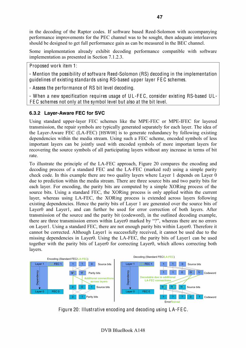
47
DVB BlueBook A148
1'! ,3)! .)4&.1'+! &/! ,3)! 5#8,&*! 4&.)$>! A/! $&/,"#*)! B#$).!5)).67&-&0&'!"1,3! #44&08#'C1'+!8)*/&*0#'4)!108*&()0)',$!/&*!,3)!DEF!43#'')-!"#$!,&!B)!$&2+3,%!,3)'!#.)G2#,)!1',)*-)#()*$!$3&2-.!B)!.)$1+').!,&!+),!/2--!8)*/&*0#'4)!+#1'!#$!4#'!B)!0)#$2*).!1'!,3)!HEF!43#'')->!
7&0)! 108-)0)',#,1&'! #-*)#.C! )I31B1,! .)4&.1'+! 8)*/&*0#'4)! 4&08#,1B-)! "1,3! $&/,"#*)!108-)0)',#,1&'!#$!8*)$)',).!1'!7)4,1&'!<>J>K>L>
Proposed work item 1:
- M ention the possibility of software Reed-Solomon (RS) decoding in the implementation guidelines of existing standards using RS-based upper layer F E C schemes.
- Assess the performance of RS bit level decoding.
- When a new specification requires usage of U L-F E C , consider existing RS-based U L-F E C schemes not only at the symbol level but also at the bit level .
6.3.2 Layer-Aware FEC for SVC Using standard upper-layer FEC schemes like the MPE-FEC or MPE-IFEC for layered transmission, the repair symbols are typically generated separately for each layer. The idea of the Layer-Aware FEC (LA-FEC) [HSW08] is to generate redundancy by following existing dependencies within the media stream. Using such a FEC scheme, encoded symbols of less important layers can be jointly used with encoded symbols of more important layers for recovering the source symbols of all participating layers without any increase in terms of bit rate.
To illustrate the principle of the LA-FEC approach, Figure 20 compares the encoding and decoding process of a standard FEC and the LA-FEC (marked red) using a simple parity check code. In this example there are two quality layers where Layer 1 depends on Layer 0 due to prediction within the media stream. There are three source bits and two parity bits for each layer. For encoding, the parity bits are computed by a simple XORing process of the source bits. Using a standard FEC, the XORing process is only applied within the current layer, whereas using LA-FEC, the XORing process is extended across layers following existing dependencies. Hence the parity bits of Layer 1 are generated over the source bits of Layer0 and Layer1, and can further be used for error correction of both layers. After transmission of the source and the parity bit (codeword), in the outlined decoding example,
on Layer1. Using a standard FEC, there are not enough parity bits within Layer0. Therefore it cannot be corrected. Although Layer1 is successfully received, it cannot be used due to the missing dependencies in Layer0. Using the LA-FEC, the parity bits of Layer1 can be used together with the parity bits of Layer0 for correcting Layer0, which allows correcting both layers.
Layer 0
Layer 1 1
0/1 1/1
1 0
0
0 1
0 1
LA-FEC 1
Dep
ende
ncy
FEC 0
Additional connections across layers
Layer 0
Layer 1 1
1 1
1 0
?/0
? ?
?/0 ?/1
LA-FEC 1
Dep
ende
ncy
FEC 0
Decodable due to additional LA-FEC connections
Encoding (Standard FEC/LA-FEC)Decoding (Standard FEC/LA-FEC)
Source bits
Parity bits
Source bits
Parity bits
Source bits
Source bits
0 0/1 1/1
? 0 1
Codeword
Codeword
Error/Solved F igure 20: I llustrative encoding and decoding using L A-F E C .

48
DVB BlueBook A148
The additional dependency introduced by the LA-FEC does not show an impact on the performance of the transmission as shown in the simulation results in Annex 9. This is due to the cross layer FEC follows existing dependencies within the media stream and the enhancement layer cannot be used without the base layer. Such an LA-FEC scheme can be easily applied to existing FECs as shown for the Raptor code in Annex 10, where the Raptor coding algorithm is modified in such a way that all Raptor symbols of dependent layers follow existing dependencies within the media stream in the same way as illustrated in Figure 20. Such a Layer-Aware Raptor could also be applied to the MPE-iFEC solution. Since Raptor code is typically implemented in software, the proposed extension in Annex 10 could be applied to existing implementations via a simple software update.
Note that the LA-FEC approach can not only be applied to SVC but also to other signals with a hierarchical dependency structure as e.g. 3D video, MVC, surround sound.
Proposed work item 2:
- Include SV C Layer-Aware F E C usage in the relevant specifications.
- Introduce this technique in the U L-F E C D V B toolbox.
6.3.3 MPE-IFEC for other Systems (DVB-H, DVB-T2, DVB-NGH) As mentioned before, the use of MPE-IFEC for streaming delivery can be beneficial not only for DVB-SH. In DVB-H for example, MPE-IFEC can be used to provide a multi-burst protection of the transmission for streaming services, enhancing the robustness of the transmission compared to the conventional intra-burst MPE-FEC, see Section 8.4 and references therein. Some illustrative results are presented in Section 9.2.3. Another example is the second generation DVB-T2 standard. Although it primarily targets the transmission to fixed and portable receivers, its enhanced robustness compared to DVB-T, and high degree of flexibility may allow the reception in mobile environments as well. DVB-T2 provides a per-service configuration of the transmission parameters at the physical layer that makes possible to particularize the level of robustness or power saving on a service-by-service basis. This characteristic allows the transmission of services aimed to different user cases, like fixed, portable or mobile, in the same frequency channel. However, there are some limitations in DVB-T2 for the provision of mobile services that could be solved with a link layer FEC code such as MPE-IFEC. In DVB-T2 the maximum amount of memory that can be interleaved by the receivers is very limited. The maximum number of cells that can be stored for interleaving is 2^19 + 2^15 per service. This number stands for every modulation and code rate included in DVB-T2. This means that the maximum time interleaving depth that can be provided by the physical layer depends on the service bit rate along with the modulation and code rate configured for that service. For instance, if a service of 1 Mbps is transmitted in a DVB-T2 system with a modulation of 16QAM and a code rate of 1/2, the maximum time interleaving depth that can be achieved by the physical layer is limited to approximately 1 second. This value, that may prove sufficient for fast fading, may be not enough to protect the service against shadowing. Services with higher bit rates result in time interleaving depths even more limited and hence, the maximum time interleaving depth that can be provided by the physical layer of DVB-T2 represents an important issue in mobile reception. This problem could be efficiently solved using a link layer FEC with long interleaving depths as presented in Section E rror! Reference source not found.. Finally, since DVB-NGH is also assumed to be developed on top of DVB-T2, MPE-IFEC could also be considered.

49
DVB BlueBook A148
Proposed work item 3: - Formalize the usage of MPE-I F E C for other systems than D V B-SH . - This interest of this usage would be demonstrated in the U L-F E C bluebook document and/or in the specific working group. - Then, it shall be included in the specific implementation guidelines.

50
DVB BlueBook A148
7 Annex A Details on Reed-Solomon and Raptor Codes
7.1 Reed-Solomon Codes
7.1.1 Code Performance
7.1.1.1 Symbol-level RS Codes Reed-Solomon codes are known to have an optimal erasure recovery capacity. They can correct as many lost packets (erasures) as the number of parity packets transmitted, having thus zero reception overhead and no failure probability. In this sense they are thus ideal, but only within the tight parameter restrictions for k and n.
7.1.1.2 Binary RS Codes It is shown in [ASR09] that the binary Reed Solomon codes are good codes with an asymptotically good minimum distance that is always greater than the minimum distance of the symbol-level Reed Solomon. In addition, it has been proved that as the code length and the field size grow, the average binary Reed Solomon behaves as a random code of the same dimensions.
If compared to the symbol-level Berlekamp Massey Algorithm, implemented usually in a dedicated chipset, the bit-level adaptive parity check-sum product decoding in the case of the RS (31, 25) RS and the RS (255,191) (code of DVB-SH standard) outperforms and recovers within 90% more erasures, see Figure 21. These results show that the symbol-level bounded distance decoding algorithms widely used in practical systems, do not fully exploit the error correction capability of the RS codes.
F igure 21: Performance of RS code (255,191) over B E C [ASR09].
In addition to theses good properties, the binary RS codes decoded with ADP-sum product algorithm approaches the sphere packing bound within 2%. It is shown, as is proven theoretically in [EKME04], that as the code length and the field size grow, the binary images

51
DVB BlueBook A148
of Reed Solomon behave as a random code of the same dimensions, and that the Generalized Reed Solomon codes are good codes, with an asymptotically good minimum distance.
7.1.2 Complexity
7.1.2.1 Working in finite fields on hard information based decoding Reed-Solomon codes present a very high encoding and decoding complexity, which is directly proportional to the block length and the rate of the parity data generated. In particular the workload grows as the product of these two quantities. As a consequence only short to moderate block lengths are feasible without requiring dedicated hardware. The decoding of Reed-Solomon codes is prohibitively complex for a software implementation, and hence they are typically also implemented on dedicated hardware to support their complex algebraic decoding dealing with polynomials in finite fields.
To overcome this practical inconvenient, some software-based implementations have been proposed in [Riz97]. However, these approaches are still demanding in CPU processing as they are dealing with finite fields operations.
7.1.2.2 Working in non finite fields on soft Information base decoding In the special case of the BEC, which is analyzed in [ASR09] the values of the initial Log Likelihood Ratios or observations are reduced to three values {- . Hence the ADP algorithm eliminates stopping sets, only within the sub graph containing erasures. It is find out in [ASR09] that the algorithm does not require more than one iteration to converge or fail. This is making the complexity decreasing in comparison with the original algorithm performing multiple Gaussian eliminations. The channel is modeled as a virtual binary erasure channel. The simulated codes are chosen differently, (7,5), (31,25) and (255, 191).
7.1.2.3 Software decoding 7&0)! 108-)0)',#,1&'! #-*)#.C! )I31B1,! .)4&.1'+! 8)*/&*0#'4)! 4&08#,1B-)! "1,3! $&/,"#*)!108-)0)',#,1&'>!7243!#'!108-)0)',#,1&'!/&42$)$!&'!)*#$2*)!*)4&()*C!#'.!'&,!&'!,3)!MEF>!N!8)*/&*0#'4)! B)'430#*O! "1,3! #'! &8)'! $&2*4)! 57! .)4&.1'+! P3,,8QRR""">O#;G>'),R4&.)R/)4S!0#.)!&'!DELL Vostro 1500 Linux consists in measuring UC time for decoding RS matrices of 191 data columns and 64 FEC columns and different rows (256,512,768,1024) inside which a various number of data columns (10,20,30,40,50,60) are erroneous. Results are given below:
- Average case: ! Old implementation:175 ms per matrix; ! New: 7.11 ms per matrix.
- Worst case (1024 rows and 60 erroneous columns): ! Old implementation: 388 ms ! New implementation: 20 ms

52
DVB BlueBook A148
Rs decoding performance
1
10
100
1000
0 10 20 30 40 50 60
Nof Errored Cols
Tim
e to
dec
ode
(ms)
256r-Old
256r-New
512r-Old
512r-New
768r-Old
768r-New
1024r-Old
1024r-New
F igure 22: RS decoding benchmark .
Based on the worst case, an estimation of the time required to decode a single DVB service of 400 kbps is approximated to 5 ms of UC time. This time would be around 20 ms on an ARM@600MHz. Therefore software Reed-Solomon decoding is now possible inside a terminal, even a full TS could be decoded.
7.1.3 Decoding Algorithms
7.1.3.1 Symbol-L evel Approach Reed-Solomon (RS) codes are one of the most popular error correction codes in many state-of-the-art communication and recording systems. In most of these existing systems, RS codes are decoded via an algebraic hard decision decoding (HDD) algorithm which does not fully exploit the error correction capability of the code. The reference HDD algorithm is based on Berlekamp-Massey algorithm and can be divided in 4 steps:
1) The first part is the syndromes computation, which consists in evaluating the values of 2t polynomials each of length n. The syndromes can be viewed itself as a polynomial of degree 2t which only depends on the error pattern. The complexity of this syndromes evaluation is (2t) n MACGF, where MACGF is the cost of a Multiplier-Accumulator in the Galois Field GF(256). The complexity of this MACGF itself depends on the fact that dedicated hardware exists or not.
2) The second part is the evaluation of the error-locator polynomial that is a polynomial of which the roots give the error positions. This polynomial is usually computed by using the Berlekamp-Massey algorithm or the Euclidean algorithm. However in the case of MPE-(I)FEC the error position are known so this polynomial can be directly evaluated. The cost of this computation is about 0.5(2t)2 MACGF in the worst case (2t errors).
3) The third part is the computation of the error-evaluator polynomial. This can be done by multiplying Syndrome polynomial and error-locator polynomial modulo x2t the complexity of this operation is also 0.5(2t)2 MACGF.
4) This fourth part is the computation of the error itself by using the Forney algorithm. This consists in the division of the error evaluator polynomial by the derivative of the error locator polynomial. The complexity is about n (2t+t) MACGF + 2t INVGF,

53
DVB BlueBook A148
where INVGF is an inversion in the Galois Field GF(256). If an exponentiation operator is available the complexity could be made independent of n here.
However recent research has open more advanced ways for decoding Reed-Solomon in the binary image of the Galois field.
7.1.3.2 Bit L evel Approach In order to obtain low complexity software based RS decoding, the research effort focuses the soft information based decoders. In fact, when soft information about the channel output is available, HDD can incur a significant performance loss compared to optimal soft decision decoding. Many efficient suboptimal soft decision decoding (SDD) algorithms have been developed in this sense. The authors in [For96], [Cha72], [TLF+00] propose to assist HDD by using the reliability value. The authors in [VB91] and [PV02] propose to take advantage of the structure of RS codes at the bit-level to reduce the complexity. Some other authors, [HL03] and [FV04], apply decoding algorithms for general linear block codes to RS soft-decision decoding. More recently, iterative techniques have also been proposed for RS soft-decision decoding ([Ung03], [Yed04], [JN04], [JN06]).
Most of the known iterative decoding methods for RS codes are using its binary image expansion, i.e., it is equivalent to the general problem of decoding binary linear block codes. It is known, [YCF02], that the performance of iterative decoding will be different with the choice of parity check matrix even if the code is the same.
Therefore, the binary version1 of RS codes should be sparse to make possible its decoding via an iterative algorithm.
As the bi-partite graph corresponding to the binary parity check matrix Hb is too dense to support a message passing algorithm, the adaptive Parity Check Matrix (ADP) based sum-product algorithm, proposed for the first time in [JN06] for decoding iteratively binary Reed Solomon codes over AWGN and Rayleigh fading channels, circumvents this inconvenient.
1 Binary expansion of RS codes: RS codes can be viewed as non-binary Bose-Chaudhuri and Hocquenghem (BCH) codes. The parity-check matrix sH of a ),( KNRS code over mGF 2 with a minimum distance 1min KNd , can be represented by:
KNNKN
N
N
sH
1
122
1
1
11
Where is a primitive element in mGF 2 .
sH has an equivalent binary image expansion bH where bH is an nkn binary parity check matrix
with mKkandmNn . Therefore, RS code can be viewed as a binary linear block code.

54
DVB BlueBook A148
7.2 Raptor Codes
7.2.1 Code Performance Raptor codes achieve very close to ideal performance for a wide range of parameters and only slightly more than k symbols are needed to recover the source data independent of the packet loss characteristics (i.e., there is no sensitivity to loss). The reception overhead is a statistical value, and usually a fixed value is considered such that the reconstruction probability is very high. The small inefficiency of the Raptor code can be modeled by the following equation [SSW+08]:
P
f(r , k ) 1 if r k
0.85 0.567 r k if r k
Where Pf denotes the failure probability of the code with k source symbols if r symbols have been received. While an ideal fountain code would decode with zero failure probability for m = k, the failure for Raptor code is still about 85%. However, the failure probability decreases exponentially with an increasing number of received symbols. The increase is so fast, that for only 12 additional symbols the failure probability is 0.1% and for 24 additional symbols the failure probability is 0.0001%. Note that what matters is the absolute number of received symbols, not their fraction compared to the number of source symbols. Thus the reception overhead decreases with increasing k. Based on the function Pf(r, k), the average reception overhead can be expressed as a function of k as [SSW+08]:
0.85( )
(1 0.567)k
k Which can be approximated by 2/k. Hence, the number of additional symbols is on average 2, independent of the value of k. Therefore, for typical source block sizes of 1000, the average reception overhead is at most 0.2%.
7.2.2 Complexity Raptor codes are very attractive in terms of encoding and decoding complexity, as they present a complexity low enough to allow for a full software implementation. Furthermore the complexity is linear with the source block size and the rate of parity data generated. Each encoding symbol can be generated on the fly independent of all other encoding symbols, and the average cost of generating each encoding symbol is the same, approximately 7.5 packet XORs. The decoding workload is approximately 10 packet XORs independent of the particular encoding symbols used to reconstruct it.
The computational complexity of Raptor codes was evaluated during the 3GPP MBMS standardization effort. For example, on a 206 MHz ARM platform, decoding speeds of more than 25 Mbps can be supported.
7.2.3 Decoding Algorithms This section describes an efficient decoding algorithm for the Raptor codes. Note that each received encoding symbol can be considered as the value of an equation amongst the intermediate symbols. From these simultaneous equations, and the known pre-coding relationships amongst the intermediate symbols, any algorithm for solving simultaneous equations can successfully decode the intermediate symbols and hence the source symbols. However, the algorithm chosen has a major effect on the computational efficiency of the decoding.

55
DVB BlueBook A148
F igure 23 Raptor Decoding!
Raptor codes can be decoded in a variety of ways, the basic idea is to obtain the source symbols from a set of received encoding symbols (see Figure 23). The conceptually simplest decoder sets up a system of linear equations and solves the system using Gaussian elimination. The system to set up has the following shape: suppose that the code has a check matrix H with m columns and m k rows. The input symbols can be recovered by solving the system of linear equations. One can employ the Gaussian elimination algorithm to decode. This decoder is optimal as far as the success of the recovery procedure is concerned: decoding (by means of any algorithm) fails if and only if the Gaussian elimination decoder fails. However, the running time of this decoder is prohibitively large. A different decoder with much lower complexity operates in the same manner as a greedy algorithm for decoding LT-codes. The greedy decoding algorithm is a modification of the one presented in [O1] and proceeds in rounds. At each round, we search for an output symbol of degree one, and copy its value into the value of its unique neighbor among the source symbols. We then XOR the value of the newly found source symbol into all the neighbors of the source symbol among the output symbols, and delete all edges emanating from the source symbol. We continue the procedure until we cannot find an output symbol of degree one. If at this point not all the source symbols are recovered, then a decoding error is declared. In applications it is often advantageous to not perform the XOR operations in this algorithm immediately. Inwhich stores the order in which the XORs are performed. The superior computational performance of this greedy decoding algorithm comes at the expense of large overheads for small source block sizes k. This can be explained by the fact that for small k the variance of the decoding process is too large compared to k, and hence decoding fails more often than for large k. To remedy this situation, a different decoding algorithm has been devised called inactivation decoder (see also [O2] for further details). This decoder combines the optimality of Gaussian elimination with the efficiency of the greedy algorithm. Inactivation decoding is useful in conjunction with the scheduling process. The basic idea of inactivation decoding is to declare an input symbol as inactivated whenever the greedy algorithm fails to find an output symbol (dynamic or static) of weight 1. As far as the algorithm is concerned, the inactivated symbol is treated as decoded, and the decoding process continues. The values of the inactivated input symbols are recovered at the end using Gaussian elimination on a matrix in which the number of rows and columns are roughly equal to the number of inactivations. One can view Gaussian elimination as a special case of inactivation decoding in which inactivation is done at every

56
DVB BlueBook A148
step. Successful decoding via the greedy algorithm is also a special case: here the number of inactivations is zero. If the number of inactivations is small, then the performance of the algorithm does not differ too much from that of the greedy algorithm; at the same time, it is easy to show that the algorithm is optimal in the same sense as Gaussian elimination. In the following we provide a brief overview on the inactivation decoding process. Figure 24 shows the preparation of inactivation decoding Suppose k encoding symbols are used to decode (generally at least k are needed). Unknown before decoding are the C[*]symbols, l in total: k source symbols and s LDPC symbols and h HDPC symbols. Known are the D[*] symbols, l in total: s+h relation symbols (all zeroes symbols) and n encoding symbols. The matrix A describes how D[*] was generated from C[*].
F igure 24 Inactivation Decoding Preparation
The objective of the decoding is to transform matrix A into identity. For this, columns and rows in can be swapped, requiring also a swapping of the corresponding entries in C and D. Furthermore, rows in A can be added, resulting in the sum function on the corresponding entries in D. Once A has become the identity matrix, the D will contain the source, LDPC and HDPC symbols in the order dictated by C. The process of producing the identity matrix is show in Figure 25 with:
The sub-matrix I defined by the intersection of the first I rows and first i columns. This is the identity matrix at the end of each step in the phase.
The sub-matrix U defined by the intersection of all the rows and the last u columns. The sub-matrix V formed by the intersection of all but the first i columns and the last u
columns and all but the first I rows. Two all-zero matrices.
Generally V grows faster than U. The phase ends successfully when V and the all-zeroes sub-matrix above V have disappeared and A consists of I, the all zeroes sub-matrix below I, and U. The phase ends unsuccessfully in decoding failure if, at some step before V disappears, there is no non-zero row in V to choose in that step. Whenever there are non-zero rows in V,
r the row is chosen in this step the first row of A that intersects V is exchanged with the chosen row so that the chosen row is the first row that intersects V. The columns of A among those that intersect V are reordered so that one of the r ones in the chosen row appears in the first column of V and so that the remainingr-1 ones appear in the last columns of V. Then, the chosen row is exclusive-ORed into all the other rows of A below the chosen row that have a one in the first column of V. Finally, i is incremented by 1 and u is incremented by r-1, which completes the step.

57
DVB BlueBook A148
The objective at the end of phase 1 is that i is as large as possible and u is as small as possible.
F igure 25 Inactivation Decoding phase 1
After phase Figure 26transformed into an identity matrix using Gaussian elimination to either determine that its rank is less than u (decoding failure) or to convert it into a matrix where the first u rows is the identity matrix (success of the second phase). After this phase, A has L rows and L columns. After the second phase, the only portion of A that needs to be zeroed out to finish converting A into the L by L identity matrix is i of the sub-matrix generally much larger than the number of columns u .
F igure 26 Inactivation Decoding phase 2 and phase 3
The inactivation decoding analysis shows that in phase 1, the symbol operations to convert V to I is same as LT decoding (typically by the use of a greedy belief propagation). The symbol operations on U are slightly more complex, but number of operations is still bounded because the code is designed to keep u small. In phases 2 and 3 symbol operations on U are more complex but u stays small due to LT degree distribution, LDPC symbols are also amenable to LT decoding and selected late in the transform process of phase 1. HDPC symbols are not amenable to LT decoding, but they can be solved efficiently using the Gaussian elimination
Further optimizations and variants of the inactivation decoding can lead to extremely fast decoding of Raptor codes, possibly adapted to software and/or hardware constraints.

58
DVB BlueBook A148
8 Annex B Detailed Examples of Upper Layer FEC
8.1 MPE-FEC for DVB-H Streaming Services
8.1.1 Concept DVB-H inherits the DVB-T physical layer, which was primarily designed for fixed rooftop reception with a very short interleaving depth (up to two OFDM symbols, of a maximum duration of 1.12 ms) [28]. Hence, it is very vulnerable against fast fading and impulse interference. In order to compensate for the performance degradations due to fast fading under mobility conditions and to improve the tolerance to impulse interference, and optional intra-burst FEC mechanism at the link layer called MPE-FEC was adopted in DVB-H [8].
When MPE-FEC is employed in DVB-H, the IP information is encoded burst by burst with a Reed-Solomon (RS) code as shown in Figure 27. With MPE-FEC it is possible to recover from bursts partially received. The maximum percentage of errors per burst that can be corrected is proportional to the code rate. For example the code rate 3/4 can cope with up to 25% errors.
T ime-sliced bursts
Source Data
Parity Data
IP datagram bursts
Protection Period
MPE-F E C CR 3/4
CR)! 100%!
Burst correctly decoded
Burst partially decoded
Burst lost
Percentage of er rors?
Errors
MPE-F E C CR 3/4
> (1 CR)!
O riginal multimedia stream time
F igure 27: T ime-slicing and MPE-F E C concept in D V B-H .
MPE-FEC provides an effective time interleaving depth at the link layer equal to the burst duration (typical values 0.2-0.4 s), and it basically copes with fast fading in covered areas where static reception is possible, increasing the robustness of reception for mobile terminals such that the signal strength requirement becomes practically independent of the speed [FHST06]. It provides a similar mobile performance than a DVB-T receiver using 2 antennas diversity.
MPE-FEC can only cope with very small outage periods that represent a fraction of the burst duration, but it cannot recover from complete lost bursts. In this case the multimedia stream is interrupted until the next burst is received. Note that if the MPE-FEC decoder fails, only correctly received source IP packets will be available for playback. In order to recover from complete lost bursts, a multi-burst FEC scheme spanning several time-sliced bursts is required, see Section 8.4.
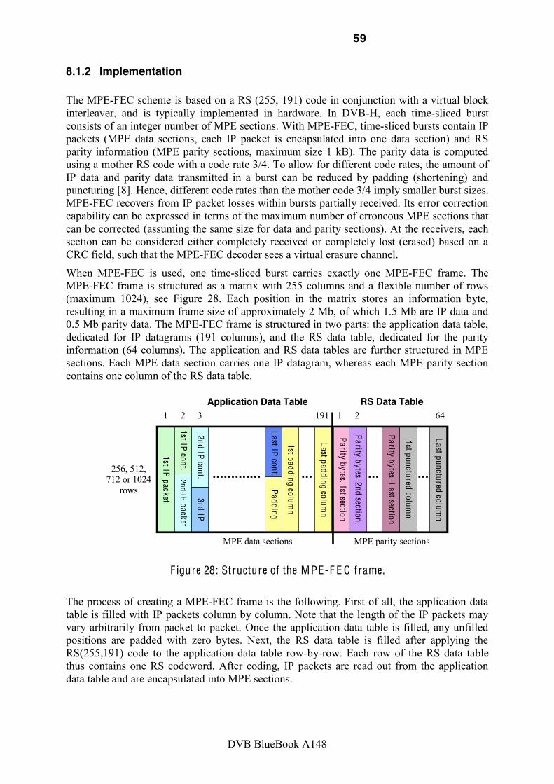
59
DVB BlueBook A148
8.1.2 Implementation !The MPE-FEC scheme is based on a RS (255, 191) code in conjunction with a virtual block interleaver, and is typically implemented in hardware. In DVB-H, each time-sliced burst consists of an integer number of MPE sections. With MPE-FEC, time-sliced bursts contain IP packets (MPE data sections, each IP packet is encapsulated into one data section) and RS parity information (MPE parity sections, maximum size 1 kB). The parity data is computed using a mother RS code with a code rate 3/4. To allow for different code rates, the amount of IP data and parity data transmitted in a burst can be reduced by padding (shortening) and puncturing [8]. Hence, different code rates than the mother code 3/4 imply smaller burst sizes. MPE-FEC recovers from IP packet losses within bursts partially received. Its error correction capability can be expressed in terms of the maximum number of erroneous MPE sections that can be corrected (assuming the same size for data and parity sections). At the receivers, each section can be considered either completely received or completely lost (erased) based on a CRC field, such that the MPE-FEC decoder sees a virtual erasure channel.
When MPE-FEC is used, one time-sliced burst carries exactly one MPE-FEC frame. The MPE-FEC frame is structured as a matrix with 255 columns and a flexible number of rows (maximum 1024), see Figure 28. Each position in the matrix stores an information byte, resulting in a maximum frame size of approximately 2 Mb, of which 1.5 Mb are IP data and 0.5 Mb parity data. The MPE-FEC frame is structured in two parts: the application data table, dedicated for IP datagrams (191 columns), and the RS data table, dedicated for the parity information (64 columns). The application and RS data tables are further structured in MPE sections. Each MPE data section carries one IP datagram, whereas each MPE parity section contains one column of the RS data table.
Last IP cont. Padding
Last padding column
Application Data Table RS Data Table
256, 512, 712 or 1024
rows
MPE data sections MPE parity sections
1st IP packet
1st IP cont. 2nd IP packet
2nd IP cont. 3rd IP
1 2 3 191
1st padding column
1 2
Parity bytes. 1st section
Parity bytes. 2nd section.
Parity bytes. Last section
1st punctured column
Last punctured column
64
F igure 28: Structure of the MPE-F E C frame.
The process of creating a MPE-FEC frame is the following. First of all, the application data table is filled with IP packets column by column. Note that the length of the IP packets may vary arbitrarily from packet to packet. Once the application data table is filled, any unfilled positions are padded with zero bytes. Next, the RS data table is filled after applying the RS(255,191) code to the application data table row-by-row. Each row of the RS data table thus contains one RS codeword. After coding, IP packets are read out from the application data table and are encapsulated into MPE sections.

60
DVB BlueBook A148
MPE data sections are followed by the parity data which is read out from the RS data table column-by-column, and is encapsulated into separated MPE sections. The interleaving effect results from the fact that the data is written and read by columns and encoded by rows.
The parity data is computed with a mother RS code with a code rate 3/4. To allow different code rates, the amount of IP data transmitted per burst can be reduced by padding (shortening) by reducing the number of transmitted columns of the application data table. This yields a more robust code rate. Alternatively, the code rate can be made weaker reducing the amount of parity data transmitted by reducing the number of transmitted columns of the RS data table [FHST06]. It should be noted that different code rates than the mother code 3/4 imply smaller burst sizes. For example, the maximum burst size with a code rate 1/2 is reduced from 2 Mb down to 1 Mb (0.5 Mb of IP data and 0.5 Mb of parity data). The most common code rates are: 1/2, 2/3, 3/4, 5/6, and 7/8.
Each MPE section has 16 bytes overhead due to the header and a CRC-32 code (to detect erroneous sections). The header contains real-time parameters (e.g., information about the next burst, burst and MPE-FEC configuration parameters), one bit to indicate the last data and parity sections of the frame, and also the start address of its payload in the application data table or the RS data table. For every correctly received section, the receiver will place the payload in its respective table, and mark it as reliable. All correctly received sections (and the padded application data columns if any), are then marked as reliable, whereas all byte positions corresponding to lost sections (and the punctured RS columns if any), are marked as unreliable. If all the data sections within the burst are received correctly, the receiver can neglect the parity sections and switch off until the next burst. Otherwise, if parts of a burst (sections) are lost, the RS decoder is able to correct as many unreliable bytes per row as the number of columns of the RS data table transmitted. If there are more unreliable bytes in a row, the RS decoder will not be able to correct anything and will typically just output the byte errors without error correction. The receiver will have perfect knowledge about the positions of any remaining byte errors within the MPE-FEC frame after RS decoding, and thus only correctly received source IP packets will be available for playback.
It should be pointed out that more sophisticated decoding methods are possible at the cost of higher complexity by working with MPEG-2 TS packets instead of MPE sections (TS packets have a fixed size of 188 bytes, whereas typical sections sizes range between 0.5 and 1.5 kB) [PHK+07]. However the complexity increase is not justified as the potential gain is not significant. In practice TS packet error patterns are heavily correlated such that several consecutive packets are lost, and the loss rate at the link layer is almost the same than at the physical layer.
8.2 AL-FEC for DVB-H File Delivery Services
8.2.1 Concept File delivery services typically require an error-free reception of the files, as even a single bit error can corrupt the whole file and render it useless for the receiver. Hence DVB-H file delivery with MPE-FEC implies that each of the unique time-sliced bursts where the file is partitioned must be successfully decoded to recover the file. Large files spanning several time-sliced bursts will be thus more difficult to deliver, as it will be more likely to lose at least one burst. Also as users may experience different error patterns, additional error repair can only be achieved by retransmitting the whole file in a carousel. This is not an efficient approach, as terminals will discard the information already received (duplicate received packets are useless).

61
DVB BlueBook A148
In order to increase the robustness of the DVB-H file delivery, an optional FEC mechanism at the application layer (AL-FEC) using Raptor coding [13] has been adopted for use in place of MPE-FEC. It should be pointed out that although MPE-FEC and AL-FEC can be applied at the same time, it does not bring any benefit compared to AL-FEC alone, and thus in practice AL-FEC should be employed alone [19]. The key with AL-FEC is that it can provide protection across several time-sliced bursts rather than across a single burst as with MPE-FEC, in such a way that all packets correctly received are useful to the receivers. With AL-FEC the effective time interleaving equals to the temporal transmission of the file, which allows exploiting the spatial diversity introduced by the mobility of users. Hence, AL-FEC outperforms MPE-FEC when the file is spread over several bursts.
In practice, with AL-FEC files are first partitioned into source blocks in order to not overload the processing capacity of mobile devices, which are encoded and decoded independently [13]. The larger the source block, the higher the gain obtained compared to MPE-FEC. The gain comes in twofold: firstly, because filecasting with MPE-FEC performs worse for large files, as the number of bursts that must be correctly received to decode the file increases. Note that this effect happens as well if more robust code rates than the mother code 3/4 are used, and hence reducing the MPE-FEC code rate does not improve performance. Secondly, because the larger the source block, the larger the diversity gain obtained with AL-FEC.
The standardized AL-FEC code is systematic Raptor coding, meaning that error repair is achieved by simply transmitting additional parity data bursts after the original file has been sent, as shown in Figure 29 [GBB09]. The figure also illustrates the difference between MPE-FEC and AL-FEC in the delivery of a 6 Mb file. For the sake of simplicity an ideal AL-FEC code has been considered. The code rate assumed for MPE-FEC is 3/4, meaning that the file is divided into 4 bursts (burst size is 2 Mb), and that can cope with a percentage of erroneous sections per burst up to 25%.
File decoded AL-FEC File decoded MPE-FEC
Correct Sections (%)
MPE-FEC
erroneous
discarded
correct
correct erroneous
correct
Burst M1 Burst M2 Burst M3 Burst M4
correct
50%
100% 75% 0%
erroneous sections
100% 75%
100%
discarded
75%
initial file transmission
Burst M1 Burst M2 Burst M3 Burst M4
second file transmission
+ 225%
+ 300%
+ 175%
+ 75% + 75%
Burst A1 Burst A2 Burst A3 Burst A4
initial file transmission
Burst A5
repair data
E rror Pattern
Cum. Nr. Sections (%) Source Data
AL-FEC Parity Data
F igure 29: F ile delivery example in D V B-H with MPE-F E C and A L-F E C . F ile size is 6 Mb (burst size 2 Mb). MPE-F E C code rate is 3/4.

62
DVB BlueBook A148
With MPE-FEC, if a receiver misses one burst, it must wait until that specific burst is retransmitted, discarding in the mean time data that have already been received. Note also that if one burst is completely received (i.e., all source and parity data), it cannot be used to correct errors in other bursts. On the other hand, with AL-FEC all source and parity data correctly received is useful to the receiver, as it makes no difference which packets are received, accelerating the delivery of the file in such a way that the file reception progresses at approximately the arrival rate of data packets independent of the reception conditions. As a consequence, the time required to deliver files to subscribers is reduced, and more content can be delivered with the same infrastructure [GBB07]. Alternatively, if the transmission time is kept constant, the area coverage for reliable reception is enlarged. The gain can be thus expressed as a link margin gain (coverage extension) or as a reduction of the delivery time (capacity extension).
8.2.2 FLUTE The most prominent method to deliver files in unidirectional environments such as multicast/broadcast DVB distribution networks is the File Delivery over Unidirectional Transport (FLUTE) protocol as specified in RFC3926 [18]. It is carried over UDP/IP, and is independent of the IP version and the underlying link layers used. FLUTE is built on top of the Asynchronous Layered Coding (ALC) [30] protocol instantiation, the base protocol designed for massively scalable multicast distribution. ALC combines the Layered Coding Transport (LCT) building block [31], a congestion control building block and the Forward Error Correction (FEC) building block [29].
ALC uses the LCT building block to provide in-band session management functionality and the FEC building block to provide reliability. The FEC building block allows the choice of an
-Code FEC
For FLUTE, the file is partitioned in one or several source blocks (see Figure 30). Each source block is split into source symbols of a fixed size. Symbol parameters are signaled in the session setup and are fixed for one session. Then for each source block, FEC encoding can be applied to generate additional repair symbols. The collection of source and repair symbols is generally referred to as encoding symbols.
Source Block(s)
)
000110101011 011001011101 000101100010 101010111011 010001000110 110001101000 011111110010 111001110101
=
000110101011 011001011101
000101100010 101010111011
010001000110 110001101000
011111110010 111001110101
000101
100010
101010
111011
+ 011100
FLUTE/ /
UDP/ IP/
packet
File
Transport Object
Source Symbol(s)
)
FLUTE packet
packet
Parity symbol(s)
Header 101010
F igure 30: F L U T E blocking algorithm.
Each encoding symbol is assigned a unique encoded symbol ID (ESI). In particular, if the ESI is smaller than k, then it is a source symbol; otherwise it is a repair symbol. Symbols are either transmitted individually or are concatenated and mapped to a FLUTE packet payload.
63
DVB BlueBook A148
The source block number, the ESI of the first encoded symbol in the packet and other file parameters are signaled in the FLUTE header. FLUTE packets themselves are then encapsulated in UDP and then distributed over IP multicast bearers. Receivers collect correctly received FLUTE packets, and with the information available in the packet header and the file delivery session setup, the structure of the source block can be recovered.
Application Layer FEC is very beneficial here, as it can be used to provide FEC protection to the file as an entity. Appropriate combination with lower layer FEC and/or with congestion control algorithms can result in very efficient file delivery services.
8.3 MPE-IFEC for DVB-SH Streaming Services
8.3.1 Concept The DVB-SH standard specifies a new link layer protection mechanism called MPE-IFEC which defines a generic multi-burst FEC framework [12]. This framework extends the MPE-FEC link layer protection of one time-sliced burst adopted in DVB-H to a multi-burst protection using two different approaches:
One is to keep the same Reed-Solomon FEC code as MPE-FEC [8] and extend the interleaver duration by parallelizing the encoding mechanism, such that IP data is distributed to a number of parallel encoding matrices and the resulting parity can also be spread over several bursts instead of one single burst.
The other is to increase the encoding matrix size by using Raptor codes to host several consecutive bursts.
Basically, multi-burst FEC techniques increase the effective time interleaving over several time-sliced bursts and exploit the spatial diversity introduced by the mobility of the users and the dynamic variations in the environment surrounding the receiver in order to increase the FEC coding efficiency. In this way the robustness of the transmission can be increased not only as a function of the capacity devoted to error repair (FEC overhead), but also as a function of the number of interleaved bursts. On the other hand, multi-burst FEC increases the network latency, which is translated into a larger service access time and zapping time between channels, and the terminal memory requirement, as terminals must wait and store all bursts encoded jointly before decoding and passing the information to the upper layers in order to achieve full protection. However, as the information arrangement with MPE-IFEC is similar to MPE-FEC, such that each burst contains source IP and FEC parity data, terminals in good reception conditions can directly pass the IP data to the upper layers without MPE-IFEC protection. The MPE-IFEC protection can be recovered later when transmission errors occur. Compared to MPE-FEC, multi-burst FEC schemes provide protection across several time-sliced bursts rather than within a single burst, being possible to correct not only partially received bursts, but also complete lost bursts. As an example, Figure 31 shows three different ways of transmitting the same streaming content using MPE-FEC and multi-burst FEC with the same code rate 1/2 but different protection periods. Although the amount of parity data is the same in the three cases shown in the figure, the level of protection is different. It should be noted that each time-sliced burst contains both source IP information and parity data, reusing the legacy time-slice MPE burst signaling. However with multi-burst encoding the parity data is computed across several IP datagram bursts.
One alternative simply consists on encoding several consecutive IP datagram bursts jointly. This requires an encoding algorithm able to efficiently handle very large source blocks. This is the Raptor coding approach.

64
DVB BlueBook A148
The other alternative consists on using the same RS code defined in MPE-FEC but interleaving the information from different IP datagram bursts into one encoding matrix (of the same size as the one used in MPE-FEC) and distributing the generated parity data over several time-sliced bursts. This is the sliding RS encoding approach.
Source Data
Parity Data
time
Protection Period
up to 1 lost burst every 2
up to 2 lost bursts every 4
up to 50% errors per burst
F igure 31: Multi-burst F E C in D V B-SH and er ror correction capability code rate1/2.
For the conventional case of MPE-FEC 1/2, if the percentage of errors in a burst exceeds 50%, the decoder will fail and the stream will be somehow interrupted. With multi-burst FEC 1/2 it can be corrected the same percentage of errors, 50% (assuming an ideal code like RS), but across several bursts. For the examples shown in Figure 31 that means that one and two completely erroneous bursts can be corrected if all other bursts within the protection period are received without any errors. The improvement of the FEC coding efficiency is especially evident for low code rates where a significant amount of parity data is transmitted, since if the code rate is not robust enough to correct the total number of errors there is no gain by increasing the interleaving (e.g., with a code rate 7/8 only one lost burst out of eight could be recovered).
The actual gain of multi-burst FEC will depend on the distribution of the transmission errors over time, which is very difficult to quantify in real life, as it will depend on the trajectories of the users. Generally speaking, the gain will depend on the degree of time-spatial diversity experienced by the users along the bursts jointly encoded. The lower the statistical correlation between bursts reception conditions, the higher the gain. The gain will for example increase for higher user velocities. Nevertheless, the larger the number of time-sliced bursts encoded jointly, the higher the time interleaving and the diversity gain, enhancing the coding efficiency to protect against transmission errors. This property can be used to improve the transmission robustness for streaming services by increasing the protection period over more time-sliced bursts. The drawbacks are increased network latency and larger memory capabilities in the terminals.
An increase in network latency is translated into a larger service access time and zapping time between channels, which is currently considered crucial parameters for mobile TV usability. To benefit from a multi-burst protection of the transmission and at the same time provide a fast zapping, some trade-off must be introduced and/or fast-zapping techniques must be used to reduce and conceal the zapping time perceived by the users. The implications of MPE-IFEC in the network latency and zapping time are discussed at the end of this section. Some of these techniques are currently being studied in the CDP sub-working group of IPDC.

65
DVB BlueBook A148
8.3.2 MPE-IFEC Reed-Solomon Approach The RS code adopted in MPE-FEC cannot encode more than one IP datagram burst, but it can provide a multi-burst FEC protection of the transmission employing a sliding encoding approach.
The frequency of the MPE-IFEC coding and decoding process expressed in bursts units is usually refereed as encoding period (EP). In SRSE, it occurs at every burst like in MPE-FEC (EP = 1), but a sliding window is used to interleave fractions of several IP datagram bursts into one encoding matrix. Furthermore, another sliding window is used to distribute the FEC parity data from one encoding matrix across several time-sliced bursts. The main parameters that regulate the SRSE operation are the encoding parallelization (B), the FEC spreading (S), and the transmission delay (D) [8].
The encoding parallelization is the number of encoding matrixes enclosed by the sliding window, and every IP datagram burst is split into B parts distributed over B encoding matrixes. The FEC spreading is the number of time-sliced bursts that carry parity data from a single encoding matrix, in such a way that each time-sliced burst carries one IP datagram burst and parity data from S encoding matrixes. The transmission delay is the delay applied to the IP information in bursts units. An example of the operation mode of SRSE is shown in Figure 32.
IP datagram bursts
T ime-sliced bursts
time
Interleaving Depth = 2EP
Raptor F E C CR 1/2
Raptor F E C CR 1/2
Source Data
Parity Data
F igure 32: MPE-I F E C for D V B-H streaming services with SRSE . Code rate 1/2, Encoding parallelization B = 2, F E C spreading S = 2, transmission delay D = 0.
If no delay is applied, the FEC parity data is transmitted in different time-sliced bursts after the IP information, and the interleaving depth in bursts units is equal to B+S, as depicted in the figure. Under this setting, terminals must wait and store a total of B+S bursts to retrieve all the IP and parity data to achieve full protection. In the figure it can be also observed that up to two lost bursts every four can be repaired if the other two bursts are received without errors. However, it may be possible that the same amount of errors cannot be fully repaired if the errors are not uniformly distributed among the encoding matrixes. . Hence, the actual gain compared to MPE-FEC will depend on the actual distribution of the transmission errors within the interleaved bursts.
By delaying the transmission of the IP datagram bursts it is possible to transmit in the same time-sliced burst IP and parity data corresponding to the same encoding matrix, which effectively reduces the interleaving depth without affecting the values of B and S. This happens if D is set to a value between B and S. However, this configuration degrades the
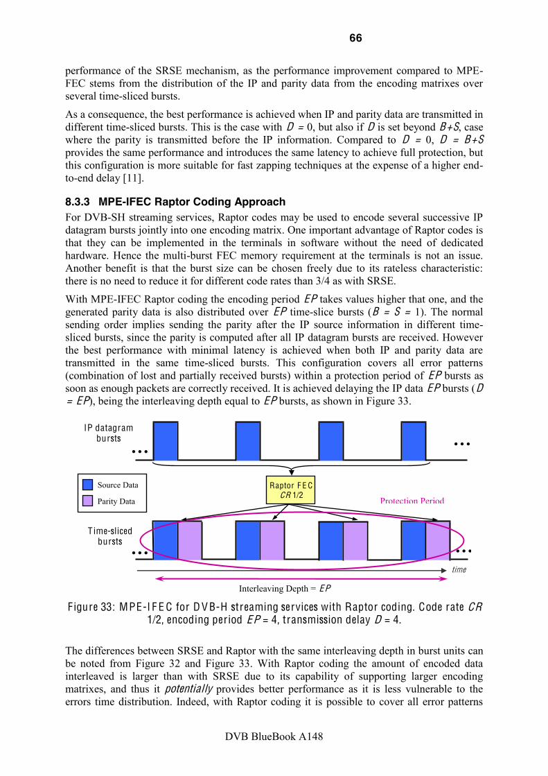
66
DVB BlueBook A148
performance of the SRSE mechanism, as the performance improvement compared to MPE-FEC stems from the distribution of the IP and parity data from the encoding matrixes over several time-sliced bursts.
As a consequence, the best performance is achieved when IP and parity data are transmitted in different time-sliced bursts. This is the case with D = 0, but also if D is set beyond B+S, case where the parity is transmitted before the IP information. Compared to D = 0, D = B+S provides the same performance and introduces the same latency to achieve full protection, but this configuration is more suitable for fast zapping techniques at the expense of a higher end-to-end delay [11].
8.3.3 MPE-IFEC Raptor Coding Approach For DVB-SH streaming services, Raptor codes may be used to encode several successive IP datagram bursts jointly into one encoding matrix. One important advantage of Raptor codes is that they can be implemented in the terminals in software without the need of dedicated hardware. Hence the multi-burst FEC memory requirement at the terminals is not an issue. Another benefit is that the burst size can be chosen freely due to its rateless characteristic: there is no need to reduce it for different code rates than 3/4 as with SRSE.
With MPE-IFEC Raptor coding the encoding period EP takes values higher that one, and the generated parity data is also distributed over EP time-slice bursts (B = S = 1). The normal sending order implies sending the parity after the IP source information in different time-sliced bursts, since the parity is computed after all IP datagram bursts are received. However the best performance with minimal latency is achieved when both IP and parity data are transmitted in the same time-sliced bursts. This configuration covers all error patterns (combination of lost and partially received bursts) within a protection period of EP bursts as soon as enough packets are correctly received. It is achieved delaying the IP data EP bursts (D = EP), being the interleaving depth equal to EP bursts, as shown in Figure 33.
IP datagram bursts
T ime-sliced bursts
time
Interleaving Depth = EP
Raptor F E C CR 1/2
Source Data
Parity Data Protection Period
F igure 33: MPE-I F E C for D V B-H streaming services with Raptor coding. Code rate CR
1/2, encoding period EP = 4, transmission delay D = 4.
The differences between SRSE and Raptor with the same interleaving depth in burst units can be noted from Figure 32 and Figure 33. With Raptor coding the amount of encoded data interleaved is larger than with SRSE due to its capability of supporting larger encoding matrixes, and thus it potentially provides better performance as it is less vulnerable to the errors time distribution. Indeed, with Raptor coding it is possible to cover all error patterns

67
DVB BlueBook A148
(combination of lost and partially received bursts) within a protection period as soon as enough packets are correctly received. Nevertheless, the actual gain in realistic field conditions is to be demonstrated.
Regarding fast zapping techniques, the configuration most suitable consists on transmitting the parity data before the IP information as with SRSE (this is the case with D = 2EP).
8.3.4 Fast Zapping Techniques The zapping time is defined as the time that a user has to wait to start watching the chosen TV channel since the instant of switching channels. For mobile TV, independently whether it is the first access to a service, or the recovery after a signal dropout, it is preferable that the user gets fast feedback about the suitability of the current location for reception. Subjective studies have shown that zapping times of less than 500 milliseconds are perceived as instantaneous, whereas more than two seconds are felt as annoying [FF08].
In DVB-H/SH, there is some inevitable delay due to its discontinuous transmission pattern, as users need to wait at least for the first burst of the new channel. The actual zapping time perceived by the users depends on the transmission errors suffered and the time of switching channels, being even possible to receive and display the channel of interest right away. For this reason it is very important to synchronize the multimedia stream with the time-slicing pattern, in such a way that terminals can start decoding the new channel immediately after the first burst has been received if successfully decoded. This can be achieved by including a random access point to the multimedia stream in each burst, and adjusting the buffer size of the codec to the amount of IP source data transmitted per burst. Note that terminals cannot display anything until receiving an Intra-coded frame (I-frame) of the new channel. Only I-frames contain all the information required to decode the complete frame. Most frames are differentially coded and depend on one or more previously transmitted frames (known as P or B frames). Hence, ideally for DVB-H/SH an integer number of group of pictures (GOP) should be transmitted per burst, as each GOP begins with an I-frame.
With intra-burst MPE-FEC the zapping time in covered areas is fundamentally limited by the time the user has to wait to receive the new burst, being in the worst case a full cycle time, as the processing time required for MPE-FEC decoding can be considered negligible (typical values for are about 0.1 s [11]. The cycle time between bursts, Tc, depends on the amount of IP source data transmitted in the burst Bs (note that it does not include the amount of parity information transmitted in the burst), and the data rate of the multimedia stream Rb, and it can be computed as:
cs
b
BTR
With multi-burst MPE-IFEC the zapping time is increased because terminals need to receive several time-sliced bursts with IP and parity data from the same encoding matrix in order to achieve full protection. In this case the zapping time is directly proportional to the interleaving depth and equals to the number of time-sliced bursts interleaved times the cycle time. However as the information arrangement is similar to the conventional approach with MPE-FEC, so that each burst contains source IP and FEC parity data, terminals in good reception conditions could be able to start reproducing the new TV channel right away as soon as they receive the first burst (if the burst contains a random access point to the multimedia stream as explained before), achieving the same zapping time conditions than with MPE-FEC.

68
DVB BlueBook A148
This alternative implies that users will experience an interruption of the service the first time an error is encountered, as terminals would need to buffer the remaining IP and parity data from the corresponding encoding matrix to achieve full MPE-IFEC protection. If the MPE-IFEC decoding process is successful, the stream will start from the point where it was interrupted. A solution to reduce the buffering time required to achieve full multi-burst FEC protection without reducing the interleaving depth is to delay the IP information at the transmitter such that the FEC parity data is sent ahead of the corresponding source IP data. This is achieved setting the delay parameter D = B+S for MPE-IFEC. This implies that the first bursts are not fully protected, as the parity is sent in previous bursts, but it allows a progressive reduction of the buffering time down to the number of bursts with IP data (i.e., B bursts for MPE-IFEC).
A solution to hide the buffering time from the perception of the users may be the use of adaptive media playout codecs [KSG04], able to slow down the multimedia stream playout such that the buffer needed for multi-burst FEC decoding can be built over time. Reference [KSG04] suggests that 20% of speed reduction is hardly perceivable by the user. Such techniques may require modification to existing video decoders, and especially audio decoders.
Both solutions have been extensively studied, specified and simulated in [33]. In the following we have excerpted 2 figures showing evolution of the video stream quality during the zapping transition, after the zapping instant, when MPE-IFEC buffers are being filled. Note that the image are being immediately displayed at zapping instant.
Figure 34: Evolution of quality over time for different values of alpha, D=0 and D = B+S = 10
The figure shows that the quality progressively increases with time, the time to reach this steady state being a function of the slow-down factor alpha; additionally these curves confirm the interest of using D=B+S, meaning sending FEC before the data in order to speed up protection. In addition, in the same reference, subjective tests have confirmed that a 20% of display speed reduction with appropriate tone adaptation is quite acceptable.
Fast zapping in DVB-H/SH is a very hot research topic nowadays, and a big research effort is currently being devoted to solve the transition between the fast zapping mode and the regular mode. For instance see [ASSLF10] where fast zapping options are discussed. The actual latency values that will be tolerated by the users implementing such fast zapping techniques are today an open issue and techniques able to conceal latencies are actively studied.

69
DVB BlueBook A148
8.4 Multi-Burst FEC Protection for DVB-H Streaming Services For DVB-H streaming services, the only upper layer FEC code currently standardized is MPE-FEC. As explained in Section 8.1, with MPE-FEC it is possible to recover from bursts partially received, but it cannot recover from complete lost bursts. However, lost bursts are common in the field due to the very rapid transition from near perfect reception to no reception at all characteristic of the underlying DVB-T standard, and have a major impact in the service coverage perceived by mobile users [HK07]. In order to recover from these errors, a FEC scheme spanning multiple bursts is required.
Multi-burst FEC has been already standardized above the IP layer in DVB-H for file delivery services using Raptor coding as application layer FEC [13] see Section 8.2. Although DVB-H is nowadays considered a mature technology, new multi-burst FEC schemes can be applied for streaming services to increase the robustness of the transmission [GB09]. This can be done either at the link layer with the compatible multi-burst FEC framework MPE-IFEC, or at the application layer with AL-FEC. Performance evaluation results of multi-burst FEC for DVB-H streaming services can be found in [GGBC08] for sliding Reed-Solomon encoding (SRSE) and in [GBGC09] for Raptor coding. Results are very promising, and show that it is possible to seriously decrease the number of transmission errors in real terrestrial networks.
The problem is that, in addition to the existing standard restriction to using different technique than MPE-FEC, existing DVB-H terminals do not count with the necessary hardware to handle the increased memory requirements. Different options are possible for implementing a multiple burst protection in the terminal where memory requirement is not an issue, in addition to the fast memory originally dedicated for MPE-FEC.
1) Perform a multi-burst protection with Raptor coding either at the link layer with MPE-iFEC or at the application layer. AL-FEC can be implemented following the FEC streaming framework defined by the IETF and already adopted by 3G MBMS [15]. Its introduction would require minor changes in the current IPDC specifications of the content delivery protocols. It should be pointed out that the performance of Raptor coding at the application layer would be practically the same as for MPE-IFEC, and that only some implementation and signaling specific aspects would differ.
2) Implement Reed-Solomon in software using recent findings in the binary image of RS code, see Section 6.3.1. Further investigations are needed to validate that the performance are similar to hardware decoding. Based on simulation results, MPE-IFEC encoding could possibly, in a second step, be optimized for this type of RS decoding.
As a consequence, multiple burst FEC protection providing significant performance gain can be introduced in the upper layer FEC as a software update, and still be backwards-compatible with existing DVB-H networks and terminals. They could rely on DVB-SH MPE-IFEC or MBMS CDP that would require minor if any modifications for such a purpose.
8.5 MPE-FEC/MPE-IFEC in DVB-H/SH for Layered Streaming Transmission
8.5.1 Overview Unlike a single layer video codec (e.g., H.264/AVC), a multi-layer codec like SVC differentiates in the importance of each of its sub-streams. The so-called base layer is the most important layer, as it is always required for decoding. When broadcasting multi-layered services as described in Section 2.3, it is in general beneficial to provide a differentiation in robustness for the different video layers. This concept is known as Unequal Error Protection (UEP), in opposition to Equal Error Protection (EEP) schemes that provide the same level of

70
DVB BlueBook A148
robustness to the different layers. UEP schemes allow, on the one hand, increasing the robustness of the more important layers and, on the other hand, providing the desired service behavior (e.g., coverage extension or graceful service degradation).
In DVB-H and DVB-SH, it is possible to provide a differentiation in robustness for a multi-layer video transmission such as SVC with MPE-FEC on a per service basis, such that more parity (repair) data is transmitted to compensate for potential transmission losses for the base layer than for the enhancement layers.
8.5.2 MPE-FEC for Layered Transmission in DVB-H/SH When combining a multi-layer video codec with MPE-FEC, the source IP information of each video sub-stream is encoded and transmitted in different time-sliced bursts. This way, the MPE-FEC code rate can be adjusted individually for each burst depending on the importance of each layer. Terminals correctly receiving all bursts would experience the full video quality. Approaches like coverage extension or graceful degradation require a suitable configuration of the MPE-FEC code rate over the different layers.
F igure 35: SV C transmission with two layers over D V B-H/SH with MPE-F E C using
different code rates.
Figure 35 shows an example of SVC delivery in DVB-H/SH with MPE-FEC. There are two quality layers (base layer and enhancement layer with e.g., spatial, temporal or SNR scalability), which are transmitted in two different time-sliced bursts, one immediately after the other to save power consumption in the terminals. The enhancement layer predicts from the base layer as denoted by the red arrows. As the enhancement layer has a lower importance than the base layer, it has a less robust MPE-FEC code rate (i.e., less repair data is transmitted).
8.5.3 MPE-IFEC for Layered Transmission in DVB-H/SH The MPE-IFEC extends the MPE-FEC scheme to an inter-burst protection. The sub-streams of a multi-layer codec can be mapped in a similar way as shown before for MPE-FEC on different time-sliced bursts. To avoid timing synchronization issues, the interleaving depth should be the same for the different layers, but
the MPE-IFEC code rate can be adjusted for the different layers following the different importance and desired service behavior. Figure 24 shows an example with two quality layers which are transmitted in different time-sliced bursts. One immediately after the other as in the MPE-FEC example shown in Figure 35, but in this case two bursts are jointly encoded with a
Time-sliced bursts
IP datagram bursts
RS F E C C R 1/2
RS F E C C R 3/4
RS F E C C R 1/2
RS F E C C R 3/4
Enhancement Layer
Base Layer
Source Data
Enhancement Layer
Base Layer
Parity Data
SVC Predictions
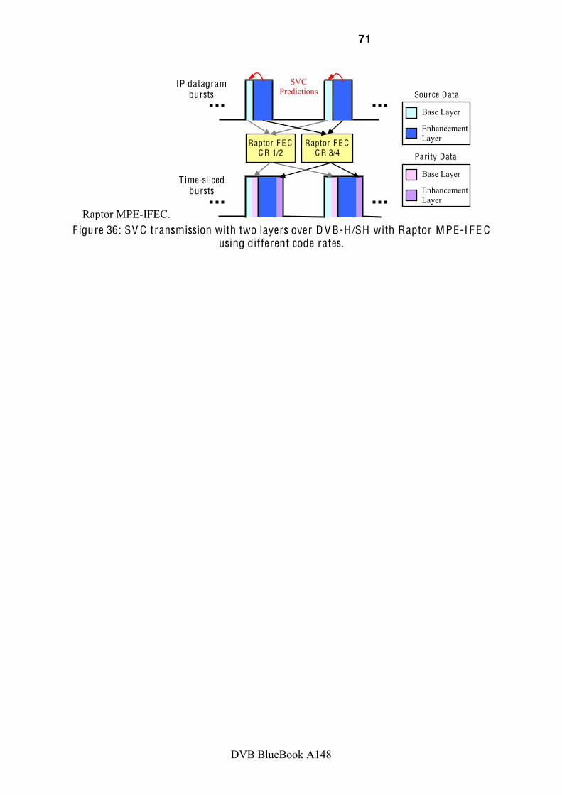
71
DVB BlueBook A148
Raptor MPE-IFEC. F igure 36: SV C transmission with two layers over D V B-H/SH with Raptor MPE-I F E C
using different code rates.
T ime-sliced bursts
IP datagram bursts
Raptor F E C C R 1/2
Raptor F E C C R 3/4
Enhancement Layer
Base Layer
Source Data
Enhancement Layer
Base Layer
Parity Data
SVC Predictions

72
DVB BlueBook A148
8.6 DVB-RCS+M for Mobile Satellite Data Services
8.6.1 Overview The second generation of the Digital Video Broadcasting standard for satellite transmission, DVB-S2 [7], is the most advanced satellite distribution technology that builds on the success of DVB-S. DVB-S2 has benefited from the latest progress in channel coding and modulation adaptation to achieve performance that approaches the theoretical Shannon limits. This adaptation requires a return channel, the Return Channel Satellite (RCS) standard to inform to the transmitter current channel conditions [6]. This feedback enables transmission at the most efficient coding and modulation scheme dependent upon channel conditions but also antenna
within the satellite coverage. Besides, the access layer attains a broader scope than in DVB-S by enabling unicast services.
These standards were defined for fixed terminals. However, increasing demand for broadband communications on mobile terminals, specifically collective mobile terminals, have resulted in the definition of a new extension of these standards, DVB-RCS+M [14]. The reason for the extension is that terminals installed in a mobile platform, such as train, ship, or aircraft, are exposed to challenging environments that will impact the system performance.
In DVB-RCS+M, advanced fade countermeasures for mobile use have been included on top of the DVB-S2 transmission in the form of upper layer FEC on for both, the forward downlink and the return uplink. The usage of upper layer FEC is especially powerful as it allows dynamic coding, which can be tuned in a closed-loop approach. Moreover, different QoS classes with different FEC redundancy profiles can be supported. These new features require cross-layer designs of the queuing architectures, two examples are given herein below.
8.6.2 FEC Architectures In order to define backwards compatible FEC signaling for unicast traffic, cross-layer architectures are needed. They should allow adaptive link layer FEC following physical layer dynamics while maintaining backwards compatible FEC signaling for unicast traffic. In the following, two examples are given [VVL08], [LSVV08].
8.6.2.1 L L-F E C per-Mobile T erminal The datacast (multicast/broadcast and unicast) transmission cross-layer architecture with either MPE-FEC over transport streams or GSE over Generic Streams (GS) is shown in Figure 37. This architecture aggregates traffic and creates an Elementary Stream (ES) per-mobile terminal. This means that a PID (Packet Identifier) is needed per mobile terminal. The packets are then aggregated according to the physical layer parameters (MODCOD). This architecture allows QoS scalability, i.e. it is possible to assign different FEC levels per QoS. This is possible by introducing parallel FEC processes each with different FEC protection levels. The drawback of this option is the scalability with the number of terminals since there is a limited number of PID and therefore a small address range could be provided. Furthermore, the level of traffic aggregation achieved when using one PID per terminal is low. This not only increases delay and jitter but also it may decrease FEC efficiency by having to use padding to fill up the FEC frame.
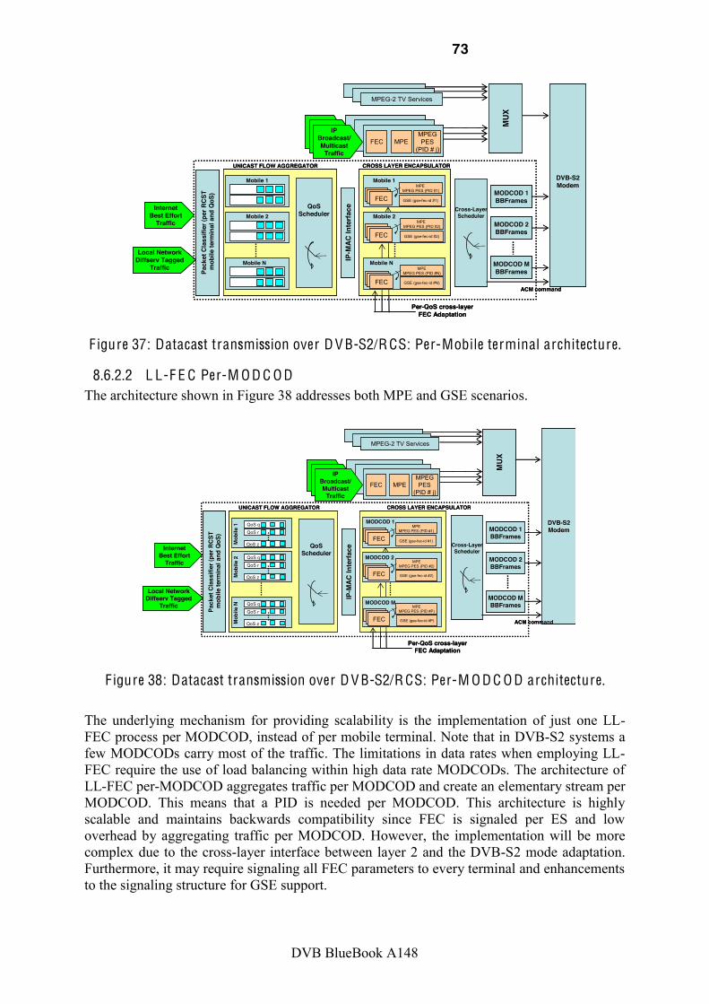
73
DVB BlueBook A148
IPBroadcast/Multicast
TrafficFEC MPE
MPEGPES
(PID # j)
MPEG-2 TV Services
MUX
InternetBest Effort
Traffic
Local NetworkDiffserv Tagged
Traffic Pack
etCl
assi
fier(
perR
CST
mob
ilete
rmin
al a
ndQ
oS)
Mobile 1
Mobile 2
Mobile N IP-M
AC In
terfa
ce
Mobile 1MPE
MPEG PES (PID #1)
Cross-LayerScheduler
MODCOD 1BBFrames
MODCOD 2BBFrames
MODCOD MBBFrames
DVB-S2Modem
UNICAST FLOW AGGREGATOR CROSS LAYER ENCAPSULATOR
ACM command
GSE (gse-fec-id #1)QoS
Scheduler
FEC
Per-QoS cross-layerFEC Adaptation
Mobile NMPE
MPEG PES (PID #N)
GSE (gse-fec-id #N)FEC
MPE MPEG PES (PID #2)
GSE (gse-fec-id #2)FEC
Mobile 2
!
F igure 37: Datacast transmission over D V B-S2/R CS: Per-Mobile terminal architecture.
8.6.2.2 L L-F E C Per-M O D C O D The architecture shown in Figure 38 addresses both MPE and GSE scenarios.
!
InternetBest Effort
Traffic
Local NetworkDiffserv Tagged
Traffic
Pack
etCl
assi
fier(
perR
CST
mob
ilete
rmin
al a
ndQ
oS)
Mob
ile1
QoSScheduler
IP-M
AC In
terfa
ce
MODCOD 1MPE
MPEG PES (PID #1)
GSE (gse-fec-id #1)
DVB-S2Modem
UNICAST FLOW AGGREGATOR CROSS LAYER ENCAPSULATOR
QoS q
QoS r
QoS z
Mob
ile2 QoS q
QoS r
QoS z
Mob
ileN QoS q
QoS r
QoS z
IPBroadcast/Multicast
TrafficFEC MPE
MPEGPES
(PID # j)
MPEG-2 TV Services
MUX
Cross-LayerScheduler
MODCOD 1BBFrames
MODCOD 2BBFrames
MODCOD MBBFrames
ACM command
FEC
MPEMPEG PES (PID #P)
GSE (gse-fec-id #P)
MODCOD M
FEC
MPEMPEG PES (PID #2)
GSE (gse-fec-id #2)
MODCOD 2
FEC
Per-QoS cross-layerFEC Adaptation
InternetBest Effort
Traffic
Local NetworkDiffserv Tagged
Traffic
Pack
etCl
assi
fier(
perR
CST
mob
ilete
rmin
al a
ndQ
oS)
Mob
ile1
QoSScheduler
IP-M
AC In
terfa
ce
MODCOD 1MPE
MPEG PES (PID #1)
GSE (gse-fec-id #1)
DVB-S2Modem
UNICAST FLOW AGGREGATOR CROSS LAYER ENCAPSULATOR
QoS q
QoS r
QoS z
Mob
ile2 QoS q
QoS r
QoS z
Mob
ileN QoS q
QoS r
QoS z
IPBroadcast/Multicast
TrafficFEC MPE
MPEGPES
(PID # j)
MPEG-2 TV Services
MUX
Cross-LayerScheduler
MODCOD 1BBFrames
MODCOD 2BBFrames
MODCOD MBBFrames
ACM command
FEC
MPEMPEG PES (PID #P)
GSE (gse-fec-id #P)
MODCOD M
FEC
MPEMPEG PES (PID #2)
GSE (gse-fec-id #2)
MODCOD 2
FEC
Per-QoS cross-layerFEC Adaptation !
F igure 38: Datacast transmission over D V B-S2/R CS: Per-M O D C O D architecture.
The underlying mechanism for providing scalability is the implementation of just one LL-FEC process per MODCOD, instead of per mobile terminal. Note that in DVB-S2 systems a few MODCODs carry most of the traffic. The limitations in data rates when employing LL-FEC require the use of load balancing within high data rate MODCODs. The architecture of LL-FEC per-MODCOD aggregates traffic per MODCOD and create an elementary stream per MODCOD. This means that a PID is needed per MODCOD. This architecture is highly scalable and maintains backwards compatibility since FEC is signaled per ES and low overhead by aggregating traffic per MODCOD. However, the implementation will be more complex due to the cross-layer interface between layer 2 and the DVB-S2 mode adaptation. Furthermore, it may require signaling all FEC parameters to every terminal and enhancements to the signaling structure for GSE support.

74
DVB BlueBook A148
9 Annex C Illustrative Performance Evaluation Examples for Upper Layer FEC
9.1 Synthesis The following simulations are provided:
Environment A V C SV C & E EP SV C & U EP SV C L A-F E C D V B-H + MPE-F E C (9.2.2) (9.2.1) (9.2.1) (9.2.2) D V B-H + MPE-I F E C (9.2.3 & 9.2.4) (9.2.3) (9.2.3 & 9.2.4) (9.2.4)
D V B-SH + MPE-I F E C (9.3) (9.3) (9.3) N/A Table 2: Simulated scenarios
The tables below present a specific synthesis of improvements provided by usage of application-aware techniques.
SV C + Standard F E C SV C + Layer-Aware F E C
Required bit rate Depends on the code-rate Depends on the code-rate
(same as with standard FEC)
Redundancy generation Each layer is protected independently
Cross layer error protection. Protection of more important layer increased without additional bit rate
Optimal code rate distr ibution
Unequal Error Protection (Service configuration might be challenging)
Equal Error Protection (Simple service configuration)
Used F E C algorithm Reed Solomon/Raptor Raptor (see Annex 10)
Optimal code rate distr ibution for a fixed service bit rate of 1421
kbps (cp. 9.2.1)
Base layer: 0.6670 Enhancement Layer: 0.8604 PSNR (C/N 16dB): 31.9 dB
Base layer: 0.7740 Enhancement Layer: 0.7740 PSNR (C/N 16dB): 33.6 dB
+1.7 dB Table 3: Comparison of standard F E C vs. Layer-Aware F E C for SV C layered media
transmission
Single Layer (V G A) SV C (Q V G A+V G A) + Layer-
Aware F E C
Selected results for MPE-I F E C (cp. 9.2.4)
AVC: PSNR (C/N 18dB, EP 4): 32.2dB ESR (C/N 18dB, EP 4): 22.78%
LA-FEC EEP: PSNR (C/N 18dB, EP 4): 32 dB ESR (C/N 18dB, EP 4): 19.6%
Table 4: Comparison of single layer (V G A) vs. SV C (Q V G A+ V G A) and Layer-Aware F E C

75
DVB BlueBook A148
9.2 SVC Layered Transmission in Terrestrial Context (DVB-H) The simulations in this section are based on a broadcast scenario where two device capabilities, namely QVGA and VGA, are supported by a single DVB-H service either by using simulcast transmission or SVC, see Figure 39. For increasing the robustness of the service, MPE-FEC and MPE-iFEC (Raptor approach, including its SVC layer-aware extension), are evaluated using different code rate distributions.
V G A device
VG
AQ
VG
A
Q V G A device
H.2
64/A
VC S
VC
D V B-H
F igure 39: Support of different device capabilities (Q V G A+ V G A) using SV C or
simulcast in a D V B-H broadcast system. The simulation scenario consists on a Typical Urban 6-taps (TU6) channel model with a constant Doppler (i.e. user velocity), but with the average Carrier-to-Noise Ratio (CNR) varying dynamically over time resembling correlated shadowing (slow fading). The TU6 channel models the time variant small-scale fluctuations of the received signal due to receiver mobility (i.e., fast fading). The DVB-H physical layer transmission mode considered is: FFT size 8K, OFDM symbol guard interval (GI) 1/4, modulation 16-QAM and code rate 1/2, which provides a channel capacity of around 10 Mbps. The shadowing is characterized by a standard deviation of 5.5 dB and a correlation distance of 20 m (the spatial correlation follows a first-order exponential model). The operating RF frequency assumed is 600 MHz, which yields a user velocity of 54 km/h for 30 Hz Doppler.
The video encoding was performed using the JSVM 9.1 version. A simple rate control was employed to achieve an approximately constant service rate. We used a restricted version of the scalable high profile, where CABAC and 8x8 transform feature had been switched off. The video was encoded in small chunks, where each chunk consists of a preceding IDR frame followed by two groups of picture of size 16 (GOP16). Each chunk was encoded multiple times with different quantization parameters (QP) values. Depending on the selected video rate, the chunk with QP value providing a certain bit rate was selected and the different chunks were concatenated to one video stream. The chunk wise encoding gives a random access point (RAP) interval of 1.1 seconds. seconds was selected for simulations. For SVC, we encoded two scalable layers. In particular, a base layer which provides QVGA at 15 frames per second (fps), and an enhancement layer increasing the quality up to VGA at 30 fps. For simulcast transmission, both qualities were encoded as a single layer stream. The QVGA stream is exactly the same in both settings. VGA quality in terms of PSNR (Peak Signal-to-Noise Ratio) is similar for both encodings. A summary of the encoding parameters for SVC and simulcast can be found in Table 5. With the selected encoding, the additional QVGA service comes with an overhead compared to single layer VGA of 10.2% using SVC, and 42.2% using simulcast.

76
DVB BlueBook A148
Table 5: Encoding parameters for single layer and SV C stream
Quality Bit rate PSNR V G A SV C H .264/A V C Base layer
QVGA 15fps 421 kbps 37.6 dB
29.1 dB (up scaled) SV C Enhancement layer
VGA 30fps 679 kbps 35.1 dB
H .264/A V C QVGA 15fps 421 kbps 37.6 dB
H .264/A V C VGA 30fps 998 kbps 34.9 dB
In the simulations, two performance measures were considered: the Peak Signal-to-Noise Ratio (PSNR), and the Erroneous Second Ratio (ESR). The PSNR measurement was used for evaluation of the overall video quality after transmission. In case of frame losses, freeze frame error concealment is used, where the last decoded picture is just copied. For SVC, in case only the enhancement layer gets lost, the up scaled QVGA layer was used for PSNR calculation. The ESR was used for the evaluation of the service robustness. The ESR denotes the percentage without video playout (service outages) which appears if any frame could not be decoded due to lost packets. For the SVC stream, it is assumed that an outage only appears in case frames of the base layer get lost. Therefore, the ESR measure only takes into account base layer losses.
The two quality layers are transmitted in two different time-sliced bursts, the second immediately following the other. For the simulations with intra-burst FEC, the source block size for FEC generation is aligned to the chunk size (i.e. each source block starts with an IDR RAP and incorporates both GOP16s of the chunk). Therefore, the tune-in delay (latency) is 1.1 s. Figure 40 illustrates such a scheduling, where the red arrows show the layer dependencies in the SVC case.
Baselayer Enh. layer ...Base
layer Enh. layer...
Dependency Dependency
FEC
FEC
FEC
FEC
t
Protection ProtectionTime-sliced bursts
Burst 1 Burst 2 Burst 3 Burst 4
F igure 40: D V B-H transmission of SV C base (Q V G A @15fps) and enhancement layer (V G A @30fps) in different time-sliced bursts with MPE-F E C , the second immediately
following the other .
For the simulations with inter-burst FEC (see sections 9.2.3 and 9.2.4), two bursts per video chunk have been used. This configuration allows a stronger protection because the source data per burst is reduced. The first burst covers the IDR random access point plus one GOP16, and the second burst covers the other GOP16. In this case, the latency introduced by the multi-burst encoding with MPE-IFEC is 0.55 s per burst.
The conducted simulations cover different FEC schemes for SVC transmission: MPE-FEC (Section 9.2.1), MPE-iFEC (Section 9.2.3), and LA-FEC (sections 9.2.2 and 9.2.4), and compare it with single layer and simulcast.

77
DVB BlueBook A148
9.2.1 SVC Layered Transmission in Terrestrial Context (DVB-H) using Intra-Burst FEC (MPE-FEC)
The results in this section show how the performance of a layered transmission can be increased by applying a differentiation in robustness to the different layers with MPE-FEC. To make a fair comparison for each service setting, the overall service bit rate (including source and parity data) was fixed to 1421 kbps. Equal (EEP) and unequal error protection (UEP) settings were investigated. In these simulations, the TU6 channel model does not consider slow fading.
Four different MPE-FEC schemes across the two SVC layers are considered. In particular, three unequal error protections settings (UEP1, UEP2, UEP3) are compared against the equal error protection (EEP) case. The code rates are chosen in such a way that the overall bit rate (including source IP and parity data) remains constant. The code rates (CR) for each layer in the different settings are shown in Table 6. Note that in the UEP schemes, the more important base layer has a stronger protection than the enhancement layer.
Table 6: MPE-F E C code rate distr ibution for the SV C layers. E EP U EP1 U EP2 U EP3
Q V G A @ 15fps 0.7740 0.7490 (3/4) 0.6670 (2/3) 0.6089 V G A @ 30fps 0.7740 0.7893 0.8604 0.9317
Figure 41 show the IP packet error rate (IP PER) for the base and enhancement layer for the different C/N values for 30 Hz Doppler frequency. As expected, when increasing the protection of the base layer the IP PER decreases, at the expense of a higher IP PER at the enhancement layer.
5 10 15 20 25
0
10
20
30
40
50
60
70
80
90
100
CNR (dB)
IP P
ER (%
)
Enhancement Layer
SVC MPE-FEC EEPSVC MPE-FEC UEP1SVC MPE-FEC UEP2SVC MPE-FEC UEP3
5 10 15 20 250
10
20
30
40
50
60
70
80
90
100
CNR (dB)
IP P
ER (%
)
Base Layer
SVC MPE-FEC EEPSVC MPE-FEC UEP1SVC MPE-FEC UEP2SVC MPE-FEC UEP3
F igure 41: IP packet er ror rate for the base and enhancement SV C layers for different
MPE-F E C settings. T U6 channel model. Doppler frequency 30 Hz. Figure 42 shows the erroneous seconds ratio (ESR) of the video stream for the different settings. Recall that the ESR measurement only takes losses in the SVC base layer into account.

78
DVB BlueBook A148
5 10 15 20 250
10
20
30
40
50
60
70
80
90
100
CNR (dB)
ESR
(%)
SVC MPE-FEC EEPSVC MPE-FEC UEP1SVC MPE-FEC UEP2SVC MPE-FEC UEP3
F igure 42: Average er roneous second ratio for different MPE-F E C settings.
T U channel model. Doppler frequency 30 Hz. As the ESR performance only depends on the protection of the base layer, the best performance is achieved by UEP3 setting, which has a very low protection in the enhancement layer but a strong protection in the base layer. However, in terms of overall PSNR quality, this is not the best setting, as shown in Figure 43. Therefore, both ESR and PSNR performance should be jointly analyzed.
5 10 15 20 255
10
15
20
25
30
35
40Average PSNR Doppler 30Hz
PSNR
(dB)
CNR (dB)
14 15 16 17 18 19 20 21
26
27
28
29
30
31
32
33
34
35
Average PSNR Doppler 30Hz
PSNR
(dB)
CNR (dB)
SVC MPE-FEC EEPSVC MPE-FEC UEP1SVC MPE-FEC UEP2SVC MPE-FEC UEP3
F igure 43: Average PSNR for different MPE-F E C settings.
T U6 channel model. Doppler frequency 30 Hz.
In the figure, the UEP1 and UEP2 settings show a better performance than the EEP case for the whole range of CNR considered. Regarding the UEP3 case, the one that protects most the base layer at the expense of a very weak protection of the enhancement layer, it provides the highest video quality for CNR values lower than 14 dB. At higher CNR, the error rate is lower and it is more efficient to reduce the protection of the base layer and increase the protection of the enhancement layer. Therefore, for a given CNR (and Doppler), there is an optimum trade-off between the protection of each layer. For the CNR value that provides a 5% burst error rate, 17 dB, the scheme that provides the highest PSNR quality is UEP2.
Taking also into account that in the simulated setting the reliability of the QVGA service is increased by UEP as well, it can be concluded that with a proper unequal error protection the reliability of a multi layer transmission system is improved compared to EEP.

79
DVB BlueBook A148
Following observations can be drawn:
UEP increases the overall quality of the SVC transmission for the QVGA (base layer) service and the VGA (enhancement layer) service compared to EEP.
UEP increases the service robustness in terms of ESR. Due to the trade-off between base and enhancement layer protection, finding an optimal code rate distribution for UEP may be challenging.
9.2.2 SVC Layered Transmission in Terrestrial Context (DVB-H) using Intra-Burst FEC and Layer-Aware FEC (LA-FEC)
The performance of an SVC layered transmission can be further improved using the Layer-Aware FEC approach described in Section 6.3.2. The simulation environment is the same than in the previous section. For SVC, the conventional MPE-FEC scheme of DVB-H is compared with a Layer-Aware MPE-IFEC scheme Raptor-based with an encoding period (EP) of 1 (i.e., intra-burst FEC). To model a practical Raptor decoding implementation, a reception overhead of 1% is considered. The simulated code rate distributions for each setting are shown in Table 7. The single layer (VGA) case is also included. All settings require an overall service bit rate of 1421 kbps. The single layer case allows a lower code rate compared to the SVC EEP case because of the SVC video coding overhead. Simulcast (QVGA+VGA) would only allow a minimum code rate of 0.9896 for the VGA stream, which does not give a sufficient protection.
Table 7: F E C code rate distr ibutions for a fixed service bit rate of 1421 kbps
H .264/A V C
Single Layer(V G A)
H .264/A V C SI M U L C AST
(Q V G A+V G A)
SV C MPE-F E C U EP2
SV C MPE-F E C E EP L A-F E C E EP
Q V G A @15fps - 1 0.6670 (2/3) 0.7740 V G A @30fps 0.6995 0.9896 0.8604 0.7740
Figure 44 shows the IP packet error rate for the single layer case and for the base and enhancement layer of the SVC settings as a function of the CNR at a Doppler frequency of 30 Hz. The AVC IP PER curve is the same in both base and enhancement layer plots.
5 10 15 20 250
10
20
30
40
50
60
70
80
90
100
CNR (dB)
IP P
ER (%
)
Enhancement Layer
AVCSVC MPE-FEC EEPSVC MPE-FEC UEP2SVC LA-FEC EEP
5 10 15 20 250
10
20
30
40
50
60
70
80
90
100
CNR (dB)
IP P
ER (%
)
Base Layer
AVCSVC MPE-FEC EEPSVC MPE-FEC UEP2SVC LA-FEC EEP
F igure 44: IP packet er ror rate for the base and enhancement SV C layers for different
intra-burst F E C settings. T U6 channel model. Doppler frequency 30 Hz. The gain of the layer-aware FEC approach can be observed looking at the MPE-FEC and LA-FEC EEP curves. With LA-FEC, the IP PER of the base layer is significantly decreased compared to the MPE-FEC EEP setting. It almost reaches the performance of MPE-FEC UEP2 and AVC single layer. In the enhancement layer, for LA-FEC a higher IP PER can be

80
DVB BlueBook A148
observed than for MPE-FEC EEP (but still lower than with the MPE-FEC UEP2 setting). However, a successfully received enhancement layer is useless without the base layer.
Figure 45 shows the video quality in terms of PSNR for a VGA receiver. The single layer curve shows the best performance because of the more robust protection. The LA-FEC EEP curve approaches the single layer AVC curve, and outperforms all MPE-FEC schemes.
5 10 15 20 255
10
15
20
25
30
35
40Average PSNR Doppler 30Hz
PSNR
(dB)
CNR (dB)
AVC SL (VGA)SVC MPE-FEC EEPSVC MPE-FEC UEP2SVC-LAFEC-EEP
14 15 16 17 18 19 20 2126
27
28
29
30
31
32
33
34
35
36Average PSNR Doppler 30Hz
PSNR
(dB)
CNR (dB)
AVC SL (VGA)SVC MPE-FEC EEPSVC MPE-FEC UEP2SVC-LAFEC-EEP
F igure 45: Average PSNR for different intra-burst F E C schemes. T U6 channel model.
Doppler frequency 30 Hz. Figure 46 shows the erroneous second ratio of the video stream for the different cases previously considered.
5 10 15 20 250
10
20
30
40
50
60
70
80
90
100
CNR (dB)
ESR
(%)
AVC SL (VGA)SVC MPE-FEC EEPSVC MPE-FEC UEP2SVC LA-FEC EEP
F igure 46: Average er roneous second ratio for different intra-burst F E C schemes.
T U6 channel model. Doppler frequency 30 Hz. The LA-FEC EEP setting shows a significantly lower ESR value than the MPE-FEC EEP setting. Again, it approaches the MPE-FEC UEP2 and single layer AVC case performance.
The following observations can be drawn:
The single layer (VGA) curve shows the best performance due to the stronger protection of the transmission, which is possible through the lower media bit rate compared to SVC. The drawback is that only a single VGA service is provided.
For SVC, LA-FEC scheme outperforms all MPE-FEC combinations since the repair packets of the enhancement VGA layer also protect the more important base QVGA layer. Therefore, unequal error protection is already included within the FEC coding structure. A promising code rate distribution for LA-FEC is the EEP case.
There is only a small reduction in performance (in terms of both PSNR and ESR) between the single layer (VGA) and the SVC LA-FEC scheme, while the latter one

81
DVB BlueBook A148
provides an additional QVGA service. Note that the SVC performance could be further improved compared to AVC by transmitting two services in parallel, which would increase the burst duration and therewith the interleaving depth.
9.2.3 SVC Layered Transmission in Terrestrial Context (DVB-H) using Inter-Burst FEC (MPE-iFEC)
The current DVB-H standard does only specify the use of an intra-burst FEC mechanism (MPE-FEC) at the link layer. However, it is possible to provide a multi-burst protection of the transmission for streaming services either at the link layer with MPE-IFEC (see Section 3.3) or at the application layer [GBGC09]. This section shows how the robustness of the DVB-H transmission can be increased with such inter-burst FEC schemes.
In these simulations, both fast fading and shadowing are considered. The overall service bit rate (including source and parity data) is fixed to 1682 kbps.
The frequency of the MPE-IFEC coding and decoding process expressed in burst units is usually refereed as encoding period. Here denoted as EP. In the simulations, the encoding period is varied through EP = (1, 2, 4, 9, and 18). An encoding period of 1 is similar to the intra-burst MPE-FEC case which introduces a latency of 0.55 seconds. An EP of 18 generates the parity data across 18 time-sliced bursts and introduces a latency of 9.9 seconds.
The single layer curve AVC-MPE-(i)FEC is included as a reference and its code rate was set to 0.6074. Due to the higher media bit rate, the simulcast (SIMUL) case only allows a code rate for each service of 0.8682 with the given service bit rate constraint of 1682 kbps. For SVC, we simulated several code rate distributions. Table 8 shows the selected code rate distribution for layered transmission using equal error protection (EEP) and unequal error protection (UEP).
Table 8: Selected code rate distr ibution across layers (Q V G A+V G A) at a fixed service bit rate of 1682 kbps.
A V C SL MPE-(i)F E C
A V C SI M U L MPE-(i)F E C
SV C MPE-(i)F E C E EP
SV C MPE-(i)F E C U EP1
Q V G A @ 15fps - 0.8682 0.6720 0.5400 V G A @ 30fps 0.6074 0.8682 0.6720 0.8000
The simulation results in terms of PSNR over CNR for EPs = (2, 4, 9, 18) are shown in four subplots summarized in Figure 47. Each subplot incorporates the EP=1 (EP1) as the MPE-FEC reference. In addition to the PSNR measurements, Figure 48 shows the erroneous second ratio (ESR) as a measure for the service robustness.
There are two plots in each subplot, where the plot on the left side shows an overview over the CNR range from 5 to 25. The red box marks the area, which is magnified in the subplot on the right size to show more details over the CNR range from 16 to 22 dB.

82
DVB BlueBook A148
5 10 15 20 255
10
15
20
25
30
35
40Average PSNR Doppler 10Hz
PSNR
[dB]
CNR [dB]
AVC SL MPE-FEC EP1AVC SIMUL MPE-FEC EP1SVC MPE-FEC EEPSVC MPE-FEC UEP1AVC SL MPE-IFEC EP2AVC SIMUL MPE-IFEC EP2SVC MPE-IFEC EEP EP2SVC MPE-IFEC UEP1 EP2
16 17 18 19 20 21 22
28
29
30
31
32
33
34
35Average PSNR Doppler 10Hz
PSNR
[dB]
CNR [dB]
5 10 15 20 2510
15
20
25
30
35
40Average PSNR Doppler 10Hz
PSNR
[dB]
CNR [dB]
AVC SL MPE-FEC EP1AVC SIMUL MPE-FEC EP1SVC MPE-FEC EEPSVC MPE-FEC UEP1AVC SL MPE-IFEC EP4AVC SIMUL MPE-IFEC EP4SVC MPE-IFEC EEP EP4SVC MPE-IFEC UEP1 EP4
16 17 18 19 20 21 22
28
29
30
31
32
33
34
35
Average PSNR Doppler 10Hz
PSNR
[dB]
CNR [dB]
5 10 15 20 2510
15
20
25
30
35
40Average PSNR Doppler 10Hz
PSNR
[dB]
CNR [dB]
AVC SL MPE-FEC EP1AVC SIMUL MPE-FEC EP1SVC MPE-FEC EEPSVC MPE-FEC UEP1AVC SL MPE-IFEC EP9AVC SIMUL MPE-IFEC EP9SVC MPE-IFEC EEP EP9SVC MPE-IFEC UEP1 EP9
16 17 18 19 20 21 22
28
29
30
31
32
33
34
35
Average PSNR Doppler 10Hz
PSNR
[dB]
CNR [dB]
5 10 15 20 2510
15
20
25
30
35
40Average PSNR Doppler 10Hz
PSNR
[dB]
CNR [dB]
AVC SL MPE-FEC EP1AVC SIMUL MPE-FEC EP1SVC MPE-FEC EEPSVC MPE-FEC UEP1 EP1SVC MPE-IFEC EEP EP18SVC MPE-IFEC UEP1 EP18
16 17 18 19 20 21 2228
29
30
31
32
33
34
35
Average PSNR Doppler 10Hz
PSNR
[dB]
CNR [dB]
F igure 47: Performance of different MPE-I F E C settings for encoding per iod EP1 (latency 0.55s), EP 2 (latency 1.1 s), EP4 (latency 2.2 s), EP9 (latency 4.95 s), and EP18 (latency 9.9 s) in terms of
PSNR .
For all cases (single layer AVC, and multi-layer SVC) cases, the performance in terms of PSNR improves with an increasing encoding period. For SVC, the UEP1 setting shows a

83
DVB BlueBook A148
stronger performance than the EEP setting for all CNR values below 15 dB for EP values of 1 and 2. For higher CNR values of 15 dB and larger EP values, EEP shows a similar performance than UEP1. With an increasing EP, errors get more and more evenly distributed across the layers. Therefore, at a certain CNR value, both layers can be corrected with EEP, but with UEP1, only the base layer can be corrected due to the lower protection in the enhancement layer.
However, due to the stronger base layer protection, the service outage probability is still lower with UEP, which is shown by the ESR measure in Figure 48.
5 10 15 20 250
10
20
30
40
50
60
70
80
90
100
CNR (dB)
ESR
(%)
AVC MPE-FEC EP1SVC MPE-FEC EEP EP1SVC MPE-FEC UEP1 EP1AVC MPE-FEC EP2SVC MPE-FEC EEP EP2SVC MPE-FEC UEP1 EP2
16 17 18 19 20 21 220
5
10
15
20
25
30
35
40
CNR (dB)
ESR
(%)
5 10 15 20 250
10
20
30
40
50
60
70
80
90
100
CNR (dB)
ESR
(%)
AVC SL MPE-FEC EP1SVC MPE-FEC EEP EP1SVC MPE-FEC UEP1 EP1AVC SL MPE-IFEC EP4SVC MPE-IFEC EEP EP4SVC MPE-IFEC UEP1 EP4
16 17 18 19 20 21 220
5
10
15
20
25
30
35
40
45
CNR (dB)
ESR
(%)

84
DVB BlueBook A148
5 10 15 20 250
10
20
30
40
50
60
70
80
90
100
CNR (dB)
ESR
(%)
AVC SL MPE-FEC EP1SVC MPE-FEC EEP EP1SVC MPE-FEC UEP1 EP1AVC SL MPE-IFEC EP9SVC MPE-IFEC EEP EP9SVC MPE-IFEC UEP1 EP9
16 17 18 19 20 21 22
0
5
10
15
20
25
30
35
40
45
CNR (dB)
ESR
(%)
5 10 15 20 250
10
20
30
40
50
60
70
80
90
100
CNR (dB)
ESR
(%)
AVC SL MPE-FEC EP1SVC MPE-FEC EEP EP1SVC MPE-FEC UEP1 EP1AVC SL MPE-IFEC EP18SVC MPE-IFEC EEP EP18SVC MPE-IFEC UEP1 EP18
16 17 18 19 20 21 22
0
5
10
15
20
25
30
35
40
CNR (dB)
ESR
(%)
F igure 48: Performance of different MPE-I F E C settings for encoding per iod EP1 (latency 0.55
s), EP2 (latency 1.1 s), EP4 (latency 2.2s), EP9 (latency 4.95 s), and EP18 (latency 9.9 s) in terms of er roneous second ratio (ESR).
The ESR value of the UEP1 SVC case is for all EP values lower than the single layer AVC case. It can be observed, that the gain of the multi-layer SVC cases is increasing with higher EPs. For EP values 9, 18, even the EEP setting shows a lower ESR value than the single layer curve. As expected in the discussion before, comparing the different multi-layer SVC cases, the best performance in terms of ESR is obtained with the configuration that protects more heavily the SVC base layer (i.e., UEP1 configuration).
The following observations can be drawn:
Inter-burst FEC enhances the transmission robustness of single layer (AVC) and multi-layer (SVC) transmission schemes without any increase in bit rate.
There is a trade-off between increased robustness and latency.
Multi-layer SVC services can provide an improved service robustness (in terms of ESR performance) compared to single layer AVC services, where parts of the media stream (i.e., SVC base layer) get a stronger protection (UEP).
For longer encoding periods, equal error protection performs similar than unequal error protection in terms of PSNR due to long time interleaving. But UEP shows stronger service robustness in terms of ESR.
9.2.4 Layered Transmission in Terrestrial Context (DVB-H) using Inter-Burst FEC (MPE-iFEC) and Layer-Aware FEC
The simulations in this section show how MPE-IFEC inter-burst FEC compares with the Layer-Aware Raptor based MPE-IFEC at different encoding periods. The simulation in this

85
DVB BlueBook A148
section are based on the same assumptions than in Section 9.2.3, which also incorporates the maximum allowed service bit rate of 1682 kbps (including source and parity data).
The simulations results for PSNR over CNR for EPs = (2, 4, 9, 18) are shown in four subplots summarized in Figure 55. Each subplot incorporates the intra-burst MPE-FEC reference case (EP1). In addition to the PSNR measurements, Figure 50 shows the erroneous second ratio as a measure for the service robustness.
5 10 15 20 2510
15
20
25
30
35
40Average PSNR Doppler 10Hz
PSNR
[dB]
CNR [dB]
AVC SL MPE-FEC EP1AVC SIMUL MPE-FEC EP1SVC MPE-FEC UEP1 EP1AVC SL MPE-IFEC EP2AVC SIMUL MPE-IFEC EP2SVC MPE-IFEC UEP1 EP2SVC LA-FEC EEP EP2SVC LA-FEC EEP EP1
16 17 18 19 20 21 2229
30
31
32
33
34
35Average PSNR Doppler 10Hz
PSNR
[dB]
CNR [dB]
5 10 15 20 2510
15
20
25
30
35
40Average PSNR Doppler 10Hz
PSNR
[dB]
CNR [dB]
AVC SL MPE-FEC EP1AVC SIMUL MPE-FEC EP1SVC MPE-FEC UEP1 EP1SVC LA-FEC EEP EP1AVC SL MPE-IFEC EP4AVC SIMUL MPE-IFEC EP4SVC MPE-IFEC UEP1 EP4SVC LA-FEC EEP EP4
16 17 18 19 20 21 22
29
30
31
32
33
34
35
Average PSNR Doppler 10Hz
PSNR
[dB]
CNR [dB]

86
DVB BlueBook A148
5 10 15 20 2510
15
20
25
30
35
40Average PSNR Doppler 10Hz
PSNR
[dB]
CNR [dB]
AVC SL MPE-FEC EP1AVC SIMUL MPE-FEC EP1SVC MPE-FEC UEP1 EP1SVC LA-FEC EEP EP1AVC SL MPE-IFEC EP9AVC SIMUL MPE-IFEC EP9SVC MPE-IFEC UEP1 EP9SVC LA-FEC EEP EP9
16 17 18 19 20 21 22
28
29
30
31
32
33
34
35
Average PSNR Doppler 10Hz
PSNR
[dB]
CNR [dB]
16 17 18 19 20 21 22
29
30
31
32
33
34
35
Average PSNR Doppler 10Hz
PSNR
[dB]
CNR [dB]
5 10 15 20 2510
15
20
25
30
35
40Average PSNR Doppler 10Hz
PSNR
[dB]
CNR [dB]
AVC SL MPE-FEC EP1AVC SIMUL MPE-FEC EP1SVC MPE-FEC UEP1 EP1SVC LA-FEC EEP EP1AVC SL MPE-IFEC EP18AVC SIMUL MPE-IFEC EP18SVC MPE-IFEC UEP1 EP18SVC LA-FEC EEP EP18
F igure 49: Performance of different MPE-I F E C settings for encoding per iod EP1 (latency 0.55s),
EP 2 (latency 1.1s), EP4 (latency 2.2s), EP9 (latency 4.95s), and EP18 (latency 9.9s) in terms of PSNR .
For all encoding periods EP1 to EP18 the Layer-Aware EEP approach shows a better performance as the SVC MPE-IFEC UEP1 setting. The combination of SVC and LA-FEC does even reach the performance of the single layer (SL) curve. Especially at low EP values, the gap between SL and LA-FEC is negligible, while SVC provides an additional QVGA service. The simulcast does not reach the performance of all other streams due to its weak protection. Figure 50 shows the erroneous second ratio (ESR) as a measure for the service robustness.

87
DVB BlueBook A148
5 10 15 20 250
10
20
30
40
50
60
70
80
90
100
CNR (dB)
ESR
(%)
AVC SL MPE-FEC EP1SVC MPE-FEC UEP1 EP1SVC LA-FEC EEP EP1AVC SL MPE-IFEC EP2SVC MPE-FEC UEP1 EP2SVC LA-FEC EEP EP2
16 17 18 19 20 21 220
5
10
15
20
25
30
35
40
CNR (dB)
ESR
(%)
5 10 15 20 250
10
20
30
40
50
60
70
80
90
100
CNR (dB)
ESR
(%)
AVC SL MPE-FEC EP1SVC MPE-FEC UEP1 EP1SVC LA-FEC EEP EP1AVC SL MPE-IFEC EP4SVC MPE-IFEC UEP1 EP4SVC LA-FEC EEP EP4
16 17 18 19 20 21 220
5
10
15
20
25
30
35
40
CNR (dB)
ESR
(%)
5 10 15 20 250
10
20
30
40
50
60
70
80
90
100
CNR (dB)
ESR
(%)
AVC MPE-FEC EP1SVC MPE-FEC UEP1 EP1SVC LA-FEC EEP EP1AVC MPE-IFEC EP2SVC MPE-IFEC UEP1 EP9SVC LA-FEC EEP EP9
16 17 18 19 20 21 220
5
10
15
20
25
30
35
40
CNR (dB)
ESR
(%)
5 10 15 20 250
20
40
60
80
100
CNR (dB)
ESR
(%)
AVC SL MPE-FEC EP1SVC MPE-FEC UEP1 EP1SVC LA-FEC EEP EP1AVC SL MPE-IFEC EP18SVC MPE-IFEC UEP1 EP18SVC LA-FEC EEP EP18
16 17 18 19 20 21 22
0
10
20
30
40
CNR (dB)
ESR
(%)
F igure 50: Performance of different MPE-I F E C settings for encoding per iod EP1 (latency 0.55
s), EP 2 (latency 1.1 s), EP4 (latency 2.2 s), EP9 (latency 4.95 s), and EP18 (latency 9.9s) in terms of er roneous second ratio (ESR).

88
DVB BlueBook A148
For short encoding periods (EP1-EP2), the ESR value of the LA-FEC EEP setting is similar to the MPE-IFEC UEP 1 setting. For longer EP values (EP4-EP18), the ESR difference between UEP 1 and LA-FEC EEP is increasing. However, using LA-FEC, the SVC multilayer transmission shows a lower ESR value than the single layer curve for all encoding periods, while reaching a similar PSNR performance.
Following observations can be drawn:
LA-FEC EEP shows a better performance with different encoding periods than standard FEC in terms of PSNR for all EPs. For larger EP values, the service robustness of an UEP setting is stronger.
The combination of SVC and LA-FEC shows a similar performance as the single layer (VGA) curve in terms of PSNR and even a stronger robustness in terms of ESR. That is, with LA-FEC the introduction of a QVGA service comes almost for free.
9.3 SVC Layered Transmission in Satellite Context (DVB-SH) In this section we want to check that the combined usage of SVC and UEP can indeed improve the current DVB-SH coverage in rural outdoor for satellite coverage according to 2.3.1.2 principle by reduction of the targeted minimal value of C/N (Carrier to Noise ratio), named C/N min required for having good quality of TV/video service reception for DVB-SH channels:
- The good quality of TV/video service reception is defined as the 1-ESR5 criteria of 90%, according to DVB-SH standard.
- As described in 2.3.1.2, the broadcast operator wants to extend the broadcast coverage on a specified area, without increasing transmission power and without impacting the number of broadcasted services (modulation and channel coding rate remain constant), and impacting the less service quality. The broadcast operator wants to offer access to a basic video quality on an extended coverage, keeping the nominal video quality over the nominal coverage, all others parameters (power, number of services) being equal.
- A nominal video service of bit rate Rs is split into 2 complementary H.264 SVC services: a base service SB of bit rate RsB and an SNR enhancement service SE of bit rate RsE that increases the decoded video quality when combined with service SB. SB is protected using a channel coding rate RcB while SE is protected using a channel coding rate RcE.
- Let being the with > 1. Base service radio coverage is extended if different code rates are used:
11 RcRcB with > 1 or different interleaving (B+S) depths are used. Due to the disadvantage of using longer interleaver on the base service, thus increasing the overall zapping time and memory usage, the first solution is favored, having different code rates for the base and enhanced layers while keeping the overall bit rate.
IFEC configuration is configured such that ESR5 quality exceeds 90%: QPSK 1/2 - C/N=11.9dB, IFEC : CR = 2/3 & B+S = 9 => 1- ESR5 = 92.8%.

89
DVB BlueBook A148
1-ESR5 of LMS SUB QPSK 1/2 vs iFEC CR_ota
0
0,2
0,4
0,6
0,8
1
1,2
4 5 6 7 8 9 10 11 12
C/N (dB)
1-ES
R5
0.2
0.3
0.4
0.5
0.6
0.7
0.8
0.9
!"#$$%
&'()*+,"-.*,('+*,/0+1 2345
6$%
47!8,9:;;90;<*=+ -9,6$%,9-(,!" >,?@A,9-(,',7B!,/0+10= ('=)*,C*+/**= D.E,'=.,##FG.E
F igure 51: 1-ESR5 (%) w.r .t Rc vs. SNR (dB) for B+S=9 Then extension factor is selected.
Loss in high quality coverage , Rs=705kbps, Rc=2/3
0,5
0,6
0,7
0,8
0,9
1
1,1
0 50000 100000 150000 200000 250000 300000 350000 400000 450000 500000
Rs_base
Rc_e
nhan
ceme
nt
alpha=1,5
alpha=1,2
E
5!"* >,$FG?
!HC>,#$
$,IC
JH
K
!"* >,$FD?
!HC>,?$
$,IC
JH
F igure 52: sizing U EP with I F E C
RsB and is fixed, RcB is computed and RcE is selected using the curves in Figure 52. Three configurations are tested :
A) Rsb = 100kbps, ext =1.5 RcB = 0.44, Rce = 0.72, RsE = 605kbps, Burst_period = repetition interval = 1s
B) Rsb = 200kbps, ext = 1.5 RcB = 0.44 & Rce = 0.82, RsE = 505kbps, Burst_period = repetition interval = 1s
C) Rsb = 200kbps, ext = 1.2 RcB = 0.55 & Rce = 0.72, RsE = 505kbps, Burst_period = repetition interval = 1s
In terms of video quality, the following results are given:

90
DVB BlueBook A148
YZ2[.CP
3\E[.CP
L7B!
0W2W2]6^[WE[YWYZ3U3\\]
0W2W2Y6^][EWYWYZ3U3\\Y
0W2W236Z]^ESYWYZ3U3\\3
0W2W2S6]]^E^YWYZ3U3\\S
0W2W2W6[ZESYWYZ3U3\\W.0MN:6
M&NE0+('+* OICJHP3('<*('+*!*H-;:+0-=Q'R*(
YZ2[.CP
3\E[.CP
L7B!
0W2W2]6^[WE[YWYZ3U3\\]
0W2W2Y6^][EWYWYZ3U3\\Y
0W2W236Z]^ESYWYZ3U3\\3
0W2W2S6]]^E^YWYZ3U3\\S
0W2W2W6[ZESYWYZ3U3\\W.0MN:6
M&NE0+('+* OICJHP3('<*('+*!*H-;:+0-=Q'R*(
F igure 53: L MS-SUB (Rs = 705kbps) ref A V C @ 38.1dB PSNR Rsb=100kbps
YZE[.CP
Y3E].CP
L7B!
0W2W2]6_3WE^YWYZ3U3\\]
0W2W2Y6^_[E]YWYZ3U3\\Y
0W2W236Z\SE3YWYZ3U3\\3
0W2W2S6]\_EZYWYZ3U3\\S
0W2W2W6S[^E\YWYZ3U3\\W.0MN:6
M&NE0+('+* OICJHP3('<*('+*!*H-;:+0-=Q'R*(
YZE[.CP
Y3E].CP
L7B!
0W2W2]6_3WE^YWYZ3U3\\]
0W2W2Y6^_[E]YWYZ3U3\\Y
0W2W236Z\SE3YWYZ3U3\\3
0W2W2S6]\_EZYWYZ3U3\\S
0W2W2W6S[^E\YWYZ3U3\\W.0MN:6
M&NE0+('+* OICJHP3('<*('+*!*H-;:+0-=Q'R*(
F igure 54: L MS-SUB (Rs = 705kbps) ref A V C @ 38.1dB PSNR Rsb=200kbps
We have only a light degradation of PSNR (less than 2.2 dB). Note: In example, 4 enhancement layers were encoded, which significantly reduces the
coding efficiency. These multiple layers are used for allowing a simple rate control in the video stream by means of dropping dynamically excessive layers. As it is well-known, the additional layers bring additional overhead and therefore PSNR degradation at equal bit rates. So why is this mechanism used ? This mechanism of multiple layers is used because there is no today in the SVC toolbox means for providing at the encoder side CBR rate control that are needed for DVB-SH dumps usage. Therefore, the encoding performance could be significantly improved with adapted CBR control mechanisms and less enhancement layers as shown in [SW07-01].
In terms of C/Nmin we get following results.

91
DVB BlueBook A148
LMS SUB QPSK, 3 services, Rs=705kbps, Rc=2/3, alpha=1.2 & 1.5
0
0,2
0,4
0,6
0,8
1
1,2
4 5 6 7 8 9 10 11 12
C/N (dB)
1-ES
R5
Ref AVC, Rc=0.66 Base ext 1.5, Rcb=0.44
Enh. w ith Rsb=200kbps, ext 1.5, Rce=0.82 Enh. w ith Rsb=100kbps, ext 1.5, Rce=0.72
Base ext 1.2, Rce=0.55 Enh. w ith Rsb=200kbps, ext 1.2, Rce=0.72
6$%
5@B,)'0=,-9,S.E,9-(,C'H*,H*(T0"*,/0+1 >,#F8,U,8,.E,/0+1>,#F? B-,7B!,J*=';0+R 9-(,*=1'="*<*=+ C'H*,/0+1 !HC >,#$$,ICJH,U, >,#F8,'=.,/0+1 !HC >,?$$,ICJH,U, >,#F?
6$%,0H=-+,(*'"1*.
F igure 55: curve of 1-ESR5 (%) vs. C/N (dB) for B+S = 9
Therefore for Rsb = 200kbps and equal to 1.2, using Rcb = 0.55, Rce = 0.72, we observe a gain of gain in LMS sub urban environment on base service, while having a base service at 200kbps of acceptable quality (above 30dB PSNR for Foreman) and almost no loss on enhancement coverage.

92
DVB BlueBook A148
10 Annex D - Possible Integration of the Layer-Aware Approach in the DVB toolbox
The Layer-Aware approach could be integrated into the MPE-iFEC specification [12] or in the CDP specification [19], in both cases as an extension of the Raptor code. Note that the Raptor code was originally specified in the DVB toolbox inside the IP Datacast CDP over DVB-H specification [13]. The Raptor specification was subsequently replaced in the CDP specification by direct reference to the IETF RFC 5053 [32].
10.1 Integration in the CDP toolbox This section presents the extensions required for an integration of the LA-FEC approach (see Section 6.3.2 and [HSW08]) into the existing specification of the Raptor code in the CDP. The description targets a potential Annex F of the CDP of IP Datacast over DVB-H [13]. Annex F (informative): Layer-Aware Raptor extension The Layer-Aware extension of the Raptor code increases the robustness of a layered media transmission (e.g. SVC, MVC, MPEG Surround) by cross layer FEC generation, following exiting dependencies within the media stream. This Annex specifies the required extensions, based on the Raptor code specification defined in RFC 5053[32]. F.1 Layer-Aware Raptor To apply the Layer-Aware approach to the Raptor code specified in Section 5.4 [32], the Precoding process in Section 5.4.2 [32] and LT-Encoding process in Section 5.4.3 [32] must be extended to all dependent layers. That is, the extensions does not affect the base layer symbol generation. The extension uses the algoriths for Intermediate Symbol Generation specified in Section 5.4.2 [32], LT Encoding specified in Section 5.4.3 [32] and the Generators specified in Section 5.4.4 [32] leaving theses specifications and the defined constraints of the algorithms untouched. F.1.1 Additional Definitions for Layer-Aware Raptor This section gives additional definitions for the Layer-Aware Raptor to the existing definitions in Section 5.4 [32]. SUM(Xi; ; cond) be the sum of a vector X from element i n with a condition cond. If the condition is not fulfilled, the result is 0. Let f denote the layer number in incremental order following the layer dependencies, where f =0 specifies the base layer having no dependencies, f =1 is the first enhancement layer which

93
DVB BlueBook A148
is only dependent on f =0, f =2 is the second enhancement layer dependent on layer f =0 and f =1 and so on. The systematic Raptor encoder is used to generate repair symbols from a source block that consists of K f source symbols of dependency layer f. Symbols are the fundamental data units of the encoding and decoding process. For each source block all symbols are the same size. The atomic operation performed on symbols (sub-symbols) for both encoding and decoding is the exclusive-or operation. Let C f [0],C f [1] f [K f-1] denote the K f source symbols of layer f Let C f[0],C f[1] f[Lf-1] denote Lf intermediate symbols of layer f Let LTEncLA[(K0,K1 f),[(C0[0] 0[L0-1]) (C f[0] f[Lf-1])], X] be the Layer-Aware LT Encoding process specified in 5.4.5.3 [32] for the Encoding Symbol ID (ESI) X.
1) The K f source symbols C f [0], C f [1] f [K f-1] of all layers f satisfy the K f constraints: C f [X] = LTEncLA[(K0,K1 f),[(C0[0], C1[0] 0[L0-1]) (C f[0] f[Lf-1])], X], for all X, 0 f. (Systematic constraint, specified in 5.4.2.4.1 [32])
2) The Lf intermediate symbols of all layers f satisfy the pre-coding relationships defined in clause 5.4.2.3 [32] (Precoding constraint, specified in Section 5.4.2.4.1 [32]).
F.1.2 Example method for calculation of intermediate symbols This clause describes the method for calculation of the Lf intermediate symbols C f[0], C f[1] f[L1-1] of layer f =1 satisfying the constraints in clause 5.4.5.1 [32]. The proposed extension is derived from the exemplary algorithm in Section 5.4.2.4.2 [32]. D f be the column vector of layer f consisting of S+ H (as defined in 5.4.2.3 [32]) zero symbols followed by the K f source symbols C f [0], C f [1] f[K f-1]. Figure 56 depicts the layer aware matrix Af=1 with f=1 enhancement layers (cf. Figure 4 in 5.4.2.4.2 [32]) with the submatrices A0, A1, A2, A3, A4:
- A0 be calculated as specified for a single matrix A in 5.4.2.4.2 [32] for layer f =0 - A1 be calculated as proposed for a single matrix A in 5.4.2.4.2 [32] for layer f =1 - A2 be the L0 × L1 zero matrix - A3 be the (S1+ H1) × L0 zero matrix - A4 be the K1 × L0 extension of the generator matrix of the encoding symbols
generated by the LT Encoder for layer f =0

94
DVB BlueBook A148
GLDPC IS ZSxH
GHalf IH
GLT (0,...,K0-1)
K0 S0 H0
S0
H0
K0
GLDPC IS ZSxH
GHalf IH
GLT (0,...,K1-1)
K1 S1 H1
S1
H1
K1
ZL0xL1
Z(S1+H1)xL0
A0
A1
A2
A3Af=1
GLT (K0,...,K0+K1-1)
A4
L1L0
L 1L 0
F igure 56: Layer-Aware Extension of the matrix A f=1 for layer f=1. Matrix A0 and A1 are generated as
specified in 5.4.2.4.2 [32] (see F igure 4 in 5.4.2.4.2 [32]) for layer f=0 and layer f=1. Matrix A2 and A3 be zero matrices. And matrix A4 be the layer aware matrix extension.
The sub-matrix A4 is a continuation from the GLT matrix of sub-matrix A0 (ESI number 0 to K0-1) starting from ESI number K0 to ESI number K0+K1-1. The intermediate symbols for all layers C = [C0, C1 C f] can then be calculated as follows: C = Af
-1 ! D Note: Since the generation of the extended matrix Af is based on exactly the same algorithms as used for the standard matrix generation specified in 5.4.2.4.2 [32], it provides exactly the same characteristics. The intermediate symbols (C0[0], C0 C0[L0- (C f[0], C f C f[Lf-1]) can be produced by applying the same Raptor decoding processes to the K source symbols (C0 C0 C0 K0- (C f C f C f K f-1]) as described in 5.4.2.4.2 [32]. F.1.3 Layer-Aware LT Encoding process The LT encoding for a Layer-Aware Code uses the algorithms as specified in 5.4.3 [32] and 5.4.4 [32]. For Layer-Aware Encoding, the LT encoding process for layer d is extended to all intermediate symbols of layers (C0[0], C0 C0[L0- (Cf[0], Cf Cf[Lf-1]). The repair symbol S of layer f with ESI X is generated according to the following algorithm LTEncLA, which uses the generator LTEnc and Trip as specified in 5.4.4.3 [32] and 5.4.4.4 [32].
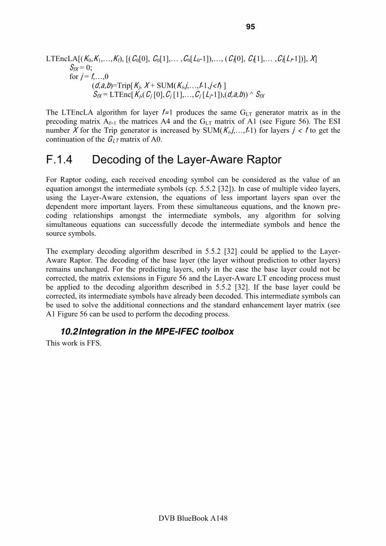
95
DVB BlueBook A148
LTEncLA[(K0,K1 Kf), [(C0[0], C0 C0[L0- (C f[0], C f C f[Lf-1])], X]
SfX = 0; for j = f
(d,a,b)=Trip[Kj, X + SUM(Ki,j f-1,j < f) ] SfX = LTEnc[Kj,(Cj [0],Cj Cj [Lj-1]),(d,a,b)) ^ SfX
The LTEncLA algorithm for layer f =1 produces the same GLT generator matrix as in the precoding matrix Af=1 the matrices A4 and the GLT matrix of A1 (see Figure 56). The ESI number X for the Trip generator is increased by SUM(Ki,j f-1) for layers j < f to get the continuation of the GLT matrix of A0.
F.1.4 Decoding of the Layer-Aware Raptor For Raptor coding, each received encoding symbol can be considered as the value of an equation amongst the intermediate symbols (cp. 5.5.2 [32]). In case of multiple video layers, using the Layer-Aware extension, the equations of less important layers span over the dependent more important layers. From these simultaneous equations, and the known pre-coding relationships amongst the intermediate symbols, any algorithm for solving simultaneous equations can successfully decode the intermediate symbols and hence the source symbols. The exemplary decoding algorithm described in 5.5.2 [32] could be applied to the Layer-Aware Raptor. The decoding of the base layer (the layer without prediction to other layers) remains unchanged. For the predicting layers, only in the case the base layer could not be corrected, the matrix extensions in Figure 56 and the Layer-Aware LT encoding process must be applied to the decoding algorithm described in 5.5.2 [32]. If the base layer could be corrected, its intermediate symbols have already been decoded. This intermediate symbols can be used to solve the additional connections and the standard enhancement layer matrix (see A1 Figure 56 can be used to perform the decoding process.
10.2 Integration in the MPE-IFEC toolbox This work is FFS.

96
DVB BlueBook A148
11 Bibliography [ASR09] -Solomon Codes on Graph for
DVB- Proc. Wireless World Research Forum, Paris, France, 2009.
[ASSLF10] ML. Alberi Morel, S. Kerboeuf, B. Sayadi, Y. Leprovost, F. Faucheux, Performance evaluation of channel change for DVB-SH streaming services
ICC2010, South Africa, 2020.
[BAQ01] D. Gozalves, , Dr David-Gomez Baquero, Link layer FEC protection of DVB-T2 services, iTEAM presentation Nov. 2009., TM-ULFEC0011
[BLM02] J. Byers, M. Luby, IEEE JSAC, vol. 20, no. 8, pp. 1528 40,
Oct. 2002.
[Cha72] IEEE Trans. Information Theory, vol. 18, pp. 170
182, Jan. 1972.
[CR08] LDPC-Proc. SPSC, Rhodes Island, Greece, 2008.
[EKME04] M. El-
Proc. Allerton, 2004.
[FF08] Proc. IEEE BMSB, Las Vegas, USA, 2008.
[FHST06] -H: Digital Proc. of the IEEE, vol. 94, no. 1, pp.
194-209, Jan. 2006.
[For96] IEEE Trans. Information Theory, vol. 12, pp. 125 131, Apr. 1996.
[FV04] -based Decoding of Reed-IEEE Communication Letters, vol.
7, pp. 452 454, July 2004.
[GB09] D. Gómez- Cost E fficient Provisioning of Mass Mobile Multimedia Services in Hybrid Cellular and Broadcasting SystemsUniversidad Politécnica de Valencia, Spain, 2009.
[GBB07] D. Gómez-Barquero and A. Bria, in DVB- Proc. IEEE VTC Spring, Dublin, Ireland, 2007.
[GBB09] D. Gómez-DVB- Wiley Wireless Communications and Mobile Computing, Computing, vol. 9, no. 6, pp. 733-744, June 2009.
[GBGC09] D. Gómez-for Mobile TV Delivery in IP Datacast over DVB- IEEE Trans. on Broadcasting, vol. 55, no. 2, pp. 396-406, June 2009.
97
DVB BlueBook A148
[GGBC08] D. Gozálvez, D. Gómez-of the MPE-IFEC Sliding RS Encoding for DVB- Proc. IEEE PIMRC, Cannes, France, 2008.
[HJ08] -H Field Trials: Studying Radio Channel Proc. IEEE BMSB, Orlando, USA, 2007.
[HL03] -Solomon IEEE Trans. Communications, vol. 51, pp.
1073 1081, July 2003.
[HMS+09] C. HHierarchical Modulation for DVB- Proc. IEEE BSMB, Bilbao, Spain, 2009.
[HSW08] Coding and Layer- Proc. IEEE ICME, Hannover, Germany, 2008.
[JN04] IEEE Communication Letters, vol. 8, pp. 244 246, Apr. 2004.
[JN06] J. Jiang and K. R. Narayan -Input-Soft-Output Decoding of Reed- IEEE Trans. Information Theory, vol. 52, no. 8, pp. 3746 3756, Aug. 2006.
[KSG04] Low-Delay Video Streaming Over Error- IEEE Trans. on Circuits and Systems, vol. 14, no. 6, pp. 841-851, June 2004.
[LC83] Error Control Coding: Fundamentals and Prentice Hall, 1983.
[Lub02] M. Luby Proc. IEEE F OCS, Vancouver, Canada, 2002.
[LSVV08] Link Layer FEC to DVB- Proc. SPSC, Rhodes Island, Greece, 2008.
[MU05] M. Mitzenmacher a Probability and Computing: Randomized Algorithms and Probabilistic Analysis
[O1] IEEE Transactions on Information Theory, vol. 47,
pp. 569 584, 2001. [O2] RFC5053, Raptor Forward Error Correction Scheme for Object Delivery,
October 2007. [PHK+07]
Performance Analysis of MPE-FEC Decoding Methods at the DVB-H Link IEEE Trans. on Broadcasting, vol. 53.
no. 1, pp. 263-275, March 2007.
[PV02] -Solomon IEEE Trans. Communications, vol. 50, pp. 1758 1768, Nov. 2002.
[Riz97] !"#$%&'()!"#$$&*+,-'+#*!.(/+(0, vol. 27, no. 2, April 1997.

98
DVB BlueBook A148
[SHM+07] H.264/AVC-based Scalable Video Coding (SVC) for Real Time Streaming in
Proc. IEEE ISCAS, New Orleans, USA, 2007.
[Sho06] IEEE Trans. on Information Theory, vol. 52, no. 6, pp. 2251-2567, June 2006.
[Sho08]
[SSW+08] T. Stockhammer, A. Shokrollahi, M. Watson, M. Luby and T. Gasiba,
Handbook of Mobile Broadcasting: DVB-H , DMB, ISDB-T and Media FLO, CRC Press, pp. 239-280, 2008.
[SW07] DVB, TM-
[SW07-01] DVB, TM- JVT-W071, Further Results for an RD-Optimized Multi-Loop SVC Encoder
[TLF+00] -2 and GMD IEEE Communication
Letters, vol. 5, pp. 209 211, May 2000.
[Ung03] of Reed- Proc. ISTC, Brest, France, 2003.
[VB91] -level Soft-decision Decoding of Reed-Solomon IEEE Trans. Communications, vol. 39, pp. 440 444, Mar. 1991.
[VVL08] F. Vieira, M. A. Vázquez Castro, and J. LArchitecture for DVB- Proc. SPSC, Rhodes Island, Greece, 2008.
[YCF02] Proc. Allerton, Monticello, USA,
2002.
[Yed04] -Solomon and Proc. ISIT, Chicago, USA, 2004.
END OF DOCUMENT