digital voltage indicators - hd electric … 100_500 series digital...4 description the digital...
TRANSCRIPT

Operating & Instruction Manual
DIGITAL VOLTAGEINDICATORSand ACCESSORIES
DVI-100
DVI-500
1475 Lakeside Drive • Waukegan, Illinois 60085 U.S.A. • 847.473.4980f a x 8 4 7 . 4 7 3 . 4 9 8 1 • w e b s i t e : w w w. H D E l e c t r i c C o m p a n y . c o m

2

3
Operating & Instruction Manual
DIGITAL VOLTAGEINDICATORSand ACCESSORIES
DESCRIPTION . . . . . . . . . . . . . . . . . . . . . . . . . . . . . . . . . . . . . . . . . . . . . . . . . . . . . . . . . . . . . . . . . . . . . . . . . . . . .4
IMPORTANT SAFETY INFORMATION . . . . . . . . . . . . . . . . . . . . . . . . . . . . . . . . . . . . . . . . . . . . . . . . . . . . . .5
HOW TO USE IT . . . . . . . . . . . . . . . . . . . . . . . . . . . . . . . . . . . . . . . . . . . . . . . . . . . . . . . . . . . . . . . . . . . . . . . . . . .6
ACCURACY . . . . . . . . . . . . . . . . . . . . . . . . . . . . . . . . . . . . . . . . . . . . . . . . . . . . . . . . . . . . . . . . . . . . . . . . . . . . .6-7
INDICATING VOLTAGE ON ELBOW TEST POINTS . . . . . . . . . . . . . . . . . . . . . . . . . . . . . . . . . . . . . . . . . .8
ACCESSORIES . . . . . . . . . . . . . . . . . . . . . . . . . . . . . . . . . . . . . . . . . . . . . . . . . . . . . . . . . . . . . . . . . . . . . . . . . .8-9
TECHNICAL SPECIFICATIONS . . . . . . . . . . . . . . . . . . . . . . . . . . . . . . . . . . . . . . . . . . . . . . . . . . . . . . . . . . . . .9
CARE AND MAINTENANCE . . . . . . . . . . . . . . . . . . . . . . . . . . . . . . . . . . . . . . . . . . . . . . . . . . . . . . . . . . . . . .10
WARRANTY AND LIABILITY . . . . . . . . . . . . . . . . . . . . . . . . . . . . . . . . . . . . . . . . . . . . . . . . . . . . . . . . . . . . . 12
1475 Lakeside Drive • Waukegan, Illinois 60085 U.S.A. • 847.473.4980f a x 8 4 7 . 4 7 3 . 4 9 8 1 • w e b s i t e : w w w. H D E l e c t r i c C o m p a n y . c o m
4
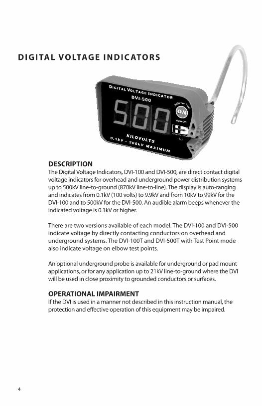
DESCRIPTIONThe Digital Voltage Indicators, DVI-100 and DVI-500, are direct contact digitalvoltage indicators for overhead and underground power distribution systemsup to 500kV line-to-ground (870kV line-to-line). The display is auto-rangingand indicates from 0.1kV (100 volts) to 9.9kV and from 10kV to 99kV for theDVI-100 and to 500kV for the DVI-500. An audible alarm beeps whenever theindicated voltage is 0.1kV or higher.
There are two versions available of each model. The DVI-100 and DVI-500indicate voltage by directly contacting conductors on overhead andunderground systems. The DVI-100T and DVI-500T with Test Point modealso indicate voltage on elbow test points.
An optional underground probe is available for underground or pad mountapplications, or for any application up to 21kV line-to-ground where the DVIwill be used in close proximity to grounded conductors or surfaces.
OPERATIONAL IMPAIRMENTIf the DVI is used in a manner not described in this instruction manual, theprotection and effective operation of this equipment may be impaired.
DIGITAL VOLTAGE INDICATORS

5
IMPORTANT SAFETY INFORMATION• Only trained, professional operating personnel should
use the DVI. The voltages this instrument operates at aredangerous and lethal. Severe injury or death can occurif improperly used.
• Risk of electrocution is inherent in or around high voltage.• Always use proper high voltage procedures, including
personal protective equipment, when working near oraround high voltage equipment or conductors.
• Do not exceed the DVI maximum voltage rating.• Assemble the DVI with the proper contact probe
for your application.• The DVI must be used with a hotstick of the
appropriate length for the voltage being measuredper your company and OSHA published requirements.
• Do not touch the DVI during measurements. The DVIhousing should be considered to be at the samevoltage as the conductor under test.
• Prior to using, inspect the instrument for any physicaldamage, cleanliness and check for proper working orderby pressing and holding the ON button. Do not proceedif the display does not indicate all 8’s or if the beeperdoes not sound.
• Never allow another high voltage or groundedconductor to contact the instrument during use. Keepthe DVI housing free and clear of all structures at all times.Bridging the DVI probe or housing from line-to-groundor line-to-line may cause a fault and arc.
• The DVI does not indicate voltages below 100 volts.Always use proper grounding procedures. A zerovoltage reading on the DVI does not mean the lineis dead or grounded.
• Grounded equipment or lines can appear to be livewhen in close proximity to energized conductors ifnot fully or properly grounded.
• Always test the DVI on a known voltage source before andafter each use, or use the PT-DVI Proof Tester® Voltage Indicator Tester.
• The DVI is a voltage indicator, not a voltmeter.Do not attempt to make accuratevoltage measurements for phasing or other applications with the DVI.
• The DVI is a direct contact device. The metal portion of the DVI probe must contact themetal conductor to be tested. Voltage indication on insulated conductors such as treewire or spacer wire will be much lower than actual and may not indicate any voltage at all.
• DVI voltage readings are sensitive to geometry. Read and understand the Accuracysection of this manual before using the DVI.
• The DVI indicates AC voltage only. It does not detect DC voltage such as chargedcapacitors or cable.
DVI-500T
DVI-500
DVI-100T
DVI-100
These important labels areaffixed to the products.Read and understandbefore proceeding.
6
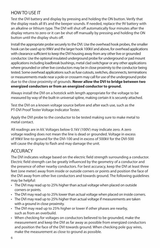
HOW TO USE ITTest the DVI battery and display by pressing and holding the ON button. Verify thatthe display reads all 8’s and the beeper sounds. If needed, replace the 9V battery withan alkaline or lithium type. The DVI will shut off automatically four minutes after thedisplay returns to zero or it can be shut off manually by pressing and holding the ONbutton until the display shuts off.
Install the appropriate probe securely to the DVI. Use the overhead hook probes, the smallerhook can be used up to 99kV and the larger hook 100kV and above, for overhead applicationswith clearance sufficient to keep the DVI housing away from any other live or groundedconductor. Use the optional insulated underground probe for underground or pad mountapplications including loadbreak bushings, metal clad switchgear or any other applicationswhere grounded or other live conductors may be in close proximity to the conductor beingtested. Some overhead applications such as fuse cutouts, switches, disconnects, terminationsor measurements made near a pole or crossarm may call for use of the underground probedue to the close proximity of grounds. Never allow the DVI to bridge between twoenergized conductors or from an energized conductor to ground.
Always install the DVI on a hotstick with length appropriate for the voltage to bemeasured by way of the built-in universal spline, making certain it is securely attached.
Test the DVI on a known voltage source before and after each use, such as thePT-DVI Proof Tester Voltage Indicator Tester.
Apply the DVI probe to the conductor to be tested making sure to make metal tometal contact.
All readings are in kV. Voltages below 0.1kV (100V) may indicate zero. A zerovoltage reading does not mean the line is dead or grounded. Voltage in excessof 99kV line-to-ground for the DVI-100 and in excess of 500kV for the DVI-500will cause the display to flash and may damage the unit.
ACCURACYThe DVI indicates voltage based on the electric field strength surrounding a conductor.Electric field strength can be greatly influenced by the geometry of a conductor andthe presence of other nearby conductors. For best accuracy, keep the DVI at least threefeet (one meter) away from inside or outside corners or points and position the face ofthe DVI away from other live conductors and towards ground. The following guidelinesmay be helpful:• The DVI may read up to 25% higher than actual voltage when placed on outside
corners or points.• The DVI may read up to 25% lower than actual voltage when placed on inside corners.• The DVI may read up to 25% higher than actual voltage if measurements are taken
with a ground in close proximity.• The DVI may read up to 25% higher or lower if other phases are nearby,
such as from an overbuild.• When checking for voltages on conductors believed to be grounded, make the
measurement and keep the DVI as far away as possible from energized conductorsand position the face of the DVI towards ground. When checking pole guy wires,make the measurement as close to ground as possible.
7
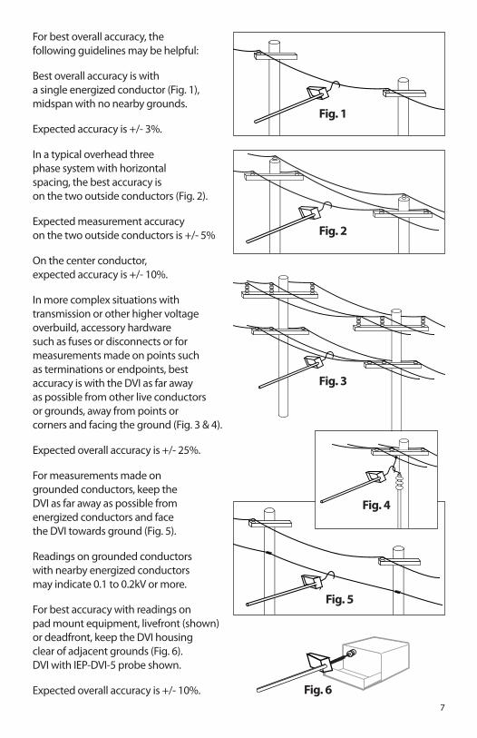
For best overall accuracy, thefollowing guidelines may be helpful:
Best overall accuracy is witha single energized conductor (Fig. 1),midspan with no nearby grounds.
Expected accuracy is +/- 3%.
In a typical overhead threephase system with horizontalspacing, the best accuracy ison the two outside conductors (Fig. 2).
Expected measurement accuracyon the two outside conductors is +/- 5%
On the center conductor,expected accuracy is +/- 10%.
In more complex situations withtransmission or other higher voltageoverbuild, accessory hardwaresuch as fuses or disconnects or formeasurements made on points suchas terminations or endpoints, bestaccuracy is with the DVI as far awayas possible from other live conductorsor grounds, away from points orcorners and facing the ground (Fig. 3 & 4).
Expected overall accuracy is +/- 25%.
For measurements made ongrounded conductors, keep theDVI as far away as possible fromenergized conductors and facethe DVI towards ground (Fig. 5).
Readings on grounded conductorswith nearby energized conductorsmay indicate 0.1 to 0.2kV or more.
For best accuracy with readings onpad mount equipment, livefront (shown)or deadfront, keep the DVI housingclear of adjacent grounds (Fig. 6).DVI with IEP-DVI-5 probe shown.
Expected overall accuracy is +/- 10%.
Fig. 1
Fig. 2
Fig. 3
Fig. 4
Fig. 5
Fig. 6
8
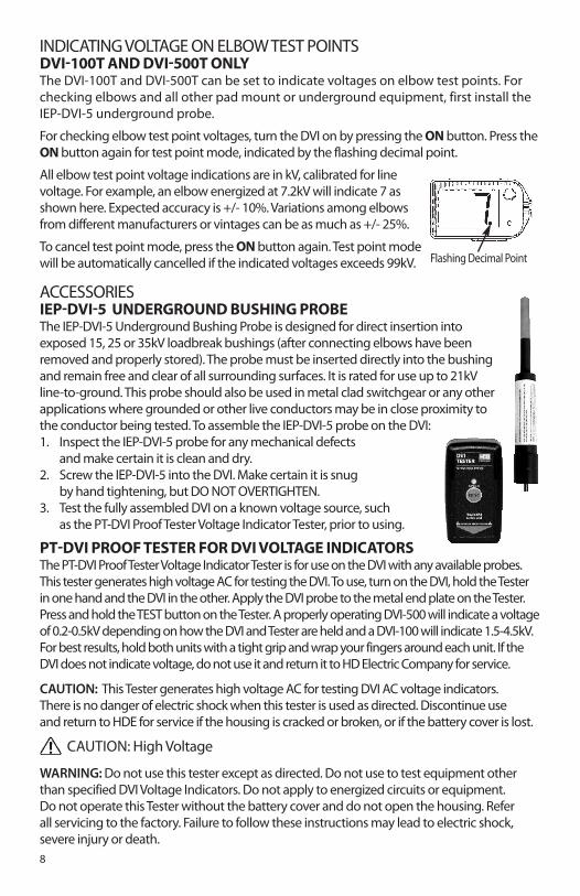
INDICATING VOLTAGE ON ELBOW TEST POINTS DVI-100T AND DVI-500T ONLYThe DVI-100T and DVI-500T can be set to indicate voltages on elbow test points. Forchecking elbows and all other pad mount or underground equipment, first install theIEP-DVI-5 underground probe.
For checking elbow test point voltages, turn the DVI on by pressing the ONbutton. Press theONbutton again for test point mode, indicated by the flashing decimal point.
All elbow test point voltage indications are in kV, calibrated for linevoltage. For example, an elbow energized at 7.2kV will indicate 7 asshown here. Expected accuracy is +/- 10%. Variations among elbowsfrom different manufacturers or vintages can be as much as +/- 25%.
To cancel test point mode, press the ONbutton again. Test point modewill be automatically cancelled if the indicated voltages exceeds 99kV.
ACCESSORIESIEP-DVI-5 UNDERGROUND BUSHING PROBEThe IEP-DVI-5 Underground Bushing Probe is designed for direct insertion intoexposed 15, 25 or 35kV loadbreak bushings (after connecting elbows have beenremoved and properly stored). The probe must be inserted directly into the bushingand remain free and clear of all surrounding surfaces. It is rated for use up to 21kVline-to-ground. This probe should also be used in metal clad switchgear or any otherapplications where grounded or other live conductors may be in close proximity tothe conductor being tested. To assemble the IEP-DVI-5 probe on the DVI:1. Inspect the IEP-DVI-5 probe for any mechanical defects
and make certain it is clean and dry.2. Screw the IEP-DVI-5 into the DVI. Make certain it is snug
by hand tightening, but DO NOT OVERTIGHTEN.3. Test the fully assembled DVI on a known voltage source, such
as the PT-DVI Proof Tester Voltage Indicator Tester, prior to using.
PT-DVI PROOF TESTER FOR DVI VOLTAGE INDICATORSThe PT-DVI Proof Tester Voltage Indicator Tester is for use on the DVI with any available probes.This tester generates high voltage AC for testing the DVI. To use, turn on the DVI, hold the Testerin one hand and the DVI in the other. Apply the DVI probe to the metal end plate on the Tester.Press and hold the TEST button on the Tester. A properly operating DVI-500 will indicate a voltageof 0.2-0.5kV depending on how the DVI and Tester are held and a DVI-100 will indicate 1.5-4.5kV.For best results, hold both units with a tight grip and wrap your fingers around each unit. If theDVI does not indicate voltage, do not use it and return it to HD Electric Company for service.
CAUTION: This Tester generates high voltage AC for testing DVI AC voltage indicators.There is no danger of electric shock when this tester is used as directed. Discontinue useand return to HDE for service if the housing is cracked or broken, or if the battery cover is lost.
CAUTION: High Voltage
WARNING: Do not use this tester except as directed. Do not use to test equipment otherthan specified DVI Voltage Indicators. Do not apply to energized circuits or equipment.Do not operate this Tester without the battery cover and do not open the housing. Referall servicing to the factory. Failure to follow these instructions may lead to electric shock,severe injury or death.
Flashing Decimal Point
9
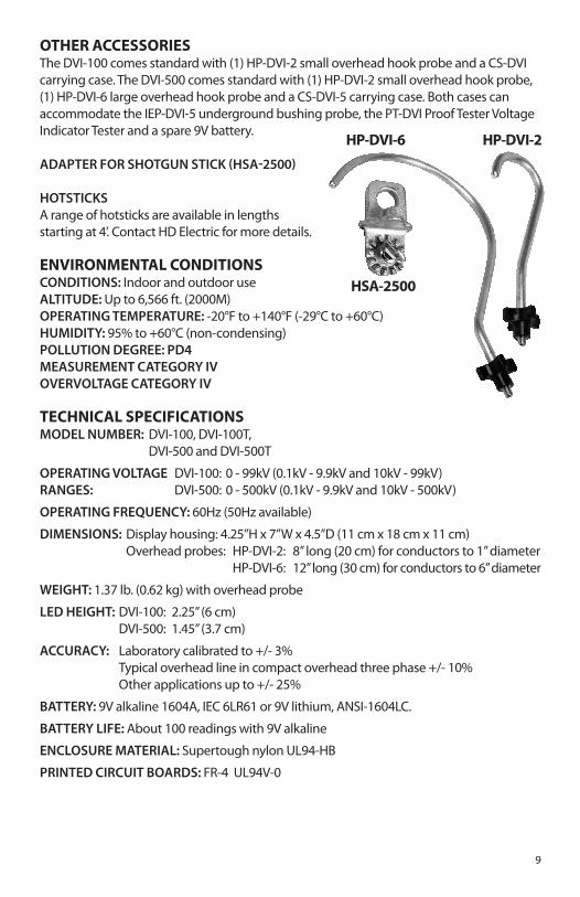
OTHER ACCESSORIESThe DVI-100 comes standard with (1) HP-DVI-2 small overhead hook probe and a CS-DVIcarrying case. The DVI-500 comes standard with (1) HP-DVI-2 small overhead hook probe,(1) HP-DVI-6 large overhead hook probe and a CS-DVI-5 carrying case. Both cases canaccommodate the IEP-DVI-5 underground bushing probe, the PT-DVI Proof Tester VoltageIndicator Tester and a spare 9V battery.
ADAPTER FOR SHOTGUN STICK (HSA-2500)
HOTSTICKSA range of hotsticks are available in lengthsstarting at 4’. Contact HD Electric for more details.
ENVIRONMENTAL CONDITIONSCONDITIONS: Indoor and outdoor useALTITUDE: Up to 6,566 ft. (2000M)OPERATING TEMPERATURE: -20°F to +140°F (-29°C to +60°C)HUMIDITY: 95% to +60°C (non-condensing)POLLUTION DEGREE: PD4MEASUREMENT CATEGORY IVOVERVOLTAGE CATEGORY IV
TECHNICAL SPECIFICATIONSMODEL NUMBER: DVI-100, DVI-100T,
DVI-500 and DVI-500T
OPERATING VOLTAGE DVI-100: 0 - 99kV (0.1kV - 9.9kV and 10kV - 99kV)RANGES: DVI-500: 0 - 500kV (0.1kV - 9.9kV and 10kV - 500kV)
OPERATING FREQUENCY: 60Hz (50Hz available)
DIMENSIONS: Display housing: 4.25”H x 7”W x 4.5”D (11 cm x 18 cm x 11 cm)Overhead probes: HP-DVI-2: 8” long (20 cm) for conductors to 1” diameter
HP-DVI-6: 12” long (30 cm) for conductors to 6” diameter
WEIGHT: 1.37 lb. (0.62 kg) with overhead probe
LED HEIGHT: DVI-100: 2.25” (6 cm)DVI-500: 1.45” (3.7 cm)
ACCURACY: Laboratory calibrated to +/- 3%Typical overhead line in compact overhead three phase +/- 10%Other applications up to +/- 25%
BATTERY: 9V alkaline 1604A, IEC 6LR61 or 9V lithium, ANSI-1604LC.
BATTERY LIFE: About 100 readings with 9V alkaline
ENCLOSURE MATERIAL: Supertough nylon UL94-HB
PRINTED CIRCUIT BOARDS: FR-4 UL94V-0
HP-DVI-2HP-DVI-6
HSA-2500

10
BATTERY REPLACEMENT INSTRUCTIONSTo replace the battery, open and remove the compartment on the bottom of the DVIhousing. Remove and dispose of the old battery, replacing it with a fresh, new 9-voltlithium or alkaline battery. Note battery polarity on the battery compartment. This com-partment cannot be reinserted if the battery polarity is reversed.
CARE AND MAINTENANCESTORAGE - It is recommended for protection of the DVI that it and its accessories
are stored in the carrying case provided.
CLEANLINESS - The molded housing is very rugged, but it should be kept clean andfree of dirt, grease and any other foreign materials. If the housing surfaceintegrity has been compromised in any way, remove from service andreturn to factory for repair or replacement.
CLEANING INSTRUCTIONS - To clean the DVI wipe with a damp cloth with water.Do not use harsh chemicals or solvents.
DAMAGE - If you suspect any mechanical or electrical damage, do not use the DVIand arrange for repair by returning to the factory.
CALIBRATION & TESTING - Regular calibration of the DVI is not required.There is no accessible calibration adjustment.
SERVICE - Return to HD Electric Company for service.
MANUFACTURING LOCATIONHD Electric Company • Waukegan, IL. 60085, USA

11
LIMITED WARRANTY AND LIMITATION OF LIABILITYThis warranty applies to all products sold by HD Electric Company (the "Products"); provided, however, that the term Products does not include anythird party products purchased through HD Electric Company, for which no warranties are made (the "Third Party Products"). Third Party Productsmay be subject to a separate manufacturer's warranty; [should you have any question regarding whether a separate warranty applies, please contactHD Electric Company].
NOTICE: READ THIS LIMITATION OF WARRANTY AND LIABILITY BEFORE BUYING OR USING THE PRODUCTS CONTAINED HEREIN.
It is impossible to eliminate all risks associated with the use of the Products. Risks of serious injury or death, including risks associated with electrocution,arcing and thermal burns, are inherent in work in and around energized electrical systems. Such risks arise from the wide variety of electrical systemsand equipment to which Products may be applied, the manner of use or application, weather and environmental conditions or other unknown factors,all of which are beyond the control of HD Electric Company.
HD Electric Company does not agree to be an insurer of these risks, and shall have no liability for any claims arising from such risks.
WHEN YOU BUY OR USE THESE PRODUCTS, YOU AGREE TO ACCEPT THESE RISKS.
HD Electric Company warrants to the original purchaser that the Products (excluding any third party products purchased through HD Electric Company,for which no warranties are made) will be free from defects in material and workmanship, under normal use and regular service, and preventativemaintenance for a period of one (1) year (ten (10) years for HDE Capacitor Controls) from the date of shipment (the “Warranty Period”). Should any failureto conform with this warranty be found during the Warranty Period, you must notify HD Electric Company of your claim within thirty (30) days of discovery,and within the Warranty Period. Your failure to give notice of claims of breach of warranty within the Warranty Period shall be deemed an absolute andunconditional waiver of claims for such defects. HD Electric Company will have no responsibility to honor claims received after the date the applicableWarranty Period expires.
Upon notice of your claim, HD Electric Company will provide a return authorization number, and further instructions on how to return the product forservice. You must follow HD Electric Company’s instruction. You are responsible for all Product removal, handling, re-installation, and shipping (bothto and from HD Electric Company). Products returned for repair, as well as repaired or replacement Products shall be sent postage / freight prepaid. Afterreceipt of a product which HD Electric Company determines is defective, HD Electric will, at its option, either (1) repair (or authorize the repair of) theProduct or (2) replace the Product, subject to the following: The Products are made using parts sourced from a variety of manufacturers. Due to the rapidlychanging technology environment, parts may become obsolete / unavailable over time (end of life). In the event that a Product cannot be repaired orreplaced due to unavailability of parts, HD Electric Company will use commercially reasonable efforts to obtain substitute parts or conduct work arounddesign, but cannot guarantee its ability to do so.
Items not found defective will be returned at your expense, or failing receipt of instruction from you on return of such items within five (5) business daysof our notice to you that the product is not defective, HD Electric may dispose of the product at its discretion and with no liability to you. HD ElectricCompany’s determination of defects is final. Products repaired or replaced during the Warranty Period shall be covered by the foregoing warranties forthe remainder of the original Warranty Period or ninety (90) days from the date of delivery of the repaired or replaced Products, whichever is longer.
LIMITATIONS:This warranty is void in the event of misuse, alteration, faulty installation, or misapplication of the product.
This warranty does not cover failure of product or components due to any ACT OF NATURE; lightning, floods, hurricanes, tornadoes or any other suchcatastrophic events.
HD Electric Company does not warrant any third party products or associated hardware or their performance or suitability for use and application. Suchitems are provided “as-is”.
All repairs must be authorized by HD Electric Company. Unauthorized repairs will not be reimbursed under any circumstances.
HD Electric Company is not required to make replacement or loaner equipment available while Products are being repaired or replaced, or to compensateyou for any in/out labor charges or expenses associated with removal, handling or re-installation of the Products.
TO THE MAXIMUM EXTENT PERMITTED BY LAW, THIS WARRANTY AND THE REMEDIES SET FORTH ABOVE ARE EXCLUSIVE AND IN LIEU OF ALL OTHERWARRANTIES, REMEDIES AND CONDITIONS, WHETHER ORAL OR WRITTEN, EXPRESS OR IMPLIED. HD ELECTRIC EXPRESSLY DISCLAIMS ALL OTHERWARRANTIES OF ANY KIND, EXPRESS OR IMPLIED, INCLUDING WITHOUT LIMITATION IMPLIED WARRANTIES OF FITNESS FOR A PARTICULAR PURPOSE,MERCHANTABILITY AND NON-INFRINGEMENT.
IN NO EVENT SHALL HD ELECTRIC COMPANY BE LIABLE FOR ANY INDIRECT, INCIDENTAL, CONSEQUENTIAL OR SPECIAL DAMAGES RESULTING FROM THEUSE OR HANDLING OF THESE PRODUCTS. THIS SHALL INCLUDE BUT, NOT LIMITED TO, LOST PROFITS OR REVENUE, LOSS OF USE OF THE PRODUCTS,COST OF SUBSTITUTE PRODUCTS, FACILITIES OR SERVICES, OR DOWNTIME.
IN NO EVENT SHALL HD ELECTRIC COMPANY HAVE ANY LIABILITY FOR ANY THIRD PARTY PRODUCTS OR ASSOCIATED HARDWARE, ORCUSTOMER-OWNED SYSTEMS, EQUIPMENT OR SOFTWARE.
HD Electric Company must have prompt notice of any claim so that an immediate product inspection and investigation can be made. Buyer and allusers shall promptly notify HD Electric Company of any claims, whether based on contract, negligence, strict liability, or other tort or otherwise be barredfrom any remedy.
HD Electric Company is committed to ongoing review and improvement of its product lines,and thus reserves the right to modify product design and specifications without notice.
HD Electric Company® products are available through HDE® sales representatives worldwide.
Printed in U.S.A. © HD Electric Company 2016 • Bulletin No. DVI IM-100o
US Patent 6,998,832 US Patent D510,882