digital weighing scale
TRANSCRIPT

Digital Weighing ScaleDigital Weighing Scale
Jennifer CichowlasJennifer CichowlasBoban JancevskiBoban JancevskiPierre MokwePierre Mokwe

December 10, 2002 Group 1
AgendaAgenda
Overview Overview BackgroundBackgroundMechanical DesignMechanical DesignHardwareHardwareSoftwareSoftwareCalibrationCalibrationProblems EncounteredProblems EncounteredConclusionConclusion

December 10, 2002 Group 1
OverviewOverview
Product DescriptionProduct Description
ObjectivesObjectives
Block DiagramBlock Diagram

December 10, 2002 Group 1
Product DescriptionProduct Description
Weighing ScaleWeighing Scale0 0 –– 5 lbs5 lbs1 decimal place accuracy1 decimal place accuracy
Clock Function Clock Function 3 switches3 switches
Implemented with M68HC11 MicroprocessorImplemented with M68HC11 Microprocessor
December 10, 2002 Group 1
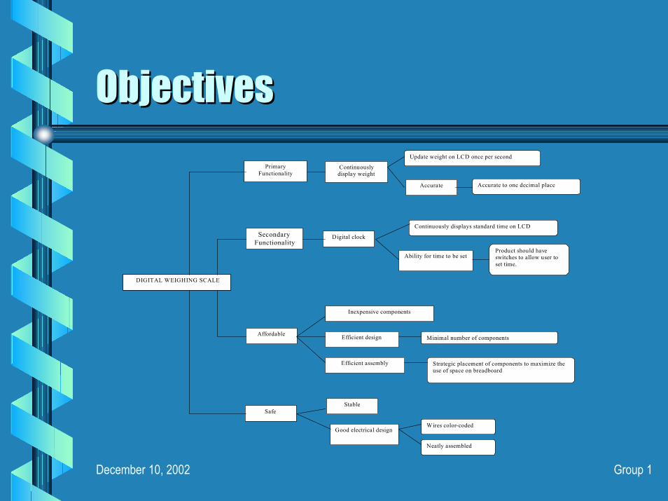
ObjectivesObjectives
DIGITAL WEIGHING SCALE
Accurate
Secondary Functionality
Safe
Affordable
Stable
Good electrical design
Inexpensive compon ents
Efficient design
Efficient assembly
Minimal number of components d
Strategic placement of components to maximize the use of space on breadboard
Wires color-coded
Neatly assembled
Digital clock
Primary Functionality
Continuously displays standard time on LCD
Product should have switches to allow user to set time.
Ability for time to be set
Continuously display weight
Accurate to one decimal place
Update weight on LCD once per second
December 10, 2002 Group 1
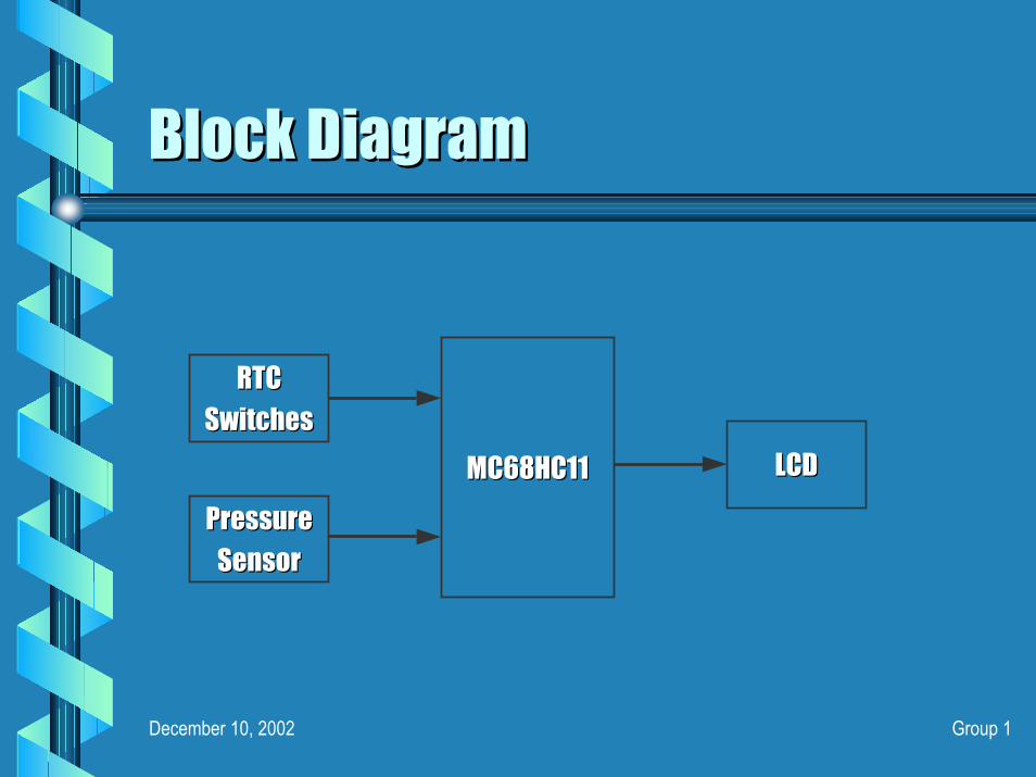
Block DiagramBlock Diagram
MC68HC11MC68HC11
RTCRTCSwitchesSwitches
PressurePressureSensorSensor
LCDLCD

December 10, 2002 Group 1
BackgroundBackground
Prior WorkPrior Work
OSHAOSHA
FCCFCC

December 10, 2002 Group 1
Prior Work Prior Work –– www.uspto.govwww.uspto.govPatent application 20020050412Patent application 20020050412““A lever system (1, 7) for a weighing scale has an electrical traA lever system (1, 7) for a weighing scale has an electrical transducer, nsducer, particularly a strain gauge (14), producing signals correspondinparticularly a strain gauge (14), producing signals corresponding to the amount g to the amount of the weighing load. The transducer is attached to a body (1) tof the weighing load. The transducer is attached to a body (1) that is coupled to hat is coupled to the lever system (1, 7). The lever system (1, 7) includes a meanthe lever system (1, 7). The lever system (1, 7) includes a means (17) for s (17) for receiving a calibration weight (18) in an arrangement where the receiving a calibration weight (18) in an arrangement where the forces forces generated by the calibration weight (18) and/or a damper elementgenerated by the calibration weight (18) and/or a damper element (5, 6) are (5, 6) are magnified.magnified.””
Patent application Patent application 2002008280220020082802““An apparatus and method for weighing and nonAn apparatus and method for weighing and non--contact measuring of contact measuring of dimensions of a stationary object, wherein the platen on which tdimensions of a stationary object, wherein the platen on which the object is he object is placed for weighing and measuring is isolated from the support aplaced for weighing and measuring is isolated from the support assembly for the ssembly for the dimension measuring sensors for greater sensitivity and accuracydimension measuring sensors for greater sensitivity and accuracy in weight in weight determination. A method of determining object speed of linearly determination. A method of determining object speed of linearly inin--motion object, motion object, useful for determining object dimensions, is also disclosed.useful for determining object dimensions, is also disclosed.””

December 10, 2002 Group 1
OSHA OSHA -- www.www.oshaosha.gov.gov1910.303(c)1910.303(c)Splices. Conductors shall be spliced or joined with splicing devSplices. Conductors shall be spliced or joined with splicing devices ices suitable for the use or by brazing, welding, or soldering with asuitable for the use or by brazing, welding, or soldering with a fusible fusible metal or alloy. Soldered splices shall first be so spliced or jometal or alloy. Soldered splices shall first be so spliced or joined as to ined as to be mechanically and electrically secure without solder and then be mechanically and electrically secure without solder and then soldered. All splices and joints and the free ends of conductorssoldered. All splices and joints and the free ends of conductors shall be shall be covered with an insulation equivalent to that of the conductors covered with an insulation equivalent to that of the conductors or with or with an insulating device suitable for the purposean insulating device suitable for the purpose
1910.303(g)(1) 1910.303(g)(1) Working space about electric equipment. Sufficient access and woWorking space about electric equipment. Sufficient access and working rking space shall be provided and maintained about all electric equipmspace shall be provided and maintained about all electric equipment to ent to permit ready and safe operation and maintenance of such equipmenpermit ready and safe operation and maintenance of such equipment.t.

December 10, 2002 Group 1
OSHA OSHA -- www.www.oshaosha.gov.gov1910.305(f)1910.305(f)All conductors used for general wiring shall be insulated unlessAll conductors used for general wiring shall be insulated unlessotherwise permitted in this Subpart. The conductor insulation shotherwise permitted in this Subpart. The conductor insulation shall be of all be of a type that is approved for the voltage, operating temperature, a type that is approved for the voltage, operating temperature, and and location of use. Insulated conductors shall be distinguishable blocation of use. Insulated conductors shall be distinguishable by y appropriate color or other suitable means as being grounded appropriate color or other suitable means as being grounded conductors, ungrounded conductors, or equipment grounding conductors, ungrounded conductors, or equipment grounding conductors.conductors.

December 10, 2002 Group 1
FCC FCC -- www.www.fccfcc.gov.gov
This is a class B digital device, pursuant to Part 15 This is a class B digital device, pursuant to Part 15 of the FCC Rules of the FCC Rules
The device can not cause harmful interferenceThe device can not cause harmful interferenceThe device must accept any interference receivedThe device must accept any interference receivedThese limits are designed to provide reasonable These limits are designed to provide reasonable protection against harmful interference in a residential protection against harmful interference in a residential installation. This equipment generates, uses and can installation. This equipment generates, uses and can radiate radio frequency energy and, if not installed and radiate radio frequency energy and, if not installed and used in accordance with the instructions, may cause used in accordance with the instructions, may cause harmful interference to radio communications.harmful interference to radio communications.

December 10, 2002 Group 1
Mechanical DesignMechanical Design
OverviewOverview
Parts ListParts List
Design AlternativesDesign Alternatives
December 10, 2002 Group 1
OverviewOverview
Final DesignFinal DesignObject is placed on the trayObject is placed on the trayForce is measured through the dowel rod on Force is measured through the dowel rod on the pressure sensorthe pressure sensorThe voltage from the sensor is converted to the The voltage from the sensor is converted to the weight value weight value

December 10, 2002 Group 1
Parts ListParts ListPlastic Project BoxPlastic Project Box22--Metal BushingsMetal Bushings44--screwsscrews22--9V battery clips9V battery clipsWood Dowel RodWood Dowel RodPlastic End CapPlastic End Cap1616--Gauge Sheet MetalGauge Sheet MetalMM--Type Power PlugType Power PlugMM--Type Power JackType Power Jack

December 10, 2002 Group 1
Design AlternativesDesign Alternatives
Use of Spring / Lever MechanismUse of Spring / Lever Mechanism
Using 4 Sensors Using 4 Sensors

December 10, 2002 Group 1
Use of Spring / Lever MechanismUse of Spring / Lever Mechanism
One possible design involved using a lever One possible design involved using a lever and spring mechanism to turn a and spring mechanism to turn a potentiometer with changes in weight.potentiometer with changes in weight.
This design was rejected because of its This design was rejected because of its nonnon--linear response due to the spring’s linear response due to the spring’s behavior. behavior.

December 10, 2002 Group 1
Using 4 SensorsUsing 4 Sensors
Another possible design involved using a Another possible design involved using a plate with 1 leg/sensor in each corner. plate with 1 leg/sensor in each corner.
The data from each sensor would be added The data from each sensor would be added to achieve a more accurate reading. to achieve a more accurate reading.
This idea was rejected because of the This idea was rejected because of the expensive nature of the sensors.expensive nature of the sensors.

December 10, 2002 Group 1
HardwareHardware
Components UtilizedComponents Utilized
SchematicsSchematics
December 10, 2002 Group 1
Components UtilizedComponents Utilized
MC68HC11 MC68HC11 microprocessormicroprocessorEvaluation BoardEvaluation BoardFlexiFlexi--force force Pressure SensorPressure SensorLM 741LM 741 OpOp--AmpAmpPotentiometer
ResistorsResistors33--SwitchesSwitches9 volt batteries9 volt batteriesLCDLCDWiresWires
Potentiometer

December 10, 2002 Group 1
FlexiFlexi--force Pressure Sensorforce Pressure Sensor
The FlexiThe Flexi--force single element sensor acts as a resistor in an electrical force single element sensor acts as a resistor in an electrical circuit.circuit. When the sensor is unloaded, its resistance is very high.When the sensor is unloaded, its resistance is very high. When a force When a force is applied to the sensor, this resistance decreases.is applied to the sensor, this resistance decreases.
Physical PropertiesPhysical Properties::Thickness: 0.005" (0.127 mm) Thickness: 0.005" (0.127 mm) Length: 8.000" (203 mm) Length: 8.000" (203 mm) -- End of connector to tip of sensor End of connector to tip of sensor Width: 0.55" (14 mm) Width: 0.55" (14 mm) Active Sensing Area: 0.375" (10 mm) diameter Active Sensing Area: 0.375" (10 mm) diameter Connector: 3 pin Berg ClincherConnector: 3 pin Berg Clincher
December 10, 2002 Group 1
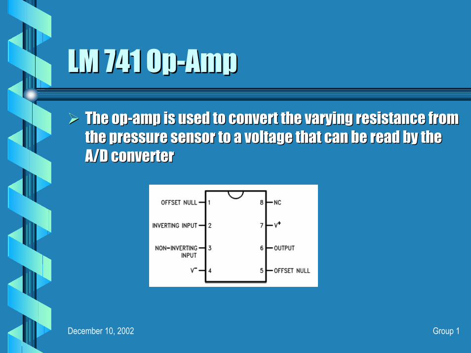
LM 741LM 741 OpOp--AmpAmpThe opThe op--amp is used to convert the varying resistance from amp is used to convert the varying resistance from the pressure sensor to a voltage that can be read by the the pressure sensor to a voltage that can be read by the A/D converterA/D converter
December 10, 2002 Group 1
SchematicsSchematics
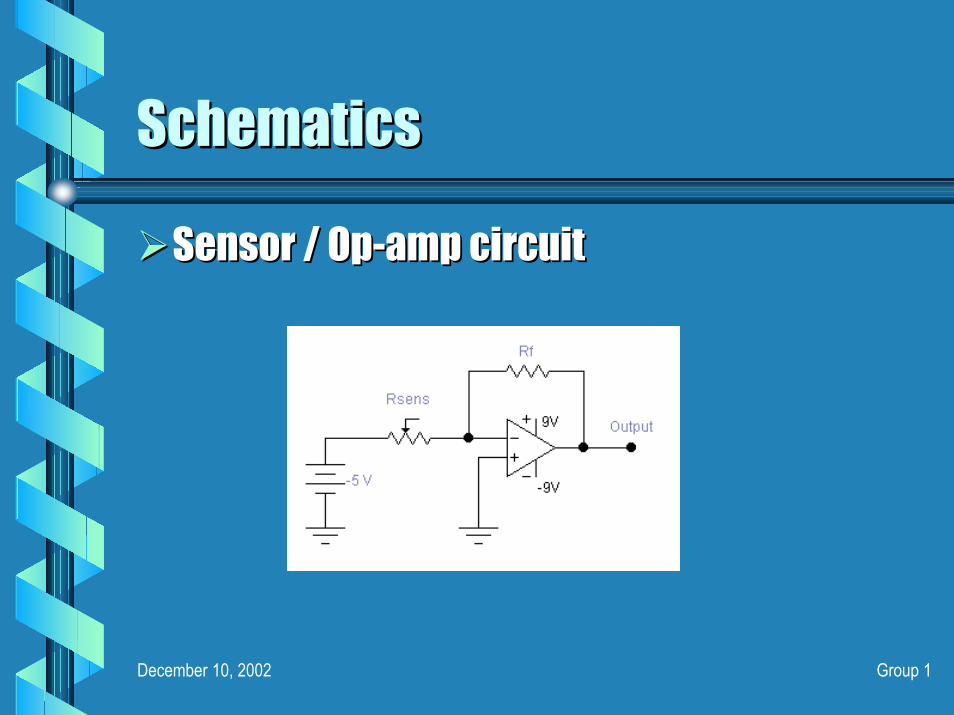
Sensor / OpSensor / Op--amp circuitamp circuit
December 10, 2002 Group 1
SchematicsSchematics
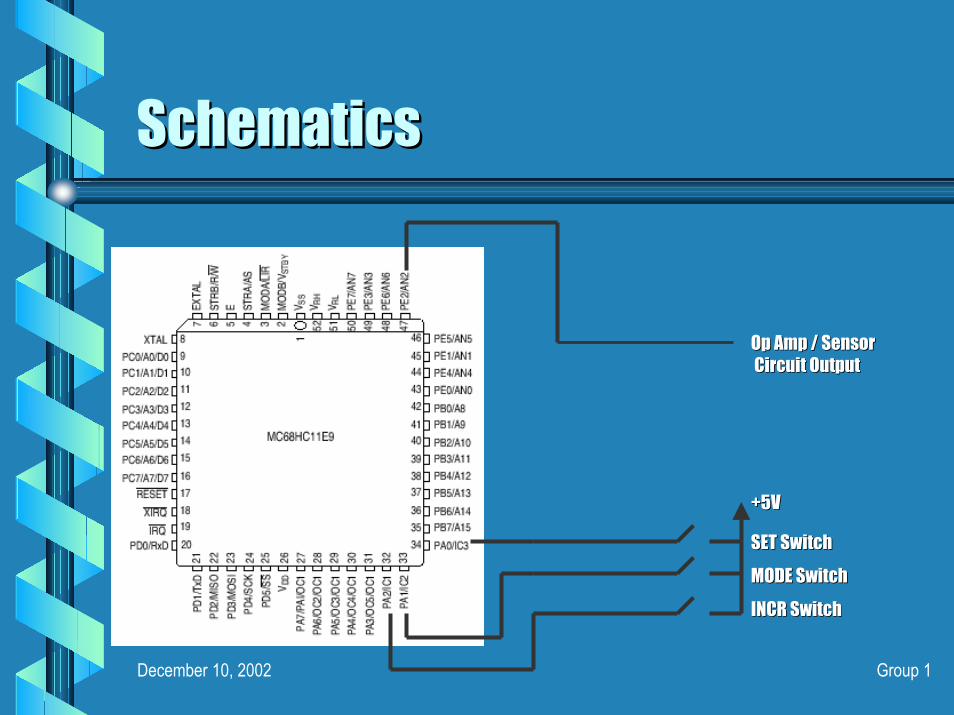
Op Amp / SensorOp Amp / SensorCircuit OutputCircuit Output
+5V+5V
SET Switch SET Switch MODE SwitchMODE SwitchINCR SwitchINCR Switch

December 10, 2002 Group 1
SoftwareSoftware
Overview ChartOverview ChartA/DA/DLookLook--Up TableUp TableReal Time ClockReal Time ClockDisplaying & Processing DataDisplaying & Processing Data
Whole NumberWhole NumberDecimal NumberDecimal Number

December 10, 2002 Group 1
Overview ChartOverview Chart
Collect 4 samplesCollect 4 samplesfrom AN2/PE2from AN2/PE2
Configure A/D Configure A/D ConverterConverter Check If CCFCheck If CCF
Is setIs set
Average the Average the samplessamples
Look upLook upcorrespondingcorrespondingweight in tableweight in table
Separate weightSeparate weightinto whole andinto whole and
decimal partdecimal part
Save whole andSave whole anddecimal partsdecimal parts
NOTE: The weight is displayed in the ‘second’ routineNOTE: The weight is displayed in the ‘second’ routine

December 10, 2002 Group 1
A/D ConversionA/D Conversion
Bit pattern to written into ADCTLBit pattern to written into ADCTLBitBit--7 = Don't care because it's a read only bit 7 = Don't care because it's a read only bit BitBit--5 = 0 for Non5 = 0 for Non--scan mode scan mode BitBit--4 = 0 for Single4 = 0 for Single--channel modechannel modeBitBit--3, Bit3, Bit--2, Bit2, Bit--1 and Bit1 and Bit--0 = 0 0 1 0 (to select AN2)0 = 0 0 1 0 (to select AN2)
December 10, 2002 Group 1
LookLook--Up TableUp Table
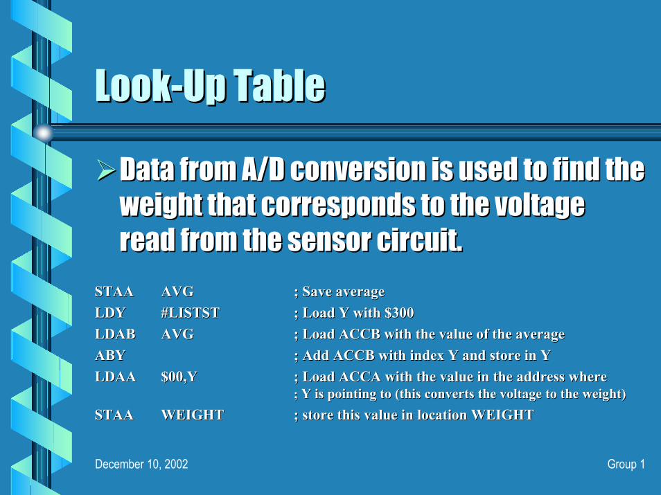
Data from A/D conversion is used to find the Data from A/D conversion is used to find the weight that corresponds to the voltage weight that corresponds to the voltage read from the sensor circuit.read from the sensor circuit.
STAASTAA AVGAVG ; Save average; Save averageLDYLDY #LISTST#LISTST ; Load Y with $300; Load Y with $300LDABLDAB AVGAVG ; Load ACCB with the value of the average; Load ACCB with the value of the averageABYABY ; Add ACCB with index Y and store in Y; Add ACCB with index Y and store in YLDAA LDAA $00,Y$00,Y ; Load ACCA with the value in the address where ; Load ACCA with the value in the address where
; ; Y is pointing to (this converts the voltage to the weight)Y is pointing to (this converts the voltage to the weight)STAASTAA WEIGHTWEIGHT ; store this value in location WEIGHT; store this value in location WEIGHT
December 10, 2002 Group 1
Processing DataProcessing Data
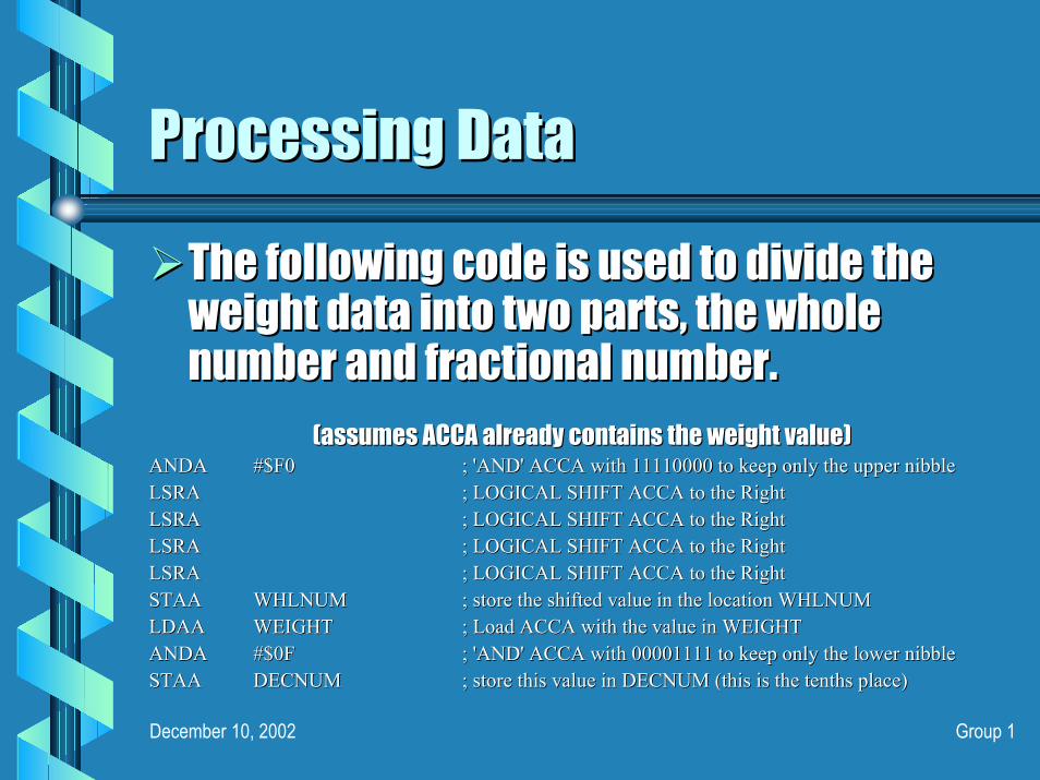
The following code is used to divide the The following code is used to divide the weight data into two parts, the whole weight data into two parts, the whole number and fractional number.number and fractional number.
(assumes ACCA already contains the weight value)(assumes ACCA already contains the weight value)ANDAANDA #$F0#$F0 ; 'AND' ACCA with 11110000 to keep only the upper nibble; 'AND' ACCA with 11110000 to keep only the upper nibbleLSRALSRA ; LOGICAL SHIFT ACCA to the Right; LOGICAL SHIFT ACCA to the RightLSRALSRA ; LOGICAL SHIFT ACCA to the Right; LOGICAL SHIFT ACCA to the RightLSRALSRA ; LOGICAL SHIFT ACCA to the Right; LOGICAL SHIFT ACCA to the RightLSRALSRA ; LOGICAL SHIFT ACCA to the Right; LOGICAL SHIFT ACCA to the RightSTAASTAA WHLNUMWHLNUM ; store the shifted value in the location WHLNUM ; store the shifted value in the location WHLNUM LDAALDAA WEIGHTWEIGHT ; Load ACCA with the value in WEIGHT; Load ACCA with the value in WEIGHTANDAANDA #$0F#$0F ; 'AND' ACCA with 00001111 to keep only the lower nibble; 'AND' ACCA with 00001111 to keep only the lower nibbleSTAASTAA DECNUM DECNUM ; store this value in DECNUM (this is the tenths place); store this value in DECNUM (this is the tenths place)
December 10, 2002 Group 1
Displaying DataDisplaying Data
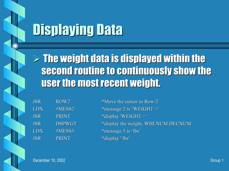
The weight data is displayed within the The weight data is displayed within the second routine to continuously show the second routine to continuously show the user the most recent weight. user the most recent weight.
JSRJSR ROW2ROW2 *Move the cursor to Row*Move the cursor to Row--22LDXLDX #MESS2#MESS2 *message 2 is *message 2 is ‘‘WEIGHT =WEIGHT =‘‘JSR JSR PRINTPRINT *display 'WEIGHT = '*display 'WEIGHT = 'JSRJSR DSPWGTDSPWGT *display the weight, WHLNUM.DECNUM*display the weight, WHLNUM.DECNUMLDXLDX #MESS3#MESS3 *message 3 is *message 3 is ‘‘lbslbs’’JSRJSR PRINTPRINT *display ' lbs' *display ' lbs'

December 10, 2002 Group 1
CalibrationCalibration
Hardware Hardware
SoftwareSoftware
December 10, 2002 Group 1
Hardware CalibrationHardware Calibration
The feedback resistor in the opThe feedback resistor in the op--amp circuit amp circuit must be adjusted to give a desired voltage must be adjusted to give a desired voltage output when a 5 lb weight is placed on the output when a 5 lb weight is placed on the scale.scale.
Appropriate VAppropriate VRH and RH and VVRLRL levels must be levels must be applied to the A/D pins of the micro.applied to the A/D pins of the micro.

December 10, 2002 Group 1
Software CalibrationSoftware Calibration
The lookThe look--up table must be adjusted so that up table must be adjusted so that the scale accurately display the weight the scale accurately display the weight from 0from 0--5 lbs, given the A/D resolution 5 lbs, given the A/D resolution determined by the Hardware Calibration.determined by the Hardware Calibration.
The lookThe look--up table must be shifted so that up table must be shifted so that 0 lbs is displayed when only the weight of 0 lbs is displayed when only the weight of the tray is present.the tray is present.

December 10, 2002 Group 1
Operating ProcedureOperating Procedure
ScaleScaleContinuous ReadContinuous Read--outout
RTCRTC3 switches 3 switches

December 10, 2002 Group 1
Cost AnalysisCost Analysis

December 10, 2002 Group 1
Problems EncounteredProblems Encountered
Reselection of ProjectReselection of ProjectCalibrationCalibrationMechanicsMechanics
December 10, 2002 Group 1
Reselection of ProjectReselection of Project
Originally assigned to design current and Originally assigned to design current and voltage monitoring system for the voltage monitoring system for the WSU Solar Car ProjectWSU Solar Car Project
Unavailability of sensors Unavailability of sensors Unavailability of 150V Unavailability of 150V –– 5V DC/DC Converter5V DC/DC Converter
This resulted in setting us back a few This resulted in setting us back a few weeks for our weighing scaleweeks for our weighing scale

December 10, 2002 Group 1
CalibrationCalibration
Difficulty in determining an appropriate Difficulty in determining an appropriate value for the feedback resistorvalue for the feedback resistor
Used potentiometerUsed potentiometer
Sensor conditioning required: leads to Sensor conditioning required: leads to instability and noninstability and non--linearity of sensor linearity of sensor responseresponse
Currently conditioning sensorCurrently conditioning sensor
December 10, 2002 Group 1
MechanicsMechanicsUse of metal rod creates a lot of friction in the Use of metal rod creates a lot of friction in the bushing bushing
Used wooden dowel rod insteadUsed wooden dowel rod instead
Keeping the rod verticalKeeping the rod verticalUsed two 1Used two 1--inch bushings to stabilize inch bushings to stabilize
Keeping consistent contact with pressure sensorKeeping consistent contact with pressure sensorAdded flat end cap for bottom of dowel rodAdded flat end cap for bottom of dowel rod

December 10, 2002 Group 1
Work BreakdownWork Breakdown

December 10, 2002 Group 1
ConclusionConclusion
We are still working on calibrating the We are still working on calibrating the scale right now. scale right now.
The real time clock and all the other The real time clock and all the other software works, we are just limited by the software works, we are just limited by the mechanical interface at this point. mechanical interface at this point.

December 10, 2002 Group 1
Questions . . .Questions . . .