dimensional inspection planning based on product data
TRANSCRIPT

U.S. DEPARTMENT OF COMMERCENarional Institute of Standards and Technology
National PDFS Testbed
Report Series
DimensionalInspectionPlanning Based onProduct DataStandards
NATIONAL
.U56
//5183
19S5


NiSTIR 5183
National PDES Testbed
Report Series
NATIONAL
I
TESTBED TM
U.S. Department of Commerce
Ronald H. Brown,
Secretary
National Institute of
Standards and Technology
Raymond G. Kammer, acting
Director
May 18, 1993
DimensionalInspection
Planning Basedon Product DataStandards
Shaw C. Feng
i
%

Ilf'.;*
I
' h.t-
;'v
;';
'
'?r,..^/'-
'
, *i4'•••''•:. .M'.Vo-j; i
iCv
k’-^.v; .' .'•. <'
,
’•
,
•'.-
-V.'-'v•• ,VA; V,,,.
.'•
, -i'-j . -^ •^r ,'•*' '4'
'W.;
i'J ii:' /• •
, ••''s’ •'^'
f K
u
:Si;|J'^
-I*,'•«.'«'
;>i
Vii';
’V'
*
R? - I''! ''!•
't 'jVvi-'jT-gCT
,!r''''”,. x' '.; (
. .•mm
..v".'-', i‘
VAsl”'?
i1'
.
y*''' K' 4i‘" •’P^'y

Contents
Abstract 1
1 Introduction 1
2 Review of Fundamental Standards and Methodologies for Dimensional Inspection
Planning 2
2.1 Product Data Exchange Standards 3
2.1.1 Product data representation and exchange standardization 3
2.1.2 Measurement data exchange standardization 5
2.2 Process Planning Methodologies 6
2.3 Dimensional Inspection Planning Methodologies 6
3 Inspection Planning Activities 7
3.1 Glossary for Inspection Planning Activity Model 8
3.2 Inspection Planning Activity Model 12
4 Conclusion 23
Acknowledgement 24
5 References 25
APPENDIX A 27

[* I A i 0 ‘>vr-
VI Jills',^Ny'-'%'''{^'' '."I'iMp,
-)'
i^-.' ;
* V ',‘
r -^ rr - --
• ' #' <f^'m. .. ..
Jri'f ^
•,' ''s'-' 'v'''
...... .
’
..':
,•. . ; ',v . . :
,. s£.i-§o^jWj»^N5
;.. 4 ssi5^i/
... . ; .
*') '. '^ s' "- ''
‘"''.- - .'r/Cw.'.?:*.
v:
»,'•
,, «... ..
.."...
‘. :A W[fl>t3«A. :.-':«^
.', . ';.V... --r.-. •.:*•. .. Sailii..V.'. .V »•» .. Sa_mm
'‘'fr 'll-".i'h i/ : fiSSilLiS'
' ‘
'>l<

Dimensional Inspection Planning Based on Product Data Standards^
Shaw C. Feng
Factory Automation Systems Division
Manufacturing Engineering Laboratory
National Institute of Standards and Technology
Gaithersburg, Maryland 20899
Abstract
An international standard on product data representation and exchange for dimensional inspection
planning is being developed. This paper provides a review of fundamental technology enabling
the standard development and describes the current status of an activity model. The model
defines functional requirements of the standard. A set of diagrams has been generated to
represent the activity and its sub-activities, inputs, outputs, controls and mechanisms, when such
planning is based on technologies of product data exchange, process planning and information
modeling.
Key Words: activity modeling, DMIS, dimensional inspection, information modeling, process planning, STEP
1 Introduction
This paper describes the current status and future development of a proposed international
standard, ISO 10303 Application Protocol (AP) for "Dimensional Inspection Plan for Coordinate
Measuring Using Tactile and Video Sensors", which is part of the work within ISO Technical
Committee 184 (Industrial Automation Systems and Integration), Subcommittee 4 (Industrial Data
and Global Manufacturing Programming Languages). ISO 10303 [1], known as STEP (Standard
for Exchange of Product Model Data), is an international standard, currently under development,
for computer representation and exchange of product models. The STEP standard includes parts
called Application Protocols [2] that support product life-cycle applications to access product
model data and exchange them between different systems.
DMIS (Dimensional Measuring Interface Standard) [3] is a U.S. national standard that provides
interface formats for linking computer aided design (CAD) systems and coordinate measuring
machines (CMMs). The formats are data structures for specifying inspection-related data, such
as part geometry, features, tolerances, measuring device configurations, process parameters and
actual measured values. The linkage is established by the smooth exchange of inspection-related
data between different CAD systems and CMMs.
*This work has been conducted in the AP for Inspection Planning Project which is one of the projects within the
National PDES Testbed Program. Funding for this project was provided by NIST.
1
Dimensional inspection planning is an activity to generate specific inspection instructions to
inspect manufactured parts based on the product design. Properly developed inspection plans will
ensure consistency of measurement results. An inspection-planning STEP AP is necessary to
enable inspection planners and product designers to effectively communicate during product
design and inspection process planning.
Industries, such as aerospace, automotive and machinery industries, have a critical need for
improving quality of manufactured parts through inspection. These industries currently use two-
dimensional drawings to represent the product design in most cases. Process plans and inspection
plans are in paper form. Machine control programs are usually entered manually into CMMs and
vision systems. This is time consuming, error prone, and labor intensive. A more cost effective
means is urgently needed. A standard model for product data representation will enable the
generation of a common enterprise database which will integrate the design, process planning,
manufacturing, and inspection processes.
The objective of this AP is to specify information requirements for exchange and use of STEPfor dimensional inspection planning when manufactured parts are inspected using CMMs and
vision systems. This AP will provide data structures for generating DMIS inspection programs.
This AP will allow industry to effectively apply STEP-based technology in measurement and
inspection functions. The relationship between inspection planning, STEP and DMIS is
graphically presented in Figure 1.
This paper presents an activity model of the dimensional inspection planning process. The model
defines functional requirements of the standard and is one of the elements of the AP. The model
is documented using the IDEFO methodology [4]. Other elements of the AP are currently under
development.
This report has four sections, including this introduction. Section 2 is a review of the
fundamental technology which facilitates inspection planning based on STEP and DMIS. Section
3 describes the inspection planning activity model shown in an IDEFO diagram. Section 4
summarizes the work and describes future work. Appendix A includes a summary of the AP as
it was proposed.
2 Review of Fundamental Standards and Methodologies for Dimensional Inspection
Planning
Product data exchange standards and process planning methodologies have enabled AP developers
to develop an inspection planning information model. Process planning methodologies provide
the means to efficiently generate process plans that are consistent and effective. Standards
provide common language and data formats to exchange plans between different application
systems.
2

Figure 1 Inspection Planning Data Based on STEP
2.1 Product Data Exchange Standards
This section describes basic functions and structures of the STEP and DMIS standards. These
two standards together provide a resource of data models for the planning of inspection processes.
2.1.1 Product data representation and exchange standardization
STEP provides a data model capable of capturing product information necessary to applications
throughout a product’s life cycle. Product data is a general term used to refer to some or all of
the pieces of information captured in the model. Product data includes shape definitions,
properties of a product, assembly of the product, and application-specific constraints to the data.
Examples of product data are geometry, topology, material, dimensions, tolerances and assembled
structure. Application protocols are composed of specifications of information requirements for
application domains to define and use the generic data model. The objective of STEP is to
provide a mechanism to clearly, unambiguously and completely represent products. Industries
use the product data to develop product models and process plans in an integrated manufacturing
environment.
The fundamental structure of STEP, represented in Figure 2, has six major components:
principles, implementation methods, description methods, conformance testing methods, integrated
3

resources and application protocols. Integrated resources have two sub-components: generic
resources and application resources. Tools and systems support the standard development
processes by providing a means for standards developers to analyze and test the draft standard.
The users’ requirements, provided by industry, form the basis on which the standard is structured
and developed. STEP can be used for computer aided applications built in commercial systems.
The principles of STEP are described in the draft ISO 10303 Part 1 [1] which provides an
overview and the fundamental principles on which STEP is based.
The description methods are rules for defining data and their relationships suitable for
communication, interpretation and processing by computers. The descriptive language of STEP,
named EXPRESS [5], is a computer language specifying the integrated resources and application
protocols.
The implementation methods specify techniques to use, exchange and access STEP information
models of an application protocol. There are three implementation methods: physical file
exchange, direct access and database access. The physical file, where data are stored, exchange
allows for reading and writing product data of an application into a computer-interpretable file
for storing, accessing and transmitting. The direct access allows applications to directly use the
data specified in the application protocols. Database, where data are stored, access allows the
4

exchange of product data through databases whose internal data models are determined by the
application interpreted models (AIM) [2] of application protocols. An AIM is developed from
an application reference model [2] which fully specifies the data required in an application
domain.
Test methods are specified in STEP to test implementations for conformance to an AP. Aconformance test is based upon a complete set of test cases called an abstract test suite that must
be sufficient to test implementations according to the requirements of the application protocol.
The conformance tests are used for testing any implementation claiming to support an application
protocol’s requirements.
The integrated resources are data models for representing products across applications. The
integrated resources are divided into two separate groups: generic resources and application
resources. The generic resources capture the commonality of products and are independent of
all applications. The application resources define data models for related groups of applications.
The application resources reference and extend the generic resources to suit requirements of
related applications.
The application protocols specialize the integrated resources to meet the information requirements
of specific applications with defined scopes and function requirements. The specialization is
achieved by selecting the appropriate integrated resources, refining their meaning and specifying
any appropriate constraints. This specialization is known as interpretation and results in an
application interpreted model. The procedure to develop an application protocol consists of the
following eight steps: specification of the application context, scope and information
requirements; development of an activity model; development of an application reference model;
development of an application interpreted model; and development of a test suite.
The activity model in this paper is defined by the application context of dimensional inspection
planning. Based on the defined context, the AP refines the integrated resource models by
specifying necessary constraints to specialize the models to meet the requirements of dimensional
inspection planning.
2.1.2 Measurement data exchange standardization
Similar to STEP, but with smaller scope, DMIS provides neutral formats for the exchange of
some part design data, inspection data and measured values of manufactured parts between CADsystems and coordinate measurement systems. DMIS specifies data structures of information on
part design and the inspection process (dimensions, tolerances, features of discrete manufactured
parts, inspection process parameters and measurement results such as actual dimensions and
tolerances of features). Like STEP, DMIS is computer interpretable as well as human
interpretable. However, there is currently no link between STEP and DMIS.
5

The STEP Application Protocol for Inspection Planning is being developed to provide an
informational link between STEP and DMIS. Operating in a STEP environment, inspection
planners access part design information in STEP to generate data structures in DMIS.
2.2 Process Planning Methodologies
Process planning [7, 8, 9] is an activity to devise means and specify instructions for
manufacturing parts to achieve productivity and quality goals under given constraints of limited
resources. The quality goals are specified in product design. For example, in a machining
process plan, specific activities include selection of machine tools, selection of cutters,
determination of set-ups, determination of machining operations and their sequence, calculation
of cutting conditions, generation of tool paths and generation of NC programs. Specific goals
include manufacturing parts to be within tolerances and surface conditions specified in the design,
optimizing process parameters, reducing the number of scrap parts and increasing productivity.
Computer aided process planning (CAPP) provides flexible ways of generating process plans.
CAPP is based on knowledge acquisition and processing technology which aids the planning
activities to generate more consistent and effective plans than the ones created manually. There
are three major approaches in CAPP: variant, generative, and semi-generative. The variant
approach is based on group technology. In group technology, various similar parts are grouped
together and a coding system is developed to describe the relationships of parts in and between
groups. Standard process plans are first developed and stored in a computer for groups. A new
part will be given a code to show which group of parts it belongs in and then a standard process
plan is retrieved and modified to suit the new part. The generative approach is to automatically
synthesize the process information to develop a plan for a part directly from the part model and
process logic. The manufacturing knowledge, manufacturing process databases (containing data
on machines and their capabilities, tools, jigs, fixtures, etc.) and process planning algorithms are
stored in the computer and used when a new part model is available. The semi-generative
approach combines both the variant approach and the generative approach. For a new part coded
according to group technology, a standard plan is first retrieved. The retrieved plan is then
modified and completed using a generative approach.
The technology developed for process planning can be applied to inspection planning. The
generative approach allows knowledge acquisition and reasoning to be applied to inspection
planning. The main difference lies in the nature of the process planning logic.
2.3 Dimensional Inspection Planning Methodologies
This section provides a review of existing inspection planning methods.
Hopp and Lau [10] developed a hierarchical model and surface decomposition method for
automated inspection. In this approach, toleranced features to be inspected are decomposed into
datum features and inspection features. A datum feature can be a compound feature. Similarly,
an inspection feature can be a composite feature. Compound datum features and composite
6

features are decomposed into simple features (individual surfaces). Probing points and probing
paths are then generated on the surfaces of features for inspecting the feature and surfaces of
datum features for establishing datums. This tolerance decomposition technique provides a basis
for dealing with toleranced features in inspection planning.
ElMaraghy and Gu [11] and Menq, Wang and Yao [12] developed methods to integrate a
knowledge based capability into an inspection planning system to prove the concept of using a
generative approach in inspection planning. Properties of manufactured features to be inspected
are represented. Rules for the extraction of information from feature representations, the
selection of CMM and the determination of measurement sequence are implemented.
Knowledge-based inspection allows automatic decision-making for creating consistent plans.
Brown and Gyorog [13] developed an activity model for inspecting parts using CMMs with
touch-trigger probes. The activity model is an IDEFO diagram which represents input, output,
control and mechanism (resource) data and planning activities. This work applies information
modeling techniques to define and describe relationships between activities and data.
Applying video sensor technology to part inspection can increase the throughput and the
flexibility of inspection. Vision-based inspection planning systems [14] that have video sensors
are currently under development. The inspection planning capabDities include planning the
inspection path, generation of a nominal image of the part, and determination of cameras and
process parameters.
Inspection planning technology has been evolving. Methodologies has been developed in the
areas of automatic tolerance decomposition, utilization of knowledge acquisition and processing
capability, and modeling the information required in inspection process planning. For a
successful dimensional inspection planning task, a part model must provide the necessary
geometrical and functional descriptions of the part. STEP provides these descriptions.
Knowledge acquisition and knowledge processing capabilities provide efficient and consistent
planning. Knowledge-based technology assists process planners to best use the existing
experience. The knowledge should include manufacturing process knowledge, inspection
knowledge and resource utilization knowledge. DMIS provides a basis for transferring inspection
plan data to dimensional measuring machines. Integration of CMM simulation with CADsystems facilitates verification of planned inspection paths.
3 Inspection Planning Activities
This section describes an inspection planning activity developed and proposed by us for the
development of a STEP Application Protocol for Inspection Planning. This model, developed
using IDEFO, specifies activities and data for inspection planning based on STEP and DMIS.
A glossary for the model has also been developed.
7

3.1 Glossary for Inspection Planning Activity Model
Change request:
A request made by an inspection plan validator to change a draft inspection plan.
Clamping specifications:
Data that specify how a part is clamped on a machine table. Data include specifications of
clamping devices, clamping method to be used during inspection, clamping configurations,
the sequence of clamping configurations, etc.
Data analysis functions:
Mathematical functions that analyze measured data points to evaluate actual dimensions and
tolerances of the parts, or algorithms for image processing using the vision system.
Decomposed tolerance:
Measurable surfaces which are decomposed from a tolerance. A structure of decomposed
tolerance is shown in Figure 3.
8

Design data:
The product model data representing the part design which includes the following models:
geometry, topology, tolerance, form feature, product functionality, and surface conditions.
Dimensional inspection plan:
Inspection process plan for checking tolerances and features of parts.
Dimensional inspection planning:
Activity to generate dimensional inspection plan.
Dimensional inspection standards:
Standards deal with dimensional inspection methods such as ANSI B89.3.2 Dimensional
Measuring Method, ANSI/ASQC E-2 Guide to Inspection Planning.
DME (Dimensional Measurement Equipment):
Equipment that is used for measurement such as measuring machines, sensors (defined in
DMIS), and mathematical functions for calculating actual features and actual tolerances.
DMIS:Dimensional Measuring Interface Standard, ANSI/CAM-I 101.
Draft inspection plan:
An inspection plan developed by an inspection planner subject to change by an inspection
validator.
Fixture specifications:
Data that specifies fixtures to be used during inspection.
Fixture synthesis system:
A system that designs fixtures for an inspection process.
GD&T standards:
Geometric dimensioning and tolerancing standards, such as ISO 1101, 286-1, 286-2, 8015,
etc. and ANSI Y14.5.
Inspection accuracy requirement:
Specification of the interval of uncertainty associated with each measurement, level of
confidence on the substitute feature, and magnitudes of pass error and fail error on the
inspected tolerance.
Inspection knowledge:
Knowledge for determining how parts should be inspected.
9

Inspection method:
Detailed specification about how to measure parts (e.g., determination of points to measure,
specifications of process parameters, selection of data analysis algorithms).
Inspection plan:
A document of detailed instructions to inspect parts using design model data as input.
Contents of the document includes inspection scope, accuracy requirements, specification of
appropriate dimensional measurement equipment, part set-up, step-by-step inspection
instruction, and plan validation.
Inspection plan validator:
A person or software function that check the validity of a draft inspection plan and makes
the decision to approve, disapprove, or request changes to the draft inspection plan.
Inspection planner:
A person or software function that uses an inspection planning system to generates inspection
plans.
Inspection planning system:
A computer system used to assist an inspection planner to generate inspection plans.
Inspection process parameter:
A factor that determines how an inspection process should be performed. Process parameter
can be machine parameter or sensor parameter. A process parameter can be machine speed,
measuring speed, machine operation mode, sensor orientation, sensor size, etc.
Inspection scope:
Specification of what toleranced features should be verified.
Inspection simulation system:
A system that generates simulated machine and probe motion relative to the part for
verification.
Inspection type:
Two types of inspection are possible: in-process inspection and final part inspection. In-
process inspection includes on-machine inspection and between-workstation inspection. In-
process inspection is for monitoring, correcting, and controlling manufacturing processes.
Final inspection determines conformance of parts to design specification. A "global"
inspection of a part can be also performed to check the completeness of all the machined
features before the in-process or the final inspection.
Manufacturing process knowledge:
Knowledge on what kinds of form error can be produced from a manufacturing process.
10

Measuring sequence:
Order of going through different part orientations; order of measuring tolerances in a specific
orientation, surfaces of a tolerance, points on a surface. See Figure 4.
Measuring Sequence
Part Orientation
Tolerance Tol.
Feature Feat.
Surface Surf.
Proc. par.Proc.
par.
Meas. pts.Trans.
Proc. par.
pts.
Meas. pts.
Proc.
par.
Trans.
pts.
Proc.
par.
Trans.
pts.
Rgure 4 Measuring Sequence
Proc.
par.
Transpts.
Regulations and policies:
Rules to regulate the inspection plan validation and approval process.
Selected DME:The measuring machine(s), sensor(s), and data analysis function(s) that are chosen by the
inspection planner for dimensional inspection of parts.
Selected tolerances:
Tolerances that are selected by the inspection planner and needed to be inspected.
Sensor:
A device used in inspection to collect dimensional information for a part. Sensors include
(but are not limited to) the following device types: touch-trigger probe, analog contact probe,
laser probe, vision (video sensing) system and capacitance probe.
11

Support data:
A general term for orders of fixtures, probes and probe accessaries, clamps, machines and
other resources needed for inspection.
Support document guidelines:
Rules, policies and procedures that guide inspection planners to generate support data.
Tolerance:
A data structure specifying a tolerance type, tolerance value, applicable tolerance modifiers
(material condition, projected zone, etc.), the toleranced feature (either composite feature or
simple feature) and, for certain tolerance types, the datum reference frame.
Tolerance extractor:
A mechanism that examines the design and pulls out tolerances and their underlying features
from a STEP model of a part.
3.2 Inspection Planning Activity Model
This section presents a model of inspection planning activities. The activity model, represented
using IDEFO, describes inspection planning using STEP and DMIS. The model defines the scope
and functional requirements of the STEP Application Protocol for Inspection Planning. The
IDEFO model is represented by eight diagrams showing activities at different levels of
abstraction. The diagrams shown on the next eight pages are named A-0, AO, Al, A3, A4, A41,
A42 and A43.
Diagram A-0 models the context in which the inspection planning activity takes place. The
activity has inputs of design data from the STEP product model, resource data from the DMEdatabase, inspection type data and in-process shape information from the manufacturing process
plan. The activity also requires controls of knowledge information of manufacturing process and
inspection knowledge, dimensional inspection standards, DMIS, dimensioning and tolerancing
standards, company policies, and guidelines for generating support data. Mechanisms of the
activity are systems and personnel that support the activity and supply needed data. They include
an inspection simulation system, inspection plan validator, inspection planning system, knowledge
based system, database system, inspection planner and fixture synthesis system. The outputs of
the inspection planning activity are (1) an inspection plan, (2) data structures for generating
DMIS inspection programs, and (3) optional support data.
The overall activity on level A-0 is decomposed into five activities (Al — A5) in Diagram AO.
The AO diagram shows the relationship between activities and data inherited from the upper level
(A-0).
Activity Al, shown on diagram AO and expanded in diagram Al, identifies what tolerances,
dimensions and features (toleranced or untoleranced) are within the scope of the part inspection.
12

z ao 0CJ H
uH<Q
CCU§s
Q zCO oQ M2 H
CO <z CJt-( H M
Cl. oct < c; CQo 2 Ds Q 2 CU
X
E0)
Q.<U
CO
CO ..
>< COQ a: o
a\
ifi
(0 000}
</i y5 E r-
Q.Q.O
o> V£)
0) C>Vo
ccre
IT)
Q.< a.
cV
c o.2
mo s0} Q. CMQ. (/)
</) cc.. HQC CJ • •
o CO wz COH o HD 0^ o< a z
(0
13
Inspection
Simulation
System

READER
DATE
a 2cc OO M2 H
CJ M <2 g UM H l?i M2 Cu o 1^QC C) CQo 2 DX Q 2 04
X
CMOi
0)
JDE0Q.0CO
u ••
6-1 >< blQ 2
(/>
w0
00
20.O) V£>
c
i >n
ss0. ^coo0Q.
HUCi]
1^3
oa:
00
<N
touHoz
14
Perform
Dimensional
Inspection
Planning

s
Ou
uH<Q
C\J
O)wQ}nE0)
Q.<V
CO
Cd ..
t-l >< cqQ a
c/>
M0)
C3)C’ccro
Q.
c0
1o.in
HUUID
Oq:
(N
COCl)
HO2
o>
$oc
CO(Oo
0.
O)c
t3ca
cOJ
(A2CODCCD
COI-ofl
oo
H<aCi]
CO2
Eo7n>NCOT3OtoCO
CD
<uO)T3O
Oc
to
4J
"cr(D
oc
>,uTO
MDUO<T3CTO
Cl]
QO2
15
Inspection
Planning
System
Inspection
Planner

ou
uH<O
(Mp>w0}£3EBQ.0)
CO
m ..
H >< uQ Oi
Ol
OS,
oXHD<
(0(/)
00
0)
8£0.
O)VO
cc ir>cre
0.
co ro
ore
<N1Q.(/>
cfH
E-i
U • •
U COu
o Hcc ocu 2
H
lujCD 2CO o
<uccTO
0.
O<uQ.(O
E<u
M>.CO
oa>
re
CD
<DO)o$oc
00*5
DUCOD
UQO2
16
Select
Dimensional
Measuring
Ecjulpment
anci
Funct

flXuHzou
ue-i
<Q
CMP>wOnE
Q.0}
CO
Cd ••
H >< CdQ 2
(ACAOoo
C3)
cro
cgo0}Q.(Ac
E-I
UCd
Oa;cu
CO
r-
VO
m
V
ro
CM
CACdHOz
E-I
<aCdCAD
ro"3
CO CO
S E
QiCd
Z
cra*HCh
to
(0
(1)
uouOu
co•H4J
U(1)
ato
c
ao
ID
>(D
Q
Cd
HME-I
'T
<
CdQOZ
17

CVJ
O)
Q>aEBQ.CD
CO
uH ><Q 2 o
fH
<n(/)
CO
CDoOCL
C3>cc tncCO
CL
c.2 00
oCD
CMQ.(OC
• . Hcc U • •
o u CAa: UH o HD cc: O< CU 2
V)co
oC3)
c.2o0)Q.(AC
CCO
u0}
Q.CAc
18
U3HZou
uH«CQ
a:u§§
Q zU oQ M2 H
o u <z g OM H M
o 1-3
uo 5X Q s CU
X
CVJ
O)w0)£3
Ea>
Q.0}
WCd ..
H >< tdQ a
tnu>0)oo
O)c’ccro
coouQ.V)c
E-i
OU•T)
oa:Cu
<Ti
00
r'
VC
ID
'»•
CO
<N
WuHOz
oO)Q.(OcC03
03O)T3OJ
5oc
M(AO
O)c•c3t303
Bc03
0O)
1$o
c0
1COc
EoCO>>05
D)
cc03
co’€
0)CLCO
03 03
S E
co•H
u<D
aCO
c
>1<4-1
•Hu(1)
ato
19
XSzou
CNJ
cnw0)J3EoQ.O)
CO
CdH<a
C/)
(/>00
0)
8E0.
o>C‘cC mro
0. Vcp (n
o0}Q. (SJ
COc
iH
.. Ehoc U • •
o U wI uH O HD CC o< Qj z
oc5
pw>c(0
cpo0)Q.<n
O)‘</3
a>
Q
o0}Q.w
CB
Q
(1)
£
0)
>ouaCu<Vc(5
(U4J(0
•d
20

This activity also includes determining the accuracy requirements— the probabilities of rejecting
good parts or accepting bad parts — and machine accuracy.
Activity A2 decomposes the selected tolerances and features into composite features (if the
toleranced feature has composite features) and into compound datum features (if the datum
features are compound datum features). A composite feature is further decomposed into simple
features, each of which is a single surface. Similarly, the compound datum feature is
decomposed into simple datum features.
Activity A3 selects dimensional measuring equipment and data analysis functions. Measuring
machines and sensors are selected depending upon feature geometries, tolerances and accuracy
requirements developed in Activity A 1 . The data analysis functions are selected for evaluation
of actual features and tolerances based on design specifications.
Activity A4 develops the inspection process plan. Using previously developed data. Activity A4will specify the part set-up on the measuring machine, determine the inspection strategy, generate
simulated inspection paths for verification, and approve the draft inspection plan. Instructions
for the inspection process will be specified and documented in the approved inspection plan.
Activity A5 generates data for supporting the inspection, such as preparing work order,
equipment order, etc. These orders are specified in support data.
Diagram A1 shows the decomposition of activity A1 into three activities (All — A 13). Activity
A1 1 retrieves product model from STEP data file or database into the inspection planning system.
Information retrieved from the product model that is relevant to the inspection includes all the
tolerances, toleranced features, associated datum features and untoleranced features for in-process
inspection. These data will be processed in the next activity.
Activity A 12 selects tolerances to be inspected. The inspection planner selects toleranced
features that are critical to parts functional requirements within the inspection scope.
Activity A13 selects features to be checked for their completeness during in-process inspection
purpose, such as using video sensor to check the existence of features.
Activity A 14 specifies accuracy requirements of the inspection results. ANSI B4.4 [15] and
ANSI/ASME PTC 19.1 [16] are currently available standards that addresses measurement
uncertainty. The type I and type 11 errors are commonly used to quantify the measurement
uncertainty of inspection results.
Activity A2 has no decomposition.
In Diagram A3, Activity A3 is further decomposed into three activities (A31 — A33).
21

Activity A31 selects measuring machine(s). Based on inspection accuracy requirements and
complexity of part features, the inspection planner selects a primary measuring and, perhaps, one
or more alternative measuring machines for the part inspection.
Activity A32 selects sensors to be used in the part inspection. Sensors are selected based upon
several factors, such as inspection type, accuracy requirements, complexity of the part, sensor’s
characteristic, etc. More than one sensor can be selected to perform the inspection.
Activity A33 selects data analysis functions that are provided for tolerance evaluations. The
inspection planner generates a list of data analysis functions for tolerance evaluations.
In Diagram A4, Activity A4 is further decomposed into four activities (A41 — A44) for detailed
generation of an inspection process plan.
Activity A41 determines part set-up on the measuring machine table. The set-up of the part
includes the part orientations, fixtures, and clamping devices to make every feature accessible by
sensors without interference of the sensor or the inspection machine motion.
Activity A42 specifies inspection methods which can then be converted into inspection
instructions directly. The inspection methods include sampling strategies (if the sensor is a
touch-trigger probe), the measuring sequence and the process parameters.
Activity A43 validates and approves the draft inspection plan. The approval takes place as soon
as all the elements of the inspection plan developed.
Activity A44 generates DMIS inspection programs for actual inspection of the part according to
the approved inspection plan.
In Diagram A41, Activity A41 is further decomposed into three activities (A411 - A413) for
detailed specifications. Activity A411 determines part orientation to be fixed on the measuring
machine. The part has to be oriented so that every toleranced feature can be reached and
measured by sensors.
Activity A412 determines fixture specification. Available fixtures can be selected from a fixture
database. If an appropriate fixture is not available, a new fixture may be purchased or designed
and made. The make-or-buy decision depends on part geometry and the capability of selected
sensors and machine.
Activity A413 determines whether clamping devices are needed. It also determines types,
quantities and configuration of clamping devices.
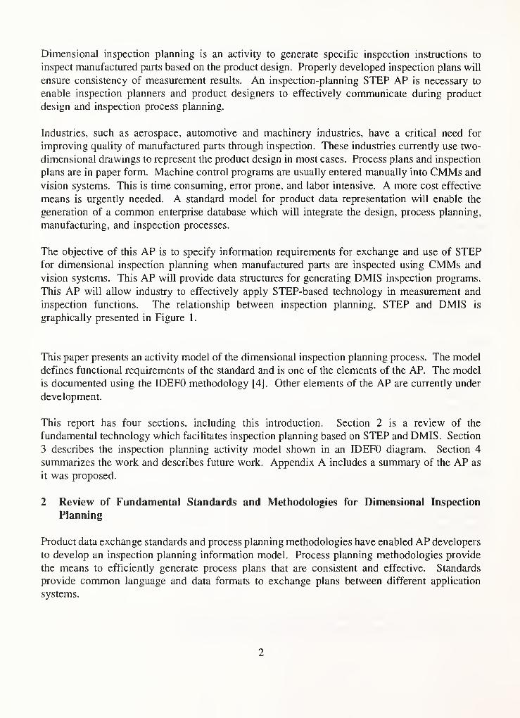
In Diagram A42, Activity A42 is further decomposed into three activities (A421 — A423) for
the detailed specification. Activity A421 determines the measurement position, e.g. points to
measure using touch-trigger probe or camera positions using video camera to inspect surface.
22

No matter what sensor is used, discrete points (samples) on part surfaces are taken from a
surface. These measured points are then used to evaluate the feature whether it is within
tolerance specification.
Activity A422 determines the inspection sequence. The considerations in this activity include
sequence of orientations in measurement, sequence of measuring tolerances in each orientation,
sequence of measuring features in each tolerance, sequence of measuring surfaces in each feature
and sequence of taking sample points on each surface. Also, the transitions of probe (or sensor)
from orientation to orientation, tolerance to tolerance, feature to feature, surface to surface, and
point to point are specified.
Activity A423 determines process parameters. The process parameters are values that influence
the inspection process, such as machine speed, ambient light, room temperature, machine mode,
sensor orientation, etc. The process parameters are set initially and reset as necessary in the
measurement sequence.
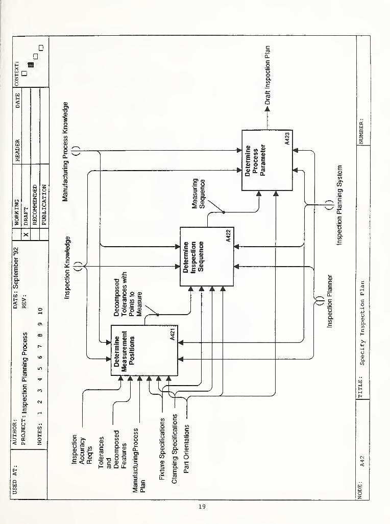
In Diagram A43, Activity A43 is further decomposed into two activities (A431 — A432) for the
detailed specification. Activity A431 generates machine-and-probe motion simulation. This
simulation is for verification purposes. The simulation determines whether the probe collides
with part, fixture or machine.
Activity A432 approves or disapproves the draft plan by an inspection plan validator based on
the draft plan and simulation. Change requests may be sent to the inspection planner by the plan
validator to modify and improve the draft plan. A draft plan is approved when this verification
process shows there are no collisions or interference with sensor operation.
4 Conclusion
The inspection process planning activity model described in this paper has been developed as part
of the ISO STEP standard. The purpose of this activity model is to capture information required
in the dimensional inspection planning process based on STEP and DMIS. The activity model
was specifically developed for coordinate measuring using tactile probes and video sensors which
are commonly used in industry. The IDEFO diagram is a model which specifies activities of
inspection planning that use and access the design data retrieved from a STEP database. The
planning activities produce an inspection plan which can be exchanged among different
inspection planning systems, CAD systems or CIM systems.
The next phase in the development of an inspection planning AP will be to generate a data model
to characterize the structure of the information identified in the activity model. Work is nowunder way to develop an IDEE lx [6] data model based on the activity model presented in this
paper.
23

Acknowledgement
The author gratefully acknowledges encouragements and many technical suggestions from Dr.
Theodore H. Hopp and Ms. Jeane Ford. Thanks also extend to Dr. Yin-Lin Shen and Mr.
Michael Read for their assistance in preparation of the activity model. Without their help, it
would not have been possible to complete this report.
24

5
References
1 ISO 10303 "Product Data Representation and Exchange", Part 1 "Overview and Fundamental
Principles", Draft International Standard, 1993. National Computer Graphics Association,
2722 Merrillee Drive, Suite 200, Fairfax, VA 22031.
2 ISO TC184/SC4AVG4 N66, Palmer, M., editor, "Guideline for the Development and
Approval of STEP Application Protocols", version 1.1, February 20, 1992. National
Computer Graphics Association, 2722 Merrillee Drive, Suite 200, Fairfax, VA 22031.
3 ANSI/CAM-I Dimensional Measuring Interface Standard (DMIS), version 2.1, 1990.
Computer Aided Manufacturing - International, Inc., 1250 E. Copeland Rd., Suite 500,
Arlington, Texas 76011.
4 Integrated Computer-Aided Manufacturing (ICAM) Architecture Part II, Volume IV -
Functional Modeling Manual (IDEFO), Material Laboratory, U.S. Air Force Wright
Aeronautical Laboratories, June 1981.
5 ISO 10303 "Product Data Representation and Exchange", Part 11 "EXPRESS Language
Reference Manual", Draft International Standard, 1993. National Computer Graphics
Association, 2722 Merrillee Drive, Suite 200, Fairfax, VA 22031.
6 Integrated Computer-Aided Manufacturing (ICAM) Architecture Part II, Volume V -
Informational Modeling Manual (IDEFl), Material Laboratory, U.S. Air Force Wright
Aeronautical Laboratories, June 1981.
7 Ham, I. and Lu, S., "Computer-aided Process Planning: The Present and the Future", Annals
of the CIRP, Vol. 37/2, 1988.
8 Alting, L. and Zhang, H., "Computer Aided Process Planning: the state-of-the-art survey".
International Journal of Production Research, Vol. 27, No. 4, 1989, pp. 553-585.
9 Chang, T. and Wysk, R., An Introduction to Automated Process Planning Systems, Prentice-
HaU, 1985.
10 Hopp, T.H. and Lau, K. C., "A Hierarchical Model-Based Control System for Inspection",
Annals of the CIRP, Vol. 33/1, 1984.
1 1 ElMaraghy, H. A. and Gu, P. H., "Expert System for Inspection Planning", Annals of the
CIRP Vol. 36/1, 1987.
12 Menq, C.-H., Wang, C.-L., and Yau, H.-T., "An Intelligent Planning Environment for
Automated Dimensional Inspection of Manufacturing Objects", Symposium on Concurrent
Product and Process Design, ASME 1989 Winter Meeting.
25

13 Brown, C. W. and Gyorog, D. A., "Generative Inspection Process Planner for Integrated
Production", Symposium on Concurrent Product and Process Design, ASME 1990 Winter
Meeting.
14 Groabowske, H., Andrei, R, Geiger, K. and Schmitt, M. "Vision based on-line inspection of
manufacturing parts" in Human Aspects In Computer Integrated Manufacturing, G.J. Oiling
and F. Kimura (editors), Elsevier Science Publishers B.V. (North Holland), Proceedings of
IFIP, 1992.
15 ANSI B4.4M, "Inspection of Workpieces", 1981, Published by ASME, New York.
16 ANSI/ASME, PTC 19.1 - 1985, "Measurement Uncertainty", Published by ASME, NewYork.
26

APPENDIX A STEP Candidate Application Protocol Summary
1. AP Title: Dimensional Inspection Process Planning for Coordinate Measuring Using
Tactile and Video Sensors
2. Date of Submission: August 14, 1992
3. Nominators: Jesse Crusey Greg A. Paul William D. Cain
WG3/T3 Leader WG3/ri 1 Leader WG3^ Leader
4. Proposal Advocate: Shaw C. Feng
Mailing Address: NISTMetrology A 127
Gaithersburg, MD 20899
U. S. A.
Telephone: +1 301 975-3551
Facsimile: +\ 301 258-9749
E-Mail: feng(5)cme.nist.gov
5. Scope: This Application Protocol (AP) specifies information requirements for exchange,
access, and use of STEP for dimensional inspection of manufactured parts using
coordinate measuring systems such as coordinate measuring machines (CMMs) and
vision systems. This AP will provide specific data structures for generating DMISinspection programs.
This AP will apply rules, constraints, and definitions of the measurement planning
specified by U.S. ANSI B89.3.2 which is being developed and related ISO and DINstandards.
This AP is a component of Manufacturing Process Planning Application Protocol.
This AP will directly support the in-process inspection requirements of the NCProcess Plan AP (currently under development).
The primary use of the AP will be part dimensional inspection and the archiving of
inspection result data.
The following are considered out of scope for this AP:- Inspection strategy generation,
- Open set-up inspection, and
- Part measurement using gages and manual measuring devices.
27

6. Application Activity Model (AAM):
A working draft has been developed.
7. Evidence of Industry Need for the AP;
The aerospace, automotive, and machinery industries, to name a few, have a critical need for
improving methods for piece part inspection. These industries currently use, in most cases,
drawings (two-dimensional), process plans, and inspection plans, in paper form, to manually
program or enter relevant data to CMMs and vision machines for inspecting discrete piece
parts. This is time consuming, error prone, and labor intensive. A more cost effective means
is urgently needed.
8. Summary of industry review of the scope and functional requirements:
In progress. A survey form has been developed.
9. Overlap and relationships to other APs or AP projects:
This AP will use AP for Boundary Representation and AP for Surface Representation to
access part topology and surface data. This AP will interact with the Manufacturing Process
Planning project which includes a suite of APs.
10. Status of required resource models:
The following resource models are required for this AP:
STEP first release
PART 41
PART 42
PART 43
Models to be integrated
Process Plan (no assigned part number)
PART 47 Shape Tolerance
PART 48 Form Feature
Surface Information (no part number)
Inspection (no part number or owner)
28

1 1. Current participants and committed resources for developing the AP:
The ESPRIT VIMP project and the NIST National PDES Testbed project have offered to
support development of the AP. NIST provides two full-time-equivalents and ESPRIT VIMPprovides a quarter of a full-time-equivalent to develop this AP.
Chairs and members of Project 3, 7, and 1 1 within WG 3 have indicated a desire to support
this AP development. We will also work closely with the U.S. ANSI DMIS and B89.3.2
standard committees for applying their expertise as input to this development.
12. Schedule for delivering AP with existing resources:
A draft approved for technical content could be completed within three years of formal
starting. The review, outside the STEP committee, will take about one year. The schedule
for balloting as a CD will depend on the STEP qualification and integration process.
29

»'’’' "-f '•.iiii., lAiiteifeP
IM .Jtr ':hr U>m '!i:'^nli UiA om
',' '
"
;: ^
' '
•* ;v(^,
K' -*^«•r'»^ - :.- r'
-7 .,".' ;t?s(^. fr v
, -•; sW.-o,-,, . r.'^. ' .'
, \ '
,
:; ,;„.: "".inr"' ' ^l^„.
:
//V"'- ''‘“
;, .i -t.":. '.^i,.•/i’
'
, ,'7''^^'^''
jn';':"'
iS '
,
'•% 1'"’
j,> (,4
?, ,v;^'
=(t’
^i.,' Ill VyV f*‘ii K:
^*'’5 : '(''Vis'll..'
.Vi;.
5?. : M
'i : i
. h'' . » V
;
• ''111,';!*^:i'^";
;
,
;: 4 fi *'}j^' I’
''*v.:u«».t.,
PM
l1 <
... ^
'
. v .-iS'i!','"n
vp : I , I'," ^:t
: )
'
‘' Sh -((': -«!'
'"liifr ::'
;<« Jr’-.i':',' V «i;‘<»: ('.'‘lu,,-: ,i<!(i^'
,‘i ;. .\(y> -^f-'w
'.if-
j^L'
mm‘''iMi
wiSiii!
;i, "i Mi
M-
ri
'*fy ii^.BalffS:
'.Bi:
-M-
m

