dimensions of coupling in middleware
TRANSCRIPT
Dimensions of Coupling in Middleware
Lachlan Aldred1, Wil M.P. van der Aalst1,2, Marlon Dumas1, and Arthur H.M. ter Hofstede1
1 Faculty of IT, Queensland University of Technology, Australia2 Department of Mathematics and Computer Science, Eindhoven University of Technology, The Netherlands
Abstract. It is well accepted that different types of distributed architectures require different degrees ofcoupling. For example, in client-server and three-tier architectures, application components are generallytightly coupled, both with one-another and with the underlying middleware. Meanwhile, in off-line trans-action processing, grid computing and mobile applications, the degree of coupling between applicationcomponents and with the underlying middleware needs to be minimised. Terms such as “synchronous”,“asynchronous”, “blocking”, “non-blocking”, “directed”, and “non-directed” are often used to refer tothe degree of coupling required by an architecture or provided by a middleware. However, these termsare used with various connotations. And while various informal definitions have been provided, there isa lack of an overarching formal framework to unambiguously communicate architectural requirementswith respect to (de-)coupling. This article addresses this gap by: (i) formally defining three dimensionsof (de-)coupling; (ii) relating these dimensions to existing middleware; and (iii) proposing notational el-ements to represent various coupling integration patterns. This article also discusses a prototype thatdemonstrates the feasibility of its implementation.
Keywords: Distributed architecture, Coupling, Decoupling, Asynchronous/synchronous communica-tion, Message-Oriented Middleware
1 Introduction
Modern approaches to integrating distributed systems almost invariably rely on middleware.These middleware take many forms, ranging from distributed object brokers, to message-oriented middleware and enterprise service buses. Each family of middleware is designed toprovide proven solutions to a certain set of distributed system integration issues, but how canone compare their relative strengths and weaknesses when they are so different at the core?Indeed, a unified framework for middleware remains elusive.
The heterogeneity of contemporary middleware reflects the absence of a consensus on theright set of communication abstractions to integrate distributed applications [1]. This lack ofconsensus can be observed even for the most elementary communication primitives, namelysend and receive. For example in sending a message, the semantics of what happens (a) if itdoesn’t arrive, or (b) if it gets buffered (and if so if this happens locally/remotely); is usu-ally not clear until the choice a technology has been made. As noted by Cypher & Leu: “theinteractions between the different properties of the send and receive primitives can be ex-tremely complex, and ... the precise semantics of these primitives are not well understood” [2].Coupling, or the way in which endpoints are connected, lies at the heart of this issue.
The style of coupling can vary from one family of middleware to another. For instancesolutions inspired by CORBA [3] use the Remote Procedure Call (RPC) paradigm, whereinthe sender and receiver applications typically become synchronised at the thread level. Con-versely Message-Oriented Middleware (MOM) solutions use what is usually referred to as anasynchronous approach. In spite of these differences there are MOM implementations sup-porting request-response, e.g. Java Message Service (JMS) [4], and there are RPC solutionssupporting asynchronous interactions. While this sounds encouraging it doesn’t mean thatthese solutions are interchangeable at the conceptual level. Consequently, conceptual com-parisons become mired in technical detail. It is one of the goals of this paper to decoupleconceptual comparisons from technical ones - at least when it comes to inter-coupling.
A full analysis of middleware would be a daunting task. The set of features is large, par-ticularly when one considers, for example privacy, non-repudiation, transactions, time-outs,and reliability. This article focuses on the notion of (de-) coupling, as it is the source of manydistinctions central to the design of distributed applications. Specifically, the article formulatesa framework for characterising levels of coupling. The main contributions of the article are:
– A detailed analysis of the notion of decoupling in middleware and a formal semantics ofdimensions of coupling in terms of Coloured Petri Nets (CPNs) [5].
– A collection of notational elements for integration modelling based on the notions of cou-pling previously identified. These notational elements are given a visual syntax extendingthat of Message Sequence Charts (MSCs) [6].
– A classification of middleware in terms of their support for various forms of (de-)coupling.This classification can be used as an instrument to assist in middleware selection, al-though requirements outside the scope of this study may play an equally important rolein middleware selection (e.g. transaction support, non-repudiation and message filteringcapabilities).
– A prototype demonstrating the possibility of supporting all styles of coupling in a consistentand uniform way.
The article is structured as follows. Section 2 establishes a nomenclature. Section 3 for-malises a set of coupling dimensions while Section 4 shows how these dimensions can becomposed, leading to a set of uni-directional coupling integration patterns that provide a ba-sis for integration modelling. Section 5 introduces bi-directional interactions and incorporatesthem into the same conceptual framework. Section 6 presents a framework for comparingmiddleware solutions based on the uni-directional, and bi-directional patterns. Section 7 in-troduces JCoupling : an open source prototype that combines all of the proposals of this article.Sections 8 and 9 present related work and conclusions respectively.
This article is an extension of our previous analysis of coupling for elementary interactions[7]. It extends [7] to incorporate publish-subscribe techniques into the models of interaction,and by encompassing compound interactions (e.g. request-response). We have introduced re-mote fault reporting, timeouts, aggregate messaging, and multicast - making the proposalsmore grounded. This article also introduces a new proof of concept prototype (JCoupling)that implements the theoretical models presented in this article and in [7].
2 Background
This section defines key terms related to coupling used in the rest of the paper.A message is a discrete unit of information (containing for example a command, data,
request, or an event) that is passed between endpoints. Depending on the technology it maycontain header metadata (e.g. message ID/ timestamp) and/or payload data.
An endpoint is a communicating entity and is able to perform interactions. It may havethe sole capability of sending/receiving messages and defer processing any information tosomething else, or it may be able to communicate and process.
An interaction refers to endpoints exchanging information [8]. The most basic interactionis a uni-directional message exchange (elementary interaction).
A channel is an abstraction of a message destination. This abstraction is similar tothe notion of “queue” supported by JMS, WebsphereMQ [9], and Microsoft Message Queue(MSMQ) [10]. A common attribute of common queues (channels) offered by WebsphereMQ
2

and MSMQ is that they are not necessarily private. For instance, these solutions permit manyendpoints to invoke a receive request over the same queue (channel) concurrently. In such acase the middleware treats these two endpoints as if they are in fact competing for a mes-sage [11].1 Channels can be extended with many functions. Examples include preservation ofmessage sequence [12, 2], authentication, and non-repudiation [11].
A private channel is slightly different to a channel in that in this case there is somethingpreventing more than one receiving endpoint from being able to compete for messages onthe same channel. A private queue (available from WebsphereMQ), is one example where themiddleware explicitly doesn’t allow certain channels to be shared. Conversely in cases thedesign or architecture of the middleware won’t allow shared channels by design; for exampleTPC Sockets don’t support many applications sharing the same IP-address/port combination.
A topic is another form of symbolic destination. Like channels many receivers may consumemessages off one topic – the difference being that all receivers get a copy of the message.
Eugster’s survey of Publish-Subscribe [12], introduced three dimensions of decoupling:
– Thread Decoupling – (referred to by Eugster as Synchronisation Decoupling) wherein thethread inside an endpoint does not have to wait (block) for another endpoint to be in the‘ready’ state before message exchange begins.
– Time Decoupling – wherein the sender and receiver of a message do not need to be involvedin the interaction at the same time.
– Space Decoupling – wherein the messages are directed to a particular symbolic address(channel) and not directly to the address of an endpoint.
The dimensions of decoupling have relevance to a large spectrum of middleware, includingMOM, space-based [13], and RPC-based middleware.
3 Decoupling Dimensions of an Interaction
This section is based on Eugster’s dimensions of coupling. In this section we present conceptualrepresentations and Coloured Petri nets (CPNs) of patterns for coupling distributed applica-tions. At this stage we focus on uni-directional interactions only. Bi-directional interactions(e.g. request-response) are presented in Section 5.
We chose CPNs to formalize the proposed notions of coupling. While we could have usedother models of concurrent systems, e.g. Process Algebra [14] or π-calculus [15], we preferredCPN due to its graphical nature, its mature (and freely available) tool support, and the factthat the concept of buffer, which is central in the formalisation, maps directly to the conceptof place in Petri nets.
All CPNs have been fully implemented and tested using CPN Tools [16].
3.1 The Thread-coupling Dimension
Thread-decoupling enables “non-blocking communication”, for either, or both, the sender andreceiver. Non-blocking communication allows the endpoint’s thread to interleave processingwith communication. In the following paragraphs we introduce some notational elements forvarious forms of thread decoupling as well as the CPN formalisation.
1 In such circumstances one endpoint will get the message and the other will typically be made to continue wait-ing/timeout.
3

Pattern 1: Blocking Send. A message send action can either be blocking or non-blocking.A blocking send implies that the sending application must yield its thread of control whilethe message is being transferred out of the local application. It does not matter if it is pass-ing the message over a wide area network connection or to another local application. If thesender’s thread, at least, blocks until the message has left the local application and its embed-ded middleware, it is blocking2. Figure 1(b) is a CPN of a blocking send. The outer dashedline represents the endpoint while the inner dashed line represents middleware code that isembedded in the endpoint. These do not form part of the CPN language and are used only toindicate architectural concerns.
(a) Notation blockingsend.
initiate
send
begin
x-port
finish
x-port
msg
ready
init'd
in
progrs
app
contrl Msg
Msg
Thread
Msg
msg1
t1
thr
thr
msg
msg
Endpoint Application
Embedded
Middleware
process
thr
msg
msg
msg
(b) CPN - blocking send.
Fig. 1. Blocking send. After initialising a send action, the transition “process” cannot fire until a thread is returned atthe end of message transmission.
For readers unfamiliar with CPNs, the next two paragraphs introduce the notation (also see[5]). In Figure 1(b) the circular nodes are called ‘places’ (e.g. “msg ready”, “app contrl”, and “inprogrs”), and they represent potential states. The rectangular nodes are called ‘transitions’(e.g. “initiate send”, “begin x-port”, and “process”), and change a CPN from one state toanother. Tokens, e.g. the black dots in the places “msg ready” and “app contrl”, represent aparticular state of the model. Figure 1(b) is in a state where a message is ready to be sent,and the application has control of its own thread. This is the initial state of the CPN, andis referred to as its ‘initial marking’. According to the firing rules of CPNs two transitions(“initiate send” and “process”) are concurrently enabled for the initial marking. When eitherof these transitions fire it will consume one token from each of its ‘input places’ and produceone token into each of its output places. A transition is enabled if every one of its inputplaces contains at least one token. For example, firing “initiate send”, will consume one tokenfrom each input place.3 Consequently the transition “process” becomes disabled because “appcontrl” now contains zero tokens. Transition “process” cannot become re-enabled until thetransition “finish x-port” returns a token to the place “app contrl”. “Finish x-port” onlyreturns this token once the message has left the sender. In Figure 1(b) the places are type-constrained. For instance the place “msg ready” can only hold tokens of type Msg – shownas an annotation to its bottom-right side. The annotations shown at the top-right side ofthe places “msg ready” and “app contrl” are references to constant values. The values areused to determine the initial marking of Figure 1(b). For instance the annotation “msg1” isa constant value of type Msg. Its presence puts a token into the place “msg ready”. Each arc
2 If the interaction was bi-directional it would block longer (Section 5).3 By contrast, firing “process” will remove the token from “app cntrl” and then place a token back in the input place
(because it has a bi-directional arrow).
4
entering/leaving a place in this CPN is annotated by a variable – typed according to the placethe arc connects to. Arcs leaving transitions specify the value of the token to be produced andmay use arbitrary ML [17] functions. This feature will be used in Section 3.3.
In Figure 1(b), when a message is ready (represented by a token inside the place “msg-ready”) and the application is ready (represented by a token inside the place “app-contrl”)the endpoint gives the message to the embedded middleware.4 The endpoint yields its threadof control to the embedded middleware, getting control back once the message has completelyleft the embedded middleware. Inside the embedded middleware the transitions “begin-x-port”,“fin-x-port”, and the place “in-progress” are placed over the edge of the endpoint. This denotesthat the remote system (receiver endpoint or middleware service) will bind to the sender bysharing these transitions and the place. The assumption is that inside the middleware, at adeeper layer of abstraction, systems communicate in a time-coupled, thread-coupled manner,regardless of the behaviour exposed to the endpoint applications.5 Therefore this CPN maybe “transition bounded” with remote systems.6
In a blocking send there is a thread coupling of the sender application (endpoint) withsomething else – but not necessarily the receiver as we will show in Section 3.2.
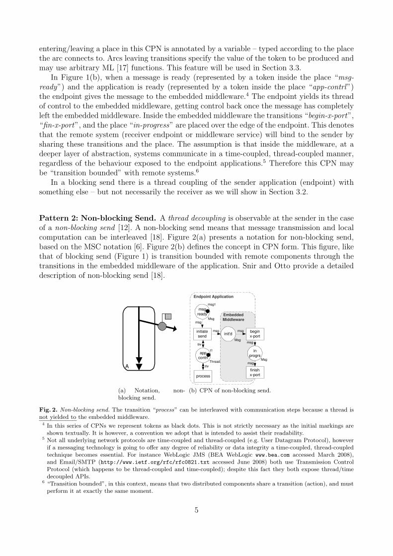
Pattern 2: Non-blocking Send. A thread decoupling is observable at the sender in the caseof a non-blocking send [12]. A non-blocking send means that message transmission and localcomputation can be interleaved [18]. Figure 2(a) presents a notation for non-blocking send,based on the MSC notation [6]. Figure 2(b) defines the concept in CPN form. This figure, likethat of blocking send (Figure 1) is transition bounded with remote components through thetransitions in the embedded middleware of the application. Snir and Otto provide a detaileddescription of non-blocking send [18].
A
(a) Notation, non-blocking send.
Embedded
Middleware
initiate
send
begin
x-port
finish
x-port
msg
ready
init'd
in
progrs app
contrl Msg
Msg
Thread
Msg
msg1
t1
msg thr
msg
msg msg
msg
Endpoint Application
process
thr
(b) CPN of non-blocking send.
Fig. 2. Non-blocking send. The transition “process” can be interleaved with communication steps because a thread isnot yielded to the embedded middleware.4 In this series of CPNs we represent tokens as black dots. This is not strictly necessary as the initial markings are
shown textually. It is however, a convention we adopt that is intended to assist their readability.5 Not all underlying network protocols are time-coupled and thread-coupled (e.g. User Datagram Protocol), however
if a messaging technology is going to offer any degree of reliability or data integrity a time-coupled, thread-coupledtechnique becomes essential. For instance WebLogic JMS (BEA WebLogic www.bea.com accessed March 2008),and Email/SMTP (http://www.ietf.org/rfc/rfc0821.txt accessed June 2008) both use Transmission ControlProtocol (which happens to be thread-coupled and time-coupled); despite this fact they both expose thread/timedecoupled APIs.
6 “Transition bounded”, in this context, means that two distributed components share a transition (action), and mustperform it at exactly the same moment.
5
A non-blocking send is a necessary condition, but not a sufficient condition to achievetotal thread decoupling, which is to say that the receive action must also be non-blocking.Rephrased, if both the send and receive are blocking (non-blocking) then a total thread cou-pling (decoupling) occurs. A partial thread decoupling occurs when the send is blocking andthe receive non-blocking, or vice-versa.
The non-blocking send is fairly uncommon for middleware solutions. For instance all RPC-based implementations use blocking send. MOM implementations such as “Websphere MQ”[9] and MSMQ partially support it; but only if the middleware service was deployed onto thelocal host, the send operation only blocks while the message is passed between applicationson the same machine.
Pattern 3: Blocking Receive. Like message send, message receipt can either be blockingor non-blocking [2]. The definition of blocking receive is that the application must put athread into a waiting state in order to receive the message (ownership of the thread is usuallyreturned to the endpoint when the message is received). This means that the receiver thread iscoupled to either the message sender directly or to some form of queue on a middleware service(depending on whether the middleware queues messages between the sender and receiver, ornot). Section 3.2 formalises this notion. Figure 3 presents a notation and model for blockingreceive. When the transition “initiate receive” of Figure 3(b) is fired, the token sitting in place“thread” is consumed, and a token is put into place “rcv ready”. Consequently, the transition“process” is no longer enabled. Meaning that the model cannot progress until a messagearrives (i.e. the receiver is in the blocking state). This may occur before a correspondingsender endpoint sends its message.
B
(a) Notation, blockingreceive.
Embedded
Middleware
rcv
ready
initiate
receive
begin
x-port
finish
x-port msg
in
in
progrs
thread
Msg
Thread
Msg
msg
msg
thr
thr
msg
thr
t1
thr
Endpoint Application
process
thr
Thread
msg
req
Request r1
r
(b) CPN of blocking receive.
Fig. 3. Blocking receive. A thread must be yielded to the embedded middleware until the message has arrived.
Pattern 4: Non-blocking Receive. The non-blocking receive occurs when the applicationcan receive a message, without forcing the current thread to wait. This is illustrated in Figure 4.
A well-known embodiment of non-blocking-receive is the event-based handler described inJMS [4]. Once a handler is registered with the middleware it is called-back when a messagearrives. The Message Passing Interface (MPI) provides another embodiment of non-blockingreceive that is not event-based [18], wherein the receiver polls for the presence of a new message.
Non-blocking receive, as a communication abstraction, seems less popular than blockingreceive. This is probably because blocking receive interactions are simpler to program anddebug [11]. One frequently observes statements about the merits of an asynchronous archi-tecture. While such statements are indeed valid, they usually refer to the merits of queuing
6

B
(a) Notation, non-blocking receive.
Embedded
Middleware
rcv
ready
initiate
receive
begin
x-port
finish
x-port msg
in
in
progrs
thread
Msg
Thread
Msg
msg
msg
thr
msg
thr
t1
thr
Endpoint Application
process Thread
thr
msg
req
Request r1
r
(b) CPN of non-blocking re-ceive.
Fig. 4. Non-blocking receive. A thread need not be yielded to the middleware in order to receive.
messages between the sender and the receiver, and have little to do with the fact that thethreads of control are blocked or not. Therefore the threading dimension as presented in thissection is orthogonal to the general usage of the word “asynchronous”.
3.2 Time
The dimension of time decoupling is crucial to understanding the difference between manypeer-to-peer middleware paradigms and server-oriented paradigms (e.g. MPI versus MOM).In any elementary interaction time is either coupled or decoupled.
Pattern 5: Time-Coupled. Time-coupled interactions, like those typically found in MPI,cannot take place unless both endpoints are concurrently connected. There is no possibilityof queueing messages between the two endpoints. In time-coupled arrangements the interac-tion begins with the message being wholly contained at the sender endpoint. The transition-boundedness of endpoints can guarantee that the moment the sender begins sending the mes-sage, the receiver begins receiving. This concept is presented in Figure 5 wherein the endpointapplications are joined directly at the bounding transitions (“begin x-port” and “finish x-port”).Time-coupled interactions accord with the general usage of the word “synchronous”. Figure 5does not show the endpoints. The “sends” and “receives” may be blocking or non-blocking.Hence, Figure 5 should be seen in conjunction with the earlier figures.
A B
Tim
e
(a) Notation, time coupled.
begin
x-port
finish
x-port
in
progrs
msg
msg
Embedded
Middleware
Embedded
Middleware
msg
msg Msg
Endpoint Application Endpoint Application
(b) CPN of time coupled messaging.
Fig. 5. Time coupling is characterised by transition-bounded systems.
7

Pattern 6: Time-Decoupled. Time-decoupled interactions allow messages to be exchangedirrespective of whether or not each endpoint is concurrently operational. In this case messagesare queued between the sender and the receiver. To achieve time decoupling a third endpoint isneeded, that both the sender and receiver can access. Time-decoupling is presented in Figure 6.The two endpoints, and the middleware service are again transition-bounded. However now,the middleware service is able to buffer the message, as captured by the place “buffr’d”.
The place “buffr’d” is filled with a token when the sender has finished sending a message,and the receiver has not started receiving that message. One token in the place “buffr’d” rep-resents one message being held on a middleware that sits between the sender endpoint and thereceiver endpoint. In Figure 6 the proceeding transition will fire immediately because, in thisCPN the presence of a token in “buffr’d” enables it. Like in WebLogic’s JMS implementationthere is (conceptually) no limitation on the number of messages that can be buffered.
A B
Tim
e
(a) Notation, time decoupled.
begin x-port
finish
x-port
in
progrs
msg
msg
Embedded
Middleware Embedded
Middleware
msg
msg
Msg
Middleware Service Endpoint Application Endpoint Application
begin x-port
finish
x-port
in
progrs
msg
msg
Msg
buffr'd
msg
msg
Msg
(b) CPN of time decoupled messaging.
Fig. 6. Time decoupling is characterised by the presence of an intermediate endpoint.
MOM solutions such as Websphere MQ and MSMQ are typically deployed in a “huband spoke” arrangement, which is truly time-decoupled. An alternative arrangement is the“peer-to-peer” topology. In such a topology the sender endpoint and middleware service aredeployed on the same host. This latter topology may seem time-decoupled, but it is not becauseinteractions can only take place if both hosts are concurrently connected to the network. Thismay be a problem for endpoints on hosts on unreliable networks, e.g. mobile devices.
3.3 Space
Space is the final dimension of decoupling. By “space” we refer a dimension of coupling thattakes into account the degree to which sender endpoint can control which instance receives themessage. If the sender can totally control which endpoint instance would receive the messagewe can assume a high degree of space coupling, and vice versa.
Pattern 7: Space Coupled. A space coupled interaction has the property that only onereceiver can possibly receive the message. This behaviour could be driven by, for example,hard location data (e.g. an IP-Address/port combination), or more abstract mechanisms in-corporated into a middleware (e.g. private queues in IBM Websphere MQ). Figure 7 presentsthe concept of space coupling. The CPN for space coupling is presented at the end of thissection.
8

A B
Fig. 7. Notation, space coupled. The sender directly addresses the receiver.
Pattern 8: Space Decoupled (Channel) and Pattern 9: Space Decoupled (Topic).Space decoupled interactions on the other hand allow a sender to send a message withoutrequiring explicit knowledge of the receiver’s address. Decoupling in space generally makesarchitectures more flexible, and extensible.
A B
(a) Channel - one receiver gets themessage.
A B
(b) Topic - all receivers get the mes-sage.
Fig. 8. Extensions to MSCs representing two forms of space decoupling.
There are two distinct forms of space-decoupling. Space-decoupled architectures permitone sender to interact with one of many receivers (over a channel) or many of many receivers(over a topic), without uniquely identifying the receiver. Figure 8 introduces extensions toMSCs that present notations for “channel” and “topic” based interactions.
begin
x-port
finish
x-port
in
progrs
Embedded
Middleware
Middleware
ApidMsg
Endpoint Application Endpoint Application
(apID,msg)
(apID,msg)
init'd
sub-
scribe subscr-
iptions
new
subscr
DestMsg
SubscrSet
[]
ApidDest
[(9,top7),
(10,top7),
(1,adr1)]
(apID,dest)
[isTopic(dest) orelse
(isAddr(dest) andalso
not(eltS(dest, subs)))]
subs
(apID,dest)::subs
rcv
ready ApidDest
msg
in ApidMsg
Allocate
Fig. 9. CPN presenting a semantics for the space dimension. The transition “begin x-port” has been annotated with abox labelled “Allocate”, which means that this transition decomposes to a sub-net (see Figure 10).
In Figure 9, the transition “begin x-port” decomposes to the sub-net shown in Figure 10.7
The sub-net models the behaviour of the three options of the space dimension illustrated byfigures 7, 8(a), and 8(b). The places “new subscr”, “subscriptions” and transition “subscribe”
7 Sub-nets can be used to hide details. Specifically, a transition can be decomposed into a sub-net and by replacingthis “substitution transition” by its decomposition one obtains its semantics.
9

model the ability for receiver endpoints to subscribe to destinations. Each receiver has itsown unique application ID (type Apid). Hence a new subscription token (i.e. “apID, dest”)is an endpoint/application ID combined with the relevant destination. Transition “subscribe”takes this token and appends it to the list of subscriptions represented by the token in place“subscriptions”. This is performed in the following ML expression (apID, dest)::subs. Thedouble colon :: (an append operation) adds the data element (apID,dest) to the head of thelist subs.
There are three I/O places (“init’d”, “rcv ready”, and “in progrs” etc.) common to parentand sub-net. These places can also be found in the CPNs of the Thread-coupling, and Time-coupling dimensions. By linking with these I/O places a sender can expect interaction to occuraccording to one of the three patterns of space-coupling – depending on the type of the desti-nation. The sender pushes a token into the place “init’d” (which is typed DestMsg). Likewise,a receiver, linking to this model can push a token into the place “rcv ready”. This place istyped ApidDest and it identifies this receiver’s application and the channel, or destination,over which the message is to be received.
� � � � � � � �� � � �
� � �� � �
� � � � � � � � � �
� � � � � � � � � � � � � � � � � � �
� � � � � � � � � �
� � � � � � � � �
� � � � � � � � � � � � � � � � � � � �� � � � � � � �
� � � � � � � � �
� � � � � � � � �� � � � �
� � �� � � �
� � � � � � � � � � � � � � � �� � � � � � � � � � � � � �
� � � �� � �
� � � � � � � � � � �� � � �
� � � �� � � � � � �
� � � � � �
� � � �� � � �
� � � � � � � �
� � �� � � � �
� � � � � � � �
� � � � � � ! � " � � � �
� � � � � �
# � � � $ � �
� � �� �
� � � � $ � �
� �
# �
� �
� � � � � % � � � �
� & #� & #
� � � � � � � � � �
� � � � � � � � � �
� � � � � �� � � � � � � �
� � � � � � � � � � � � � � �� � � � � � � �
� � � � � $ � � � � � � � � �� � � � � � � � � �
Fig. 10. This CPN is the ‘Allocate’ sub-net refining transition “begin x-port” in Figure 9.
Figure 10 presents the sub-net decomposition of the transition “begin x-port” (from Fig-ure 9). This CPN shows how a unified underlying model could perform any of the three optionswithin the space dimension (i.e. topic, address, or channel). From this we can conclude thatit is possible to offer a clean implementation to all three forms of space (de-)coupling withinthe one middleware solution.
The input places (“init’d” and “rcv ready”), the output place (“in progrs”), and the in-put/output place (“subscriptions”) correspond to the similarly labelled places of the parentnet (Figure 9). Note that a subscription is essentially a combination of a reference to a desti-nation (of type topic) and a backward reference to the subscribing application. Similarly, anaddress essentially consists of a destination reference (of type address) being bound to onelistening application. This similarity explains the fact that transition “begin addr” shares theinput place “subscriptions” with transition “begin topic”.8
8 Shown in Figure 9, is the transition for adding a new subscription to either an address or a topic. In this a transitionguard prevents more than one application binding to an address at any time, while allowing many applications tosubscribe to the same topic.
10
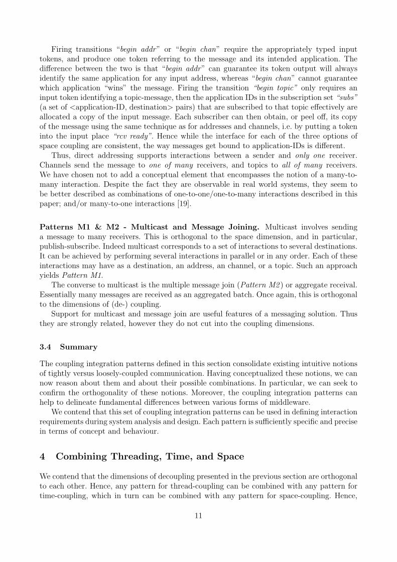
Firing transitions “begin addr” or “begin chan” require the appropriately typed inputtokens, and produce one token referring to the message and its intended application. Thedifference between the two is that “begin addr” can guarantee its token output will alwaysidentify the same application for any input address, whereas “begin chan” cannot guaranteewhich application “wins” the message. Firing the transition “begin topic” only requires aninput token identifying a topic-message, then the application IDs in the subscription set “subs”(a set of <application-ID, destination> pairs) that are subscribed to that topic effectively areallocated a copy of the input message. Each subscriber can then obtain, or peel off, its copyof the message using the same technique as for addresses and channels, i.e. by putting a tokeninto the input place “rcv ready”. Hence while the interface for each of the three options ofspace coupling are consistent, the way messages get bound to application-IDs is different.
Thus, direct addressing supports interactions between a sender and only one receiver.Channels send the message to one of many receivers, and topics to all of many receivers.We have chosen not to add a conceptual element that encompasses the notion of a many-to-many interaction. Despite the fact they are observable in real world systems, they seem tobe better described as combinations of one-to-one/one-to-many interactions described in thispaper; and/or many-to-one interactions [19].
Patterns M1 & M2 - Multicast and Message Joining. Multicast involves sendinga message to many receivers. This is orthogonal to the space dimension, and in particular,publish-subscribe. Indeed multicast corresponds to a set of interactions to several destinations.It can be achieved by performing several interactions in parallel or in any order. Each of theseinteractions may have as a destination, an address, an channel, or a topic. Such an approachyields Pattern M1.
The converse to multicast is the multiple message join (Pattern M2 ) or aggregate receival.Essentially many messages are received as an aggregated batch. Once again, this is orthogonalto the dimensions of (de-) coupling.
Support for multicast and message join are useful features of a messaging solution. Thusthey are strongly related, however they do not cut into the coupling dimensions.
3.4 Summary
The coupling integration patterns defined in this section consolidate existing intuitive notionsof tightly versus loosely-coupled communication. Having conceptualized these notions, we cannow reason about them and about their possible combinations. In particular, we can seek toconfirm the orthogonality of these notions. Moreover, the coupling integration patterns canhelp to delineate fundamental differences between various forms of middleware.
We contend that this set of coupling integration patterns can be used in defining interactionrequirements during system analysis and design. Each pattern is sufficiently specific and precisein terms of concept and behaviour.
4 Combining Threading, Time, and Space
We contend that the dimensions of decoupling presented in the previous section are orthogonalto each other. Hence, any pattern for thread-coupling can be combined with any pattern fortime-coupling, which in turn can be combined with any pattern for space-coupling. Hence,
11
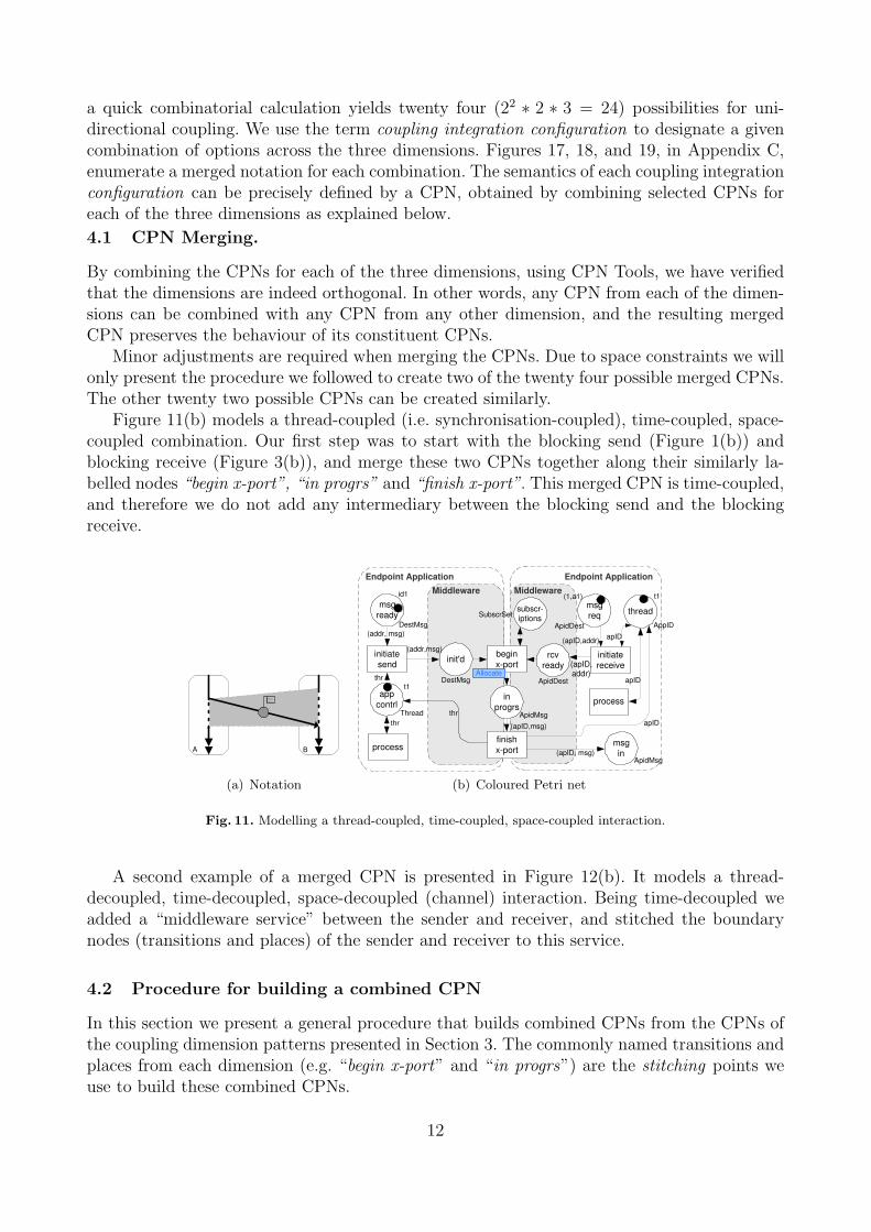
a quick combinatorial calculation yields twenty four (22 ∗ 2 ∗ 3 = 24) possibilities for uni-directional coupling. We use the term coupling integration configuration to designate a givencombination of options across the three dimensions. Figures 17, 18, and 19, in Appendix C,enumerate a merged notation for each combination. The semantics of each coupling integrationconfiguration can be precisely defined by a CPN, obtained by combining selected CPNs foreach of the three dimensions as explained below.
4.1 CPN Merging.
By combining the CPNs for each of the three dimensions, using CPN Tools, we have verifiedthat the dimensions are indeed orthogonal. In other words, any CPN from each of the dimen-sions can be combined with any CPN from any other dimension, and the resulting mergedCPN preserves the behaviour of its constituent CPNs.
Minor adjustments are required when merging the CPNs. Due to space constraints we willonly present the procedure we followed to create two of the twenty four possible merged CPNs.The other twenty two possible CPNs can be created similarly.
Figure 11(b) models a thread-coupled (i.e. synchronisation-coupled), time-coupled, space-coupled combination. Our first step was to start with the blocking send (Figure 1(b)) andblocking receive (Figure 3(b)), and merge these two CPNs together along their similarly la-belled nodes “begin x-port”, “in progrs” and “finish x-port”. This merged CPN is time-coupled,and therefore we do not add any intermediary between the blocking send and the blockingreceive.
A B
(a) Notation
initiate
send
msg
ready
init'd
DestMsg
DestMsg
id1
(addr,msg)
(addr, msg)
Endpoint Application
Middleware Middleware
rcv
ready
initiate
receive
msg
in
thread
ApidMsg
AppID
ApidMsg (apID, msg)
(apID, addr)
t1
Endpoint Application
begin
x-port
in
progrs
finish
x-port
(apID,msg)
app
contrl Thread
t1
thr
thr
process
thr
process
apID ApidDest Allocate
msg
req
apID
ApidDest
(apID,addr)
(1,a1)
apID
subscr-
iptions SubscrSet
(b) Coloured Petri net
Fig. 11. Modelling a thread-coupled, time-coupled, space-coupled interaction.
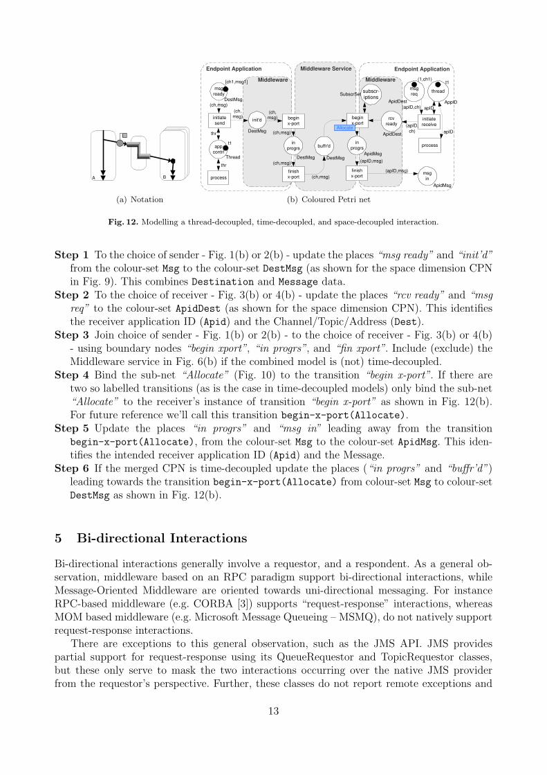
A second example of a merged CPN is presented in Figure 12(b). It models a thread-decoupled, time-decoupled, space-decoupled (channel) interaction. Being time-decoupled weadded a “middleware service” between the sender and receiver, and stitched the boundarynodes (transitions and places) of the sender and receiver to this service.
4.2 Procedure for building a combined CPN
In this section we present a general procedure that builds combined CPNs from the CPNs ofthe coupling dimension patterns presented in Section 3. The commonly named transitions andplaces from each dimension (e.g. “begin x-port” and “in progrs”) are the stitching points weuse to build these combined CPNs.
12
A B
(a) Notation
Middleware
initiate
send
msg
ready
init'd
DestMsg
DestMsg
[ch1,msg1]
(ch,
msg)
(ch,msg)
Endpoint Application
begin
x-port
finish
x-port
in
progrs
Middleware Service
buffr'd
DestMsg
Middleware
begin
x-port
finish
x-port
in
progrs
ApidMsg
(apID,
ch)
Endpoint Application
(ch,msg)
(ch,msg)
(apID,msg)
(apID,msg)
app
contrl Thread
t1
thr
process
thr
initiate
receive
msg
in
thread
AppID
ApidMsg
(apID,ch)
t1
process
apID ApidDest
DestMsg
Allocate
rcv
ready
msg
req
ApidDest
(1,ch1)
apID (ch,
msg)
(ch,msg)
subscr-
iptions SubscrSet
(b) Coloured Petri net
Fig. 12. Modelling a thread-decoupled, time-decoupled, and space-decoupled interaction.
Step 1 To the choice of sender - Fig. 1(b) or 2(b) - update the places “msg ready” and “init’d”from the colour-set Msg to the colour-set DestMsg (as shown for the space dimension CPNin Fig. 9). This combines Destination and Message data.
Step 2 To the choice of receiver - Fig. 3(b) or 4(b) - update the places “rcv ready” and “msgreq” to the colour-set ApidDest (as shown for the space dimension CPN). This identifiesthe receiver application ID (Apid) and the Channel/Topic/Address (Dest).
Step 3 Join choice of sender - Fig. 1(b) or 2(b) - to the choice of receiver - Fig. 3(b) or 4(b)- using boundary nodes “begin xport”, “in progrs”, and “fin xport”. Include (exclude) theMiddleware service in Fig. 6(b) if the combined model is (not) time-decoupled.
Step 4 Bind the sub-net “Allocate” (Fig. 10) to the transition “begin x-port”. If there aretwo so labelled transitions (as is the case in time-decoupled models) only bind the sub-net“Allocate” to the receiver’s instance of transition “begin x-port” as shown in Fig. 12(b).For future reference we’ll call this transition begin-x-port(Allocate).
Step 5 Update the places “in progrs” and “msg in” leading away from the transitionbegin-x-port(Allocate), from the colour-set Msg to the colour-set ApidMsg. This iden-tifies the intended receiver application ID (Apid) and the Message.
Step 6 If the merged CPN is time-decoupled update the places (“in progrs” and “buffr’d”)leading towards the transition begin-x-port(Allocate) from colour-set Msg to colour-setDestMsg as shown in Fig. 12(b).
5 Bi-directional Interactions
Bi-directional interactions generally involve a requestor, and a respondent. As a general ob-servation, middleware based on an RPC paradigm support bi-directional interactions, whileMessage-Oriented Middleware are oriented towards uni-directional messaging. For instanceRPC-based middleware (e.g. CORBA [3]) supports “request-response” interactions, whereasMOM based middleware (e.g. Microsoft Message Queueing – MSMQ), do not natively supportrequest-response interactions.
There are exceptions to this general observation, such as the JMS API. JMS providespartial support for request-response using its QueueRequestor and TopicRequestor classes,but these only serve to mask the two interactions occurring over the native JMS providerfrom the requestor’s perspective. Further, these classes do not report remote exceptions and
13

the TopicRequestor returns only the first response and ignores the responses of all othersubscribers.
The analysis of (de-) coupling has thus far only accounted for uni-directional interactions.Bi-directional interactions, the exchanging of data in two directions, occurs within the scopeof a single interaction for RPC style middleware. We challenge the notion that only thread-coupled systems allow bi-directional messaging within an interaction.
Bi-directional messaging, adds additional possibilities – for instance delivery receipt, andthe reporting of receiver-side faults. A delivery receipt (i.e. system acknowledgement) is anevent returned to the requestor, that its message has been successfully received. A deliveryreceipt (as distinguished from a response) does not imply that the targeted endpoint hasprocessed the message – just that it has received it. Finally a receiver side fault being prop-agated back to the requestor indicates that an error occurred during the processing of therequest message.
Likewise timeouts are also a relevant aspect to consider when modelling interactions. So farthey have not been presented even though we have modelled application-level faults. AppendixD presents a timed-CPN of Blocking-send, Blocking-receive showing how timeouts fit intothat particular pattern combination.9 Appendix D also summarises the results of simulationsconducted on these timed CPNs.
initiate
send
begin
x-port
finish
x-port
msg
ready
init'd
in
progrs app
contrl Id Msg
Msg
Thread
Msg
msg1
t1
thr
msg
msg
Endpoint Application
process
thr
msg
(id,msg)
(id,msg)
begin
respnse
finish
respnse
in
progrs IdResp
(id,res)
await
MsgID
id MsgID
id id+1
id
id
(id,res)
t1 result
(id,res)
IdResp
0 Middleware
(a) CPN of blocking send with re-sponse, or delivery receipt.
initiate send
begin x-port
finish
x-port
msg
ready
init'd
in
progrs app
contrl
Msg
Thread
Msg
msg1
t1
thr
msg
msg
Endpoint Application
process
thr
id MsgID
id id+1
Id Msg
(id,msg)
(id,msg)
begin
respnse
finish
respnse
in
progrs IdResp
(id,res)
(id,res)
msg
await
IdThread
result
IdResp
(id,res)
0
id
id
Middleware
(b) CPN of non-blocking sendwith response, or delivery receipt.
Fig. 13. Extended CPNs dealing with thread-coupling in bi-directional interactions from the requestor side. The changesmade to the related CPNs from Section 3 are black, while the unchanged elements are grey.
The CPN models from Section 3 covering threading and time were extended to optionallysupport request-response interactions, fault notification, and/or delivery receipt. These ex-tended CPNs (see figures 13 and 14) preserve the orthogonality of time, space, and threading.In Figure 13 the structure of the boundary nodes (“begin x-port”, “in progrs”, “finish x-port”,“begin respnse”, and “finish respnse”) in either CPN is identical. The major difference being
9 Note also that the prototype mentioned in Section 7 addresses timeouts and networking faults.
14
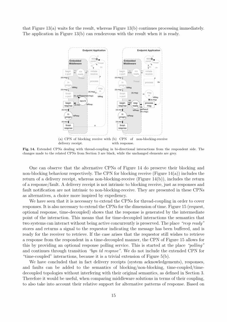
that Figure 13(a) waits for the result, whereas Figure 13(b) continues processing immediately.The application in Figure 13(b) can rendezvous with the result when it is ready.
rcv ready
initiate receive
begin x-port
finish
x-port
msg
in
in
progrs
app
contrl
IdMsg
Thread
IdMsg
(id,msg)
(id,msg)
thr
thr
t1
thr
Endpoint Application
process
thr
Thread
begin
respnse
finish
respnse
in
progrs IdResp
(id,res)
(id,res)
recv'd
(id,msg)
(id, getResponse(msg))
(id,res) IdResp
t1
Embedded
Middleware
(a) CPN of blocking receive withdelivery receipt.
rcv ready
initiate receive
begin x-port
finish
x-port
msg
in
in
progrs
app
contrl
IdMsg
Thread
IdMsg
(id,msg)
(id,msg)
thr
(id,msg)
thr
t1
thr
Endpoint Application
process
thr
Thread
begin
respnse
finish respnse
in
progrs IdResp
(id,res)
(id,res)
process
msg
resp
ready
(id,msg)
(id,
getResult
(thr,msg)) IdResp
(id,
res)
thr
Embedded
Middleware
(b) CPN of non-blocking-receivewith response.
Fig. 14. Extended CPNs dealing with thread-coupling in bi-directional interactions from the respondent side. Thechanges made to the related CPNs from Section 3 are black, while the unchanged elements are grey.
One can observe that the alternative CPNs of Figure 14 do preserve their blocking andnon-blocking behaviour respectively. The CPN for blocking receive (Figure 14(a)) includes thereturn of a delivery receipt, whereas non-blocking-receive (Figure 14(b)), includes the returnof a response/fault. A delivery receipt is not intrinsic to blocking receive, just as responses andfault notification are not intrinsic to non-blocking-receive. They are presented in these CPNsas alternatives, a choice more inspired by expediency.
We have seen that it is necessary to extend the CPNs for thread-coupling in order to coverresponses. It is also necessary to extend the CPNs for the dimension of time. Figure 15 (request,optional response, time-decoupled) shows that the response is generated by the intermediatepoint of the interaction. This means that for time-decoupled interactions the semantics thattwo systems can interact without being active concurrently is preserved. The place “resp ready”stores and returns a signal to the requestor indicating the message has been buffered, and isready for the receiver to retrieve. If the case arises that the requestor still wishes to retrievea response from the respondent in a time-decoupled manner, the CPN of Figure 15 allows forthis by providing an optional response polling service. This is started at the place “polling”and continues through transition “bgn td respnse”. We do not include the extended CPN for“time-coupled” interactions, because it is a trivial extension of Figure 5(b).
We have concluded that in fact delivery receipts (system acknowledgements), responses,and faults can be added to the semantics of blocking/non-blocking, time-coupled/time-decoupled topologies without interfering with their original semantics, as defined in Section 3.Therefore it would be useful, when comparing middleware solutions in terms of their coupling,to also take into account their relative support for alternative patterns of response. Based on
15

Endpoint Application Endpoint Application
begin
x-port
finish
x-port
in
progrs
msg
(id,msg)
IdMsg
Middleware Service
begin
x-port
finish
x-port
in
progrs buffr'd
begin
respnse
finish
respnse
in
progrs IdResp
begin
respnse
finish
respnse
in
progrs IdResp
resp
ready
bgn td
respnse
fin td
respnse
in
progrs
(id,res)
id
id id+1
0
IdMsg IdMsg (id,msg)
(id,msg)
(id, msg)
(id,msg)
(id,msg)
(id,msg)
polling
MsgId
ready
IdResp id
(id,res)
(id,res)
(id,res)
(id,res) (id,res)
(id,res) (id,res)
recv'd
IdResp
IdResp
(id,'Bufrd')
Middleware Embedded
Middleware
Fig. 15. Time decoupling CPN, extended to cover request-response interactions.
our survey of middleware solutions/standards, and theoretical modelling, we have arrived atthese patterns of request-response:
Pattern R1: Preprocess acknowledgement a signal, provided by the middleware, is re-turned to the requestor indicating the successful receipt of the message.
Pattern R2: Postprocess acknowledgement a signal, provided by the middleware, getsreturned to the requestor indicating that the message was successfully processed.
Pattern R3: Postprocess response a response, containing information provided by therespondent, gets returned to the requestor.
Pattern R4: Postprocess fault an exception/fault occurs in the respondent while process-ing the message, and information about this gets propagated back to the requestor.
Pattern R5: Receive response: blocking the requestor blocks for the response.Pattern R6: Receive response: non-blocking the requestor thread uses a non blocking
technique to receive the response.
The options for responding to a message do not interfere with the semantics of couplingand decoupling. For example, time-decoupling enables, but does not force “fire and forget”interactions. Likewise, a blocking-send does not imply a response, and a non-blocking senddoes not imply the lack of one.
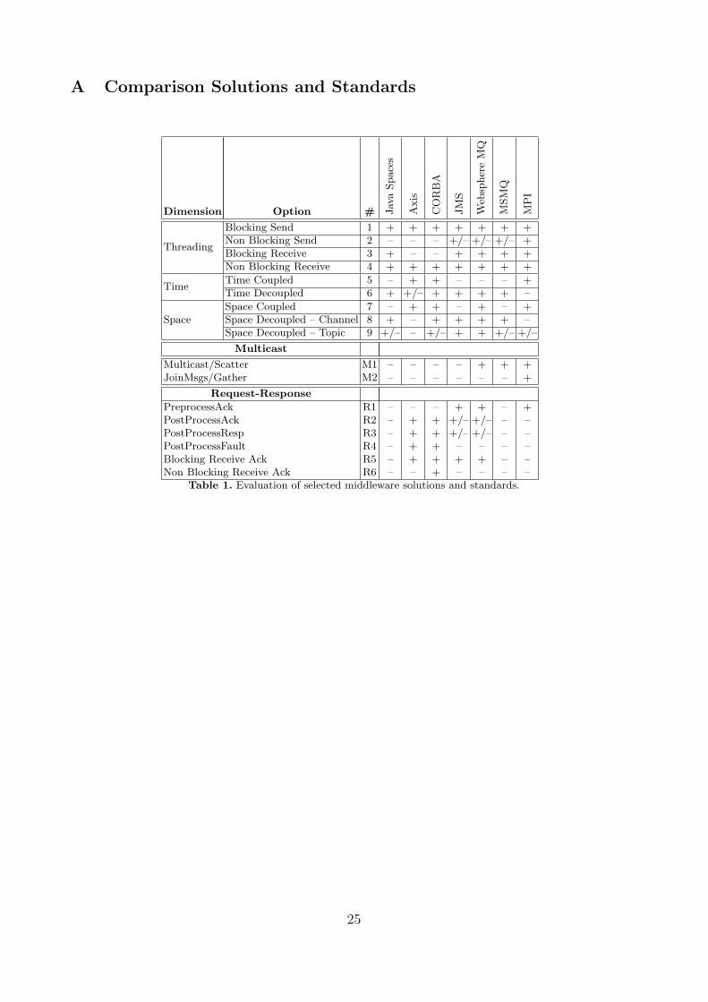
6 Comparison of Middleware Solutions and Standards
The concepts presented in this paper, are supported by a range of middleware solutions andstandards, but to varying degrees and in different combinations.
16
Therefore, in this section we propose that these concepts can be used to evaluate variousmiddleware solutions and standards. Such an evaluation may be of assistance to architectsdeciding between technologies based on the requirements with respect to levels of coupling ordecoupling between distributed systems. To illustrate this proposition, we have evaluated thefollowing: Java-spaces10, Axis [20], CORBA [3], JMS11, Websphere MQ12, MSMQ [10], andMPI13.
First of all it is important to establish that with any of these standards and solutions, it ispossible to implement all of the concepts. The question we are addressing is the relative level ofeffort required to achieve it. The results of this evaluation are presented in Table 1 in AppendixA. Solutions that directly support a pattern are given a plus (‘+’). Those able to support apattern using minor work-arounds are given a plus minus (‘+/–’), and those requiring greatereffort are assigned a minus (‘–’). A detailed rationale behind these assessments is provided inAppendix B.
In Table 1 Patterns C1 to C9 in the table represent the coupling integration patternspresented in Sections 3.1, 3.2, and 3.3. Patterns M1 and M2 represent the two patterns relatedto multicast and message joining presented in Section 3.3. Patterns R1 to R6 represent patternsof request-response as presented in Section 5.
Scenario - Mobile Devices and a BPM System. Consider a hospital that needs tointegrate a Business Process Management (BPM) system and a proximity sensor system tosend requests to medical staff based on their skills and location. Each medical staff is givena mobile device that relays location information to a central system. The BPM system usesthis information to allocate work items to perform patient care services in an efficient, timelymanner.
The challenge is to design an integration model accounting for the varying levels/types ofconnectivity between distributed systems, and mobile resources. Clearly the mobile devices willnot always be connected to the central system (due to varying levels of signal availability), andtherefore the use of non-blocking send is advisable. Hence messages to and from mobile devicescould be stored until the signal is restored. New mobile devices might need to be added to thesystem and device swapping may occur – which should not break the integration. Thereforespace decoupling is required, but we do not want to notify many instances of the same resourcewith the same work request, thus ruling out publish-subscribe. Finally, it is likely that themobile devices have intermittent connectivity and therefore time decoupling between mobiledevices and the central system is necessary.
Based on these requirements it is clear that one should use a combination of Pat-tern 2 (Non-blocking-send), Pattern 3/4 (Non-blocking-receive/Blocking-receive), and Pat-tern 6 (Time-decoupled). Combined this could amount to either configuration ‘C14’ (Non-blocking-send, Blocking-receive, Time-decoupled, Space-decoupled-channel) or configuration‘C16’ (Non-blocking-send, Non-blocking-receive, Time-decoupled, Space-decoupled-channel)from Appendix C.
The table (Table 1) shows that only JMS, Websphere MQ, and MSMQ could support sucha combination of requirements. Furthermore the table suggests a potential sticking point foreach of these solutions as they all only partially support Pattern 2 (Non-blocking-send).
10 Java Spaces http://java.sun.com/developer/products/jini/index.jsp, accessed March 2008.11 J2EE-SDK V. 1.4, http://java.sun.com/products/jms/, accessed March 2008.12 Websphere MQ V 5.1, [9].13 MPI Core: V. 2, [18].
17

7 Prototype
In the spirit of validating the proposal, we designed an API on top of the Java language,namely JCoupling. JCoupling was introduced in [19] as a means of enabling correlation ofmessages to instances of a business process through the use of properties, channels and filters.In this paper, we do not consider the issue of message correlation and filtering, focusing insteadon the coupling integration patterns and the request-response patterns. JCoupling combinesthe ideas presented in this paper with those presented in [7].
JCoupling is not a middleware per se: It does not provide application services traditionallyassociated with middleware such as reliable delivery (i.e. retries), transactions, security, etc.Its purpose is merely to illustrate how the proposed concepts can be used to support differenttypes of communication through a unified API. The source code of the prototype is availablefrom www.sourceforge.net/projects/jcoupling.
+createIntegrator() : Integrator
IntegratorFactory
+receiveRequest(in request) : RequestKey
+sendRequest() : MessageID
+...()
-communicatorID
Integrator
+blockingReceive(in dest, in timeout) : Msg +blockingReceive(in dest, in threshold, in timeout) : MsgsContainer +nonblockingReceive(in dest, in msgProcessor) : Future<T> +nonblockingReceive(in dest, in msgProcessor, in threshold) : List<Future<U>> +nonBlockingReceiveAsService(in dest, in msgProcessor) +...()
-subscriptions
Receiver
+...()
-type : DestType -uri : String
Destination
+blockingSend(in msg, in dest, in timeDecoupled) : ResponseContainer +blockingSend(in msg, in destSet, in timeDecoupled) : List<Future<ResponseContainer>> +nonBlockingSend(in msg, in dest, in timeDecoupled) : Future<ResponseContainer> +nonBlockingSend(in msg, in destSet, in timeDec : bool) : List<Future<ResponseContainer>> +...()
Sender
+...()
-id : MessageID -content -...
Msg
+getMsgID() : MessageID +getResponses()
-messageID
ResponseContainer
+getContent()
Response
1 1..*
0..1
1
0..1
1
-destination -integratorID
Subscription
1
0..*
Fig. 16. UML diagram showing key classes of the JCoupling API.
Figure 16 presents a summary of the JCoupling API. It can be seen from this figure thatthe abstract class Integrator is central to the JCoupling API. Concrete implementations ofIntegrator perform the transport responsibilities, required by any Sender and Receiver.For instance, a possible implementation of Integrator could enable interactions over TCPsockets. The JCouplingFactory interface provides a dynamic means of creating instances ofalternative implementations of the Integrator class. For instance an implementation of thisinterface could create either a JMS, TCP, or SOAP/HTTP Integrator implementation basedon the contents of a text-based configuration file.
As shown in Figure 16, the Integrator interface has two primary methods:
– receiveRequest() immediately returns a RequestKey identifying the interaction request,and then places the request onto the JCoupling server (which is not shown). When amessage is ready, on the JCoupling server, a call-back is made by the server onto the
18
requesting Integrator correlating the original request using the same key. This notifies theReceiver to retrieve the message off the server. The blocking or non-blocking interactionstyles are implemented within the Receiver, which is akin to the way they were modelledin the CPNs of previous sections.
– sendRequest() operates in a similar manner, except that a MessageID is used instead ofa request key, and that the client is a Sender.
Non blocking methods on both the Sender and the Receiver immediately returnjava.util.concurrent.Future objects. An object of type Future is essentially a handle toobtain a desired object once it is ready. The methods of Sender and Receiver that returnlists are concerned with multicast and aggregate message receival.
Example 1: Hello World. The following listings demonstrate the implementation of aninteraction using the Blocking-send, Blocking-receive, Time-decoupled, and Space-decoupled(Channel) patterns, as presented in Section 3. Such a coupling configuration mimics the com-mon behaviour observable in most Message Oriented Middleware.
Listing. 1. Performs a time-decoupled, space-decoupled, blocking-send.
1 ...
2 IntegratorFactory factory = new LocalIntegratorFactory();
3 try{4 Integrator integrator = factory.createIntegrator();
5 Sender sender = new Sender(integrator);
6 Channel channel = (Channel) integrator.lookup(CHANNEL_URI);
7
8 Message message = new Message();
9 message.setContent("Hello World");
10
11 sender.blockingSend(message, channel, TimeCoupling.decoupled);
12 } catch (JCouplingException e) { ... }
In Listing 1, line 2 creates a factory capable of instantiating Integrator objects, whichbasically allows client code to abstract away from the underlying transport protocol. Lines 5- 6 create the sender and obtain a reference to the channel. Line 11 sends the message overthis channel in a time-decoupled manner. Line 12 is needed because lines 4 and 11 can throweither a TransportException, NotFoundException, or a PermissionException (all sub-types ofJCouplingException).
Listing. 2. Performs a space-decoupled, blocking receive.
1 ...
2 try{3 Integrator integrator = factory.createIntegrator();
4 Receiver receiver = new Receiver(integrator);
5 Channel channel = (Channel) integrator.lookup(CHANNEL_URI);
6
7 Message message = receiver.blockingReceive(channel, Receiver.NEVER_TIMEOUT);
8
9 // At this point, the message has been received
10 ...
11 }12 catch (JCouplingException e) { ... }13 catch (TimeoutException e) { ... }
In Listing 2, lines 3 - 5 create the receiver, and obtain a reference to the channel. Line 7performs the receive - returning a Message object.
19
Example 2: “Scatter-gather”. A “scatter-gather” interaction is akin to an RPC Broadcast:given a collection of endpoints, a request is sent to each of these endpoints, and a response islater gathered from each of them. For demonstration purposes we will portray a purchase orderscenario. When a purchase order is received by Hardware-R-Us an inventory check reveals thatcertain line items are understocked. So Hardware-R-Us performs a scatter-gather request onthree wholesalers for a quote, with the best quote being pursued.
Hohpe and Woolf [11] propose an implementation of the scatter gather pattern using JMS.The endpoint playing the role of Hardware-R-Us sends a request onto a JMS topic, and eachwholesaler receives the request, creates a quote, parses the request for a return address, andposts the quote on the queue. The “Hardware-R-Us” endpoint receives each quote, one byone, keeping the best.
To implement the same scatter-gather using JCoupling requires less coding. Hardware-R-Us publishes a non-blocking-send, as shown in Listing 3.
Listing. 3. Publishes a search request to all libraries, and filters for the best responses.1 ...
2 try {3 IntegratorFactory factory = new LocalIntegratorFactory();
4 Integrator integrator = factory.createIntegrator();
5 Sender sender = new Sender(integrator);
6 Topic topic = (Topic) integrator.lookup(TOPIC_URI);
7
8 Message message = new Message();
9 message.setContent(BOOK_REQUEST);
10
11 Future<ResponseContainer> futureResponses =
12 sender.nonBlockingSend(message, topic, TimeCoupling.coupled);
13
14 ...// do something else while responses are coming back
15
16 ResponseContainer responseContainer = futureResponses.get();
17 List<Response> subscriberResponses = responseContainer.getResponses();
18 List<Response> goodResponses = filterResponses(subscriberResponses);
19 ...
20 } catch (JCouplingException e) { ... }21 catch (ExecutionException e) { ... }22 catch (InterruptedException e) { ... }
The wholesaler endpoints don’t need to explicitly receive messages, inspect return ad-dresses, and send replies, they only need to implement an interface and add it to a Receiver
object (Listings 4 and 5).
Listing. 4. The message processor interface.
1 public interface MessageProcessor<V>{2 public V processMessage(Message message) throws Exception;
3 public <U extends Serializable>U getResponse();
4 }
Implementations of MessageProcessor should provide the application logic needed toprocess the message, and to format a response. Method processMessage gets called first,then getResponse. The result of invoking getResponse gets returned to the sender.
Listing. 5. Creates a search receive/response server for a wholesaler.
1 try {2 IntegratorFactory factory = new LocalIntegratorFactory();
3 Integrator integrator = factory.createIntegrator();
20
4 Receiver receiver = new Receiver(integrator);
5 Topic topic = (Topic) integrator.lookup(TOPIC_URI);
6 receiver.subscribe(topic, TOPIC_PASSWORD);
7
8 QuoteRequestProcessor quoteRequestProcessor = new QuoteRequestProcessor();
9 receiver.nonBlockingReceiveAsService(topic, quoteRequestProcessor);
10 } catch (JCouplingException e) { ... }
In Listing 5, lines 4 - 6 create the receiver, obtain the topic reference, and subscribe thereceiver to the topic. Lines 8 - 9 instantiate an instance of the MessageProcessor interfaceand register it with the receiver. When a message arrives, the method processMessage ofQuoteRequestProcessor will be invoked (similar to onMessage in JMS).
8 Related Work
Cypher and Leu [2] provided a formal semantics of blocking/non-blocking send/receive whichis strongly related to our work. Their primitives were defined in a formal manner and relatedto the MPI [18]. This work does not consider space decoupling. Our research differs by com-bining thread-decoupling with the principles of time and space-decoupling (originating fromLinda [13]). Furthermore, our work unified these dimensions to define coupling integrationpatterns that can be used as a basis for middleware comparison.
Charron-Bost, Mattern, and Tel [21] provide a formalisation of the notions of synchronous,asynchronous, and causally ordered communication. This study introduces a notion of general-isation among these forms of communication according to sequences of messages at the globalperspective and cyclic dependencies between them. They propose an increasing gradation ofstrictness starting with asynchronous computation (akin to all forms of time-decoupled com-munication), through FIFO computations (akin to message sequence preservation), throughcausally ordered computations, and finally to the most strict form - synchronous computations(akin to thread-coupled, time-coupled communication). Their formalisation of “asynchronous”is akin to our notion of thread-decoupling; nevertheless they do not distinguish between time-decoupling and thread-decoupling as alternative forms of asynchronous communication. Thishighlights the fact that their work focusses on formal classifications of distributed messagesequences, while our is more architectural in nature. Their work does not address conceptssuch as space-decoupling, and only mentions request-response very briefly.
Thompson [22] described a technique for selecting middleware based on its communicationcharacteristics. Primary criteria include blocking versus non-blocking transfer. In this workseveral categories of middleware are distinguished, including conversational, request-reply,messaging, and publish-subscribe. The work, while insightful and relevant, does not attemptto provide a precise definition of the identified categories and fails to recognise subtle differenceswith respect to non-blocking communication. Our work, on the other hand contains precisedefinitions for blocking and non-blocking communication and it addresses the dimensions oftime and space.
Schantz and Schmidt [23] described four classes of middleware: Host infrastructure mid-dleware (e.g. sockets), Distribution middleware (e.g. CORBA [3], and RMI [24]), CommonMiddleware Services (e.g. CORBA and EJB), and Domain Specific Middleware Services (e.g.
21

EDI14 and SWIFT15). This classification provides a compelling high-level view on the spaceof available middleware. Their classification focusses on architectural concerns and domain-oriented criteria. While this classification does offer iportant differentiations bettwen alter-native forms of middleware it does not highlight these alternatives in terms of the couplingarchitectures available for each middleware alternative. Consequently our work can be con-strued to complement theirs.
Tanenbaum and Van Steen [25] described the key principles of distributed systems. Detailedissues were discussed such as (un-)marshalling, platform heterogeneity, and security. The workwas grounded in selected middleware implementations including RPC, CORBA, and the WorldWide Web. Our work is far more focussed on coupling at the architectural level, and thereforecomplements the technical issues discussed by Tanenbaum and Van Steen.
Barros et. al. [26] produced a set of service interaction patterns. The paper is orientedtowards the design and implementation of conversational Web services using process definitionlanguages such as the Business Execution Language for Web Services (BPEL4WS). However,these service interaction patterns do not deal with any notion of space/ time/ or threaddecoupling. Request-response interactions are briefly discussed but not incorporated into theother interaction patterns which overall tend to composed from many atomic interactions andmake use of state to arrive at more complex interaction patterns. The ideas are relevant butare highly distinct from our work.
9 ConclusionThis article has presented a set of formally defined notational elements to capture architecturalrequirements with respect to coupling. The proposed notational elements are derived froman analysis of middleware in terms of three orthogonal dimensions: (1) threading, (2) timeand (3) space. The patterns proposed in this work identify subtle differences between time-decoupling and thread-decoupling. Either time-decoupling or thread-decoupling, alone, can infact provide what is commonly regarded as asynchronous behaviour, somewhat overloadingthe term’s meaning; and yet in some middleware examples they are both present (e.g. MPI,JMS) – underlining their distinctness.
In this paper, we have argued that the terms ‘synchronous’ and ‘asynchronous’ are tooimprecise to constitute a foundation for defining models of integration. This inspired us todefine a set of coupling integration patterns that conceptualize the notions of synchronousand asynchronous communication, among others, in an unambiguous manner. We also linkedmulticast/join patterns, and six request-response patterns into the core concepts. This set ofpatterns unifies and organises existing knowledge in the domain of integration coupling. Wehave also presented an embodiment of the proposed concepts in the form of an API, namelyJCoupling.
Our key motivation for this paper was to address the lack of an overarching frameworkthat can unambiguously express architectural requirements with respect to (de-)coupling. Webelieve that the proposed coupling patterns introduced throughout this article offer a suffi-cient solution to this goal, and that the CPN models underpinning these patterns offer anunambiguous expression of their semantics.
14 EDI: Electronic Data Interchange is a set of standards defining electronic document structure for business to businesscommunication. There are two standards sets for EDI, one adopted by the ISO http://www.unece.org/trade/
untdid/welcome.htm, and one adopted by ANSI http://www.x12.org/ (accessed Jan 2007).15 SWIFT: Society for Worldwide Interbank Financial Telecommunication. SWIFT provide a value added network
enabling messages concerning transactions to be exchanged between banks of the world (http://www.swift.comaccessed Jan 2007).
22

In collaboration with Gecko (http://www.gecko.de/ accessed May 2008), we are currentlyworking on building a commercial form of the JCoupling API. We plan to add a middlewareaggregation layer to the implementation, allowing JCoupling to pass interaction requests overalternative forms of outward facing middleware, including JMS and WSDL-based implementa-tions. A meta-data layer will allow us to capture the semantics, programatically, of the outwardfacing middleware quite concisely, so that applications can “reason” about the semantics ofdifferent forms of middleware. As part of this work we intend to conduct load testing. We alsoreported in [19], some extensions to the JCoupling API to deal with message filters, and wehave shown how this enables the implementation of sophisticated forms of message correlationin the context of business process management systems. We are currently extending this workto integrate it into a workflow engine, namely YAWL [27].
Disclaimer The assessments we made of middleware products and standards with respect tothe coupling integration patterns are based on the tool or standard’s documentation and, insome cases, experimentation. They are true and correct to the best of our knowledge.
Acknowledgement This work was partly funded by an Australian Research Council Discov-ery Grant “Expressiveness Comparison and Interchange Facilitation between Business ProcessExecution Languages”.
References
1. Beugnard A, Fiege L, Filman R, Jul E, Sadou S. Communication Abstractions for Distributed Systems. ECOOP2003 Workshop Reader. Springer-Verlag, Berlin, volume 3013, 17 – 29.
2. Cypher R, Leu E. The Semantics of Blocking and Nonblocking Send and Receive Primitives. Siegel H, ed.,Proceedings of 8th International parallel processing symposium (IPPS). 729–735. URL citeseer.ist.psu.edu/
cypher94semantics.html.3. Group O M. Common Object Request Broker Architecture: Core Specification, 3.0.3 edition, 2004. http://www.
omg.org/docs/formal/04-03-01.pdf accessed Sep 2007.4. Hapner M, Burridge R, Sharma R, Fialli J, Haase K. Java Messaging Service API Tutorial and Reference. Addison-
Wesley, 2002.5. Jensen K. Coloured Petri Nets. Basic Concepts, Analysis Methods and Practical Use. Volume 1. EATCS mono-
graphs on Theoretical Computer Science. Springer-Verlag, Berlin, 1997.6. Rudolph E, Grabowski J, Graubmann P. Tutorial on Message Sequence Charts. Computer Networks and ISDN
Systems , 1996; 28(12): 1629–1641.7. Aldred L, Aalst W, Dumas M, Hofstede A. On the Notion of Coupling in Communication Middleware. Proceedings
of the 7th International Symposium on Distributed Objects and Applications (DOA). Springer Verlag, 1015 – 1033.8. Quartel D, Pires L F, van Sinderen M, Franken H, Vissers C. On the Role of Basic Design Concepts in Behaviour
Structuring. Computer Networks and ISDN Systems , 1997; 29(4): 413 – 436.9. Websphere MQ family. http://www-306.ibm.com/software/integration/wmq/ accessed Sept 2007.
10. Microsoft Message Queuing. http://www.microsoft.com/windowsserver2003/technologies/msmq/default.mspxaccessed Sept 2007.
11. Hohpe G, Woolf B. Enterprise Integration Patterns: Designing, Building, and Deploying Messaging Solutions.Addison-Wesley, Boston, MA, USA, 2003.
12. Eugster P, Felber P, Guerraoui R, Kermarrec A. The Many Faces of Publish/Subscribe. ACM Computing Surveys, 2003; 35(2): 114–131.
13. Gelernter D. Generative communication in Linda. ACM Trans. Program. Lang. Syst. , 1985; 7(1): 80–112. doi:http://doi.acm.org/10.1145/2363.2433.
14. Hoare C. Communicating Sequential Processes. Prentice-Hall, Englewood Cliffs, 1985.15. Milner R. Communicating and Mobile Systems: The Pi-Calculus. Cambridge University Press, Cambridge, UK,
1999.16. CPN Tools homepage. http://wiki.daimi.au.dk/cpntools/ accessed Sept 2007.17. Milner R, Tofte M, Harper R, MacQueen D. The Definition of Standard ML - Revised. MIT Press, Cambridge,
USA, 1997.18. Snir M, Otto S, S Huss-Lederman D W, Dongarra J. MPI-The Complete Reference: The MPI Core. MIT Press,
second edition, 1998.
23

19. Aldred L, Aalst W, Dumas M, Hofstede A. Communication Abstractions for Distributed Business Processes.Proceedings of the 19th International Conference on Advanced Information Systems Engineering. Springer Verlag,volume 4495 of Lecture Notes in Computer Science, 409–423.
20. Apache Axis homepage. http://ws.apache.org/axis/ accessed Sept 2007.21. Charron-Bost B, Mattern F, Tel G. Synchronous, asynchronous, and causally ordered communication. Distributed
Computing , 1996; 9(4): 173–191.22. Thompson J. Toolbox: Avoiding a Middleware Muddle. IEEE Software , 1997; 14(6): 92–98.23. Schantz R, Schmidt D. Encyclopedia of Software Engineering, Wiley & Sons, New York, USA, chapter Middleware
for Distributed Systems: Evolving the Common Structure for Network-centric Applications, 2002; .24. Microsystems S. Java Remote Method Invocation Specification. http://java.sun.com/j2se/1.5.0/docs/guide/
rmi/spec/rmiTOC.html accessed Sept 2007.25. Tanenbaum A, M van Steen. Distributed Systems: Principles and Paradigms. Prentice Hall PTR, Upper Saddle
River, NJ, USA, 2001.26. Barros A, Dumas M, Hofstede A. Service Interaction Patterns. Proceedings of the 3rd International Conference on
Business Process Management (BPM). Springer Verlag, 302–318.27. YAWL Home Page. http://www.yawlfoundation.com accessed June 2008.
24
A Comparison Solutions and Standards
Dimension Option # Jav
aSpace
s
Axis
CO
RB
A
JM
S
Web
spher
eM
Q
MSM
Q
MP
I
Threading
Blocking Send 1 + + + + + + +Non Blocking Send 2 – – – +/– +/– +/– +Blocking Receive 3 + – – + + + +Non Blocking Receive 4 + + + + + + +
TimeTime Coupled 5 – + + – – – +Time Decoupled 6 + +/– + + + + –
SpaceSpace Coupled 7 – + + – + – +Space Decoupled – Channel 8 + – + + + + –Space Decoupled – Topic 9 +/– – +/– + + +/– +/–
Multicast
Multicast/Scatter M1 – – – – + + +JoinMsgs/Gather M2 – – – – – – +
Request-Response
PreprocessAck R1 – – – + + – +PostProcessAck R2 – + + +/– +/– – –PostProcessResp R3 – + + +/– +/– – –PostProcessFault R4 – + + – – – –Blocking Receive Ack R5 – + + + + – –Non Blocking Receive Ack R6 – – + – – – –
Table 1. Evaluation of selected middleware solutions and standards.
25

B Rationale behind the evaluation of Standards and Tools againstthe Patterns
Table 1 presented an evaluation of middleware standards and tools, in terms of their abilityto directly support or partially support the coupling capabilities presented in this article.Solutions that directly support a pattern were given a plus (‘+’). Those able to support apattern using more than a little effort were given a plus minus (‘+/–’), and those requiringgreater effort were assigned a minus (‘–’). A ‘–’ symbol, assigned to a standard/solution,does not mean that the achievement of this pattern is impossible; rather, the ‘work-arounds’necessary to achieve the pattern, using this standard/solution, are non-trivial.
B.1 Java Spaces
Java Spaces supports a blocking-send through its write operation. However it does not supporta non-blocking send, hence capability ‘2’ was given a ‘–’ in Table 1.
Java Spaces supports blocking-receive through its read or take operations, and supportsnon-blocking receive through its notify operation, hence capabilities ‘3’ and ‘4’ were assigneda ‘+’ in Table 1.
Java Spaces, is time-decoupled, and is not time-coupled. Consequently capability ‘5’ wasassigned a ‘–’ in Table 1.
Java Spaces supports space-decoupling over a channel, but does not support coupling onesender to one receiver, hence a ‘–’ for capability ‘7’ in Table 1.
Space-decoupling over a topic (e.g. publish-subscribe) is partially achieved if each ‘sub-scriber’ uses a read operation. Each receiver gets a copy of the message because the call toread does not remove the message from the space. Hopefully the message will be removedfrom the space before any receiver reads the same message twice. A simple, but not fail-safe‘work-around’ to prevent this problem is to write the message to the space with a very shortlease.
Java Spaces does not provide primitives for sending messages over an arbitrary set oftemplates, and we therefore rule out multicast. We rule out support for message joining becauseit does not support its take, or read operations over arbitrary sets of templates.
Java Spaces does not directly support responses, therefore patterns R1 – R6 of Table 1were assigned a ‘–’.
B.2 Axis
Axis is a SOAP engine that primarily uses HTTP as a transport. Like HTTP, it only offersa blocking-send, and a non-blocking-receive. Despite the fact that Axis can be configured touse JMS as a message transport service, it does not expose a non-blocking send or a blocking-receive in its API. Consequently non-blocking send and blocking receive were assigned a ‘–’ inTable 1.
Axis, supports time-coupling but only when layered over a JMS implementation could itpossibly support time-decoupling.
Axis directly supports space-coupling, but does not support space-decoupling. Despitethe fact that JMS supports space-decoupling over channels and topics Axis does not exposeconstructs that allow users to exploit either of these features. Consequently, in Table 1, items‘8’ and ‘9’ were assigned ‘–’.
Axis provides no direct support for multicast, or for message joining.
26

Axis supports many form of acknowledgement, hence it was well represented in the list ofitems of Table 1 related to responses. Nevertheless, preprocess acknowledgement (R1) is notsupported. A ‘work-around’ solution would require forking off a thread in the server to processthe message while sending a receipt acknowledgement in the response from the main thread.Non-blocking receive of responses is not possible without using callbacks, hence it is assigned‘–’ in Table 1.
B.3 CORBA
CORBA supports a blocking-send because the CORBA client blocks on remote object calls,at least until the request has reached the ORB. It supports non-blocking-receive because theremote object servicing requests never makes an explicit request to wait for an incomingrequest, this gets managed by the ORB. Nevertheless, CORBA provides no direct support fora non-blocking-send or a blocking-receive operation.
CORBA traditionally offers a time-coupled means of interacting, and using what it refersto as an ‘asynchronous’ style it provides direct support for time-decoupled interactions.
CORBA’s naming service is the primary way to address remote objects. The naming servicemaps a name to one remote object, as opposed to one of many, hence CORBA directly supportsspace-coupling. CORBA allows clients to obtain remote object references using InteroperableObject Group Reference (IOGR). This sort of remote object reference refers to one of manyobject implementations, and therefore CORBA supports space-decoupling over a channel.CORBA also has support for publish-subscribe, but achieving this style of interaction is notas straightforward as it should be, and therefore we consider that it only partially supportsthis (see Table 1).
CORBA does not directly support multicast or message joining hence we gave it ‘–’ forM1 and M2 of Table 1.
CORBA, like Axis would require thread forking techniques to provide the requestor withan acknowledgement before the request gets processed, therefore we gave response patternR1 a ‘–’ in Table 1. Otherwise CORBA has the best representation of any of the solutionsor standards evaluated for supporting the various forms of response, and that is reflected inTable 1.
B.4 Java Message Service
The JMS standard directly supports blocking-send, blocking-receive, and non-blocking receive.However, it does not directly support non-blocking send. Nevertheless, most implementationsof JMS can be configured with a sender, and middleware service on the same machine. Themessage is passed into the middleware service and then is put over the network without thesender needing to wait. Hence we assign JMS a ‘+/–’ for item ‘2’ in Table 1.
JMS, being a MOM driven standard, natively supports time-decoupling but not time-coupling. Hence a ‘–’ for item ‘5’.
JMS supports both forms of space-decoupling (channel and topic), but not space-coupling.Consequently item ‘7’ in Table 1 was assigned a ‘–’.
JMS, however does not support either of the multicast/join patterns.JMS is not a request-response driven standard, but despite this it supports preprocess
acknowledgements (R1) directly via session acknowledgements. It supports blocking-receiveacknowledgements (R5) directly through its QueueRequestor and TopicRequestor classes.Post-process acknowledgements (R2) and post-process responses (R3) are supported through
27

the same classes. However, we deem this support only partial (‘+/–’) due to the need to parsefor a return address and begin a new interaction at the responder (as discussed in Section 5).
B.5 Websphere MQ
Websphere MQ is the MOM component of the Websphere suite, by IBM. Websphere MQprovides an implementation of the JMS standard and, of course, supports every pattern thatJMS covers.
Additionally, Websphere MQ allows the configuration of one particular endpoint to exclu-sively receive messages off a channel. Therefore Websphere MQ fully supports space-coupling.Consequently item ‘7’ in Table 1 was assigned a ‘+’.
B.6 MSMQ
MSMQ is the MOM implementation by Microsoft. It provides MOM support to the BizTalkprocess application server and to the new Windows Communication Foundation.
MSMQ directly supports blocking-send, blocking-receive, and non-blocking receive. How-ever, like the JMS, it does not directly support non-blocking send. Nevertheless the samework-around to achieve non-blocking send for JMS can be performed using MSMQ. Hence weassign MSMQ a ‘+/–’ for item ‘2’ in Table 1.
MSMQ, like most MOM solutions does not support time-coupling. Hence we assigned a ‘–’to items ‘5’ and ‘6’ in Table 1.
MSMQ has full support for space-decoupling over a channel but would require non trivial‘work-arounds’ to achieve space-coupling. Therefore we assigned MSMQ a ‘–’ for item ‘7’ inTable 1.
With respect to space-decoupling over a topic MSMQ offers a peek operation in its API –allowing receiver endpoints to peek at messages in the queue. Using peek to support space-decoupling over a topic (or publish-subscribe) is a work-around, in much the same class asJava spaces. Therefore, it was assigned a ‘+/–’ for item ‘9’ in Table 1.
MSMQ, supports multicast directly but to our knowledge does not support multicast/join,or any of the request-response patterns.
B.7 MPI
The Message Passing Interface, developed by a consortium of leading IT vendors and selectmembers of the research community, was designed to enable parallel and distributed systems toexchange messages effectively. Using MPI, parallel applications are able to exploit processingon multiple CPUs for example, because the API is extremely efficient in its use of memory andthe CPU. MPI fully supports all forms of thread (de-) coupling, providing explicit operationsfor blocking-send, non-blocking send, blocking-receive, and non-blocking receive – as is shownin Table 1.
MPI does not support time-decoupling – as shown in Table 1. MPI does not support space-decoupling over a channel. MPI is able to notify all members of a group with copies of the samemessage. This behaviour is strongly related to space-decoupling over a topic, however thesegroups are determined during build-time, or design-time. There seems to be limited supportfor joining a group at runtime, and no support for joining more than one group. We thereforerated MPI a ‘+/–’ for Space-decoupled (Topic).
MPI fully supports multicast, message joining and preprocess acknowledgement.
28

C Composing the Dimensions Graphically - An Enumeration
To create a graphical representation of a coupling configuration the graphical notations asso-ciated with each of the nine coupling patterns presented in Section 3 can be used a startingpoint. They are, more or less, obtained by “overlaying” the notations for decoupling introducedin Section 3. As stated in Section 4, there are twenty-four possible combinations of these ninepatterns, given that they represent points on different dimensions, or vectors. These graphicalnotations extend Message Sequence Charts [6].
C1) Blocking-send, Blocking-receive, Time-coupled, Space-
coupled
C4) Non-blocking-send, Non-blocking-receive, Time-coupled,
Space-coupled
C5) Blocking-send, Blocking-receive, Time-decoupled, Space-
coupled
C6) Non-blocking-send, Blocking-receive, Time-decoupled, Space-coupled
A B
A B
A B
C2) Non-blocking-send, Blocking-receive, Time-coupled, Space-
coupled
C3) Blocking-send, Non-blocking-receive, Time-coupled, Space-
coupled
C7) Blocking-send, Non-blocking-receive, Time-decoupled, Space-coupled
C8) Non-blocking-send, Non-blocking-receive, Time-decoupled, Space-
coupled
A B
A B
A B
A B A B
Fig. 17. Notations for the coupling integration configurations – space-coupled communication.
Figures 17, 18, and 19 present these combined notations.
29

C9) Blocking-send, Blocking-receive,Time-coupled, Space-decoupled-
channel
C10) Non-blocking-send, Blocking-receive, Time-coupled, Space-
decoupled-channel
C14) Non-blocking-send, Blocking-receive, Time-decoupled, Space-
decoupled-channel
A B A B
C11) Blocking-send, Non-blocking-receive, Time-coupled, Space-
decoupled-channel
A B
C12) Non-blocking-send, Non-blocking-receive, Time-coupled, Space-
decoupled-channel
A B
C13) Blocking-send, Blocking-receive, Time-decoupled, Space-
decoupled-channel
C15) Blocking-send, Non-blocking-receive, Time-decoupled, Space-
decoupled-channel
C16) Non-blocking-send, Non-blocking-receive, Time-decoupled, Space-
decoupled-channel
A B A B
A B A B
Fig. 18. Notations for the coupling integration configurations – Space-decoupled (Channel).
30
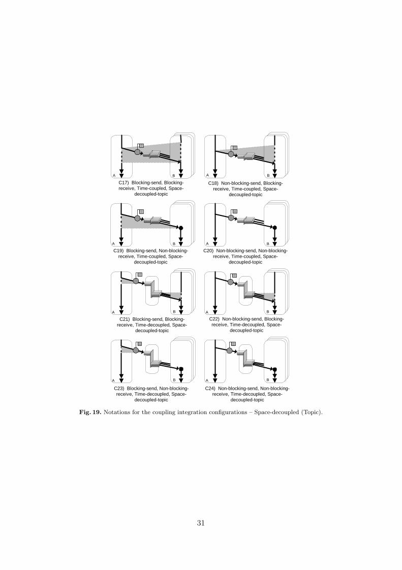
C17) Blocking-send, Blocking-receive, Time-coupled, Space-
decoupled-topic
C18) Non-blocking-send, Blocking-receive, Time-coupled, Space-
decoupled-topic
C22) Non-blocking-send, Blocking-receive, Time-decoupled, Space-
decoupled-topic
A B A B
C19) Blocking-send, Non-blocking-receive, Time-coupled, Space-
decoupled-topic
A B
C20) Non-blocking-send, Non-blocking-receive, Time-coupled, Space-
decoupled-topic
A B
C21) Blocking-send, Blocking-receive, Time-decoupled, Space-
decoupled-topic
C23) Blocking-send, Non-blocking-receive, Time-decoupled, Space-
decoupled-topic
C24) Non-blocking-send, Non-blocking-receive, Time-decoupled, Space-
decoupled-topic
A B A B
A B A B
Fig. 19. Notations for the coupling integration configurations – Space-decoupled (Topic).
31

D Extended CPNs and Simulation
Figure 20 presents a combination of a Blocking-send, and a Blocking-receive CPN - extended- to include a timeout. Either the sender or the receiver can timeout before the interactionhas completed. Some new places, transitions and arcs were added (indicated in Grey) toperform timeouts. Note that the structure of the original CPNs (Figs. 1(b) and 3(b)) has beenpreserved. Nevertheless, we extended the colours Thread and Msg to timed (see 1 in Fig. 20).We also extended some arcs with timed expressions (see 2). The timed expression msg@+m
adds m time units to the token msg. Variable m is declared as a random number between 4 and7 (colset M = int with 4..7). This range of values was chosen for simulation purposes insuch a way that the timeout may or may not occur. When the token msg is timed any transitionit enables will not be allowed to fire until the current time equals m. We also changed two arcsto carry multiple tokens (see 3).
Change (3) was necessary because if a timeout occurred in the sender (removing a tokenfrom the place “in progr”) we need to clean up the incomplete interaction for the receiver (andvice versa). Put another way, if a timeout occurs during message transit for one endpoint themodel must allow the other endpoint to timeout gracefully – preventing deadlock. Technically,using two tokens as shown by change (3) allows this.
�
�� � � �
�
� � � �
� � � � ��
� � �
� � �
� � � � � �
� � �� � � � � �
�
� � �
� � � � � �� � � �
� � � � � � � � � � � �
� � � � � � � �� � � � � � �
� � � � � �� � � �� � � � � �
� � �� � � � �
� � � � � � � � � � �
� � � � �� � � � �
� � � � � �
� � � � � � � �� � � �
�
�
�
� � � �
� � � � � � �� � � � ! " � � � � � �
# �� � � � � � �
� � � � � �
� � � � �$ � �
� � � � � �� � � � � � �
� � �� � � � %
" � � � � � �
� �� � � � � � �� �
� � � �$ � �
� � � � & �$ � �
� � �� � � � '� �
� � � � � �
� � �� � � � %
� � � � !
$ � �
� � � � � � � � � � �
� � � � � � � � � � � �
� � � � � �� � � �
� � � �
Fig. 20. Blocking-send, Blocking-receive with timeouts.
Using CPN tools we ran 40 simulations of this CPN. We found that there were threepossible outcomes.
Timed-out, no interactions before the transition “fin x-port” had the time to fire – com-pleting an interaction – both of the transitions “Timeout send” or “Timeout recv” fired.
Timed-out, some completed interactions at least one interaction completed such thattransition “fin x-port” fired.
All completed interactions before any time-out transition could fire, all interactions werecompleted.
The delay to fire a transition (that progresses an interaction) was produced using a randomvalue in the range of m (e.g. msg@+m). This value influenced the interaction speed. The delay
32
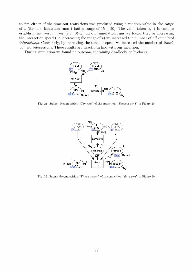
to fire either of the time-out transitions was produced using a random value in the rangeof i (for our simulation runs i had a range of 15 .. 20). The value taken by i is used toestablish the timeout time (e.g. t@+i). In our simulation runs we found that by increasingthe interaction speed (i.e. decreasing the range of m) we increased the number of all completedinteractions. Conversely, by increasing the timeout speed we increased the number of timed-out, no interactions. These results are exactly in line with our intuition.
During simulation we found no outcome containing deadlocks or livelocks.
�
�
� � �� � � � � � � �
�� � � � � �
� � � �� � �
� ��
� � � �� � ��
� � �� �
� � ��
� �
� �
� � �� � �� � � � � �� � �
�
�
�
� � �
�
Fig. 21. Subnet decomposition “Timeout” of the transition “Timeout send” in Figure 20.
� � ��
�
�
�
� � �
� � �
� � � � �
� � �� �
� � � � �
� � � � �� � � � � �
� � � � � � �
� � �� � � �
� � �
� �
� � � �
� �� � � � �� � �
� �� � � �
� �� � � �� �
� � � � �� � � �
� �� �� � � �
� �� � � �
� �� �� � � �
� � � �� �
� � �
� � �
� � �
Fig. 22. Subnet decomposition “Finish x-port” of the transition “fin x-port” in Figure 20.
33