diminishing manufacturing sources and material shortages ... · pdf fileoperations impact...
TRANSCRIPT

Diminishing Manufacturing Sources and Material Shortages (DMSMS)
Guidebook
April 7, 2005

FORWARD
This Department of Defense (DoD) Diminishing Manufacturing Sources and Material Shortages (DMSMS) Guidebook is a compilation of the best proactive practices from across DoD Services and Agencies for managing the risk of obsolescence. With material extracted from various DoD DMSMS management documents, this DoD DMSMS Guidebook provides the DMSMS Program Manager (PM) with a central repository of best practices. Additionally, it identifies assorted measurement tools that may be useful in analyzing and tracking the effectiveness of DMSMS Programs. The DMSMS PM should make this guidebook the desktop reference to quickly pinpoint key actions required in managing DMSMS issues and concerns.
ii

TABLE OF CONTENTS TABLE OF CONTENTS.................................................................................................... 1 1. INTRODUCTION ...................................................................................................... 2 2. ENCOMPASSING TOTAL LIFE CYCLE SYSTEM MANAGEMENT and PERFORMANCE BASED LOGISTICS TENETS............................................................ 3 3. ESTABLISHING A DMSMS PROGRAM................................................................ 5
3.1. Determining Level of Involvement..................................................................... 5 3.1.1. Implementation Intensity Levels................................................................. 6 3.1.2. Selection of Practices.................................................................................. 7 3.1.3 Expanded Discussion of the 3+ Level Approach...................................... 10
3.2. Key Program Elements to Consider.................................................................. 12 3.2.1 Program Implementation .......................................................................... 12 3.2.2 DMSMS Program Elements ..................................................................... 13 3.2.3. The B-2 Bomber DMSMS Management Program ................................... 18 3.2.4 The GPS DMSMS Management Program................................................ 18 3.2.5 Shared Data Warehouse............................................................................ 18 3.2.6 The DMSMS Center of Excellence (COE)............................................... 19
3.3 Bill of Materials (BOM) Development............................................................. 19 3.4 Resolution Alternatives by Acquisition Lifecycle Phase.................................. 21
3.4.1 Alternatives Through the System Life Cycle Phase ................................. 21 3.4.2 Resolution Definitions .............................................................................. 22 Depicting Resolution Frequency............................................................................... 26
4. ANALYZING RESULTS (MEASURES)................................................................ 27 4.1 Introduction....................................................................................................... 27 4.2 OSD Criteria for DMSMS Program Rating...................................................... 27
4.2.1. OSD Color-Coded Rating Scheme ........................................................... 27 4.2.2 OSD Tracking and Accounting for DMSMS Programs ........................... 28
4.3 Cost ................................................................................................................... 28 4.3.1 Resolution Cost Trade-Off Studies........................................................... 28 4.3.2. Cost Avoidance......................................................................................... 29 4.3.3. Business Case Analysis (BCA)................................................................. 33 4.3.4. Funding Impact ......................................................................................... 36
4.4. Schedule............................................................................................................ 36 4.4.1 Timeline .................................................................................................... 36
4.5. Performance ...................................................................................................... 37 4.5.1. Operations Impact Analysis (OIA) ........................................................... 37 4.5.2. Platform Readiness Status......................................................................... 39 4.5.3. Table of Various Performance Measures.................................................. 41 4.5.4. Design Interface Criteria Evaluation ........................................................ 42
5. ACRONYMS............................................................................................................ 43 6. REFERENCES ......................................................................................................... 46
1

1. INTRODUCTION There are three goals for developing the DOD DMSMS Guidebook,
• Define a proactive DMSMS management process that can be used by Program Managers (PMs) to build an effective DMSMS Program.
• Define DMSMS support metrics to measure the effectiveness of a proactive DMSMS Program.
• Promote cost-effective supply chain management integrity through DMSMS problem resolution at the lowest (cost, time, functional) level.
An effective DMSMS process:
• Ensures that all parts and material to produce, or repair, the platform are available
• Reduces, or controls, Total Ownership Costs (TOC)
• Minimizes Total Life Cycle System Management (TLCSM) cost
• Eliminates, or at least minimizes, reactive DMSMS actions
• Evaluates design alternatives
• Provides for risk mitigation as it applies to DMSMS
• Utilizes more than one approach to resolve DMSMS issues
• Collects metrics
Common practices developed by various DoD organizations to achieve these goals and results are presented in this document for consideration. This Guidebook is not predisposed to any particular type of manufacturing sources and/or material shortages.
2

2. ENCOMPASSING TOTAL LIFE CYCLE SYSTEM MANAGEMENT (TLCSM) and PERFORMANCE BASED LOGISTICS (PBL) TENETS The “DoD Template for Application of TLCSM and PBL in the Weapon System Life Cycle” stresses the tenets that emphasize an early focus on sustainment within the system life cycle. TLCSM is the implementation, management, and oversight, by the designated PM, of all activities associated with the acquisition, development, production, fielding, sustainment, and disposal of a DoD weapon system across its life cycle. It empowers the PM as the life cycle manager with full accountability and responsibility for system acquisition and follow-on sustainment. PBL is the preferred sustainment strategy for weapon system product support, and employs the purchase of support as an integrated, affordable performance package designed to optimize system readiness. An efficient, proactive DMSMS management process is critical to providing more effective, affordable, and operationally ready systems by increasing availability and supportability. This is in line with the TLCSM and PBL tenets. On contracts invoking PBL, where a contractor provides product support, the contractor must be required to initiate and maintain a proactive DMSMS Program. The contractor is then held bound by contract metrics that require sound DMSMS practices be integrated into all phases of the acquisition process pertaining to the work effort. The objective with PBL contracts is to ensure that the PBL provider is held fully accountable for resolving DMSMS or obsolescence issues. Ideally, PBLs are long term (5-15 years), firm fixed priced, cost per unit usage contracts and require that the provider manages many aspects of product support through the life cycle. As such, the properly structured PBL will include an inherent incentive for the provider to be proactive and manage DMSMS and obsolescence in order to achieve the required performance outcome(s). These long term PBL agreements/contracts lower provider risk and allow for DMSMS mitigation efforts: life of type buys, establishment of long term contracts with subcontractors, and return on investment for redesigns. Additionally, A PBL provider may be able to leverage off of their commercial divisions. This Guidebook provides proven examples of practices that can be initiated to attain that end. The TLCSM approach increases the significance of design for system Reliability, Availability, Maintainability, Manufacturability, and Supportability. The inherent objective of the TLSCM is to enhance war fighter’s capability through improved System Operational Effectiveness (SOE) of new and fielded weapon systems. SOE is a composite of performance, availability, process efficiency, and total ownership cost. The objectives of the SOE concept can best be achieved through influencing early design and architecture. The war fighter’s capabilities are maximized by focusing on System Design for Operational Effectiveness (SDOE) through the DMSMS application of cost-effective Lean Six-Sigma principles. Reliability, reduced logistics footprint, and reduced system life cycle cost/total ownership cost (TOC) are most effectively achieved through inclusion from the very beginning of a program – starting with the definition of required capabilities. Reliability, Maintainability, Supportability, and Producability are components that impact availability. The primary objective of ‘design for system
3

supportability’ is to positively impact and reduce the requirements for the various elements of logistics support during the system operations and maintenance phase. One aspect of successfully accomplishing this is by addressing issues pertaining to DMSMS.1 Open systems design helps mitigate the risks associated with technology obsolescence. Being locked into proprietary technology or relying on a single source of supply over the life of a system can be detrimental to the war fighter’s mission. Spiral development can also help to alleviate obsolescence concerns. However, the PM must ensure that PBL product support efforts include an active DMSMS process to anticipate occurrences and take appropriate action. When a PBL contract is used the PM must ensure the exit criteria calls for all configuration management data to be turned over to the Government. The Product Support Integrator (PSI) can often carry this out.2 PBL support arrangements give significant latitude to the PSI to manage technology refreshment. PSIs have responsibility for performance outcomes and are incentivized to maintain currency with state-of-the-art technology, maximize the use of Commercial Off-The-Shelf (COTS) items, and generally use readily available items to avoid the high cost of DMSMS over the life of the system3. Actively addressing DMSMS concerns throughout the entire life of the program will help ensure effective life cycle support and reduce adverse impacts on readiness or mission capability.
4
3. ESTABLISHING A DMSMS PROGRAM
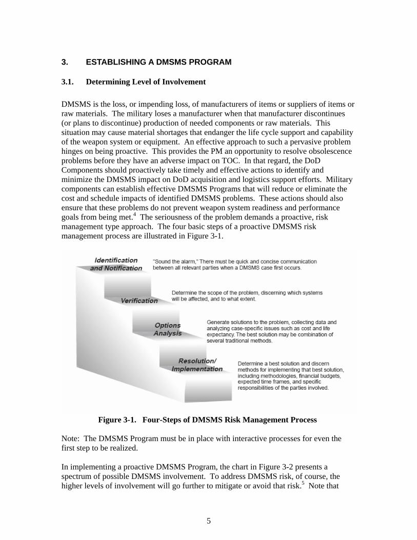
3.1. Determining Level of Involvement DMSMS is the loss, or impending loss, of manufacturers of items or suppliers of items or raw materials. The military loses a manufacturer when that manufacturer discontinues (or plans to discontinue) production of needed components or raw materials. This situation may cause material shortages that endanger the life cycle support and capability of the weapon system or equipment. An effective approach to such a pervasive problem hinges on being proactive. This provides the PM an opportunity to resolve obsolescence problems before they have an adverse impact on TOC. In that regard, the DoD Components should proactively take timely and effective actions to identify and minimize the DMSMS impact on DoD acquisition and logistics support efforts. Military components can establish effective DMSMS Programs that will reduce or eliminate the cost and schedule impacts of identified DMSMS problems. These actions should also ensure that these problems do not prevent weapon system readiness and performance goals from being met.4 The seriousness of the problem demands a proactive, risk management type approach. The four basic steps of a proactive DMSMS risk management process are illustrated in Figure 3-1.
Figure 3-1. Four-Steps of DMSMS Risk Management Process
Note: The DMSMS Program must be in place with interactive processes for even the first step to be realized. In implementing a proactive DMSMS Program, the chart in Figure 3-2 presents a spectrum of possible DMSMS involvement. To address DMSMS risk, of course, the higher levels of involvement will go further to mitigate or avoid that risk.5 Note that
5

these four levels of involvement do not necessarily equate to the four-step risk management process discussed in section 3.1. or to the intensity levels discussed in section, 3.1.1.
Figure 3-2. DMSMS Risk Management Practices
3.1.1. Implementation Intensity Levels 3.1.1.1. Intensity Levels Defined. There are four intensity levels of common practices influenced by the resources available to manage DMSMS. These include practices that could be implemented to mitigate the effect of DMSMS and are defined as:
a. Level 1: Practices implemented to resolve current obsolescence problems. Some of these activities may be considered reactive. b. Level 2: Minimal required practices necessary to mitigate the risk of future obsolete items. The majority of these activities are perceived as proactive. c. Level 3: Advanced practices required to mitigate the risk of obsolescence when there is a high opportunity to enhance supportability or reduce total cost of ownership. These proactive activities may require additional program funding. d. Level 3+: Proactive practices implemented during conceptual design and continuing through production and fielding of new start systems.
3.1.1.2. The Role of Proactive Management. The common practices in Table 3-1 anticipate future events and establish program elements to mitigate future problems. The practices associated with the above intensity levels form the basis of a possible DMSMS
6

Management Program that can be used to mitigate the impact of DMSMS. Level 3+ is introduced to establish initial planning, preferably during the early stages of design that will realize significant benefit to the fielded system for its expected lifetime. These proactive design and documentation practices will provide the most cost-effective, concise technical information required for long-term sustainment with the least cost.
Table 3-1. Common Practices
Intensity Level 1 Intensity Level 2 Intensity Level 3 Intensity Level 3+
DMSMS Focal Point Awareness Training Circuit Design Guidelines
Technology Road Mapping
Awareness Briefing DMSMS Prediction VHDL 1 Planned System Upgrades
Internal Communications DMSMS Steering Group
Technology Assessment
Technology Insertion
External Communications COTS List EDI 2 Technology Transparency
DMSMS Plan DMSMS Solution Database
Technology Insertion
VHDL
Parts List Screening Opportunity Index Programmable Logic Devices
Parts List Monitoring Website Resolution of Current Items
Operational Impact Analysis
Supportability Checklist Notes: 1. VHDL: Very High Speed Integrated Circuit (VHSIC) Hardware Definition Language 2. EDI: Electronic Data Interchange
3.1.2. Selection of Practices 3.1.2.1 Trigger Events. The consideration and selection of DMSMS management practices usually follows an event that convinces the program manager that one or more practices need to be implemented. These events are called triggers. Qualitative triggers form the basis of the questionnaire shown in Table 3-2. To assess the situation, PMs should complete the questionnaire in Table 3-2. Quantitative triggers form the basis of the selection process shown in Figure 3-3. PMs who have been faced with a DMSMS problem may well want to use both the questionnaire and the selection process in Table 3-2 and Figure 3-3, respectively. Reactionary actions, based upon triggers, usually do not yield the best design, nor do they apply Lean Six-Sigma principles, thus resulting in a cost ineffective remedy. A proactive program uses DMSMS tools to evaluate parts data (PPL/BOM), project potential issues and evaluate alternative solutions.
7

Table 3-2. Common Practices Selection Questionnaire
Question Number Question to Program Manager
If Yes, Review Intensity Level(s)
1 Is there an opportunity to enhance supportability or reduce TOC? 1, 2, and 3 2 Are you in the early stages of design? 3+ 3 Has higher management (above PM) become aware of supportability
problems? 1 and 2
4 Have you increased your awareness of DMSMS problems? 1 5 Have you recently become aware of DMSMS problems? 1
NoNo
No No
Yes
Select CommonPractice
Ei
ther
>20 Years Remainingin System Lifecycle?
Review Levels 2and 3 Practices
Yes>20% of PartsUnsupportable?
PartsIssue?
SystemAge?
New Development?Yes
Review Level 3+Practices
YesNotice of Discontinuance?
10-20 Years Remainingin System Lifecycle?
YesReview Levels 1and 2 Practices
Yes10-20% of PartsUnsupportable?
<10 Years Remainingin System Lifecycle?
YesReview Level 1 Practices
Yes<10% of PartsUnsupportable?
No No
NoNo
No No
YesYes
Select CommonPractice
Either
Select CommonPractice
EitherEither
>20 Years Remainingin System Lifecycle?
Review Levels 2and 3 Practices
Yes>20% of PartsUnsupportable?
PartsIssue?
SystemAge?
New Development?Yes
Review Level 3+Practices
YesNotice of Discontinuance?
10-20 Years Remainingin System Lifecycle?
YesReview Levels 1and 2 Practices
Yes10-20% of PartsUnsupportable?
<10 Years Remainingin System Lifecycle?
YesReview Level 1 Practices
Yes<10% of PartsUnsupportable?
No No
Figure 3-3. Selection Process When the Extent of DMSMS Problems is Known
3.1.2.2. In addition to using the questionnaire in Table 3-2 and the selection process in Figure 3-3, the selection of the appropriate practices must also consider the complexity of the program, available resources, management philosophy, and the acquisition life cycle
8

phase. For example, a program entering the Technology Development phase may be able to plan for the incorporation of Level 3 practices in the System Development and Demonstration phase Request For Proposals (RFP). However, a program in the Operations and Support Phase may not be able to afford to convert all the drawings into an Electronic Data Interchange (EDI) format. The selection should also consider how a particular practice might affect: a. Unit production cost estimates b. Life-cycle cost estimates c. Cost performance versus schedule d. Acquisition strategy e. Affordability constraints f. Risk management g. Projected system availability h. Unit Design i. Design Interface 3.1.2.3. The collection of this information puts the PM in the best position to select the common practices most applicable to the program. PMs have realized a cost avoidance by implementing these practices and have “stepped up” their programs to reduce the risk of obsolescence. This concept is illustrated in Figure 3-4 below along with the possible “triggers” discussed earlier.
L e v e l 3
L e v e l 2
L e v e l 1
P o s s i b l e T r i g g e r s
L e v e l 1 L e v e l 2 L e v e l 3
Rel
ativ
e Im
plem
enta
tion
Cos
t
L o w
H i g h N o t e : T h e s e l e c t i o n o f a n y o f t h e p o s s i b l ep r a c t i c e s a r e i n f l u e n c e d b y t h e t r i g g e r s a n do n e o r m o r e o f t h e f o l l o w i n g :
• P r o g r a m c o m p l e x i t y
• A v a i l a b l e r e s o u r c e s
• M a n a g e m e n t p h i l o s o p h y
• S t a g e i n l i f e c y c l e
C i r c u i t d e s i g n g u i d e l i n e sV H D LT e c h n o l o g y a s s e s s m e n tE D IT e c h n o l o g y i n s e r t i o n
A w a r e n e s s t r a i n i n gD M S M S p r e d i c t i o nD M S M S s t e e r i n g g r o u pC O T S l i s tD M S M S s o l u t i o n d a t a b a s eO p p o r t u n i t y i n d e xW e b s i t eO p e r a t i o n a l i m p a c t a n a l y s i s
D M S M S f o c a l p o i n tA w a r e n e s s b r i e f i n gI n t e r n a l c o m m u n i c a t i o n sE x t e r n a l c o m m u n i c a t i o n sD M S M S p l a nP a r t s l i s t s c r e e n i n g ( G I D E P )P a r t s l i s t m o n i t o r i n g ( C o m m
s o u r c e s )R e s o l u t i o n o f c u r r e n t i t e m sS u p p o r t a b i l i t y c h e c k l i s t
I n i t i a l D M S M S a w a r e n e s s b yp r o g r a m m a n a g e r ( P M )
< 1 0 % o f p a r t s u n s u p p o r t a b l e< 1 0 y e a r s r e m a i n i n g i n
s y s t e m l i f e c y c l e
I n c r e a s e d a w a r e n e s s f r o m P M1 0 - 2 0 % o f p a r t s u n s u p p o r t a b l e1 0 - 2 0 y e a r s r e m a i n in g i n
s y s t e m l i f e c y c l e
L e v e l 3 +• T e c h n o l o g y R o a d m a p p i n g• P l a n n e d S y s t e m U p g r a d e s• T e c h n o l o g y I n s e r t i o n• T e c h n o l o g y T r a n s p a r e n c y• V H D L• P r o g r a m m a b l e L o g i c D e v i c e s
L o w P o t e n t i a l f o r T O C R e d u c t i o n H i g hL o w P o t e n t i a l f o r T O C R e d u c t i o n H i g h
R e a c t i v e P r o a c t i v eE a r l y i m p l e m e n t a t i o nr e d u c e s T O C
P o s s ib le P r a c t ice s
Figure 3-4. Using Higher Levels to Minimize the Risk of Obsolescence
9

3.1.3 Expanded Discussion of the 3+ Level Approach Level 3+ should include the practices at Levels 1, 2, and 3 applicable to arrive at a tailored yet comprehensive program that meets the anticipated DMSMS risks. 3.1.3.1. The Customer’s Perspective. The buyer’s perspective on DMSMS management is usually “How do I protect myself?” While cost is a valid consideration, the focus must be on guarding against, or instituting proper planning mechanisms to address, future DMSMS problems. A superficial review of current DoD DMSMS management efforts reveals a wide range of activity. It ranges from no program DMSMS awareness to full proactive programs. The latter seems focused on problem resolutions and, for the most part, remains in the purview of the logistics team with little to no program management support. Level 1 and Level 2 DMSMS resolution practices are well understood and widely known, but are truly, after-the-fact solutions. To implement Level 3 and Level 3+ practices, successful organizations will have to reach beyond DMSMS damage control and focus time, energy, and resources toward a proactive approach that ensures future problems are minimized, if not eliminated. Although the implementation cost will be high, the potential for cost avoidance outweighs initial costs. Note: It is important to monitor the health of any new systems (technology refresh/insertion) to proactively identify any part availability issues early in the acquisition process. A proactive solution provides better support to a program than a reactive trigger.
3.1.3.2. The Supplier’s Perspective. The supplier’s perspective on DMSMS management represents a dichotomy. “How do I do the right thing (add overhead cost) and maintain a competitive edge (lower overhead cost)?” The primary objective of any commercial organization is to keep costs down and increase profits. It is clear that to implement Level 3+ DMSMS practices, the seller must expend time and manpower resources. The problem becomes one of helping the supplier’s senior management accept that DMSMS avoidance management is good business. Accomplishing this objective requires two distinct approaches, both of which reach the same conclusion:
• Apply DMSMS avoidance techniques to products making them more attractive to buyers by reducing projected TOC
• Develop a DMSMS awareness organization as a defensive strategy against
competition, paving the way for increased sales and profits 3.1.3.3. Implication for Source Selection. While the customer is concerned with initial acquisition cost and TOC, the supplier generally does not need to deal with the long-term carrying costs associated with post-deployment sustainment. However, he is concerned with the perception of higher acquisition cost introduced by DMSMS avoidance costs. This means that projected TOC and DMSMS mitigation cost must be evaluation factors in the Source Selection process. This will provide an incentive for the seller to spend money upfront in development and production. In turn, this ensures both long-term
10

savings and supportability of the equipment. This approach will require both the buyer and the seller to accept the basic one-time costs associated with implementing Level 3 practices, and to recognize that implementing these practices during the life cycle should lower the projected and actual TOC. Of course, it can be expected that designing-in DMSMS avoidance is a cost driver; however, two other potential offsetting results are:
• Increased sales for the seller • Decreased TOC for the buyer
3.1.3.4 Summary of DMSMS Triggers and Practices. The table below provides a summary of the triggers and the practices to implement.6
Table 3-3. Summary of Triggers and Practices
Level Trigger
If any of these triggers or events occur…
Practice … implement any of these
practices 1 Initial DMSMS awareness by PM
<10% of parts unsupportable <10 years remaining in system life cycle
DMSMS Focal Point Awareness Briefing Internal Communications External Communications DMSMS Plan Parts List Screening Parts List Monitoring Resolution of Current Items Supportability Checklist
2 Increased awareness from PM 10–20% of parts unsupportable 10–20 years remaining in system life cycle Level 1 practices are not cost-effective
Awareness Training DMSMS Prediction DMSMS Steering Group COTS List DMSMS Solution Database Opportunity Index Website
3 Higher management (above PM) awareness of supportability problems >20% of parts unsupportable >20 years remaining in system life cycle Level 1 or 2 practices are not cost-effective. Opportunity to enhance supporta-bility or reduce total cost of ownership
Circuit Design Guidelines VHDL Technology Assessment EDI Technology Insertion
3+ Level 1, 2 or 3 practices are not cost-effective. Opportunity to enhance supporta-bility or reduce total cost of ownership
Technology Road Mapping Planned System Upgrades Technology Insertion Technology Transparency VHDL Programmable Logic Devices
11

3.2. Key Program Elements to Consider If a PM is establishing a new DMSMS Program, or “taking over” an existing one, there are some first actions and priority steps that should be considered. This section covers those actions and steps. There are many guides available that are readily accessible. Section 6, References, lists key documents used in developing this Guidebook. The list contains hyperlinks to those documents. In addition to the local DMSMS representative, various websites, e.g. the DoD DMSMS Center of Excellence (COE), are great places to start. The COE website has document and training sections. See Section 3.2.4 for more information on the COE. One of the documents listed on the COE website is the DMSMS Fundamentals course content document. This section contains key points taken from that document. The local DMSMS representative should be up to date on the requirements and updates, and may recommend some tools for assuring the successful implementation of a DMSMS Program. After a few days of studying the material, the terminology and language will start to make sense. If the PM has access to one of the programs discussed in the course book, or if they know of other proactive DMSMS Programs, they should observe an established DMSMS Management Program and sit in on its meetings and process.
3.2.1 Program Implementation As with any project, good management is the key. This means solid planning for the DMSMS project, along with equipping and enabling your DMSMS Management Team (DMT) to work together. There are four primary keys to a successful proactive DMSMS Management Program. They are:
• Management “buy in” (i.e. commitment)
• Program centered around a team and predictive tool
• Accurate Bill of Materials (BOM) also known as configuration data and may include Technical Data Packages (TDPs)
• Financial resources
The team that is put together and the predictive tool that they choose become the heart of a successful program. The PM must bring together representatives from the Program Office, Engineering, Logistics, Defense Logistics Agency (DLA), the integrating Original Equipment Manufacturer (OEM), and any other organizational representative that will help manage the problem. Within the above organizations, the applicable skill types should include analysts, engineers, equipment specialists, logisticians, and item managers.
12

Most predictive tools perform the same core function and are currently limited to the analysis of electronic components. They monitor the status of components of the BOM. Each has a set of loading criteria and format, output report formats and other unique information that can be gleaned from the loaded BOM. The DMT should perform a review and work together to select the tool that is right for the program based on needs and cost. The BOM is the key element that allows proactive DMSMS management. The DMT must have (or be able to obtain) accurate and complete configuration data. They must know the piece parts and materials/chemicals that make up a system or Line Replaceable Unit (LRU) configuration (e.g., card, box, or subsystem) before they can identify the problem parts. If the DMT cannot obtain such data, they can only react to problems as they arise, and then the program must be designed for that mode. This reactive process is undesirable and it should be avoided. BOM development is discussed in greater detail in Section 3.3. The active interest of Senior Leadership is vital to a successful DMSMS Program. The Senior Leadership’s interest will ensure that the various supporting disciplines (e.g., Engineering, Logistics, Management, and Contracting) will render unified support of the coordinated and approved DMSMS Management Program. No DMSMS Management Program has yet implemented proactive solutions in its first or second year. One reason is that the military acquisition process requires projects to be budgeted for years in advance and funds are normally not available for DMSMS efforts. Furthermore, the projects (validating a substitute part or developing a new circuit card) must go through the contracting process (several months) and only then does the DMT start to actually solve the problem. The success of DMSMS should significantly reduce the need for emergency projects related to the sustainment and produceability of military weapons, systems, and commodities. Assuming that the DMSMS Program is viable, there are steps and decisions that the DMT must make to get underway. Stripped to the basics, DMSMS risk mitigation is a management problem and can only be solved by discerning and careful management. This means planning, applying new (to the DMT) types of resources, and delegating to many specialists. The starting point is to think of the DMSMS picture as three program elements that will now be described.
3.2.2 DMSMS Program Elements There are three elements common to many current DMSMS management ventures. The elements are Infrastructure, Operations, and Support. They must be well defined, integrated, and exercised. The DMSMS Program will evolve over time to adapt to the uniqueness of the platform and the DMSMS enterprise that the DMT has established. The definitions of these elements and the roles and responsibilities associated with them should be documented in the DMT Plan.
13

3.2.2.1 Infrastructure. This element refers to the set of enabling resources and capabilities for the program. The following paragraphs outline key program design decisions or selections and who will administer the DMSMS Management Program. Most successful programs have a strong Program Integrating Agent (PIA). The DMT typically has three choices for the PIA: the prime contractor, a support contractor, or organic internal resources. The PIA collects identified problems, and keeps the problem resolution process moving. The DMT will need to choose a DMSMS predictive software tool to forecast the obsolescence of the electronic parts in the BOM. Several tools are available and include AVCOM®, Q-Star®, Source of Supply (SOS), TACTRAC, and Total Parts Plus as examples. Each one is different in the user interface, loading of data into the software, and interval of refreshing the data. The DMT should compare the features and cost of all candidates – certainly, the people who will be using the tool (often a key role of the PIA) need to feel comfortable with the choice. After the decision, the predictive software tool or service must be purchased (on a contract or subscription basis). Something to remember is that a proactive DMSMS Management Program is built on several factors with a predictive tool being just one facet of that overall program. The DMT should not be misled in thinking that a specific “tool” alone would solve all DMSMS problems. Engineering analysis and judgment are still key factors in the final decision.
The DMT should develop a DMSMS Management Plan for their program. They will need to state the program objectives and compose a comprehensive list of DMT roles, responsibilities, program resources, and DMT procedures. The plan should have provisions to measure the progress and output of this program. The PIA should take a lead role in formulating this plan for DMT approval. In preparation for the inaugural meeting, the DMT will need a draft process flow and draft DMSMS Management Plan – especially an initial delineation of responsibilities. That meeting should also have demonstrations of the candidate predictive software tools and process outputs. In the first year, quarterly meetings will be needed to make real progress in ironing out the inevitable process problems. In addition to the predictive tool, the DMT will use many data sources, some listed below, to identify problems and pursue solutions. Some of these data tools will be purchased and some are free with government access permission.
Table 3-4. Potential Data Sources
Name OPR1 Usage
CDMD-OA2 NAVSEA3 (DETPAC)
Configuration status accounting of systems and equipment
D200C4 AFMC5 LRU and SRU failure data GIDEP6 Notices GIDEP Historical and new discontinuance notices
pertaining to the platform
14

Name OPR1 Usage
Haystack IHS7 ® Item identification data Horizon Suites NAVSEA Web-based DMSMS predictive tool/service INFO8 TARDEC9 Knowledge Management Information System JEDMICS10 AFMC Part identification and solution development LOLA11 DLA Federal Total Item Record MEDALS12 DLA Engineering drawing location and revision Microcircuit Query DSCC13 Mfg’s part number to Std Microcircuit
Drawings OMIS14 NAVSEA Web-based system sustainment tool PC Link DLA Access to SAMMS15, LOLA, and other
service databases REMIS16 AFMC Reliability data for special studies SAMMS DLA Supply system data (e.g., quantity on-hand) SMART17 NAVSEA
(PHD NSWC)COTS LRU analysis tool
USAInfo18 NAVSEA Item identification data WebCATS19 DLA SAMMS extracts
1 Office of Primary Responsibility 2 Configuration Data Manager’s Database– Open Architecture 3 Naval Sea Systems Command 4 D200C – (USAF) Recoverable Item Requirements Computation System 5 Air Force Materiel Command 6 Government Industry Data Exchange Program 7 Information Handing System 8 Identification, Notification, and Flagging Operation 9 U.S. Army Tank-Automotive Research, Development, and Engineering Center 10 Joint Engineering Data Management Information Control System 11 Logistics On-line Access 12 Military Engineering Data Asset Location System 13 Defense Supply Center Columbus 14 Obsolescence Management Information System 15 Standard Automated Material Management System 16 Reliability Engineering Management Information System 17 Supportability Management Assessment Report Tool 18 USA Information Systems 19 Web-based Customer Account Tracking System
The DMT needs a database to store its work. For the rare DMSMS Program with only a few DMSMS problems to work, the Problem Part Reports (PPRs), or other service equivalent problem identification method, could perhaps be tracked on a spreadsheet. However, a proactive program (with its concurrent investigation of hundreds of problems
15

underway at multiple locations) is different. The DMT will soon become overwhelmed with data and will need a DMT Database to generate the technical and management control reports. One of the crucial infrastructure elements is to develop this database or adapt one from a different DMSMS Program. The DMT will need to prioritize what they will work first using a methodology that they will adopt or develop. The platform being worked may have many systems, each with multiple LRUs (boxes), which in turn have many more Shop Replaceable Units (SRUs) (boards). Since the DMT cannot work them all concurrently, there must be some method of prioritization. Look at other active DMSMS Programs and possibly adapt their prioritization methodology. After the DMT has selected a prioritization methodology, they must collect the input data required by the methodology, apply it to the list of systems, and rank order the systems in order of criticality. This methodology will also require the use of platform data (such as relative obsolescence and mission essentiality of the LRUs). Therefore, the approach must be based on easily available (yet meaningful) input data. Collecting the configuration data and loading the predictive software tool is a continual process. The DMT must determine the configuration data sources (e.g., technical orders or engineering parts lists). They may need to convert paper data to a data file of indentured BOMs to load into the predictive software tool (by the tool contractor or the DMT). After this, the real magnitude of the current and future DMSMS problem on the platform will begin to surface. The DMT is now ready to start “operations” and to investigate the obsolete parts and apply the prioritization methodology to determine the most critical system or LRU.
3.2.2.2 Operations. This element is where the DMT applies the infrastructure sub-elements in accordance with their plan and procedures. Below are some important elements for the DMT to know: Processing the initial and subsequent batches of PPRs will be a challenge. Receipt and processing of problem PPRs will be a new workload for the team. Motivating their involvement is crucial and requires strong endorsement by Senior Management. Administering the decision-making process requires trained professionals. After the initial research (based on the predictive tool and the other data sources listed above), the Operations members of the DMT will release a batch of PPRs (IAW the priority list) to the DMT members for their expert review and recommendations. Normally this batch will go to DSCC first, then to contractors, logistics centers, and the owning IPT. Essentially, the DMT will “grow” a solution. The DMT, or PIA, will need to check that the PPRs are being worked and not languishing in someone’s inbox. Understanding the costs of DMSMS management and measuring the success of your DMSMS Program calls for the development of program metrics. This requires a program to document recommended and approved solutions and monitor implementation.
16

Generating and reviewing PPRs generates an ever-growing list of recommendations that require follow-up action. For example, if there were obsolescence problems on 14 circuit cards in a given LRU, there would be a mix of recommendations (each is a mini-project) for substitute part validations, multi-year buys (MYBs), and part emulations. The organization that “owns” the circuit cards must keep track of these proposed mini-projects and submit them into the budget process at the next cycle. Often, when a program finds a solution that works (e.g. life of type buy, redesign, bridge buy, etc), they have a tendency to lock onto that solution and use it to address all DMSMS issues. However, there is no one solution. Therefore, an important part of the programs’ metrics is resolution type and cost to implement. This requires a program to track the various types of solutions used and their associated costs. This enables a program to measure success and track trends. Synthesizing individual solutions into a recommendation for an entire LRU or subsystem requires close examination of the facts. Intelligent obsolescence problem assessment and recommendation require a total system engineering approach. The DMSMS Operations element must include a means of condensing the myriad of individual recommendations into a succinct report for a given LRU that facilitates understanding, tracking, and action. Section 3.4 discusses various resolutions for each Acquisition phase.
A DMT Liaison at each site will help prevent unnecessary processing delays. Timeliness in processing PPRs, getting the crucial data, and following-up on budgeting actions are major concerns for the platform DMT. If the PPRs go to an organization with no active platform DMT member, the chance of process breakdown is quite high. Therefore, this consideration must be addressed in planning and contracting. It is important to keep the process moving as windows of opportunity for lower cost resolutions may be very short (i.e., last time buys). 3.2.2.3 Support. The DMSMS Management Program will require support activities to train, inform, improve, report, measure, and analyze the program. Support tasks must be assigned to the various DMT members in the plan (and in the contract for the PIA, as applicable). Examples of support activities include:
• Executing DMSMS action items.
• Refreshing the prioritization list with new data at planned intervals.
• Preparing themes, agendas, arrangements, and minutes for your DMT meetings. This responsibility would be shared between the PM and the PIA.
• Participating in weekly DMT teleconferences, as required.
• Training DMT members to use the DMSMS data tools (especially the predictive tool).
• Developing a descriptive presentation of the DMSMS Program.
• Preparing and delivering program management reviews for Senior Management.
• Generating and posting monthly metrics on PPR processing and DMT output.
17

• Performing analyses of cost and operational effectiveness of the program.
• Representing the DMSMS Program at Defense Industry forums.
• Collecting part consumption and failure data.
• Prepare Program Objective Memorandum (POM) justification for resolution projects.
3.2.3. The B-2 Bomber DMSMS Management Program The B-2 DMSMS Management Program has been identified in the DoD Deskbook as a Best Business Practice. General Claude Bolton, Retired USAF (currently, Mr. Bolton is Assistant Secretary of the Army for Acquisition, Logistics, and Technology), in his former position as Program Executive Officer for USAF Fighters and Bombers, described this program as a benchmark worthy accomplishment. The B-2 DMSMS Program is definitely proactive and effective. This assertion is factually substantiated in the DMSMS Management Plan for the B-2 Weapons System (Proactive Risk Management), January 2005. The purpose of the document is to describe how the B-2 DMSMS Program complies with DoD requirements for DMSMS risk mitigation. This program is a model of teamwork to effectively support the platform. For more information on the B-2 DMSMS Program, contact Mr. Michael Davis: [email protected]
3.2.4 The GPS DMSMS Management Program The Global Positioning System (GPS) DMSMS Management Program is a well-established, proactive DMSMS Management Program to support the long-term requirements of many versions of the GPS. The program is unique in that it is multi-service oriented as it supports systems used in Air Force, Army, and Navy platforms. It is easy to see that teamwork is the key to success of the GPS IPT in successfully managing obsolescence issues. In 2002, the team won the Air Force Chief of Staff Team Excellence Award (CSTEA) for exceptional teamwork. Moreover, this team’s DMSMS process was selected as an Air Force Best Practice. These are positive indicators that the program is on the right track..
3.2.5 Shared Data Warehouse
DLA HQ, in an effort to enhance and improve the sustainability of DOD weapons systems when DMSMS arise, initiated the development of Shared Data Warehouse (SDW). The SDW promotes a systemic single metrology for the processing of DMSMS notices of discontinuance. The system allows systematic searches conducted in an automated mode, automates workflow processes, and provides seamless connectivity to various disparate reference sources. It has a single point of entry that leverages existing information and data resources without replication or relocation.
The SDW is being utilized by DSCC's DMSMS office. A SDW server has been installed at GIDEP, and this center is poised to start full implementation with direct uploads to the
18

SDW server at GIDEP allowing seamless connectivity between DSCC, GIDEP, and DOD customers.
3.2.6 The DMSMS Center of Excellence (COE) The DMSMS COE is a DoD program, including a website, that offers the PM a self-contained, one-stop shop, to aid in obsolescence management. The DoD sponsor, DLA, has facilitated and empowered a team to bring the DMSMS COE to reality. Envisioned by DoD as the center of the U.S. federal agency DMSMS universe, the COE is intended to minimize or eliminate redundant process tools, databases, and other efforts. It is also intended to facilitate DoD identifying where (and how many of) a given component or material is used across DoD to facilitate effective, proactive DMSMS management. PMs who can’t afford a full-blown DMSMS Program will be able to access the COE and get help to proactively manage their DMSMS problems using its tools, services, and data. While the COE is not yet fully functional, great strides have been made in setting up the website and populating it with relevant information, links, training and other information. Portions of the site allow unrestricted access while other portions are password protected. The restricted sections of the site require you to be a GIDEP user. The DMSMS COE website can be accessed by government and contractor personnel as authorized with the applicable accesses. Information on how to access the restricted portions is available at the site. Visit this website for more information: http://www.dmsms.org/
3.3 Bill of Materials (BOM) Development
A BOM is a listing of parts and required quantities; electronic, electrical, mechanical, and materials, used to identify repair parts or parts needed to fabricate (produce) a system or assembly. An indentured BOM shows the relationship of components from component to board, to box, to system, generally in a top down break out format. A flat file BOM lists parts without indenturing relationships. Next to the DMT itself, the BOM is perhaps most valuable in enabling the real work of proactive DMSMS management. Without it, all of the impact analysis, component analysis, prediction of discontinuance, tool selection and overall proactive DMSMS management would not be possible. The single most common missing component, for many reasons, of any DMSMS Program is the accurate, complete, indentured, current configuration BOM. One of the first things that the DMT will need to do is obtain it (probably for cost from the integrating OEM) or develop it from available data (most likely the Illustrated Parts Breakdown [IPB] technical orders), or negotiate for access if contractor-owned (such as under a PBL contract). Until the DMT has this critical set of information, the program will only be able to do detailed analysis on those assemblies where data is available to list the indenture from LRU, to board, to component. Along with the BOM, the DMT should also have access to the associated Design Data Packages (DDPs) and Engineering Change Proposals (ECPs).
19

The following describes the minimum information that DMSMS predictive tools/services need to meet DoD shared data objectives:
• Item name/description
• Prime contractor part number including packaging and revision codes
• Commercial and Government Entity (CAGE) Code
• Associated original and manufacturer name, part number and CAGE Code, that includes packaging and revisions codes
• Unit quantity
• Firmware version (if applicable)
The preferred format for the BOM is in an editable electronic format using eXtenible Markup Language (XML) standards.
The DMT can make a decent start on proactive DMSMS management, using one of the predictive tools, if they can at least obtain or create a temporary BOM that reflects the active devices. With this limited BOM, the DMT can load a predictive tool, identify the status of components and perform some basic analysis. As the DMT gets better at managing DMSMS problems, they will realize that in any redesign or new system acquisition, they should process or acquire the BOM right along with the new boards or systems. It would be prudent for the DoD to go back to requiring the procurement of some type of BOM data on any new system acquisitions.
Many COTS OEMs will not release a BOM due to reasons like competition, proprietary claims, or per the PBL contract. In lieu of COTS product BOMS, periodic surveys can be conducted of the COTS OEMs to provide a current status of the product and projected life. Data from these surveys needs to factor in the vendor’s internal DMSMS program and reliability of data provided by the vendor. In PBL contracts, BOMs are not generally required as obsolescence management responsibility is delegated to the PBL provider. However, in these situations, the DoD must be protected in the event that the provider ends support of the weapon system and/or gets out of the business. This should be covered in contract exit clauses and criteria which require all technical data necessary to either compete the product support or establish organic capability. An excellent example is the V-22 AE1107 Engine Technical Data license. In this instance, if the contractor raises the price per engine hour over the established formula, they must turn over a complete technical data package to the Government. Additionally, the Auxiliary Power Unit/Total Logistics System (APU TLS) PBL contract has an exit clause which establishes an exit IPT and ensures that the Government receives all data necessary to re-establish full product support capability. The PBL contract should be structured to allow for access and visibility to the latest as-built/as-maintained configuration management data from the PBL provider.
20

In a non-PBL environment, the OEM should be asked to consider providing access to the BOM once they announce an end-of-production/end-of-support/end-of-life date. This may come at a price. During acquisition and production the OEM should be required to provide a list of obsolete, or planned obsolescence, devices. Although this latter approach is reactive, it will at least provide the procuring authority the opportunity to verify that the parts are in fact obsolete or in danger of becoming obsolete.
3.4 Resolution Alternatives by Acquisition Lifecycle Phase
3.4.1 Alternatives Through the System Life Cycle Phase The phases of the DoD Acquisition life cycle are shown in Fig 3-5 below.8
IOCBA
Technology Development
System Development& Demonstration
Production & Deployment
Systems Acquisition
Operations & Support
C
User Needs &Technology Opportunities
Sustainment
Process entry at Milestones A, B, or CEntrance criteria met before entering phaseEvolutionary Acquisition or Single Step to Full Capability
FRP DecisionReview
FOC
LRIP/IOT&EDesignReadiness Review
Pre-Systems Acquisition
(ProgramInitiation)
Concept Refinement
ConceptDecision
Figure 3-5. The DoD Acquisition Life Cycles
The practical resolutions for a DMSMS problem are greatly dependent on where the item, or supported system, is in its life cycle. However, it is possible that a single item could support several systems that are at different points in their life cycle resulting in a much more intense analysis of alternatives and an offset of costs and benefits to any single solution. Table 3-5 is a paraphrased (converted from narrative to table format) compilation of resolutions. It was selected based on its broad representation of the resolution types segmented by most common applicability to Acquisition phases. Not all will be applicable to every program or platform, but may be helpful in initiating the thinking process. The table depicts the resolutions as they pertain to each of the Acquisition phases: Pre-Systems Acquisition, System Acquisition, and Sustainment.
21

Table 3-5. Resolution Alternatives by Life Cycle Phase 9
Resolution Pre-Systems
Acquisition Systems Acquisition
Sustainment
Performance Based Requirements
X
Open Systems Architecture X Modification or Redesign X X X Redefined Requirement X X X Commercial Item Substitution
X
Modernization Through Spares
X X X
Design Techniques X Breakout X Bridge Buy X X Life-of-Type Buy X X Contractor Requirement or Availability Guarantee
X X
Existing Stock X Alternate Source X X Existing Substitute X X After-Market Vendor X Emulation X Government/Organic Fabrication Facility
X X
Reclamation X X Technical Refresh X X Use Early Warning Databases
X
VHDL X Early-Life-Cycle Parts Procurement
X X
3.4.2 Resolution Definitions
The resolutions listed above are defined below.
• Performance Based Requirements. Logistics-related performance parameters that best represent the warfighters needs.
• Open Systems Architecture (OSA). OSA is a business and engineering strategy
that seeks to develop systems architectures that employ the use of open systems interface standards to the maximum extent practical. An open systems interface standard is a publicly available document defining specifications for interfaces, services, protocols, or data formats established by consensus and widely used in the marketplace. The OSA objective is to improve weapon system affordability
22

and sustainment by reducing impacts associated with anomalies such as out-of-production parts, technology obsolescence, and single source suppliers. DoD Acquisition Executives should use “open systems” specifications and standards for acquisition of all weapon systems to the greatest extent practical.
• Modification or Redesign. Modify or redesign the end item to drop the part in
question or replace it with another.
Minor Redesign – on a board or integrated circuit card
Major Redesign – on an LRU • Redefined Military Requirement. Redefine the military specification (MIL-
SPEC) requirement through appropriate engineering support activities, and consider buying from a commercial source. This redefinition may include MIL-SPEC waivers. Such a course of action might induce the emergence of additional sources.
• Commercial Item or Non Developmental Item Substitution. Replace the
DMSMS component, SRU, or LRU with a commercially available item, if possible.
• Modernization Through Spares. Use modernization through spares acquisition
strategy and techniques to replace the obsolete part(s) by attrition.
• Design Techniques. Implement design techniques to mitigate/minimize the effects of, or the onset of, technology obsolescence. Should include Critical Design Review (CDR) criteria specifying manufacturing life before discontinuance.
• Breakout. Separate the DMSMS part from the component or subsystem to
facilitate redesign or replacement. • Bridge Buy. Make a bridge buy of a sufficient number of parts to allow time to
develop another solution. • Life-of-Type Buy. Procure a sufficient quantity of the DMSMS part to ensure
full production plus repair for the expected life cycle of the system. Costs for packaging, storage, and transportation must be considered. DMSMS may be of significant aid in reducing these costs by identifying alternate sources of manufacture/supply or support.
• Contractor Requirement, also known as Availability Guarantees. Require a
contractor, through contractual agreements, to maintain an inventory of DMSMS items for future production use. Under some circumstances, a supplier may guarantee long-term availability of a part or family of parts. Uncertainties
23
inherent in such an arrangement, very high cost, and the feasibility of the existence of such a contract are factors that need to be addressed. Contractual approaches may lead to transferring the obsolescence problem from the government to industry, or it may lead to new design approaches or system operation regimens. If this concept is used when the program must have an exit strategy, that requires the supplier to deliver configuration management and BOM data.
• Existing Stock. Utilize current inventories. • Alternate Source. Look for an alternate source, including a smaller company
that might undertake production that is no longer profitable for a larger company. A proactive DMSMS Management Program may identify sources of supply that may qualify as a small or disadvantaged business. Consider split allocation of the procurement to ensure at least two suppliers maintain production capability.
• Existing Substitute. Obtain an existing substitute item that will perform fully (in
terms of form, fit, and function) in place of the DMSMS item. • Aftermarket Manufacturer. Identify or seek an aftermarket producer to obtain
and maintain the design, equipment, and process rights to manufacture the component after the original manufacturer either ceased or ceases production. Ensure the manufacturer is qualified, by appropriate service authority, to produce the part.
• Emulation. Use current design and manufacturing processes to produce a
substitute item (form, fit, and function) for the DMSMS item.
• Government/Organic Fabrication Facility. Consider the use of any government/organic fabrication facility when an obsolete item could qualify as a special fabrication project.
• Reclamation. Reclaim DMSMS parts from marginal or out-of-service equipment
or, when economical, from equipment that is in a long supply or potential excess position. This assumes the end item has not been transferred to Defense Reutilization and Marketing Service (DRMS) for disposal. Investigate the potential for reclaiming items from DRMS.
• Technical Refresh. This approach replaces the electronics in a system over a
specific period of time. The periodicity of Technical Refresh events depends on the product type and the system support strategy employed. It will also utilize various DMSMS resolution options. A drawback to this approach is that it is usually quite expensive but this expense may be offset by the improved operational capability afforded by the early incorporation of later, more sophisticated technology. It may also eliminate potential incompatibilities among updates in technology.
24

• Use Early-Warning Databases. One traditional approach to implementing the
reactive approach to resolving obsolescence cases has been to develop and maintain detailed databases. The database should contain information about every part in the system. These databases should become proactive tools if projections of the obsolescence of all parts are incorporated and a systems health analysis is performed. With a database encompassing the system’s entire indentured parts list and a projection of parts obsolescence, a system manager, or engineer, could decide the optimum level (part, board, subsystem or system) of replacement. He/she then could schedule for replacements required to maintain the functionality of the system. Also, maintaining the data electronically allows quick research of obsolescence notices, part reliability, availability, maintainability, and sustainability. This type of analysis supports the manager’s programming for the funds to accomplish the needed replacements. Another reason to have the complete set of system parts in an electronic database is that you can utilize electronic comparison routines. This allows the comparison of parts you have versus the obsolescence notices that originate from multiple sources (e.g., GIDEP and DSCC).
• Design for Obsolescence: VHDL. The Very High Speed Integrated Circuit
(VHSIC) Hardware Descriptive Language (VHDL) has become a standard design tool throughout much of the electronics industry. Components, boards or systems designed using VHDL are described in such a way that replacement with different components is very straightforward. In particular, the replacement of a part or any assembly of parts with newer or different technology does not require redesign. In order for VHDL to be used effectively, it has to be added to the contract. The contractual requirement should be to deliver to the government, with unlimited rights, a behavioral VHDL model with test bench, for digital components.
• Early-Life-Cycle Parts Procurement. While an obsolescence event can be
difficult to predict, the date a technology or part was introduced into the market is clearly known. Judicious part selection for a replacement of an obsolescent part or as a component in a new design may prevent or delay obsolescence. Selecting a part that is relatively new in its life cycle is a hedge against early obsolescence. A further guide in predicting the potential lifetime of a part can be found in assessing the new device types and technologies being adopted by the manufacturers. It is sometimes possible, especially if large production expenditures are involved, to predict the families of parts that will be replaced by a new product line.10
Appendix A provides an “Assessment of DMSMS Resolution Alternatives” matrix that details the typical impacts to cost, schedule, and performance from the set of resolution alternatives considered. It is included as an appendix for additional information on this subject.
25

Depicting Resolution Frequency The following graphic depicts a notional frequency distribution of resolution types implemented over several fiscal years.
FY00 FY01 FY02 FY03 FY04 FY051. EXISTING STOCK 40 4 22. RECLAMATION 23. ALTERNATE 66 354. SUBSTITUTE 27 2 425. AFTERMARKET6. EMULATION TECHNOLOGY7. REDESIGN - Minor 108. REDESIGN - Major 1 59. LIFE OF TYPE BUY (LOT BUY) 34810. OTHER 122
Figure 3-6. Resolution Type Frequency Distribution 11
26

4. ANALYZING RESULTS (MEASURES)
4.1 Introduction The following section will provide examples of measuring DMSMS Program cost, schedule, and performance (or supportability). These examples are, by no means, provided as being prescriptive. They are presented only as a reference for building organizational, or program-specific, measuring tools.
4.2 OSD Criteria for DMSMS Program Rating
4.2.1. OSD Color-Coded Rating Scheme The following color-coded rating scheme is being utilized for measuring the effectiveness, or health, of an ACAT I DMSMS Program. In other words, how proactive is a particular DMSMS Program. (Note that this measurement is distinguishable from how the DMSMS Program impacts the weapon system. That aspect is part of the operational readiness, or Performance, assessment in Section 4.5.)
Green: Requires a favorable or positive response to all of the following factors:
1. DMSMS Team in place? (Coordinated with Services “DMSMS” WG/Office)
2. DMSMS Support to the PM in a “Health Managed Organization HMO” format? (i.e., PBL, CLS, and/or Government Assistance contractual arrangement. In other words, a neutral third party being proactive and looking out for the best interests of the program)
3. Configuration Management in a Database(s)? TDPs, ECPs, and Technical Manuals are available and usable by DMSMS Team)
4. Information Technology (IT) DMSMS Tool(s) in use, connected to Services DMSMS IT and GIDEP?
5. DMSMS Cases, Resolutions, and Cost Avoidance reported through Services to Government Industry and Data Exchange Program (GIDEP)?
6. DoD and Services DMSMS Metrics tied to PM Life Cycle Program Management?
Yellow: Considering the six factors above: Deficient in at least one, but not all, factors
for Green. Red: Considering the six factors above: Reactive (no factors are completely
addressed). White: Not rated
27

4.2.2 OSD Tracking and Accounting for DMSMS Programs Each OSD agency/office and Service component may elect to establish additional metrics for DMSMS Program tracking and accountability. Components of analysis can include:
• Items Received for Review o Alerts o Cases o End Items
• Number of Items Resolved to DMEA Defined Resolutions • Shared Data Warehouse Solutions
• DMSMS Dollar Value of Savings (see Section 4.3.2, Cost Avoidance)
• Service ACAT I Programs (see Section 4.2.1, Color-Coded Rating Scheme)
4.3 Cost
4.3.1 Resolution Cost Trade-Off Studies
Once a PM completes the resolution selection process, a worksheet to estimate the implementation cost based on the practices selected needs to be completed. As an example, a blank worksheet for the Alternative, or Substitute, Source resolution type is shown in Figure 4-1.
28

Figure 4-1. Alternate Source Resolution Cost Estimate Worksheet
The completion of the worksheet is the first of two basic steps in determining a business case that validates the implementation of a particular resolution to mitigate the impact of obsolescence. The second step is to determine the cost of resolving obsolescence problems if a program is not or has not been implemented. This requires the estimation of TOC when no mitigation techniques have been implemented and a program has to react to supportability problems caused by obsolescence. This goes hand-in-hand with the unfunded liability issue discussed in Section 4.3.4. The following paragraphs describe various cost metrics that can be useful in determining that TOC cost.
4.3.2. Cost Avoidance 4.3.2.1. Measuring DMSMS Solution Cost Avoidance. Recall that the supporting advocacy of a proactive DMSMS Management Program is that “finding solutions early will save money.” Data has been published on the expected average costs for each of the eight DMSMS solution types, including non-recurring engineering (NRE) when appropriate. The average NRE cost values computed for 2004, 2005, and 2006 are shown in Tables 4-1, 4-2, and 4-3.
29

Table 4-1. NRE Cost Metrics (2004)
Resolution Average
Existing Stock $ 0Reclamation 2,000Alternate 7,000Substitute 20,000Aftermarket 52,000Emulation 75,000Redesign—Minor 122,000Redesign—Major 450,000
Table 4-2. NRE Cost Metrics (2005)
Resolution Average Existing Stock $ 0Reclamation 2,000Alternate 7,000Substitute 20,000Aftermarket 53,000Emulation 76,000Redesign—Minor 124,000Redesign—Major 460,000
Table 4-3. NRE Cost Metrics (2006)
Resolution Average Existing Stock $ 0Reclamation 2,000Alternate 7,000Substitute 21,000Aftermarket 54,000Emulation 78,000Redesign—Minor 127,000Redesign—Major 469,000
These average costs are used in cost avoidance methodology, which (simply stated) is that for whatever solution your DMT recommends, one can consider an associated cost savings equal to the difference between the average costs of your solution and the next most expensive one, as shown in Table 4-4 for 2004. This cost avoidance methodology ranks each resolution from lowest cost to highest cost. Cost avoidance is determined by subtracting the average cost of a resolution from that of the next-higher average cost resolution. For 2004, the resultant mathematical calculation (subtracting the average cost of a resolution from that of the next-higher average resolution cost) is depicted in Table 4-4.
30

Table 4-4. Cost Avoidance Values (2004) 12
Next Costlier Feasible Solution
Solution Solution
Cost Reclamation Alternate Substitute Aftermarket Emulation Minor
Redesign Major
Redesign Existing Stock $ 2,000 $ 7,000 $ 20,000 $ 52,000 $ 75,000 $ 122,000 $ 450,000
Reclamation $ 2,000 $ 5,000 $ 18,000 $ 50,000 $ 73,000 $ 120,000 $ 448,000
Alternate $ 7,000 $ 13,000 $ 45,000 $ 68,000 $ 115,000 $ 443,000
Substitute $ 20,000 $ 32,000 $ 55,000 $ 102,000 $ 430,000
Aftermarket $ 52,000 $ 23,000 $ 70,000 $ 398,000
Emulation $ 75,000 $ 47,000 $ 375,000 Minor Redesign $122,000 $ 328,000 Major Redesign $450,000
4.3.2.2. Example Calculation. An example can be shown using hypothetical resolution data from a weapons system we will call Platform X. We start with the number of times a resolution type was used in 2004 for a total of 181 obsolete parts. Using the average cost avoidance values from Table 4-4 and the Platform X resolution data, we determined the data summarized in Table 4-5.
Table 4-5. Cost Avoidance Estimate for Platform X (2004)
Resolution
Probability ofOccurrence
(%)
Number of Occurrences
Average Delta
Cost Avoidance
Existing Stock 4.5 8 $ 2,000 16,000 Reclamation 0.0 0 5,000 0 Alternate 68.0 123 13,000 1,599,000 Substitute 19.0 35 32,000 1,120,000 Aftermarket 5.0 9 23,000 207,000 Emulation 3.0 5 47,000 235,000 Redesign—Minor 0.5 1 328,000 328,000 Redesign—Major 0.0 0 0 0 Total 100.0 181 3,505,000
To determine estimated cost avoidance resulting from a DMSMS Program for Platform X in 2004, we subtracted the cost of the DMSMS Program from the total cost avoidance of $3,505,000. If the DMSMS Program cost was $325,000 for that year, the resultant estimated annual benefit for this example would be $3,180,000. 4.3.2.3 Other Considerations for Cost Avoidance Calculations There are two situations in which adjustments to the cost avoidance calculation would be required:
31

• In some instances, the next-higher-cost resolution may not be technically
feasible; for example, emulation may not be a viable alternative for a complex Application Specific Integrated Circuit (ASIC).
• A redesign may resolve DMSMS problems for more than one component at once.
Cases have been documented where as many as five obsolete part problems were solved with one board or SRU redesign.13
As the DMSMS Program operations generate a growing list of solutions, it will be possible to associate a cost with each solution and compute the total cost avoidance of the current set of solutions. All the data necessary would be captured in the DMT database. When the program collects actual data (which may differ from the average DMEA calculated values in both resolution type and cost category), the DMT can keep a running track of cost avoidance as shown in Table 4-6:
32

Table 4-6. Sample Solution Cost Avoidance Table for a Program
Soln Type Soln Status PPR Count Cost Avoidance
EstimateEmulation Unfunded 11Obtain Firmware Firmware Solution In Work 2 $60,000
Unfunded 7Redesign NHA Unfunded 10Redesign Part Engineering Solution Complete 5 $2,700,000
Engineering Solution In Work 2 $1,100,000Unfunded 1
Substitute Engineering Solution Complete 1 $55,000Engineering Solution In Work 2 $94,000Unfunded 120
Multi-year Buy MYB Complete (with PPRs) 54 $1,800,000MYB Complete (no associated PPR) 500 $17,000,000MYB On Order 8MYB Partially Received 10 $340,000MYB Protected at DSCC 6 $200,000Other 1Unfunded 298 $0
No Support Impact Approved Alternate Available 71 $200,000Part No Longer Used 17Part Still Available 239 $720,000Sufficient Qty On-hand 206 $620,000Reclaimed Parts On-hand 1 $0Reclamation In Work 1 $0Unfunded 2
Transfer Assets Transfer Complete 9 $27,000Transfer Pending 17
$24,916,000
Reclamation
4.3.3. Business Case Analysis (BCA) The Services often use the BCA tool to make selections among alternative courses of action. The BCA quantifies the economic value in terms of Return on Investment (ROI) and Break Even Point (BEP). Two analysts could look at the same data and generate different outcomes if they use different assumptions or modeling methodologies. Therefore the BCA assumptions used and methodology must be succinctly and fully disclosed. 4.3.3.1. Case Alternatives in the BCA. BCA methodology must generate a cost stream for each alternative under consideration– for DMSMS management, the alternatives are:
1) The Reactive Approach 2) The Proactive Program (what we’ve been describing in this guidebook)
There are only a few DMSMS Management Programs that have a DMSMS BCA that is updated annually to capture new input data (e.g., the latest LRU failure rates and the latest obsolescence trends) and DMSMS Management Program outcomes (e.g., new solutions).
33

4.3.3.1.1. Reactive Approach Case. In a reactive mode, the assigned Equipment Specialist, or Service equivalent, only processes and reacts to DSCC or GIDEP Discontinuation Notices (that is the extent of the DMSMS Program). DMSMS problems go unnoticed until a repair part such as an integrated circuit is needed. If that part is obsolete and unavailable, the SRU would quickly receive a focused attention from the responsible IPT. The cost and complexity of the resultant corrective action project would then depend on the “newly discovered” severity of obsolescence in the SRU. To model this scenario across an entire LRU or weapon system, and generate a cost stream for it, one must estimate and mathematically relate three entities:
• The number of SRU problems each year caused by obsolete unavailable parts
• The distribution of degree of obsolescence present in those SRUs
• The resolution costs for those SRUs associated with the varying degrees of obsolescence as described in paragraph 4.3.2.
These entities are then used to estimate a Reactive Approach cost, by year, for the platform. 4.3.3.1.2. For the Proactive Case. Here the DMT identifies the obsolete parts in the platform configuration and preemptively resolves them (so that problems would be discovered and corrected early – before they impact the system support posture and operational availability). To model this scenario, you must relate mathematically three (different from 4.3.3.1.1 above) entities:
• The historical mix of resolution types (e.g., substitute part, emulation)
• The number of obsolescence problems estimated to be solved each year
• The resolution cost data for each type of resolution (as in the previous case) Again, these entities are then used to estimate a proactive DMSMS management cost, by year, for the platform. 4.3.3.2. BCA Output. A principal output of the BCA is the Break Even Point (BEP) that shows the payback period of an alternative. It is found from a plot of the cumulative yearly benefit less the cumulative yearly operations cost, computed over the years of interest. The benefit for each year is the difference between the Reactive and Proactive Approach costs. The BEP, the point where the plot crosses the X-axis, as shown in Figure 4-2, signifies that the cumulative investment in the Proactive Approach equals the cumulative benefit derived from that investment.
34

-$ 1 0 0 .0
-$ 8 0 .0
-$ 6 0 .0
-$ 4 0 .0
-$ 2 0 .0
$ 0 .0
$ 2 0 .0
$ 4 0 .0
$ 6 0 .0
1 9 9 7 1 9 9 8 2 0 0 0 2 0 0 1 2 0 0 2 2 0 0 3 2 0 0 4 2 0 0 5 2 0 0 6 2 0 0 7 2 0 0 8
E n d o f F is c a l Y e a r
CY
00 $
MB E P
Figure 4-2. Sample Break Even Point Plot In addition to the BEP plot, a typical BCA would include a table of econometric values as seen in Table 4-7:
Table 4-7. Economic Analysis Summary (10 Year Study) 7
Item Reactive ($M) Proactive ($M) Notes DMSMS Program Costs N/A $30M DMSMS Solution Costs $180M $65M Total $180M $95M Benefit $115M =$180M-$65M Break Even Point June 2006 From a plot Benefit to Cost Ratio 3.8 =$115M/30M Return on Investment 2.8 =($115M-$30M)/30M Net Value $85M = $180M-$95M
Table 4-7 shows a benefit of $115M (the difference between the cumulative solution cost for the reactive and proactive cases over the 10 year period). The investment cost of having a proactive program was $30M over that same period. Thus, the Benefit to Cost Ratio (BCR) is $115M/$30M = 3.8 and the Return on Investment (ROI) is ($115M-$30M)/$30M = 2.8. The BEP is found by plotting (cumulative benefit – cumulative cost) versus years. 7 In sum, a proactive approach to DMSMS yields the best return for the war fighter. A reactive approach may place the war fighter and his mission in jeopardy, because he may not be able to use his weapon, or equipment, until a suitable replacement par or system is found. Whereas, a proactive approach has already incorporated the contingency of obsolescence and the impact on the war fighter and his mission is minimized.
35

4.3.4. Funding Impact After a part obsolescence resolution is decided, the next step is to ensure funding is in place to implement the required resolution action. If funding is not available to implement the resolution, the PM must be willing to petition the Program Element Monitor (PEM), or other higher acquisition authorities, for the necessary funding. The PM and PEM must work together to input DMSMS requirements into the Five-Year Defense Plan (FYDP), taking into consideration the program phase, as well as the “color” (funding cite category) and year of money required. If the funding aspect is not pursued, then an “unfunded liability” exists that exacerbates the obsolescence problem in the future. In order to influence the budgeting process, a program must have data available that demonstrates the costs of a DMSMS plan and the potential cost avoided. To do this, a program must establish metrics that document recommended and approved solutions and monitors implementation. Tracking these metrics will demonstrate the true costs of DMSMS and enhance the funding process. The following notional rating scheme is presented as an example to PMs to encourage a long-range view of funding requirements and how the time needed to acquire the funding can impact program status. The rating scheme considers DoD POM cycle time, resolution administrative lead time (ALT) and production lead time (PLT)(if needed). Note that these times, being program-specific and based on historical support, may vary from the sample below. Red – obsolescence resolution < 3 years away (inside the 2 year POM cycle plus the 6-12 month ALT plus the 8-18 month PLT) Yellow – obsolescence resolution < 5 years but > 3 years away (outside the 2 year POM cycle plus the 6-12 month ALT plus the 8-18 month PLT) Green – adequate spares based on Mean Time Between Failures (MTBF) support for > 5 years
4.4. Schedule
4.4.1 Timeline The same information presented above can be depicted differently to show a timeline, or schedule, status. Timeline Determination = resolution timeline (includes ALT + PLT + funding timeline) The timeline increases as the complexity of the resolution increases as shown in Figure 4-3.
36

C o s t a n d T i m e I m p a c t
Exis
ting
Stoc
k
Rec
lam
atio
n
Alte
rnat
e
Subs
titut
e
Afte
rmar
ket
Emul
atio
n
Red
esig
n -M
inor Red
esig
n -M
ajor
$ 0
$ 1 0 0
$ 2 0 0
$ 3 0 0
$ 4 0 0
$ 5 0 0
Non
Rec
urri
ng E
ngin
eeri
ng C
ost
($K
) (B
ase
Yea
r: F
Y02
)
0 1 8 4 0 5 2 7 8T y p i c a l T i m e t o R e s o l v e ( W e e k s )
A R I N C P r o p r i e t a r y
Figure 4-3. Time to Resolve and NRE Cost by Resolution Type
4.5. Performance
4.5.1. Operations Impact Analysis (OIA)
4.5.1.1. Role of the OIA. Some platforms have had a critical need for a companion analysis to the BCA to predict the effects of obsolescence on operational readiness. That need is addressed in the Operations Impact Analysis. Whereas the BCA predicts the cost effectiveness of your DMSMS Management Program, the OIA answers the question, “What happens to the inventory of LRU (box or WRA) and SRU (board or SRA) spares – and ultimately the weapon system – if we do nothing about DMSMS?” From a proactive view, “The SRU that turns “red” first is the one that should be examined first”.
The OIA methodology is sensitive to the following complex data sets:
• Platform operating hour forecasts
• Failure rates of the LRUs and SRUs
• Obsolescence trend of the system components (if the configuration is full of obsolescence, the greater probability that the LRUs and SRUs which fail will not have repair parts in stock due to their unavailability)
• Number of spares of each type LRU and SRU in the system (with minimum
spares, obsolescence-induced shortages could trigger a operations impact sooner)
4.5.1.2. OIA Assumptions. As with any model, there are simplifications – no model can completely capture a human process, such as responding to DMSMS problems. We assume that without intervention every year there would be more failed SRU returns that would not get repaired since the failed parts were obsolete, non-procurable, and not in the repair parts stock. When the depot would be unable to repair some of these SRUs
37

(assuming that the obsolete component is also non-available), we would have a problem. This results in a “red”.
The OIA methodology assumes that some obsolete parts could be reclaimed from a pool of non-reparable SRU carcasses. This pool is a source of reclaimed parts for the next time an SRU, of that type, comes in for repair. Because of reclamation problems, the yield of pool parts from this pool will be less than 100%. Eventually the SRU spares pool will become exhausted, causing the effective loss of an LRU spare when used to supply a spare of the needed SRU. The model is sensitive to operational hours and failure rates as mentioned before. 4.5.1.3. OIA Model Updates. As your DMT implements solutions for your obsolete part types, the OIA must be changed to model them. For example, if you have a completed multi-year buy of an obsolete part, that part is carried (in the model) as “available” or “Green” and would not contribute to the depletion of the SRU spares population. This is how the effect of your implementations on operational supportability can be measured. 4.5.1.4. OIA Output. The output of the OIA provides a matrix of SRUs or LRUs on the Y-axis and years on the X-axis that shows the drawdown of the population of SRU or LRU spares to provide parts for repair as described above. Figure 4-4 presents a notional example of an OIA:
Name
Qty SRUsper Acft
InitialQty SRUSpares 2002 2003 2004 2005 2006 2007 2008
SRU1 1 1 G 1 G 1 G 1 Y 0 Y 0 Y 0 Y 0SRU2 2 0 Y 0 R -1 R -1 R -1 R -2 R -2 R -2SRU3 4 0 Y 0 Y 0 Y 0 Y 0 Y 0 Y 0 Y 0SRU11 1 0 Y 0 Y 0 Y 0 Y 0 Y 0 Y 0 Y 0SRU12 1 0 Y 0 Y 0 Y 0 Y 0 Y 0 Y 0 Y 0SRU13 1 0 Y 0 Y 0 Y 0 Y 0 Y 0 Y 0 Y 0SRU14 1 0 Y 0 Y 0 Y 0 Y 0 Y 0 Y 0 Y 0SRU15 1 0 Y 0 Y 0 Y 0 Y 0 Y 0 Y 0 Y 0SRU16 1 1 G 1 G 1 G 1 G 1 G 1 G 1 G 1SRU17 1 0 Y 0 Y 0 Y 0 Y 0 Y 0 Y 0 Y 0SRU18 1 0 Y 0 Y 0 Y 0 Y 0 Y 0 Y 0 Y 0SRU19 1 0 Y 0 Y 0 Y 0 Y 0 Y 0 Y 0 Y 0SRU20 8 0 Y 0 R -1 R -1 R -1 R -2 R -2 R -2
Figure 4-4. Sample OIA Output
The “G1” for SRU1 in 2002 means the spares posture for SRU1 is “Green” and there is one spare SRU1. In 2005, SRU1 changes to “Y0” because the OIA predicts a draw down
38

of one spare (as described above) leaving a balance of zero spares available for use in repair (posture now “Yellow”). SRU2 starts out “Y0” (i.e. no spares) and changes to “R1” when the model indicates a draw down of SRU2 from 0 to -1, which represents a shortage of one item. Obviously the year in which a given SRU (or LRU, for an LRU table) turns “Red” represents a dire circumstance for the program unless another stopgap or workaround solution is found. 4.5.1.5. Analysis of OIA Results. The legitimate use of the OIA output is to prioritize future obsolescence mitigation projects. The SRU that turns “Red” first is the one that should be examined first. As with the BCA model, the OIA should be updated annually. 7
4.5.2. Platform Readiness Status Platform in-commission status is based upon which systems are needed by the operator (tank commander, pilot, ship captain) to successfully complete the mission. In this regard, the status (color coding) of each level is dependent on the status of the indentured box, component, or part below it. This model provides a good Red-Yellow-Green indicator of platform status. An example is shown in Figure 4-5.
39

PLATFORM
SYSTEM
BOX
CCA CCA CCA
BOX
CCA CCA CCA
PP PP
SYSTEM
BOX
SYSTEM SYSTEM SYSTEM
CCA CCA CCA
PPPP PPPP PP PP PP PP PP PP PP
CCA = Circuit Card Assembly PP = Piece Parts
PLATFORM GYR
PLATFORM
G Y R R = Red Y = Yellow G = Green
Figure 4-5. Platform Readiness Status
40

4.5.3. Table of Various Performance Measures As seen in Table 4-8, there are many useful performance measures available to characterize your DMSMS Management Program effectiveness and output. It may take some time to accumulate the data and capability to produce the more advanced measures listed in Table 4-8 – some of which are quite advanced. “Platform” as used below means the entire weapon system (e.g., the E-3) and a “system” is a Joint Electronic Type Designation (JETD) item (e.g., AN/ARC-171). Systems are composed of multiple subordinate LRUs. 7
Table 4-8. Typical Performance Measures for a Proactive DMSMS Management Program 7
Type Source Measure Description
Platform Health Picture
Monthly count of piece parts across the entire platform by DMSMS color code1
Predictive Tool
System Health Picture
Monthly count of parts, SRUs, and LRUs by color code, in each system
PPR Generation Cumulative generation of PPRs LRU Assessment Report Generation
Cumulative generation of LARs
PPR Age and Location
Count of PPRs at various DMT locations showing age of PPRs at each location.
PPRs by Type and Status
Breakout by solution type and status categories
MYB Solution graphic
Breakout of MYBs by status (e.g., on-order or received)
“No Impact” Breakdown
Count of “no impact” conclusions
Funding Picture Count of funded versus unfunded solutions
Statistic
DMT DB
Unfunded Solutions Chart
Breakout of unfunded solutions by age and type
DMT DB and Plan
PPR Processing Time
Organizational PPR durations versus time standards
Metric
DMT DB and DMEA data
Cost Avoidance Estimate of proactive solution benefit of established solutions
Business Case Analysis
Econometric comparison of Proactive and Reactive Approach cases
Advanced Analyses
Multiple sources
Ops Impact Analysis
Projected DMSMS- induced depletion of LRU and SRU spares
1 A “Green” = part has two or more viable manufacturers, “Yellow”= only one viable manufacturer, “Red” = no manufacturers – the part is obsolete, “Blue” the manufacturing sources for the part are not known.
41

4.5.4. Design Interface Criteria Evaluation Evaluation criteria have been developed that provides assessments for conducting Independent Logistics Assessments (ILAs). Included in Appendix B to this guidebook are some evaluation criteria associated with DMSMS as it relates to design interface. These evaluation criteria can be used as a guide to develop assessment criteria for DMSMS Programs in other acquisition phases.14
42

5. ACRONYMS ACAT Acquisition Category AFMC Air Force Materiel Command ALT Administrative Lead Time APU/TLS Auxiliary Power Unit/Total Logistics Support ASIC Application Specific Integrated Circuit BCA Business Case Analysis BCR Benefit to Cost Ratio BEP Break Even Point BOM Bill of Materials CCA Circuit Card Assembly CDR Critical Design Review CLS Contractor Logistics Support COE Center of Excellence COTS Commercial Off-the-Shelf CRG Case Resolution Guide DB Data Base DDP Design Data Packages DFAR Defense Federal Acquisition Regulation DLA Defense Logistics Agency DMEA Defense Microelectronics Activity DMSMS Diminishing Manufacturing Sources and Material Shortages DMT DMSMS Management Team DMT DB DMSMS Management Team Data Base DoD Department of Defense DoDD Department of Defense Directive DoDI Department of Defense Instruction DRMS Defense Reutilization and Marketing Service DSCC Defense Supply Center Columbus ECP Engineering Change Proposals EDI Electronic Data Interchange FFF Form, Fit, Function FOC Fully Operating (Operational) Capability FRP Full Rate Production FYDP Five-Year Defense Plan GFM Government Furnished Material GIDEP Government Industry and Data Exchange Program GPS Global Positioning System
43

5. ACRONYMS (continued) HMO Health Management Organization IAW In Accordance With IDDE Integrated Digital Data Environment IHS Information Handling System ILA Independent Logistic Assessment INFO Identification, Notification, and Flagging Operation IOC Initial Operational Capability IOTE Initial Operational Test and Evaluation IPB Illustrated Parts Breakdown IPT Integrated Product Team IT Information Technology JEDMICS Joint Engineering Data Management Information and Control System JETDS Joint Electronic Type Designation System LOLA Logistics On-Line Access LOT Life of Type LRIP Low-Rate Initial Production LRU Line Replaceable Unit (equivalent to WRA, or box) MEDALS Military Engineering Data Asset Location System MIL SPEC Military Specification MTBF Mean Time Between Failures MYB Multi-Year Buy NHA Next Higher Assembly NRE Non-Recurring Engineering OEM Original Equipment Manufacturer OIA Operation Impact Analysis OPR Office of Primary Responsibility OSA Open Systems Architecture OSD Office of the Secretary of Defense PBL Performance Based Logistics PEM Program Element Monitor PIA Program Integrating Agent PLT Production Lead Time PM Program Manager POM Program Objective Memorandum PP Piece Parts PPR Problem Part Report PSI Product Support Integrator
44

5. ACRONYMS (continued) RE Reverse Engineering REMIS Reliability and Maintainability Information System RFP Request for Proposal ROI Return On Investment ROM Rough Order of Magnitude SAMMS Standard Automated Material Management System SDOE System Design for Operational Effectiveness SDW Shared Data Warehouse SOE System Operational Effectiveness SOS Source of Supply SRA Shop Replaceable Assembly SRU Shop Replaceable Unit (equivalent to SRA, or circuit board) TARDEC Tank-Automotive Research, Development, and Engineering Center TDP Technical Data Packages TLCSM Total Life Cycle System Management TOC Total Ownership Cost VHDL VHSIC Hardware Descriptive Language VHSIC Very High Speed Integrated Circuit WebCATS Web-based Cataloging Account Tracking System WG Working Group WRA Weapons Replaceable Assembly XML eXtenible Markup Language
45

Appendix A
Assessment of DMSMS Resolution Alternatives 5
A-1

Assessment of DMSMS Resolution Alternatives (cont.)
A-2

Appendix B
Design Interface Evaluation Criteria
B C FRP6. Diminishing Manufacturing Sources and Material Shortages A formal Diminishing Manufacturing Sources and Material Shortages (DMSMS) program
has been established. This should contain a system technology roadmap, initiated at milestone A, that includes the following: X U U
— Identification of critical items/technologies.— Identification of emerging technologies.— DMSMS forecast integrated into technology refresh planning.
Technology insertion/refresh, if used to mitigate obsolescence, includes the following:
— A formal plan/strategy to specifically identify DMSMS insertion/refresh requirements.— Established intervals agreed to by the program sponsor.
— Approved funding plan over the system life cycle for each scheduled insertion/refresh. DMSMS forecasting/management tools and or service providers have been researched
and selected.
Forecasting for obsolescence and product timelines has been conducted and considers:— Product (revisions and generation/technology changes).— Supplier base.— Contract period and life cycle.
On-going review of the parts lists and Bill-Of-Material (BOM) to identify obsolescence/discontinuance issues is conducted. A strategy for DMSMS design and manufacturing documentation has been developed and
considers:— Design disclosed items, including sub-tier hardware indenture levels.
— Form fit function/proprietary design items, including sub-tier hardware indenture levels. The design approach minimized impact of DMSMS by addressing
— Open system architecture.— Order of precedence for parts selection.
O Use of qualified manufacturers lists parts, particularly for applications requiring extended temperature ranges).O Selection of parts relatively new in their life cycle.O Minimizes use of custom parts.
— The requirement for a preferred parts list and parts control prior to detailed design to minimize obsolescence issues.— Identification of shelf and operating life requirements.— Identification of technology life expectancies.
DMSMS Business Case Analysis (BCA) is performed as part of trade-studies to determine return on investment on mitigation actions. Obsolescence life cycle (versus contract period) mitigation strategy is defined (e.g., life of
type buy, reclamation, captive line, emulation, bridge buy, redesign/tech refresh, aftermarket existing stock, substitute/alternate part, chip/die availability and storage). DMSMS life cycle cost and cost avoidance has been estimated. Current and out-year budget established/planned based on DMSMS forecast, tracking
and mitigation efforts. Funding shortfalls (appropriation, amount, timing) and impact are identified, prioritized and
documented.
Design Interface
Evaluation Criteria Milestone
B-1

Appendix B Design Interface Evaluation Criteria (cont.)
B C FRP Contractual data requirements define, as appropriate: X U U
— Contractor vs. Government life cycle DMSMS tasks and responsibilities.— DMSMS incentives/awards.— Decision on ownership of product/technical data package rights and COTS licensing agreements.— PBL/TSPR strategy for legacy system DMSMS.— DMSMS planning and mitigation requirements.— System architecture/design to minimize obsolescence costs..— DMSMS production/repair procurement capability including hardware/software, support and test equipment, tooling/fixtures and chip/die availability and storage.— Supply chain monitoring/management including contractor/vendor notification of pending parts obsolescence and part/firmware changes.— Configuration management to the appropriate obsolescence mitigation levels.— DMSMS database establishment and maintenance through an Integrated Digital Data Environment (IDDE) concept of operations that supports the total life cycle management of the product.— Technical data package that supports the DMSMS mitigation strategy:
O Specifications, technical manuals, engineering drawings/product data models that provide appropriate level of detail for reprocurement, maintenance and manufacture of the product.O Special instructions for items such as unique manufacturing, quality and test processes, preservation and packaging.O Very high Speed Integrated Circuit hardware Description Language (VHDL) documentation of digital electronic circuitry.O The version, release change status and other identification details of each deliverable items.
— Program, design and production readiness reviews of contractor DMSMS management effectiveness.— Provisioning screening required for maximum use of existing supply items.
DMSMS considerations are incorporated into the integrated logistics support plan and post production support plan Items that are single source and those for which the Government cannot obtain data
rights and the associated corrective action plans are identified. Strategies to resolve potential DMSMS problems (e.g., production or repair capabilities,
software upgrades/maintenance, support equipment) are established. A program manager/naval supply systems command reprocurement engineering support
agreement is in place. Monitoring a usage of anticipated demand vs. items available for DMSMS mitigation
planning throughout the items life cycle.
Design Interface
Evaluation Criteria Milestone
B-2

6. REFERENCES 1 Designing and Assessing Supportability in DoD Weapons Systems Guide, October 24, 2003. 2 Performance Based Logistics: A Program Manager’s Product Support Guide, October 24, 2003. 3 Defense Acquisition Guidebook, October 2004. 4 DoDD 4140.1-R, Material Management Policy, May 23, 2003. 5 Air Force Materiel Command Case Resolution Guide, March 2001. 6 DMEA Program Managers Handbook, DMSMS Risk Mitigation Practices, May 31, 2000. 7 DMSMS Fundamentals, October 15, 2004 8 DoDI 5000.2, 12 May 2003 9 NAVSEA 0416, Case Resolution Procedures Guide, September 1999. 10 Army Resolution Guide, May 1999. 11 Army Briefing on the Army FY04 Status on DoD DMSMS Metrics and ACAT I Ratings, October 21, 2004. 12 DSCC Graphic, Cost Avoidance Methodology, December 14, 2004. 13 DMEA Resolution Cost Metrics for Diminishing Manufacturing Sources and Materiel Shortages, May 1999, with accompanying Supplemental Report, December 2001. 14 NAVSO P-3692, Independent Logistics Assessment Handbook, Addendum, December 2003.
46