din en astm - emk24.ruemk24.ru/upload/files/wiki/standarts/a 29 - a 29m - 16.pdf · din, en, astm...
TRANSCRIPT
Металлопрокат и трубыпо стандартам
DIN, EN, ASTM
Стандарт предоставлен исключительно для ознакомления
Поставляем металлопрокат по стандарту ASTM A29
Для заказа металлопрокатаили получения консультации обращайтесь по следующим контактам:
Россия:
Беларусь:
Казахстан:
+7 (495) 134-41-64
+375 (29) 232-97-79
+7 (7172) 72-76-96
www.emk.bz [email protected]
Designation: A29/A29M − 16
Standard Specification forGeneral Requirements for Steel Bars, Carbon and Alloy,Hot-Wrought1
This standard is issued under the fixed designation A29/A29M; the number immediately following the designation indicates the yearof original adoption or, in the case of revision, the year of last revision. A number in parentheses indicates the year of last reapproval.A superscript epsilon (´) indicates an editorial change since the last revision or reapproval.
This standard has been approved for use by agencies of the U.S. Department of Defense.
1. Scope*
1.1 This specification2 covers a group of common require-ments which, unless otherwise specified in the purchase orderor in an individual specification, shall apply to carbon and alloysteel bars under each of the following ASTM specifications (orunder any other ASTM specification which invokes thisspecification or portions thereof):Title of Specification ASTM
DesignationA
Hot-Rolled Carbon Steel Bars:Steel Bars, Carbon, Quenched and Tempered A321Steel Bars and Shapes, Carbon Rolled from “T’’ Rails A499Steel Bars, Carbon, Merchant Quality, M-Grades A575Steel Bars, Carbon, Hot-Wrought, Special Quality A576Steel Bars, Carbon, Merchant Quality, MechanicalProperties
A663/A663M
Steel Bars, Carbon, Hot-Wrought, Special Quality, Me-chanical Properties
A675/A675M
Steel Bars for Springs, Carbon and Alloy A689Cold-Finished Carbon Steel Bars:
Steel Bars, Carbon and Alloy, Cold-Finished A108Cold-Drawn Stress-Relieved Carbon Steel Bars Sub-ject to Mechanical Property Requirements
A311/A311M
Hot-Rolled Alloy Steel Bars:Steel Bars, Alloy, Standard Grades A322Carbon and Alloy Steel Bars Subject to End-QuenchHardenability Requirements
A304
Steel Bars, Alloy, Hot-Wrought or Cold-Finished,Quenched and Tempered
A434/A434M
Steel Bars, Alloy, Hot-Wrought, for Elevated Tempera-ture or Pressure-Containing Parts, or Both
A739
Cold-Finished Alloy Steel Bars:Steel Bars, Alloy, Hot-Rolled or Cold-Finished,Quenched and Tempered
A434/A434M
Steel Bars, Carbon, Hot-Wrought or Cold-Finished,Special Quality, for Pressure Piping Components
A696
A These designations refer to the latest issue of the respective specifications,which appear either in the Annual Book of ASTM Standards, Vol 01.05, or asreprints obtainable from ASTM.
1.2 In case of any conflict in requirements, the requirementsof the purchase order, the individual material specification, andthis general specification shall prevail in the sequence named.
1.3 The values stated in inch-pound units or SI units are tobe regarded as the standard. Within the text, the SI units areshown in brackets. The values stated in each system are notexact equivalents; therefore, each system must be used inde-pendently of the other. Combining values from the two systemsmay result in nonconformance with the specification.
1.4 For purposes of determining conformance to this speci-fication and the various material specifications referenced in1.1, dimensional values shall be rounded to the nearest unit inthe right-hand place of figures used in expressing the limitingvalues in accordance with the rounding method of PracticeE29.
NOTE 1—Specification A29/A29M previously listed dimensional toler-ances for cold-finished bars; these are now found in Specification A108.
2. Referenced Documents
2.1 ASTM Standards:3
A108 Specification for Steel Bar, Carbon and Alloy, Cold-Finished
A304 Specification for Carbon and Alloy Steel Bars Subjectto End-Quench Hardenability Requirements
A311/A311M Specification for Cold-Drawn, Stress-Relieved Carbon Steel Bars Subject to Mechanical Prop-erty Requirements
A321 Specification for Steel Bars, Carbon, Quenched andTempered (Withdrawn 2007)4
A322 Specification for Steel Bars, Alloy, Standard GradesA370 Test Methods and Definitions for Mechanical Testing
of Steel ProductsA434/A434M Specification for Steel Bars, Alloy, Hot-
Wrought or Cold-Finished, Quenched and Tempered1 This specification is under the jurisdiction of ASTM Committee A01 on Steel,
Stainless Steel and Related Alloys and is the direct responsibility of SubcommitteeA01.15 on Bars.
Current edition approved Dec. 1, 2016. Published February 2017. Originallyapproved in 1957. Last previous edition approved in 2015 as A29/A29M – 15. DOI:10.1520/A0029_A0029M-16.
2 For ASME Boiler and Pressure Vessel Code applications, see related Specifi-cation SA-29/SA-29M in Section II of that Code.
3 For referenced ASTM standards, visit the ASTM website, www.astm.org, orcontact ASTM Customer Service at [email protected]. For Annual Book of ASTMStandards volume information, refer to the standard’s Document Summary page onthe ASTM website.
4 The last approved version of this historical standard is referenced onwww.astm.org.
*A Summary of Changes section appears at the end of this standard
Copyright © ASTM International, 100 Barr Harbor Drive, PO Box C700, West Conshohocken, PA 19428-2959. United States
This international standard was developed in accordance with internationally recognized principles on standardization established in the Decision on Principles for theDevelopment of International Standards, Guides and Recommendations issued by the World Trade Organization Technical Barriers to Trade (TBT) Committee.
1
A499 Specification for Steel Bars and Shapes, CarbonRolled from “T” Rails
A575 Specification for Steel Bars, Carbon, MerchantQuality, M-Grades
A576 Specification for Steel Bars, Carbon, Hot-Wrought,Special Quality
A663/A663M Specification for Steel Bars, Carbon, Mer-chant Quality, Mechanical Properties
A675/A675M Specification for Steel Bars, Carbon, Hot-Wrought, Special Quality, Mechanical Properties
A689 Specification for Carbon and Alloy Steel Bars forSprings
A696 Specification for Steel Bars, Carbon, Hot-Wrought orCold-Finished, Special Quality, for Pressure Piping Com-ponents
A700 Guide for Packaging, Marking, and Loading Methodsfor Steel Products for Shipment
A739 Specification for Steel Bars, Alloy, Hot-Wrought, forElevated Temperature or Pressure-Containing Parts, orBoth
A751 Test Methods, Practices, and Terminology for Chemi-cal Analysis of Steel Products
E29 Practice for Using Significant Digits in Test Data toDetermine Conformance with Specifications
E112 Test Methods for Determining Average Grain Size2.2 Federal Standards:5
Fed. Std. No. 123 Marking for Shipment (Civil Agencies)Fed. Std. No. 183 Continuous Identification Marking of Iron
and Steel Products2.3 Military Standard:5
MIL-STD-163 Steel Mill Products—Preparation for Ship-ment and Storage
2.4 Other Standards:6
AIAG B-1 Bar Code Symbology Standard for 3-of-9 BarCodes
AIAG B-5 02.00 Primary Metals Tag Application Standard
3. Terminology
3.1 Definitions of Terms Specific to This Standard:3.1.1 cold-finished steel bars—steel bars produced by cold
finishing previously hot-wrought bars by means of colddrawing, cold forming, turning, grinding, or polishing (singlyor in combination) to yield straight lengths or coils in sectionsthat are uniform throughout their length and in the followingsections and sizes:
3.1.1.1 rounds—9 in. [230 mm] and under in diameter,
3.1.1.2 squares—6 in. [150 mm] and under between parallelsurfaces,
3.1.1.3 hexagons—4 in. [100 mm] and under between par-allel surfaces,
3.1.1.4 flats—1⁄8 in. [3 mm] and over in thickness and notover 12 in. [300 mm] in width, and
3.1.1.5 special bar sections.—3.1.2 hot-wrought steel bars—steel bars produced by hot
forming ingots, blooms, billets, or other semifinished forms toyield straight lengths (or coils, depending upon size, section,and mill equipment) in sections that are uniform throughouttheir length, and in the following sections and sizes:
3.1.2.1 rounds—7⁄32 to 10.0 in. [5.5 to 250 mm], inclusive,
3.1.2.2 squares—7⁄32 to 6.0 in. [6 to 160 mm], inclusive,
3.1.2.3 round-cornered squares—7⁄32 to 8.0 in. [6 to 200mm], inclusive,
3.1.2.4 flats—1⁄4 to 8 in. inclusive, in width: 13⁄64 in. inminimum thickness up to 6 in. in width; and 0.230 in. inminimum thickness for over 6 to 8 in. in width, inclusive [over5 mm in thickness up to 150 mm in width; and over 6 mm inthickness for over 150 mm through 200 mm in width].Maximum thickness for all widths is 4 in. [100 mm],
3.1.2.5 hexagons and octagons—1⁄4 to 41⁄16 in. [6 to 103mm], inclusive, between parallel surfaces,
3.1.2.6 bar size shapes—Angles, channels, tees, zees, whentheir greatest cross-sectional dimension is under 3 in. [75 mm],and
3.1.2.7 special bar sections—Half-rounds, ovals, half-ovals,other special bar size sections.
3.1.3 lot—unless otherwise specified in the contract ororder, a lot shall consist of all bars submitted for inspection atthe same time of the same heat, condition, finish, size, or shape.For bars specified in the quenched and tempered condition,when heat treated in batch-type furnaces, a lot shall consist ofall bars from the same heat, of the same prior condition, thesame size, and subjected to the same heat treatment in onetempering charge. For bars specified in the quenched andtempered condition, when heat treated without interruption in acontinuous-type furnace, a lot shall consist of all bars from thesame heat, of the same prior condition, of the same size, andsubjected to the same heat treatment.
4. Chemical Composition
4.1 Limits:4.1.1 The chemical composition shall conform to the re-
quirements specified in the purchase order or the individualproduct specifications. For convenience the grades commonlyspecified for carbon steel bars are shown in Tables 1 and 2.Bars may be ordered to these grade designations and when soordered shall conform to the specified limits by heat analysis.
4.1.2 When compositions other than those shown in Tables1 and 2 are required, the composition limits shall be preparedusing the ranges and limits shown in Table 3 for carbon steeland Table 4 for alloy steel.
4.2 Heat or Cast Analysis:4.2.1 The chemical composition of each heat or cast shall be
determined by the manufacturer in accordance with TestMethods, Practices, and Terminology A751.
4.2.2 The heat or cast analysis shall conform to the require-ments specified in the product specification or purchase order.
5 Copies of military specifications, military standards, and federal standardsrequired by contractors in connection with specific procurement functions should beobtained from the procuring activity or as directed by the contracting officer, or fromDLA Document Services, Building 4/D, 700 Robbins Ave., Philadelphia, PA19111-5094, http://quicksearch.dla.mil.
6 Available from Automotive Industry Action Group (AIAG), 26200 Lahser Rd.,Suite 200, Southfield, MI 48033-7156, http://www.aiag.org.
A29/A29M − 16
2
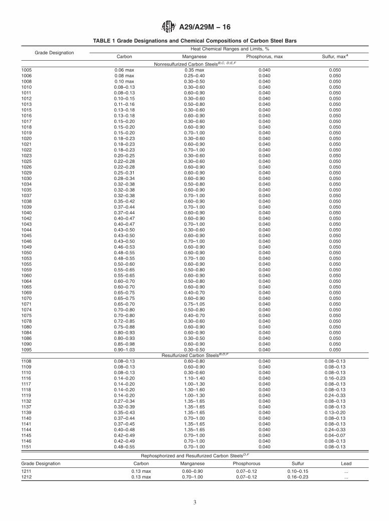
TABLE 1 Grade Designations and Chemical Compositions of Carbon Steel Bars
Grade DesignationHeat Chemical Ranges and Limits, %
Carbon Manganese Phosphorus, max Sulfur, maxA
Nonresulfurized Carbon SteelsB,C, D,E,F
1005 0.06 max 0.35 max 0.040 0.0501006 0.08 max 0.25–0.40 0.040 0.0501008 0.10 max 0.30–0.50 0.040 0.0501010 0.08–0.13 0.30–0.60 0.040 0.0501011 0.08–0.13 0.60–0.90 0.040 0.0501012 0.10–0.15 0.30–0.60 0.040 0.0501013 0.11–0.16 0.50–0.80 0.040 0.0501015 0.13–0.18 0.30–0.60 0.040 0.0501016 0.13–0.18 0.60–0.90 0.040 0.0501017 0.15–0.20 0.30–0.60 0.040 0.0501018 0.15–0.20 0.60–0.90 0.040 0.0501019 0.15–0.20 0.70–1.00 0.040 0.0501020 0.18–0.23 0.30–0.60 0.040 0.0501021 0.18–0.23 0.60–0.90 0.040 0.0501022 0.18–0.23 0.70–1.00 0.040 0.0501023 0.20–0.25 0.30–0.60 0.040 0.0501025 0.22–0.28 0.30–0.60 0.040 0.0501026 0.22–0.28 0.60–0.90 0.040 0.0501029 0.25–0.31 0.60–0.90 0.040 0.0501030 0.28–0.34 0.60–0.90 0.040 0.0501034 0.32–0.38 0.50–0.80 0.040 0.0501035 0.32–0.38 0.60–0.90 0.040 0.0501037 0.32–0.38 0.70–1.00 0.040 0.0501038 0.35–0.42 0.60–0.90 0.040 0.0501039 0.37–0.44 0.70–1.00 0.040 0.0501040 0.37–0.44 0.60–0.90 0.040 0.0501042 0.40–0.47 0.60–0.90 0.040 0.0501043 0.40–0.47 0.70–1.00 0.040 0.0501044 0.43–0.50 0.30–0.60 0.040 0.0501045 0.43–0.50 0.60–0.90 0.040 0.0501046 0.43–0.50 0.70–1.00 0.040 0.0501049 0.46–0.53 0.60–0.90 0.040 0.0501050 0.48–0.55 0.60–0.90 0.040 0.0501053 0.48–0.55 0.70–1.00 0.040 0.0501055 0.50–0.60 0.60–0.90 0.040 0.0501059 0.55–0.65 0.50–0.80 0.040 0.0501060 0.55–0.65 0.60–0.90 0.040 0.0501064 0.60–0.70 0.50–0.80 0.040 0.0501065 0.60–0.70 0.60–0.90 0.040 0.0501069 0.65–0.75 0.40–0.70 0.040 0.0501070 0.65–0.75 0.60–0.90 0.040 0.0501071 0.65–0.70 0.75–1.05 0.040 0.0501074 0.70–0.80 0.50–0.80 0.040 0.0501075 0.70–0.80 0.40–0.70 0.040 0.0501078 0.72–0.85 0.30–0.60 0.040 0.0501080 0.75–0.88 0.60–0.90 0.040 0.0501084 0.80–0.93 0.60–0.90 0.040 0.0501086 0.80–0.93 0.30–0.50 0.040 0.0501090 0.85–0.98 0.60–0.90 0.040 0.0501095 0.90–1.03 0.30–0.50 0.040 0.050
Resulfurized Carbon SteelsB,D,F
1108 0.08–0.13 0.60–0.80 0.040 0.08–0.131109 0.08–0.13 0.60–0.90 0.040 0.08–0.131110 0.08–0.13 0.30–0.60 0.040 0.08–0.131116 0.14–0.20 1.10–1.40 0.040 0.16–0.231117 0.14–0.20 1.00–1.30 0.040 0.08–0.131118 0.14–0.20 1.30–1.60 0.040 0.08–0.131119 0.14–0.20 1.00–1.30 0.040 0.24–0.331132 0.27–0.34 1.35–1.65 0.040 0.08–0.131137 0.32–0.39 1.35–1.65 0.040 0.08–0.131139 0.35–0.43 1.35–1.65 0.040 0.13–0.201140 0.37–0.44 0.70–1.00 0.040 0.08–0.131141 0.37–0.45 1.35–1.65 0.040 0.08–0.131144 0.40–0.48 1.35–1.65 0.040 0.24–0.331145 0.42–0.49 0.70–1.00 0.040 0.04–0.071146 0.42–0.49 0.70–1.00 0.040 0.08–0.131151 0.48–0.55 0.70–1.00 0.040 0.08–0.13
Rephosphorized and Resulfurized Carbon SteelsD,F
Grade Designation Carbon Manganese Phosphorous Sulfur Lead
1211 0.13 max 0.60–0.90 0.07–0.12 0.10–0.15 ...1212 0.13 max 0.70–1.00 0.07–0.12 0.16–0.23 ...
A29/A29M − 16
3
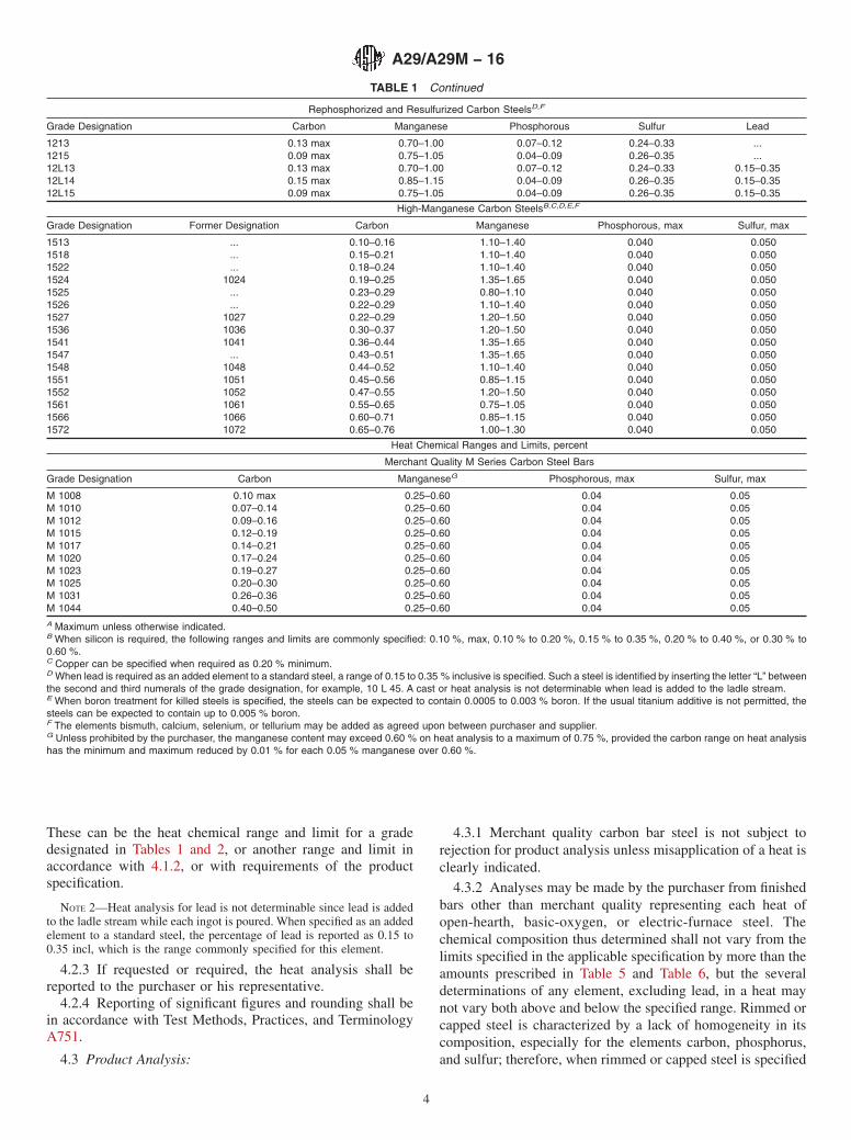
These can be the heat chemical range and limit for a gradedesignated in Tables 1 and 2, or another range and limit inaccordance with 4.1.2, or with requirements of the productspecification.
NOTE 2—Heat analysis for lead is not determinable since lead is addedto the ladle stream while each ingot is poured. When specified as an addedelement to a standard steel, the percentage of lead is reported as 0.15 to0.35 incl, which is the range commonly specified for this element.
4.2.3 If requested or required, the heat analysis shall bereported to the purchaser or his representative.
4.2.4 Reporting of significant figures and rounding shall bein accordance with Test Methods, Practices, and TerminologyA751.
4.3 Product Analysis:
4.3.1 Merchant quality carbon bar steel is not subject torejection for product analysis unless misapplication of a heat isclearly indicated.
4.3.2 Analyses may be made by the purchaser from finishedbars other than merchant quality representing each heat ofopen-hearth, basic-oxygen, or electric-furnace steel. Thechemical composition thus determined shall not vary from thelimits specified in the applicable specification by more than theamounts prescribed in Table 5 and Table 6, but the severaldeterminations of any element, excluding lead, in a heat maynot vary both above and below the specified range. Rimmed orcapped steel is characterized by a lack of homogeneity in itscomposition, especially for the elements carbon, phosphorus,and sulfur; therefore, when rimmed or capped steel is specified
TABLE 1 Continued
Rephosphorized and Resulfurized Carbon SteelsD,F
Grade Designation Carbon Manganese Phosphorous Sulfur Lead
1213 0.13 max 0.70–1.00 0.07–0.12 0.24–0.33 ...1215 0.09 max 0.75–1.05 0.04–0.09 0.26–0.35 ...12L13 0.13 max 0.70–1.00 0.07–0.12 0.24–0.33 0.15–0.3512L14 0.15 max 0.85–1.15 0.04–0.09 0.26–0.35 0.15–0.3512L15 0.09 max 0.75–1.05 0.04–0.09 0.26–0.35 0.15–0.35
High-Manganese Carbon SteelsB,C,D,E,F
Grade Designation Former Designation Carbon Manganese Phosphorous, max Sulfur, max
1513 ... 0.10–0.16 1.10–1.40 0.040 0.0501518 ... 0.15–0.21 1.10–1.40 0.040 0.0501522 ... 0.18–0.24 1.10–1.40 0.040 0.0501524 1024 0.19–0.25 1.35–1.65 0.040 0.0501525 ... 0.23–0.29 0.80–1.10 0.040 0.0501526 ... 0.22–0.29 1.10–1.40 0.040 0.0501527 1027 0.22–0.29 1.20–1.50 0.040 0.0501536 1036 0.30–0.37 1.20–1.50 0.040 0.0501541 1041 0.36–0.44 1.35–1.65 0.040 0.0501547 ... 0.43–0.51 1.35–1.65 0.040 0.0501548 1048 0.44–0.52 1.10–1.40 0.040 0.0501551 1051 0.45–0.56 0.85–1.15 0.040 0.0501552 1052 0.47–0.55 1.20–1.50 0.040 0.0501561 1061 0.55–0.65 0.75–1.05 0.040 0.0501566 1066 0.60–0.71 0.85–1.15 0.040 0.0501572 1072 0.65–0.76 1.00–1.30 0.040 0.050
Heat Chemical Ranges and Limits, percent
Merchant Quality M Series Carbon Steel Bars
Grade Designation Carbon ManganeseG Phosphorous, max Sulfur, max
M 1008 0.10 max 0.25–0.60 0.04 0.05M 1010 0.07–0.14 0.25–0.60 0.04 0.05M 1012 0.09–0.16 0.25–0.60 0.04 0.05M 1015 0.12–0.19 0.25–0.60 0.04 0.05M 1017 0.14–0.21 0.25–0.60 0.04 0.05M 1020 0.17–0.24 0.25–0.60 0.04 0.05M 1023 0.19–0.27 0.25–0.60 0.04 0.05M 1025 0.20–0.30 0.25–0.60 0.04 0.05M 1031 0.26–0.36 0.25–0.60 0.04 0.05M 1044 0.40–0.50 0.25–0.60 0.04 0.05A Maximum unless otherwise indicated.B When silicon is required, the following ranges and limits are commonly specified: 0.10 %, max, 0.10 % to 0.20 %, 0.15 % to 0.35 %, 0.20 % to 0.40 %, or 0.30 % to0.60 %.C Copper can be specified when required as 0.20 % minimum.D When lead is required as an added element to a standard steel, a range of 0.15 to 0.35 % inclusive is specified. Such a steel is identified by inserting the letter “L” betweenthe second and third numerals of the grade designation, for example, 10 L 45. A cast or heat analysis is not determinable when lead is added to the ladle stream.E When boron treatment for killed steels is specified, the steels can be expected to contain 0.0005 to 0.003 % boron. If the usual titanium additive is not permitted, thesteels can be expected to contain up to 0.005 % boron.F The elements bismuth, calcium, selenium, or tellurium may be added as agreed upon between purchaser and supplier.G Unless prohibited by the purchaser, the manganese content may exceed 0.60 % on heat analysis to a maximum of 0.75 %, provided the carbon range on heat analysishas the minimum and maximum reduced by 0.01 % for each 0.05 % manganese over 0.60 %.
A29/A29M − 16
4
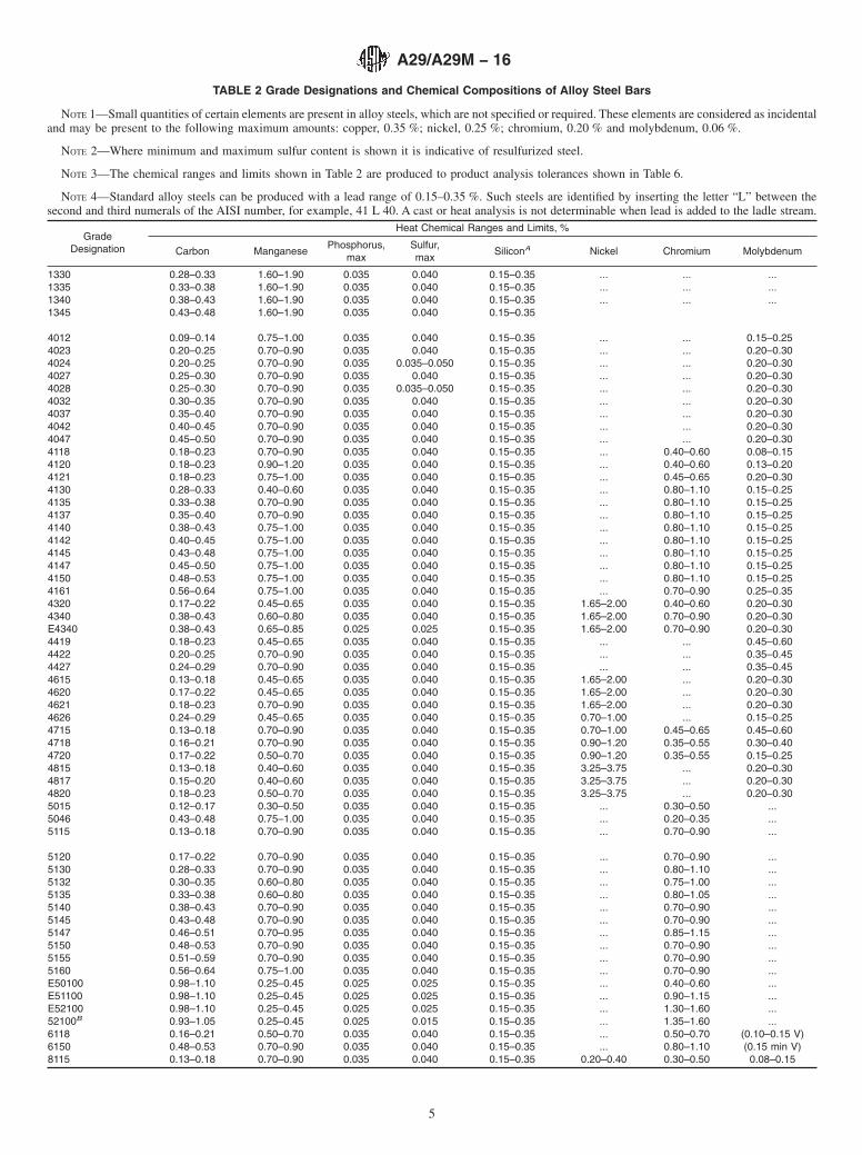
TABLE 2 Grade Designations and Chemical Compositions of Alloy Steel Bars
NOTE 1—Small quantities of certain elements are present in alloy steels, which are not specified or required. These elements are considered as incidentaland may be present to the following maximum amounts: copper, 0.35 %; nickel, 0.25 %; chromium, 0.20 % and molybdenum, 0.06 %.
NOTE 2—Where minimum and maximum sulfur content is shown it is indicative of resulfurized steel.
NOTE 3—The chemical ranges and limits shown in Table 2 are produced to product analysis tolerances shown in Table 6.
NOTE 4—Standard alloy steels can be produced with a lead range of 0.15–0.35 %. Such steels are identified by inserting the letter “L” between thesecond and third numerals of the AISI number, for example, 41 L 40. A cast or heat analysis is not determinable when lead is added to the ladle stream.
GradeDesignation
Heat Chemical Ranges and Limits, %
Carbon ManganesePhosphorus,
maxSulfur,max
SiliconA Nickel Chromium Molybdenum
1330 0.28–0.33 1.60–1.90 0.035 0.040 0.15–0.35 ... ... ...1335 0.33–0.38 1.60–1.90 0.035 0.040 0.15–0.35 ... ... ...1340 0.38–0.43 1.60–1.90 0.035 0.040 0.15–0.35 ... ... ...1345 0.43–0.48 1.60–1.90 0.035 0.040 0.15–0.35
4012 0.09–0.14 0.75–1.00 0.035 0.040 0.15–0.35 ... ... 0.15–0.254023 0.20–0.25 0.70–0.90 0.035 0.040 0.15–0.35 ... ... 0.20–0.304024 0.20–0.25 0.70–0.90 0.035 0.035–0.050 0.15–0.35 ... ... 0.20–0.304027 0.25–0.30 0.70–0.90 0.035 0.040 0.15–0.35 ... ... 0.20–0.304028 0.25–0.30 0.70–0.90 0.035 0.035–0.050 0.15–0.35 ... ... 0.20–0.304032 0.30–0.35 0.70–0.90 0.035 0.040 0.15–0.35 ... ... 0.20–0.304037 0.35–0.40 0.70–0.90 0.035 0.040 0.15–0.35 ... ... 0.20–0.304042 0.40–0.45 0.70–0.90 0.035 0.040 0.15–0.35 ... ... 0.20–0.304047 0.45–0.50 0.70–0.90 0.035 0.040 0.15–0.35 ... ... 0.20–0.304118 0.18–0.23 0.70–0.90 0.035 0.040 0.15–0.35 ... 0.40–0.60 0.08–0.154120 0.18–0.23 0.90–1.20 0.035 0.040 0.15–0.35 ... 0.40–0.60 0.13–0.204121 0.18–0.23 0.75–1.00 0.035 0.040 0.15–0.35 ... 0.45–0.65 0.20–0.304130 0.28–0.33 0.40–0.60 0.035 0.040 0.15–0.35 ... 0.80–1.10 0.15–0.254135 0.33–0.38 0.70–0.90 0.035 0.040 0.15–0.35 ... 0.80–1.10 0.15–0.254137 0.35–0.40 0.70–0.90 0.035 0.040 0.15–0.35 ... 0.80–1.10 0.15–0.254140 0.38–0.43 0.75–1.00 0.035 0.040 0.15–0.35 ... 0.80–1.10 0.15–0.254142 0.40–0.45 0.75–1.00 0.035 0.040 0.15–0.35 ... 0.80–1.10 0.15–0.254145 0.43–0.48 0.75–1.00 0.035 0.040 0.15–0.35 ... 0.80–1.10 0.15–0.254147 0.45–0.50 0.75–1.00 0.035 0.040 0.15–0.35 ... 0.80–1.10 0.15–0.254150 0.48–0.53 0.75–1.00 0.035 0.040 0.15–0.35 ... 0.80–1.10 0.15–0.254161 0.56–0.64 0.75–1.00 0.035 0.040 0.15–0.35 ... 0.70–0.90 0.25–0.354320 0.17–0.22 0.45–0.65 0.035 0.040 0.15–0.35 1.65–2.00 0.40–0.60 0.20–0.304340 0.38–0.43 0.60–0.80 0.035 0.040 0.15–0.35 1.65–2.00 0.70–0.90 0.20–0.30E4340 0.38–0.43 0.65–0.85 0.025 0.025 0.15–0.35 1.65–2.00 0.70–0.90 0.20–0.304419 0.18–0.23 0.45–0.65 0.035 0.040 0.15–0.35 ... ... 0.45–0.604422 0.20–0.25 0.70–0.90 0.035 0.040 0.15–0.35 ... ... 0.35–0.454427 0.24–0.29 0.70–0.90 0.035 0.040 0.15–0.35 ... ... 0.35–0.454615 0.13–0.18 0.45–0.65 0.035 0.040 0.15–0.35 1.65–2.00 ... 0.20–0.304620 0.17–0.22 0.45–0.65 0.035 0.040 0.15–0.35 1.65–2.00 ... 0.20–0.304621 0.18–0.23 0.70–0.90 0.035 0.040 0.15–0.35 1.65–2.00 ... 0.20–0.304626 0.24–0.29 0.45–0.65 0.035 0.040 0.15–0.35 0.70–1.00 ... 0.15–0.254715 0.13–0.18 0.70–0.90 0.035 0.040 0.15–0.35 0.70–1.00 0.45–0.65 0.45–0.604718 0.16–0.21 0.70–0.90 0.035 0.040 0.15–0.35 0.90–1.20 0.35–0.55 0.30–0.404720 0.17–0.22 0.50–0.70 0.035 0.040 0.15–0.35 0.90–1.20 0.35–0.55 0.15–0.254815 0.13–0.18 0.40–0.60 0.035 0.040 0.15–0.35 3.25–3.75 ... 0.20–0.304817 0.15–0.20 0.40–0.60 0.035 0.040 0.15–0.35 3.25–3.75 ... 0.20–0.304820 0.18–0.23 0.50–0.70 0.035 0.040 0.15–0.35 3.25–3.75 ... 0.20–0.305015 0.12–0.17 0.30–0.50 0.035 0.040 0.15–0.35 ... 0.30–0.50 ...5046 0.43–0.48 0.75–1.00 0.035 0.040 0.15–0.35 ... 0.20–0.35 ...5115 0.13–0.18 0.70–0.90 0.035 0.040 0.15–0.35 ... 0.70–0.90 ...
5120 0.17–0.22 0.70–0.90 0.035 0.040 0.15–0.35 ... 0.70–0.90 ...5130 0.28–0.33 0.70–0.90 0.035 0.040 0.15–0.35 ... 0.80–1.10 ...5132 0.30–0.35 0.60–0.80 0.035 0.040 0.15–0.35 ... 0.75–1.00 ...5135 0.33–0.38 0.60–0.80 0.035 0.040 0.15–0.35 ... 0.80–1.05 ...5140 0.38–0.43 0.70–0.90 0.035 0.040 0.15–0.35 ... 0.70–0.90 ...5145 0.43–0.48 0.70–0.90 0.035 0.040 0.15–0.35 ... 0.70–0.90 ...5147 0.46–0.51 0.70–0.95 0.035 0.040 0.15–0.35 ... 0.85–1.15 ...5150 0.48–0.53 0.70–0.90 0.035 0.040 0.15–0.35 ... 0.70–0.90 ...5155 0.51–0.59 0.70–0.90 0.035 0.040 0.15–0.35 ... 0.70–0.90 ...5160 0.56–0.64 0.75–1.00 0.035 0.040 0.15–0.35 ... 0.70–0.90 ...E50100 0.98–1.10 0.25–0.45 0.025 0.025 0.15–0.35 ... 0.40–0.60 ...E51100 0.98–1.10 0.25–0.45 0.025 0.025 0.15–0.35 ... 0.90–1.15 ...E52100 0.98–1.10 0.25–0.45 0.025 0.025 0.15–0.35 ... 1.30–1.60 ...52100B 0.93–1.05 0.25–0.45 0.025 0.015 0.15–0.35 ... 1.35–1.60 ...6118 0.16–0.21 0.50–0.70 0.035 0.040 0.15–0.35 ... 0.50–0.70 (0.10–0.15 V)6150 0.48–0.53 0.70–0.90 0.035 0.040 0.15–0.35 ... 0.80–1.10 (0.15 min V)8115 0.13–0.18 0.70–0.90 0.035 0.040 0.15–0.35 0.20–0.40 0.30–0.50 0.08–0.15
A29/A29M − 16
5
or required, the limitations for these elements shall not beapplicable. Because of the degree to which phosphorus andsulfur segregate, the limitations for these elements shall not beapplicable to rephosphorized or resulfurized steels.
4.3.3 Samples for product analysis shall be taken by one ofthe following methods:
4.3.3.1 Applicable to small sections whose cross-sectionalarea does not exceed 0.75 in.2 [500 mm2] such as rounds,squares, hexagons, and the like. Chips are taken by milling ormachining the full cross section of the piece. Drilling is not afeasible method for sampling sizes 0.75 in.2 and smaller.
4.3.3.2 Applicable to products where the width of the crosssection greatly exceeds the thickness, such as bar size shapesand light flat bars. Chips are taken by drilling entirely throughthe steel at a point midway between the edge and the middle ofthe section, or by milling or machining the entire cross section.
4.3.3.3 Applicable to large rounds, squares semifinished,etc. Chips are taken at any point midway between the outsideand the center of the piece by drilling parallel to the axis or bymilling or machining the full cross section. In cases wherethese methods are not practicable, the piece may be drilled onthe side, but chips are not taken until they represent the portionmidway between the outside and the center.
4.3.3.4 When the steel is subject to tension testrequirements, the tension test specimen can also be used for
product analysis. In that case, chips for product analysis can betaken by drilling entirely through the tension test specimens orby the method described in 4.3.3.1.
4.3.4 When chips are taken by drilling, the diameter of thedrill used shall conform to the following:
Area of Sample Cross Section,in.2 [cm2]
Approximate Drill Diameter,in. [mm]
16 [100] or less 1⁄2 [12.5]Over 16 [100] 1 [25.0]
4.3.5 The minimum number of samples to be taken frommaterial representing the same heat or lot before rejection bythe purchaser shall be as follows:
Minimum Numberof Samples
15 tons [15 Mg] and under 4Over 15 tons [15 Mg] 6
4.3.6 In case the number of pieces in a heat is less than thenumber of samples required, one sample from each piece shallbe considered sufficient.
4.3.7 In the event that product analysis determinations areoutside the permissible limits as prescribed in 4.3.2, additionalsamples shall be analyzed and the acceptability of the heatnegotiated between the purchaser and the producer.
4.4 Referee Analysis—In case a referee analysis is requiredand agreed upon to resolve a dispute concerning the results of
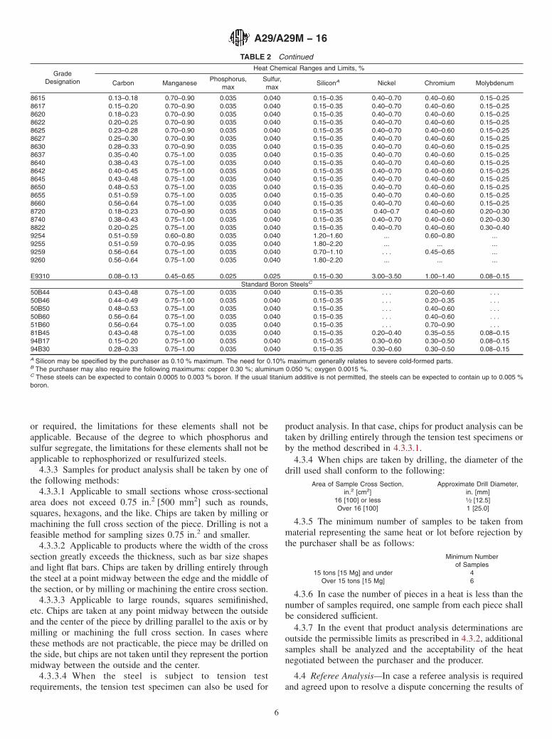
TABLE 2 Continued
GradeDesignation
Heat Chemical Ranges and Limits, %
Carbon ManganesePhosphorus,
maxSulfur,max
SiliconA Nickel Chromium Molybdenum
8615 0.13–0.18 0.70–0.90 0.035 0.040 0.15–0.35 0.40–0.70 0.40–0.60 0.15–0.258617 0.15–0.20 0.70–0.90 0.035 0.040 0.15–0.35 0.40–0.70 0.40–0.60 0.15–0.258620 0.18–0.23 0.70–0.90 0.035 0.040 0.15–0.35 0.40–0.70 0.40–0.60 0.15–0.258622 0.20–0.25 0.70–0.90 0.035 0.040 0.15–0.35 0.40–0.70 0.40–0.60 0.15–0.258625 0.23–0.28 0.70–0.90 0.035 0.040 0.15–0.35 0.40–0.70 0.40–0.60 0.15–0.258627 0.25–0.30 0.70–0.90 0.035 0.040 0.15–0.35 0.40–0.70 0.40–0.60 0.15–0.258630 0.28–0.33 0.70–0.90 0.035 0.040 0.15–0.35 0.40–0.70 0.40–0.60 0.15–0.258637 0.35–0.40 0.75–1.00 0.035 0.040 0.15–0.35 0.40–0.70 0.40–0.60 0.15–0.258640 0.38–0.43 0.75–1.00 0.035 0.040 0.15–0.35 0.40–0.70 0.40–0.60 0.15–0.258642 0.40–0.45 0.75–1.00 0.035 0.040 0.15–0.35 0.40–0.70 0.40–0.60 0.15–0.258645 0.43–0.48 0.75–1.00 0.035 0.040 0.15–0.35 0.40–0.70 0.40–0.60 0.15–0.258650 0.48–0.53 0.75–1.00 0.035 0.040 0.15–0.35 0.40–0.70 0.40–0.60 0.15–0.258655 0.51–0.59 0.75–1.00 0.035 0.040 0.15–0.35 0.40–0.70 0.40–0.60 0.15–0.258660 0.56–0.64 0.75–1.00 0.035 0.040 0.15–0.35 0.40–0.70 0.40–0.60 0.15–0.258720 0.18–0.23 0.70–0.90 0.035 0.040 0.15–0.35 0.40–0.7 0.40–0.60 0.20–0.308740 0.38–0.43 0.75–1.00 0.035 0.040 0.15–0.35 0.40–0.70 0.40–0.60 0.20–0.308822 0.20–0.25 0.75–1.00 0.035 0.040 0.15–0.35 0.40–0.70 0.40–0.60 0.30–0.409254 0.51–0.59 0.60–0.80 0.035 0.040 1.20–1.60 ... 0.60–0.80 ...9255 0.51–0.59 0.70–0.95 0.035 0.040 1.80–2.20 ... ... ...9259 0.56–0.64 0.75–1.00 0.035 0.040 0.70–1.10 . . . 0.45–0.65 ...9260 0.56–0.64 0.75–1.00 0.035 0.040 1.80–2.20 ... ... ...
E9310 0.08–0.13 0.45–0.65 0.025 0.025 0.15–0.30 3.00–3.50 1.00–1.40 0.08–0.15Standard Boron SteelsC
50B44 0.43–0.48 0.75–1.00 0.035 0.040 0.15–0.35 . . . 0.20–0.60 . . .50B46 0.44–0.49 0.75–1.00 0.035 0.040 0.15–0.35 . . . 0.20–0.35 . . .50B50 0.48–0.53 0.75–1.00 0.035 0.040 0.15–0.35 . . . 0.40–0.60 . . .50B60 0.56–0.64 0.75–1.00 0.035 0.040 0.15–0.35 . . . 0.40–0.60 . . .51B60 0.56–0.64 0.75–1.00 0.035 0.040 0.15–0.35 . . . 0.70–0.90 . . .81B45 0.43–0.48 0.75–1.00 0.035 0.040 0.15–0.35 0.20–0.40 0.35–0.55 0.08–0.1594B17 0.15–0.20 0.75–1.00 0.035 0.040 0.15–0.35 0.30–0.60 0.30–0.50 0.08–0.1594B30 0.28–0.33 0.75–1.00 0.035 0.040 0.15–0.35 0.30–0.60 0.30–0.50 0.08–0.15A Silicon may be specified by the purchaser as 0.10 % maximum. The need for 0.10% maximum generally relates to severe cold-formed parts.B The purchaser may also require the following maximums: copper 0.30 %; aluminum 0.050 %; oxygen 0.0015 %.C These steels can be expected to contain 0.0005 to 0.003 % boron. If the usual titanium additive is not permitted, the steels can be expected to contain up to 0.005 %boron.
A29/A29M − 16
6

a chemical analysis, the referee analysis shall be performed inaccordance with the latest issue of Test Methods, Practices, andTerminology A751, unless otherwise agreed upon between themanufacturer and the purchaser.
5. Grain Size Requirement
5.1 Austenitic Grain Size—All requirements for austeniticgrain size control in Section 5 refer to the size of the austenitegrain which forms during a subsequent bar reheating operationat or above the recrystallization temperature. These require-ments do not apply to, nor do they in any way control, the prioraustenite grain size or the ferrite grain size of the bar in theas-rolled condition.
5.1.1 When a coarse austenitic grain size is specified, thesteel shall have a grain size number of 1 to 5 exclusive asdetermined in accordance with Test Methods E112. Confor-mance to this grain size of 70 % of the grains in the areaexamined shall constitute the basis of acceptance. One test perheat shall be made.
5.1.2 When a fine austenitic grain size is specified, the steelshall have a grain size number of 5 or higher as determined inaccordance with Test Methods E112. Conformance to thisgrain size of 70 % of the area examined shall constitute thebasis of acceptance. One test per heat shall be made unless theprovisions of 5.1.2.1 or 5.1.2.2 are exercised.
5.1.2.1 When aluminum is used as the grain refiningelement, the fine austenitic grain size requirement shall bedeemed to be fulfilled if, on heat analysis, the aluminumcontent is not less than 0.020 % total aluminum or, alternately,0.015 % acid soluble aluminum. The aluminum content shallbe reported. The grain size test specified in 5.1.2 shall be thereferee test.
5.1.2.2 By agreement between purchaser and supplier, co-lumbium7 or vanadium, or both, may be used for grain refininginstead of or with aluminum. When columbium or vanadium isused as a grain refining element, the fine austenitic grain sizerequirement shall be deemed to be fulfilled if, on heat analysis,the columbium or vanadium content is as follows (the contentof the elements shall be reported with the heat analysis):
Steels having 0.25 % carbon or less:Cb 0.025 minV 0.05 min
Steels having over 0.25 % carbon:Cb 0.015 minV 0.02 min
The maximum contents shall be:Cb 0.05 maxV 0.08 max
Cb + V 0.06 max
When V is specified in the material specification or purchaseorder, the V and Cb+V maximums do not apply.
5.1.2.3 When provisions of 5.1.2.1 or 5.1.2.2 are exercised,a grain size test is not required unless specified by thepurchaser. Unless otherwise specified, fine austenitic grain sizeshall be certified using the analysis of grain refining element(s).
5.1.2.4 Referee Test—In the event that the chemical analysisof columbium7 or vanadium does not meet the requirements of5.1.2.2, the grain size test shown in 5.1.2 shall be the refereetest unless an alternative test method is agreed upon betweenthe manufacturer and the purchaser.
6. Mechanical Property Requirements
6.1 Test Specimens:6.1.1 Selection—Test specimens shall be selected in accor-
dance with the requirements of the applicable product specifi-cation or in accordance with Supplement I of the latest issue ofTest Methods and Definitions A370, in the sequence named.
7 Columbium (Cb) and Niobium (Nb) are alternate names for element 41 in thePeriodic Table of the Elements.
TABLE 3 Heat Analysis Chemical Ranges and Limits of CarbonSteel Bars
ElementChemical Ranges and Limits, %
When Maximum of SpecifiedElements is:
RangeLowest
Maximum
CarbonA ... ... 0.06to 0.12, incl ... ...over 0.12 to 0.25, incl 0.05 ...over 0.25 to 0.40, incl 0.06 ...over 0.40 to 0.55, incl 0.07 ...over 0.55 to 0.80, incl 0.10 ...over 0.80 0.13 ...
Manganese ... ... 0.35to 0.40, incl 0.15 ...over 0.40 to 0.50, incl 0.20 ...over 0.50 to 1.65, incl 0.30 ...
Phosphorus to 0.040, incl ... 0.040B
over 0.040 to 0.08, incl 0.03 ...over 0.08 to 0.13, incl 0.05 ...
Sulfur to 0.050, incl ... 0.050B
over 0.050 to 0.09, incl 0.03 ...over 0.09 to 0.15, incl 0.05 ...over 0.15 to 0.23, incl 0.07 ...over 0.23 to 0.50, incl 0.09 ...
SiliconC ... ... 0.10to 0.10, incl ... ...over 0.10 to 0.15, incl 0.08 ...over 0.15 to 0.20, incl 0.10 ...over 0.20 to 0.30, incl 0.15 ...over 0.30 to 0.60, incl 0.20 ...
Copper When copper is required 0.20min is generally used
LeadD When lead is required, a rangeof 0.15 to 0.35 is specified
BismuthE
CalciumE
SeleniumE
TelluriumE
A The carbon ranges shown in the column headed “Range” apply when thespecified maximum limit for manganese does not exceed 1.10 %. When themaximum manganese limit exceeds 1.10 %, add 0.01 to the carbon ranges shownabove.B For steels produced in merchant quality the phosphorus maximum is 0.04 % andthe sulfur maximum is 0.05 %.C It is not common practice to produce a rephosphorized and resulfurized carbonsteel to specified limits for silicon because of its adverse effect on machinability.D A cast or heat analysis is not determinable when lead is added to the ladlestream.E Element specification range as agreed upon between purchaser and supplier.
A29/A29M − 16
7

TABLE 4 Heat Analysis Chemical Ranges and Limits of Alloy Steel Bars
NOTE 1—Boron steels can be expected to have 0.0005 % minimum boron content.
NOTE 2—Alloy steels can be produced with a lead range of 0.15–0.35 %. A cast or heat analysis is not determinable when lead is added to the ladlestream.
ElementChemical Ranges and Limits, %
When Maximum of SpecifiedElement is:
Open-Hearth or Basic-OxygenSteel
Electric Furnace Steel Maximum Limit, %A
Carbon To 0.55, incl 0.05 0.05Over 0.55–0.70, incl 0.08 0.07Over 0.70 to 0.80, incl 0.10 0.09Over 0.80–0.95, incl 0.12 0.11Over 0.95–1.35, incl 0.13 0.12
Manganese To 0.60, incl 0.20 0.15Over 0.60–0.90, incl 0.20 0.20Over 0.90–1.05, incl 0.25 0.25Over 1.05–1.90, incl 0.30 0.30Over 1.90–2.10, incl 0.40 0.35
Phosphorus Basic open-hearth or basic-oxygen steel 0.035
Acid open-hearth steel 0.050Basic electric-furnace steel 0.025Acid electric-furnace steel 0.050
Sulfur To 0.050, incl 0.015 0.015Over 0.050–0.07, incl 0.02 0.02Over 0.07–0.10, incl 0.04 0.04Over 0.10–0.14, incl 0.05 0.05Basic open-hearth or basic-
oxygen steel 0.040Acid open-hearth steel 0.050Basic electric-furnace steel 0.025Acid electric-furnace steel 0.050
Silicon To 0.20, incl 0.08 0.08Over 0.20–0.30, incl 0.15 0.15Over 0.30–0.60, incl 0.20 0.20Over 0.60–1.00, incl 0.30 0.30Over 1.00–2.20, incl 0.40 0.35Acid steelsB
Nickel To 0.50, incl 0.20 0.20Over 0.50–1.50, incl 0.30 0.30Over 1.50–2.00, incl 0.35 0.35Over 2.00–3.00, incl 0.40 0.40Over 3.00–5.30, incl 0.50 0.50Over 5.30–10.00, incl 1.00 1.00
Chromium To 0.40, incl 0.15 0.15Over 0.40–0.90, incl 0.20 0.20Over 0.90–1.05, incl 0.25 0.25Over 1.05–1.60, incl 0.30 0.30Over 1.60–1.75, incl C 0.35Over 1.75–2.10, incl C 0.40Over 2.10–3.99, incl C 0.50
Molybdenum To 0.10, incl 0.05 0.05Over 0.10–0.20, incl 0.07 0.07Over 0.20–0.50, incl 0.10 0.10Over 0.50–0.80, incl 0.15 0.15Over 0.80–1.15, incl 0.20 0.20
Tungsten To 0.50, incl 0.20 0.20Over 0.50–1.00, incl 0.30 0.30Over 1.00–2.00, incl 0.50 0.50Over 2.00–4.00, incl 0.60 0.60
Vanadium To 0.25, incl 0.05 0.05Over 0.25–0.50, incl 0.10 0.10
Aluminum Up to 0.10, incl 0.05 0.05Over 0.10–0.20, incl 0.10 0.10Over 0.20–0.30, incl 0.15 0.15Over 0.30–0.80, incl 0.25 0.25Over 0.80–1.30, incl 0.35 0.35Over 1.30–1.80, incl 0.45 0.45
Copper To 0.60, incl 0.20 0.20Over 0.60–1.50, incl 0.30 0.30Over 1.50–2.00, incl 0.35 0.35
A Applies to only nonrephosphorized and nonresulfurized steels.B Minimum silicon limit for acid open-hearth or acid electric-furnace alloy steels is 0.15 %.C Not normally produced in open-hearth.
A29/A29M − 16
8
6.1.2 Preparation—Unless otherwise specified in the appli-cable product specification, test specimens shall be prepared inaccordance with the latest issue of Test Methods and Defini-tions A370, and especially Supplement I thereof.
6.2 Methods of Mechanical Testing—All mechanical testsshall be conducted in accordance with the latest issue of TestMethods and Definitions A370, and especially Supplement Ithereof, on steel bar products.
6.3 Retests:6.3.1 If any test specimen shows defective machining or
develops flaws, the specimen may be discarded and anothersubstituted.
6.3.2 If the percentage elongation of any tension specimenis less than that specified and any part of the fracture is morethan 3⁄4 in. [20 mm] from the center of a 2-in. [50-mm]specimen, or is outside the middle half of the gage length of an8-in. [200-mm] specimen as indicated by scribe scratchesmarked on the specimen before testing, a retest shall beallowed.
6.3.3 For “as-wrought” material, if the results for anyoriginal tension specimen are within 2000 psi [14 MPa] of therequired tensile strength, within 1000 psi [7 MPa] of therequired yield point, or within 2 % of the required elongation,retesting shall be permitted. If the original testing required onlyone test, the retest shall consist of two random tests from theheat or lot involved. If the original testing required two tests ofwhich one failed by the amounts listed in this paragraph, theretest shall be made on one random test from the heat or lot. Ifthe results on the retest specimen or specimens meet thespecified requirements, the heat or test lot will be accepted. Ifthe results of one retest specimen do not meet the specifiedrequirements, the material is subject to rejection.
6.3.4 For thermally treated bars, if the results of the me-chanical tests do not conform to the requirements specified,two more tests may be selected for each bar failing, and eachof these retests shall conform to the requirements of theproduct specification.
6.3.5 If a bend specimen fails, due to conditions of bendingmore severe than required by the specification, a retest shall bepermitted from the heat or test lot involved for which onerandom specimen for each original specimen showing failureshall be used. If the results on the retest specimen meet therequirements of the specification, the heat or test lot will beaccepted.
7. Dimensions, Mass, and Permissible Variations
7.1 Hot-Wrought Bars—The permissible variations for di-mensions of hot-wrought carbon and alloy steel bars shall notexceed the applicable limits stated in Annex A1 for inch-poundvalues and Annex A2 for metric values.
8. Workmanship, Finish, and Appearance
8.1 The material shall be free of injurious defects and shallhave a workmanlike finish.
9. Rework and Retreatment
9.1 For thermally treated bars only, the manufacturer mayretreat a lot one or more times, and retests shall be made in thesame manner as the original tests. Each such retest shallconform to the requirements specified.
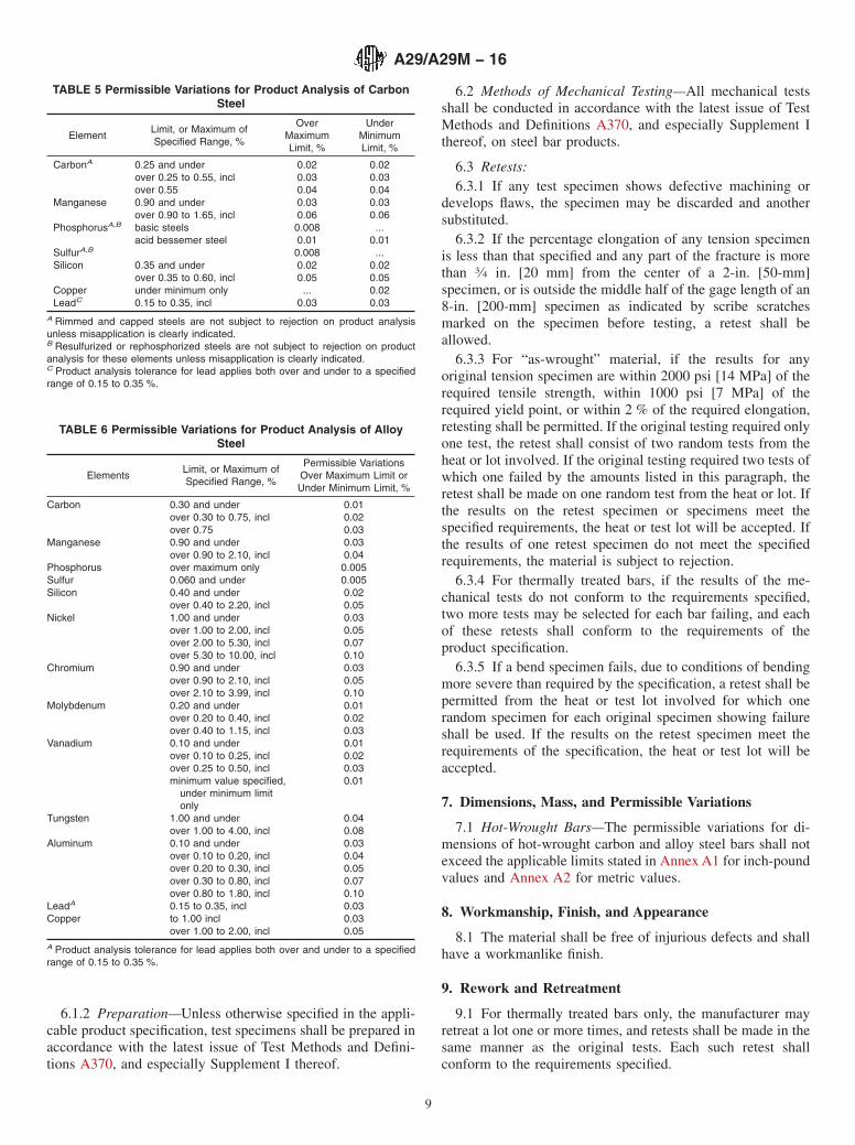
TABLE 5 Permissible Variations for Product Analysis of CarbonSteel
ElementLimit, or Maximum ofSpecified Range, %
OverMaximumLimit, %
UnderMinimumLimit, %
CarbonA 0.25 and under 0.02 0.02over 0.25 to 0.55, incl 0.03 0.03over 0.55 0.04 0.04
Manganese 0.90 and under 0.03 0.03over 0.90 to 1.65, incl 0.06 0.06
PhosphorusA,B basic steels 0.008 ...acid bessemer steel 0.01 0.01
SulfurA,B 0.008 ...Silicon 0.35 and under 0.02 0.02
over 0.35 to 0.60, incl 0.05 0.05Copper under minimum only ... 0.02LeadC 0.15 to 0.35, incl 0.03 0.03
A Rimmed and capped steels are not subject to rejection on product analysisunless misapplication is clearly indicated.B Resulfurized or rephosphorized steels are not subject to rejection on productanalysis for these elements unless misapplication is clearly indicated.C Product analysis tolerance for lead applies both over and under to a specifiedrange of 0.15 to 0.35 %.
TABLE 6 Permissible Variations for Product Analysis of AlloySteel
ElementsLimit, or Maximum ofSpecified Range, %
Permissible VariationsOver Maximum Limit orUnder Minimum Limit, %
Carbon 0.30 and under 0.01over 0.30 to 0.75, incl 0.02over 0.75 0.03
Manganese 0.90 and under 0.03over 0.90 to 2.10, incl 0.04
Phosphorus over maximum only 0.005Sulfur 0.060 and under 0.005Silicon 0.40 and under 0.02
over 0.40 to 2.20, incl 0.05Nickel 1.00 and under 0.03
over 1.00 to 2.00, incl 0.05over 2.00 to 5.30, incl 0.07over 5.30 to 10.00, incl 0.10
Chromium 0.90 and under 0.03over 0.90 to 2.10, incl 0.05over 2.10 to 3.99, incl 0.10
Molybdenum 0.20 and under 0.01over 0.20 to 0.40, incl 0.02over 0.40 to 1.15, incl 0.03
Vanadium 0.10 and under 0.01over 0.10 to 0.25, incl 0.02over 0.25 to 0.50, incl 0.03minimum value specified,
under minimum limitonly
0.01
Tungsten 1.00 and under 0.04over 1.00 to 4.00, incl 0.08
Aluminum 0.10 and under 0.03over 0.10 to 0.20, incl 0.04over 0.20 to 0.30, incl 0.05over 0.30 to 0.80, incl 0.07over 0.80 to 1.80, incl 0.10
LeadA 0.15 to 0.35, incl 0.03Copper to 1.00 incl 0.03
over 1.00 to 2.00, incl 0.05A Product analysis tolerance for lead applies both over and under to a specifiedrange of 0.15 to 0.35 %.
A29/A29M − 16
9
10. Inspection
10.1 The inspector representing the purchaser shall haveentry, at all times while work on the contract of the purchaseris being performed, to all parts of the manufacturer’s worksthat concern the manufacture of the material ordered. Themanufacturer shall afford the inspector all reasonable facilitiesto satisfy him that the material is being furnished in accordancewith this specification. All tests (except product analysis) andinspection shall be made at the place of manufacture prior toshipment, unless otherwise specified, and shall be so conductedas not to interfere unnecessarily with the operation of theworks.
10.2 All required tests and inspection shall be made by themanufacturer prior to shipment.
11. Rejection
11.1 Unless otherwise specified, any rejection because ofnoncompliance to the requirements of the specification shall bereported by the purchaser to the manufacturer within 30working days after receipt of samples.
11.2 Material that shows imperfections capable of adverselyaffecting processibility subsequent to its acceptance at thepurchaser’s works will be rejected, and the manufacturer shallbe notified.
12. Rehearing
12.1 Samples that represent rejected material shall be pre-served for two weeks from the date rejection is reported to themanufacturer. In case of dissatisfaction with the results of thetests, the manufacturer may make claim for a rehearing withinthat time.
13. Product Marking
13.1 Civilian Procurement—Bars of all sizes, when loadedfor shipment, shall be properly identified with the name or
brand of manufacturer, purchaser’s name and order number,the ASTM designation (year date is not required), gradenumber where appropriate, size and length, weight of lift, andthe heat number for identification. Unless otherwise specified,the method of marking is at the manufacturer’s option and maybe made by hot stamping, cold stamping, painting, or markingtags attached to the lifts of bars.
13.1.1 Bar code marking may be used as an auxiliarymethod of identification. Such bar-code markings shall be ofthe 3-of-9 type and shall conform to AIAG B1. When barcodedtags are used, they shall conform to AIAG B5.
13.2 Government Procurement:13.2.1 Marking for shipment shall be in accordance with the
requirements specified in the contract or order and shall be inaccordance with MIL-STD-163 for military agencies and inaccordance with Fed. Std. No. 123 for civil agencies.
13.2.2 For government procurement by the Defense SupplyAgency, the bars shall be continuously marked for identifica-tion in accordance with Fed. Std. No. 183.
14. Packaging
14.1 Civilian Procurement—Unless otherwise specified, thebars shall be packaged and loaded in accordance with GuideA700.
14.2 Government Procurement—MIL-STD-163 shall applywhen packaging is specified in the contract or order, or whenLevel A for preservation, packaging, and packing is specifiedfor direct procurement by or direct shipment to the govern-ment.
15. Keywords
15.1 alloy steel bars; carbon steel bars; cold finished steelbars; general delivery requirements; hot wrought steel bars;steel bars
SUPPLEMENTARY REQUIREMENTS
The following supplementary requirements shall apply only when specified by the purchaser in thecontract or order.
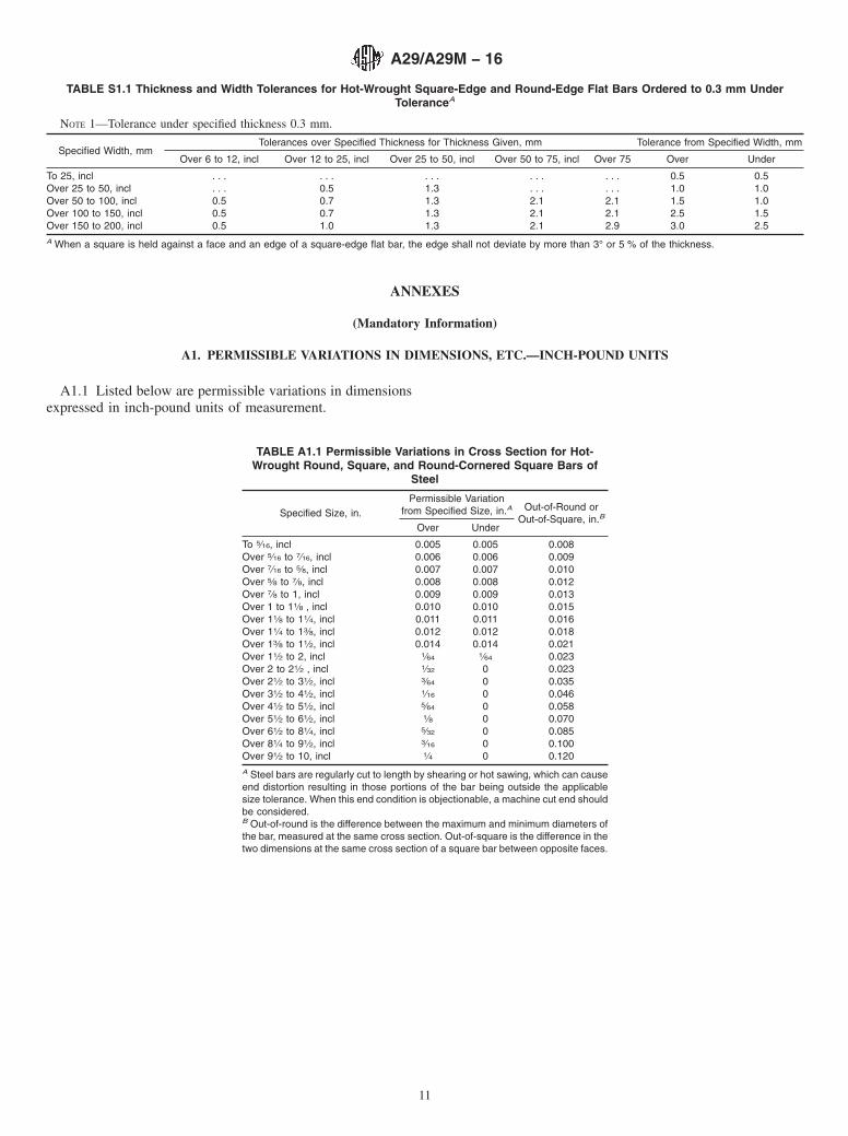
S1. Flat Bar Thickness Tolerances
S1.1 When flat bars are specified in metric units to athickness under tolerance of 0.3 mm, the thickness tolerance ofTable S1.1 shall apply.
A29/A29M − 16
10
ANNEXES
(Mandatory Information)
A1. PERMISSIBLE VARIATIONS IN DIMENSIONS, ETC.—INCH-POUND UNITS
A1.1 Listed below are permissible variations in dimensionsexpressed in inch-pound units of measurement.
TABLE S1.1 Thickness and Width Tolerances for Hot-Wrought Square-Edge and Round-Edge Flat Bars Ordered to 0.3 mm UnderToleranceA
NOTE 1—Tolerance under specified thickness 0.3 mm.
Specified Width, mmTolerances over Specified Thickness for Thickness Given, mm Tolerance from Specified Width, mm
Over 6 to 12, incl Over 12 to 25, incl Over 25 to 50, incl Over 50 to 75, incl Over 75 Over Under
To 25, incl . . . . . . . . . . . . . . . 0.5 0.5Over 25 to 50, incl . . . 0.5 1.3 . . . . . . 1.0 1.0Over 50 to 100, incl 0.5 0.7 1.3 2.1 2.1 1.5 1.0Over 100 to 150, incl 0.5 0.7 1.3 2.1 2.1 2.5 1.5Over 150 to 200, incl 0.5 1.0 1.3 2.1 2.9 3.0 2.5A When a square is held against a face and an edge of a square-edge flat bar, the edge shall not deviate by more than 3° or 5 % of the thickness.
TABLE A1.1 Permissible Variations in Cross Section for Hot-Wrought Round, Square, and Round-Cornered Square Bars of
Steel
Specified Size, in.Permissible Variation
from Specified Size, in.A Out-of-Round orOut-of-Square, in.B
Over Under
To 5⁄16, incl 0.005 0.005 0.008Over 5⁄16 to 7⁄16, incl 0.006 0.006 0.009Over 7⁄16 to 5⁄8, incl 0.007 0.007 0.010Over 5⁄8 to 7⁄8, incl 0.008 0.008 0.012Over 7⁄8 to 1, incl 0.009 0.009 0.013Over 1 to 11⁄8 , incl 0.010 0.010 0.015Over 11⁄8 to 11⁄4, incl 0.011 0.011 0.016Over 11⁄4 to 13⁄8, incl 0.012 0.012 0.018Over 13⁄8 to 11⁄2, incl 0.014 0.014 0.021Over 11⁄2 to 2, incl 1⁄64 1⁄64 0.023Over 2 to 21⁄2 , incl 1⁄32 0 0.023Over 21⁄2 to 31⁄2, incl 3⁄64 0 0.035Over 31⁄2 to 41⁄2, incl 1⁄16 0 0.046Over 41⁄2 to 51⁄2, incl 5⁄64 0 0.058Over 51⁄2 to 61⁄2, incl 1⁄8 0 0.070Over 61⁄2 to 81⁄4, incl 5⁄32 0 0.085Over 81⁄4 to 91⁄2, incl 3⁄16 0 0.100Over 91⁄2 to 10, incl 1⁄4 0 0.120A Steel bars are regularly cut to length by shearing or hot sawing, which can causeend distortion resulting in those portions of the bar being outside the applicablesize tolerance. When this end condition is objectionable, a machine cut end shouldbe considered.B Out-of-round is the difference between the maximum and minimum diameters ofthe bar, measured at the same cross section. Out-of-square is the difference in thetwo dimensions at the same cross section of a square bar between opposite faces.
A29/A29M − 16
11
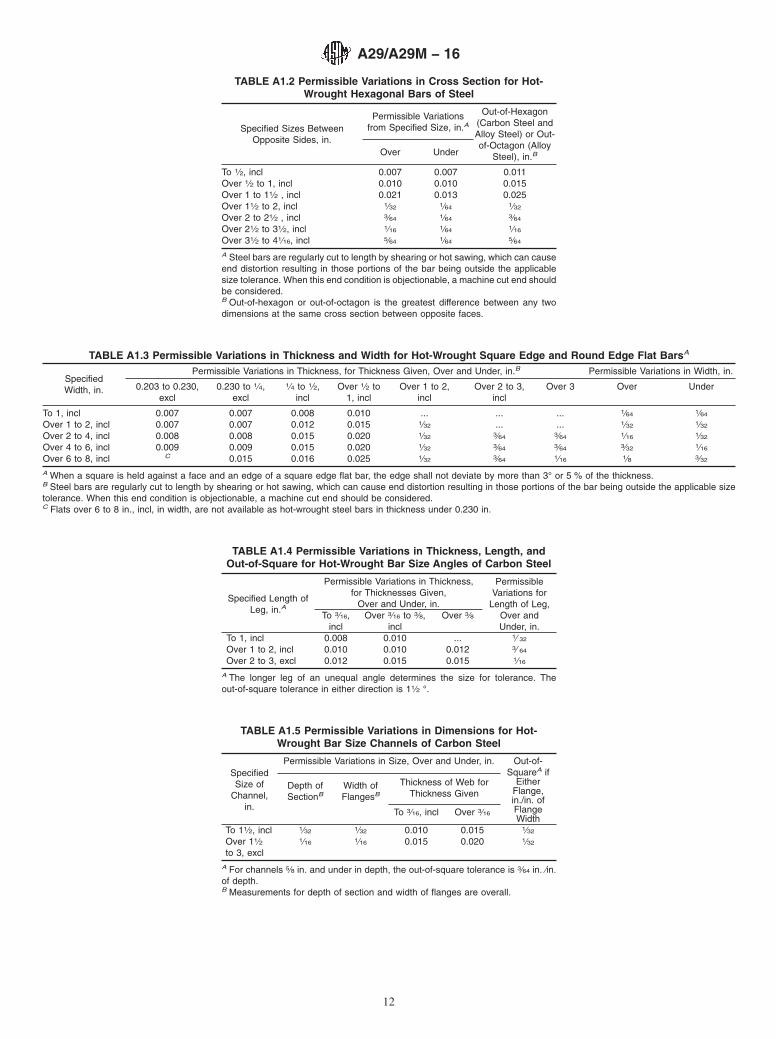
TABLE A1.2 Permissible Variations in Cross Section for Hot-Wrought Hexagonal Bars of Steel
Specified Sizes BetweenOpposite Sides, in.
Permissible Variationsfrom Specified Size, in.A
Out-of-Hexagon(Carbon Steel andAlloy Steel) or Out-of-Octagon (Alloy
Steel), in.BOver Under
To 1⁄2, incl 0.007 0.007 0.011Over 1⁄2 to 1, incl 0.010 0.010 0.015Over 1 to 11⁄2 , incl 0.021 0.013 0.025Over 11⁄2 to 2, incl 1⁄32 1⁄64 1⁄32
Over 2 to 21⁄2 , incl 3⁄64 1⁄64 3⁄64
Over 21⁄2 to 31⁄2, incl 1⁄16 1⁄64 1⁄16
Over 31⁄2 to 41⁄16, incl 5⁄64 1⁄64 5⁄64
A Steel bars are regularly cut to length by shearing or hot sawing, which can causeend distortion resulting in those portions of the bar being outside the applicablesize tolerance. When this end condition is objectionable, a machine cut end shouldbe considered.B Out-of-hexagon or out-of-octagon is the greatest difference between any twodimensions at the same cross section between opposite faces.
TABLE A1.3 Permissible Variations in Thickness and Width for Hot-Wrought Square Edge and Round Edge Flat BarsA
SpecifiedWidth, in.
Permissible Variations in Thickness, for Thickness Given, Over and Under, in.B Permissible Variations in Width, in.
0.203 to 0.230,excl
0.230 to 1⁄4,excl
1⁄4 to 1⁄2,incl
Over 1⁄2 to1, incl
Over 1 to 2,incl
Over 2 to 3,incl
Over 3 Over Under
To 1, incl 0.007 0.007 0.008 0.010 ... ... ... 1⁄64 1⁄64
Over 1 to 2, incl 0.007 0.007 0.012 0.015 1⁄32 ... ... 1⁄32 1⁄32
Over 2 to 4, incl 0.008 0.008 0.015 0.020 1⁄32 3⁄64 3⁄64 1⁄16 1⁄32
Over 4 to 6, incl 0.009 0.009 0.015 0.020 1⁄32 3⁄64 3⁄64 3⁄32 1⁄16
Over 6 to 8, incl C 0.015 0.016 0.025 1⁄32 3⁄64 1⁄16 1⁄8 3⁄32
A When a square is held against a face and an edge of a square edge flat bar, the edge shall not deviate by more than 3° or 5 % of the thickness.B Steel bars are regularly cut to length by shearing or hot sawing, which can cause end distortion resulting in those portions of the bar being outside the applicable sizetolerance. When this end condition is objectionable, a machine cut end should be considered.C Flats over 6 to 8 in., incl, in width, are not available as hot-wrought steel bars in thickness under 0.230 in.
TABLE A1.4 Permissible Variations in Thickness, Length, andOut-of-Square for Hot-Wrought Bar Size Angles of Carbon Steel
Specified Length ofLeg, in.A
Permissible Variations in Thickness,for Thicknesses Given,
Over and Under, in.
PermissibleVariations for
Length of Leg,Over andUnder, in.
To 3⁄16,incl
Over 3⁄16 to 3⁄8,incl
Over 3⁄8
To 1, incl 0.008 0.010 ... 1⁄ 32
Over 1 to 2, incl 0.010 0.010 0.012 3⁄ 64
Over 2 to 3, excl 0.012 0.015 0.015 1⁄16
A The longer leg of an unequal angle determines the size for tolerance. Theout-of-square tolerance in either direction is 11⁄2 °.
TABLE A1.5 Permissible Variations in Dimensions for Hot-Wrought Bar Size Channels of Carbon Steel
SpecifiedSize of
Channel,in.
Permissible Variations in Size, Over and Under, in. Out-of-SquareA if
EitherFlange,in./in. ofFlangeWidth
Depth ofSectionB
Width ofFlangesB
Thickness of Web forThickness Given
To 3⁄16, incl Over 3⁄16
To 11⁄2, incl 1⁄32 1⁄32 0.010 0.015 1⁄32
Over 11⁄2to 3, excl
1⁄16 1⁄16 0.015 0.020 1⁄32
A For channels 5⁄8 in. and under in depth, the out-of-square tolerance is 3⁄64 in. ⁄in.of depth.B Measurements for depth of section and width of flanges are overall.
A29/A29M − 16
12
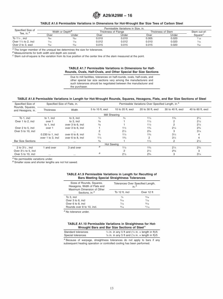
TABLE A1.6 Permissible Variations in Dimensions for Hot-Wrought Bar Size Tees of Carbon Steel
Specified Size ofTee, in.A
Permissible Variations in Size, in.Width or DepthB Thickness of Flange Thickness of Stem Stem out-of-
SquareCOver Under Over Under Over UnderTo 11⁄4 , incl 3⁄64 3⁄64 0.010 0.010 0.005 0.020 1⁄ 32
Over 11⁄4 to 2, incl 1⁄16 1⁄16 0.012 0.012 0.010 0.020 1⁄16
Over 2 to 3, excl 3⁄32 3⁄32 0.015 0.015 0.015 0.020 3⁄32
A The longer member of the unequal tee determines the size for tolerances.B Measurements for both width and depth are overall.C Stem out-of-square is the variation from its true position of the center line of the stem measured at the point.
TABLE A1.7 Permissible Variations in Dimensions for Half-Rounds, Ovals, Half-Ovals, and Other Special Bar Size Sections
Due to mill facilities, tolerances on half-rounds, ovals, half-ovals, andother special bar size sections vary among the manufacturers andsuch tolerances should be negotiated between the manufacturer andthe purchaser.
TABLE A1.8 Permissible Variations in Length for Hot-Wrought Rounds, Squares, Hexagons, Flats, and Bar Size Sections of Steel
Specified Size ofRounds, Squares,and Hexagons, in.
Specified Size of Flats, in. Permissible Variations Over Specified Length, in.A
Thickness Width 5 to 10 ft, excl 10 to 20 ft, excl 20 to 30 ft, excl 30 to 40 ft, excl 40 to 60 ft, excl
Mill ShearingTo 1, incl to 1, incl to 3, incl 1⁄2 3⁄4 11⁄4 13⁄4 21⁄4
Over 1 to 2, incl over 1 to 3, incl 5⁄8 1 11⁄2 2 21⁄2to 1, incl over 3 to 6, incl 5⁄8 1 11⁄2 2 21⁄2
Over 2 to 5, incl over 1 over 3 to 6, incl 1 11⁄2 13⁄4 21⁄4 23⁄4Over 5 to 10, incl ... ... 2 21⁄2 23⁄4 3 31⁄4
0.230 to 1, incl over 6 to 8, incl 3⁄4 11⁄4 13⁄4 31⁄2 4over 1 to 3, incl over 6 to 8, incl 11⁄4 13⁄4 2 31⁄2 4
Bar Size Sections ... ... 5⁄8 1 11⁄2 2 21⁄2Hot Sawing
2 to 31⁄2 , incl 1 and over 3 and over B 11⁄2 13⁄4 21⁄4 23⁄4Over 31⁄2 to 5, incl 2 21⁄4 25⁄8 3Over 5 to 10, incl ... ... B 21⁄2 23⁄4 3 31⁄4
A No permissible variations under.B Smaller sizes and shorter lengths are not hot sawed.
TABLE A1.9 Permissible Variations in Length for Recutting ofBars Meeting Special Straightness Tolerances
Sizes of Rounds, Squares,Hexagons, Width of Flats andMaximum Dimension of Other
Sections, in.A
Tolerances Over Specified Length,in.A
To 12 ft, incl Over 12 ft
To 3, incl 1⁄4 5⁄16
Over 3 to 6, incl 5⁄16 7⁄16
Over 6 to 8, incl 7⁄16 9⁄16
Rounds over 8 to 10, incl. 9⁄16 11⁄16
A No tolerance under.
TABLE A1.10 Permissible Variations in Straightness for Hot-Wrought Bars and Bar Size Sections of SteelA
Standard tolerances 1⁄4 in. in any 5 ft and (1⁄4 in. × length in ft)/5Special tolerances 1⁄8 in. in any 5 ft and (1⁄8 in. × length in ft)/5A Because of warpage, straightness tolerances do not apply to bars if anysubsequent heating operation or controlled cooling has been performed.
A29/A29M − 16
13
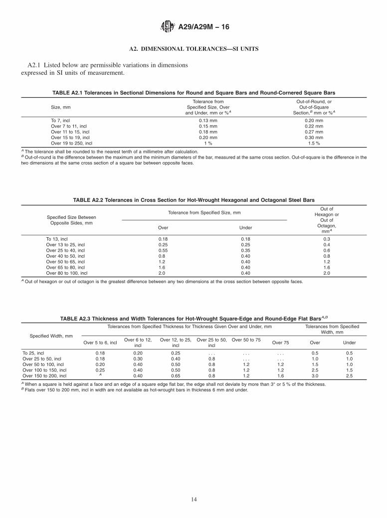
A2. DIMENSIONAL TOLERANCES—SI UNITS
A2.1 Listed below are permissible variations in dimensionsexpressed in SI units of measurement.
TABLE A2.1 Tolerances in Sectional Dimensions for Round and Square Bars and Round-Cornered Square Bars
Size, mmTolerance from
Specified Size, Overand Under, mm or %A
Out-of-Round, orOut-of-Square
Section,B mm or %A
To 7, incl 0.13 mm 0.20 mmOver 7 to 11, incl 0.15 mm 0.22 mmOver 11 to 15, incl 0.18 mm 0.27 mmOver 15 to 19, incl 0.20 mm 0.30 mmOver 19 to 250, incl 1 % 1.5 %
A The tolerance shall be rounded to the nearest tenth of a millimetre after calculation.B Out-of-round is the difference between the maximum and the minimum diameters of the bar, measured at the same cross section. Out-of-square is the difference in thetwo dimensions at the same cross section of a square bar between opposite faces.
TABLE A2.2 Tolerances in Cross Section for Hot-Wrought Hexagonal and Octagonal Steel Bars
Specified Size BetweenOpposite Sides, mm
Tolerance from Specified Size, mmOut of
Hexagon orOut of
Octagon,mmA
Over Under
To 13, incl 0.18 0.18 0.3Over 13 to 25, incl 0.25 0.25 0.4Over 25 to 40, incl 0.55 0.35 0.6Over 40 to 50, incl 0.8 0.40 0.8Over 50 to 65, incl 1.2 0.40 1.2Over 65 to 80, incl 1.6 0.40 1.6Over 80 to 100, incl 2.0 0.40 2.0
A Out of hexagon or out of octagon is the greatest difference between any two dimensions at the cross section between opposite faces.
TABLE A2.3 Thickness and Width Tolerances for Hot-Wrought Square-Edge and Round-Edge Flat BarsA,B
Specified Width, mm
Tolerances from Specified Thickness for Thickness Given Over and Under, mm Tolerances from SpecifiedWidth, mm
Over 5 to 6, inclOver 6 to 12,
inclOver 12, to 25,
inclOver 25 to 50,
inclOver 50 to 75
Over 75 Over Under
To 25, incl 0.18 0.20 0.25 . . . . . . . . . 0.5 0.5Over 25 to 50, incl 0.18 0.30 0.40 0.8 . . . . . . 1.0 1.0Over 50 to 100, incl 0.20 0.40 0.50 0.8 1.2 1.2 1.5 1.0Over 100 to 150, incl 0.25 0.40 0.50 0.8 1.2 1.2 2.5 1.5Over 150 to 200, incl A 0.40 0.65 0.8 1.2 1.6 3.0 2.5
A When a square is held against a face and an edge of a square edge flat bar, the edge shall not deviate by more than 3° or 5 % of the thickness.B Flats over 150 to 200 mm, incl in width are not available as hot-wrought bars in thickness 6 mm and under.
A29/A29M − 16
14
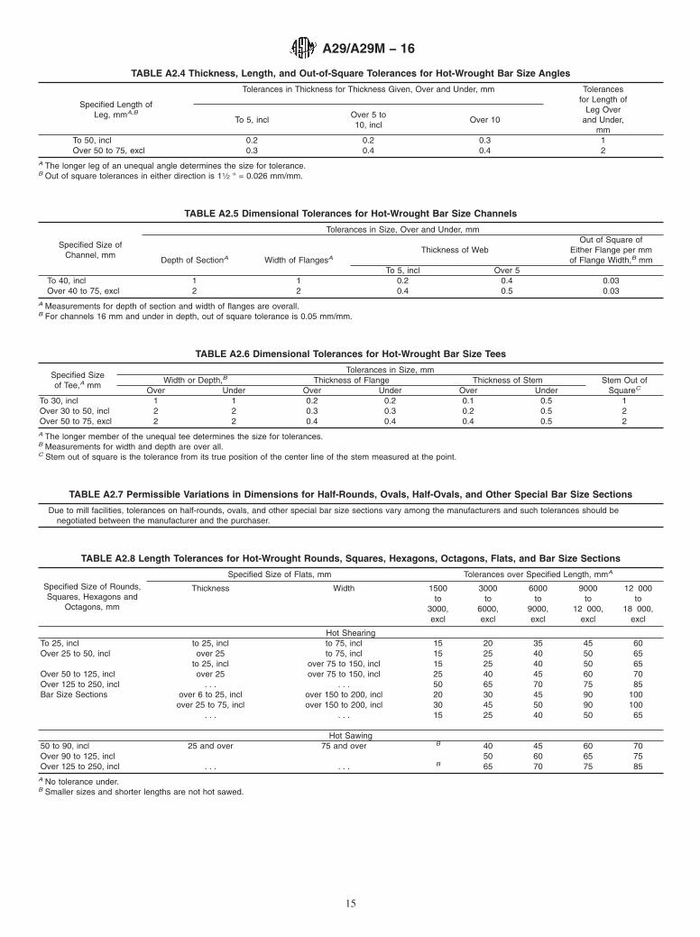
TABLE A2.4 Thickness, Length, and Out-of-Square Tolerances for Hot-Wrought Bar Size Angles
Specified Length ofLeg, mmA,B
Tolerances in Thickness for Thickness Given, Over and Under, mm Tolerancesfor Length of
Leg Overand Under,
mmTo 5, incl
Over 5 to10, incl
Over 10
To 50, incl 0.2 0.2 0.3 1Over 50 to 75, excl 0.3 0.4 0.4 2
A The longer leg of an unequal angle determines the size for tolerance.B Out of square tolerances in either direction is 11⁄2 ° = 0.026 mm/mm.
TABLE A2.5 Dimensional Tolerances for Hot-Wrought Bar Size Channels
Specified Size ofChannel, mm
Tolerances in Size, Over and Under, mm
Depth of SectionA Width of FlangesAThickness of Web
Out of Square ofEither Flange per mmof Flange Width,B mm
To 5, incl Over 5To 40, incl 1 1 0.2 0.4 0.03Over 40 to 75, excl 2 2 0.4 0.5 0.03
A Measurements for depth of section and width of flanges are overall.B For channels 16 mm and under in depth, out of square tolerance is 0.05 mm/mm.
TABLE A2.6 Dimensional Tolerances for Hot-Wrought Bar Size Tees
Specified Sizeof Tee,A mm
Tolerances in Size, mmWidth or Depth,B Thickness of Flange Thickness of Stem Stem Out of
SquareCOver Under Over Under Over UnderTo 30, incl 1 1 0.2 0.2 0.1 0.5 1Over 30 to 50, incl 2 2 0.3 0.3 0.2 0.5 2Over 50 to 75, excl 2 2 0.4 0.4 0.4 0.5 2A The longer member of the unequal tee determines the size for tolerances.B Measurements for width and depth are over all.C Stem out of square is the tolerance from its true position of the center line of the stem measured at the point.
TABLE A2.7 Permissible Variations in Dimensions for Half-Rounds, Ovals, Half-Ovals, and Other Special Bar Size Sections
Due to mill facilities, tolerances on half-rounds, ovals, and other special bar size sections vary among the manufacturers and such tolerances should benegotiated between the manufacturer and the purchaser.
TABLE A2.8 Length Tolerances for Hot-Wrought Rounds, Squares, Hexagons, Octagons, Flats, and Bar Size Sections
Specified Size of Rounds,Squares, Hexagons and
Octagons, mm
Specified Size of Flats, mm Tolerances over Specified Length, mmA
Thickness Width 1500 3000 6000 9000 12 000to to to to to
3000, 6000, 9000, 12 000, 18 000,excl excl excl excl excl
Hot ShearingTo 25, incl to 25, incl to 75, incl 15 20 35 45 60Over 25 to 50, incl over 25 to 75, incl 15 25 40 50 65
to 25, incl over 75 to 150, incl 15 25 40 50 65Over 50 to 125, incl over 25 over 75 to 150, incl 25 40 45 60 70Over 125 to 250, incl . . . . . . 50 65 70 75 85Bar Size Sections over 6 to 25, incl over 150 to 200, incl 20 30 45 90 100
over 25 to 75, incl over 150 to 200, incl 30 45 50 90 100. . . . . . 15 25 40 50 65
Hot Sawing50 to 90, incl 25 and over 75 and over B 40 45 60 70Over 90 to 125, incl 50 60 65 75Over 125 to 250, incl . . . . . . B 65 70 75 85
A No tolerance under.B Smaller sizes and shorter lengths are not hot sawed.
A29/A29M − 16
15
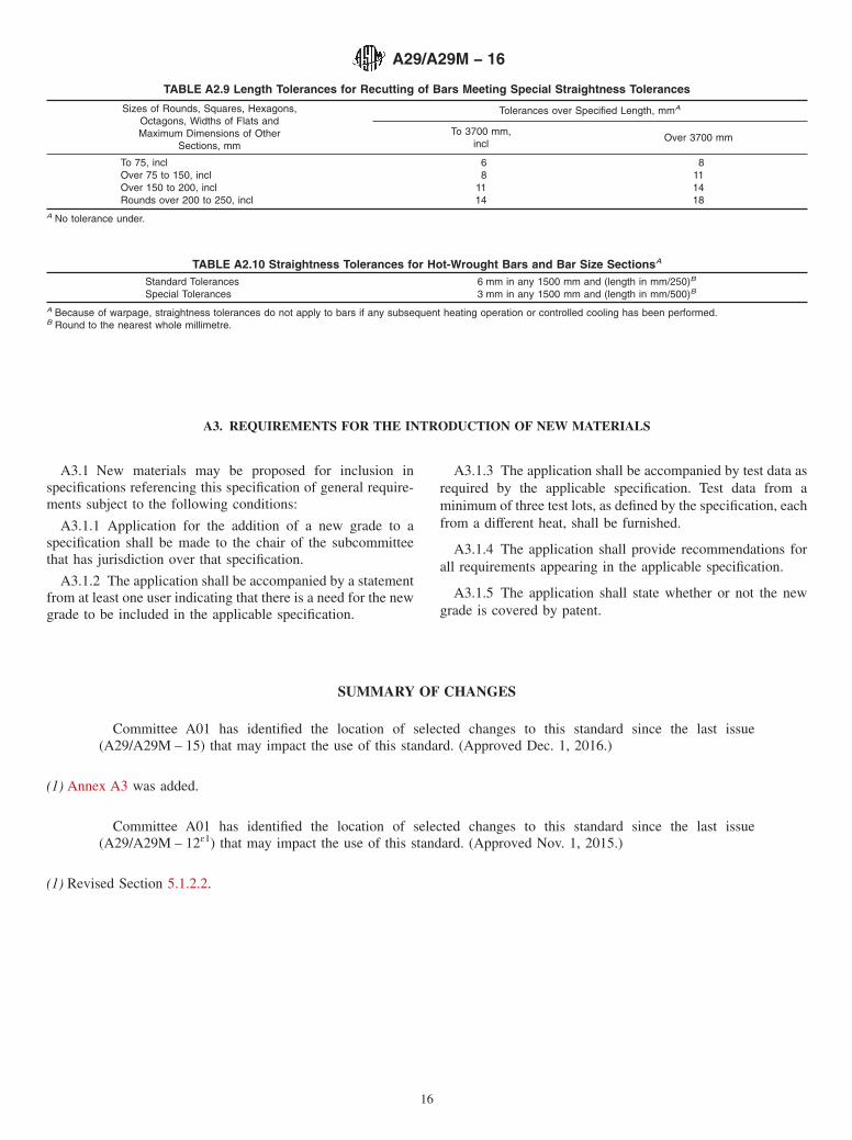
A3. REQUIREMENTS FOR THE INTRODUCTION OF NEW MATERIALS
A3.1 New materials may be proposed for inclusion inspecifications referencing this specification of general require-ments subject to the following conditions:
A3.1.1 Application for the addition of a new grade to aspecification shall be made to the chair of the subcommitteethat has jurisdiction over that specification.
A3.1.2 The application shall be accompanied by a statementfrom at least one user indicating that there is a need for the newgrade to be included in the applicable specification.
A3.1.3 The application shall be accompanied by test data asrequired by the applicable specification. Test data from aminimum of three test lots, as defined by the specification, eachfrom a different heat, shall be furnished.
A3.1.4 The application shall provide recommendations forall requirements appearing in the applicable specification.
A3.1.5 The application shall state whether or not the newgrade is covered by patent.
SUMMARY OF CHANGES
Committee A01 has identified the location of selected changes to this standard since the last issue(A29/A29M – 15) that may impact the use of this standard. (Approved Dec. 1, 2016.)
(1) Annex A3 was added.
Committee A01 has identified the location of selected changes to this standard since the last issue(A29/A29M – 12ɛ1) that may impact the use of this standard. (Approved Nov. 1, 2015.)
(1) Revised Section 5.1.2.2.
TABLE A2.9 Length Tolerances for Recutting of Bars Meeting Special Straightness Tolerances
Sizes of Rounds, Squares, Hexagons,Octagons, Widths of Flats andMaximum Dimensions of Other
Sections, mm
Tolerances over Specified Length, mmA
To 3700 mm,incl
Over 3700 mm
To 75, incl 6 8Over 75 to 150, incl 8 11Over 150 to 200, incl 11 14Rounds over 200 to 250, incl 14 18
A No tolerance under.
TABLE A2.10 Straightness Tolerances for Hot-Wrought Bars and Bar Size SectionsA
Standard Tolerances 6 mm in any 1500 mm and (length in mm/250)B
Special Tolerances 3 mm in any 1500 mm and (length in mm/500)B
A Because of warpage, straightness tolerances do not apply to bars if any subsequent heating operation or controlled cooling has been performed.B Round to the nearest whole millimetre.
A29/A29M − 16
16
ASTM International takes no position respecting the validity of any patent rights asserted in connection with any item mentionedin this standard. Users of this standard are expressly advised that determination of the validity of any such patent rights, and the riskof infringement of such rights, are entirely their own responsibility.
This standard is subject to revision at any time by the responsible technical committee and must be reviewed every five years andif not revised, either reapproved or withdrawn. Your comments are invited either for revision of this standard or for additional standardsand should be addressed to ASTM International Headquarters. Your comments will receive careful consideration at a meeting of theresponsible technical committee, which you may attend. If you feel that your comments have not received a fair hearing you shouldmake your views known to the ASTM Committee on Standards, at the address shown below.
This standard is copyrighted by ASTM International, 100 Barr Harbor Drive, PO Box C700, West Conshohocken, PA 19428-2959,United States. Individual reprints (single or multiple copies) of this standard may be obtained by contacting ASTM at the aboveaddress or at 610-832-9585 (phone), 610-832-9555 (fax), or [email protected] (e-mail); or through the ASTM website(www.astm.org). Permission rights to photocopy the standard may also be secured from the Copyright Clearance Center, 222Rosewood Drive, Danvers, MA 01923, Tel: (978) 646-2600; http://www.copyright.com/
A29/A29M − 16
17