din/iso 6431 - elhinel srl = 32 ÷ 125 din/iso 6431 magnetic modifications m= standard, magnetic...
TRANSCRIPT
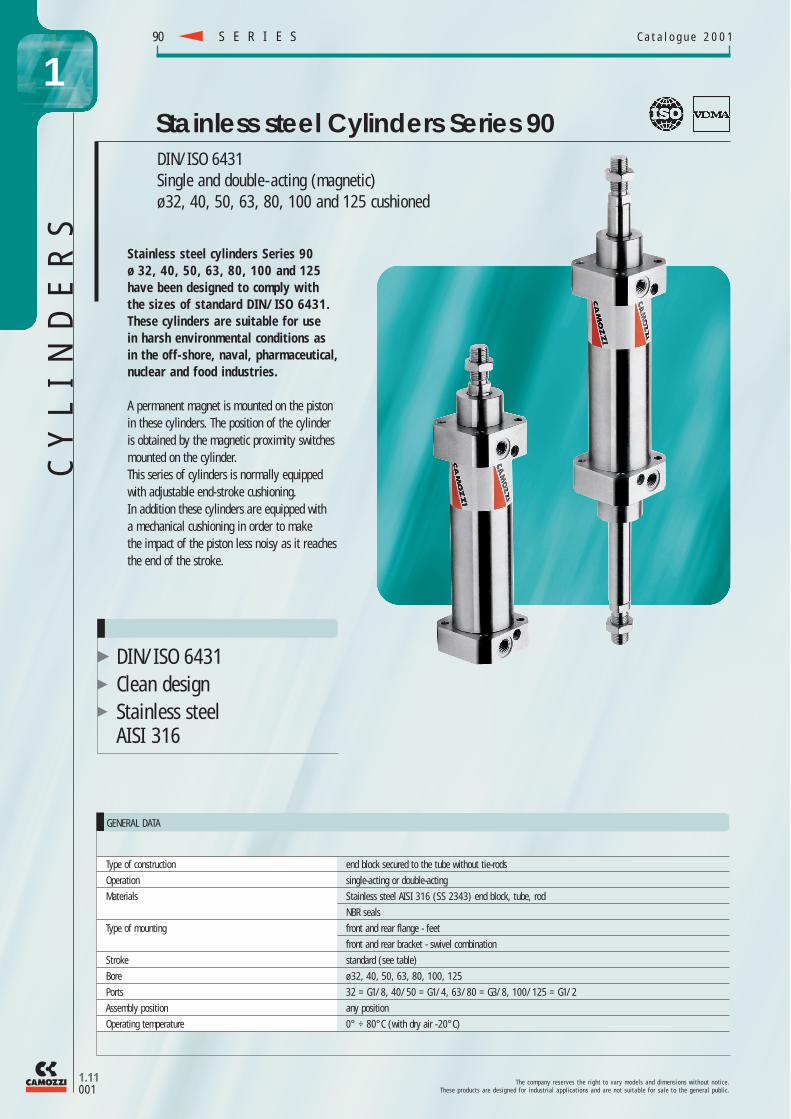
DIN/ISO 6431Single and double-acting (magnetic)ø 32, 40, 50, 63, 80, 100 and 125 cushioned
Stainless steel Cylinders Series 90
T h e c o m p a n y r e s e r v e s t h e r i g h t t o v a r y m o d e l s a n d d i m e n s i o n s w i t h o u t n o t i c e .T h e s e p r o d u c t s a r e d e s i g n e d f o r i n d u s t r i a l a p p l i c a t i o n s a n d a r e n o t s u i t a b l e f o r s a l e t o t h e g e n e r a l p u b l i c .
S E R I E S90 C a t a l o g u e 2 0 0 1
1.11001
1
Type of construction end block secured to the tube without tie-rods
Operation single-acting or double-acting
Materials Stainless steel AISI 316 (SS 2343) end block, tube, rod
NBR seals
Type of mounting front and rear flange - feet
front and rear bracket - swivel combination
Stroke standard (see table)
Bore ø 32, 40, 50, 63, 80, 100, 125
Ports 32 = G1/8, 40/50 = G1/4, 63/80 = G3/8, 100/125 = G1/2
Assembly position any position
Operating temperature 0° ÷ 80°C (with dry air - 20°C)
GENERAL DATA
CY
LI
ND
ER
S
Stainless steel cylinders Series 90ø 32, 40, 50, 63, 80, 100 and 125have been designed to comply withthe sizes of standard DIN/ISO 6431.These cylinders are suitable for usein harsh environmental conditions asin the off-shore, naval, pharmaceutical,nuclear and food industries.
A permanent magnet is mounted on the pistonin these cylinders. The position of the cylinderis obtained by the magnetic proximity switchesmounted on the cylinder. This series of cylinders is normally equippedwith adjustable end-stroke cushioning.In addition these cylinders are equipped witha mechanical cushioning in order to makethe impact of the piston less noisy as it reachesthe end of the stroke.
DIN/ISO 6431Clean designStainless steelAISI 316
CY
LI
ND
ER
S
T h e c o m p a n y r e s e r v e s t h e r i g h t t o v a r y m o d e l s a n d d i m e n s i o n s w i t h o u t n o t i c e .T h e s e p r o d u c t s a r e d e s i g n e d f o r i n d u s t r i a l a p p l i c a t i o n s a n d a r e n o t s u i t a b l e f o r s a l e t o t h e g e n e r a l p u b l i c .
S E R I E SC a t a l o g u e 2 0 0 1
190
1.11002
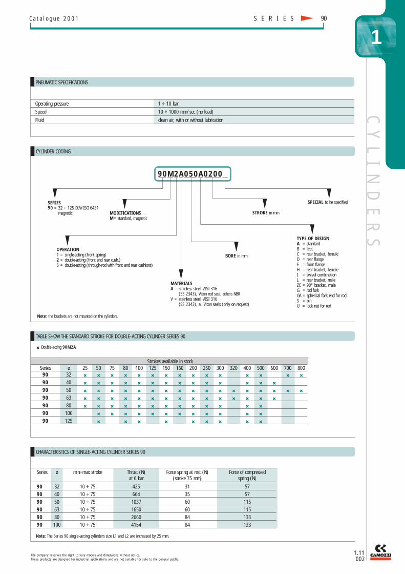
CYLINDER CODING
Note: the brackets are not mounted on the cylinders.
Operating pressure 1 ÷ 10 bar
Speed 10 ÷ 1000 mm/sec (no load)
Fluid clean air, with or without lubrication
PNEUMATIC SPECIFICATIONS
SERIES90 = 32 ÷ 125 DIN/ISO 6431
magnetic MODIFICATIONSM = standard, magnetic
OPERATION1 = single-acting (front spring)2 = double-acting (front and rear cush.) 6 = double-acting (through - rod with front and rear cushions)
MATERIALSA = stainless steel AISI 316
(SS 2343), Viton rod seal, others NBRV = stainless steel AISI 316
(SS 2343), all Viton seals (only on request)
BORE in mm
TYPE OF DESIGNA = standardB = feetC = rear bracket, femaleD = rear flangeE = front flangeH = rear bracket, femaleI = swivel combinationL = rear bracket, maleZC = 90° bracket, maleG = rod forkGA = spherical fork end for rodS = pinU = lock nut for rod
STROKE in mm
SPECIAL to be specified
Strokes available in stockSeries ø 25 50 75 80 100 125 150 160 200 250 300 320 400 500 600 700 80090 32 ✖ ✖ ✖ ✖ ✖ ✖ ✖ ✖ ✖ ✖ ✖ ✖ ✖ ✖ ✖
90 40 ✖ ✖ ✖ ✖ ✖ ✖ ✖ ✖ ✖ ✖ ✖ ✖ ✖ ✖
90 50 ✖ ✖ ✖ ✖ ✖ ✖ ✖ ✖ ✖ ✖ ✖ ✖ ✖ ✖ ✖ ✖ ✖
90 63 ✖ ✖ ✖ ✖ ✖ ✖ ✖ ✖ ✖ ✖ ✖ ✖ ✖ ✖ ✖
90 80 ✖ ✖ ✖ ✖ ✖ ✖ ✖ ✖ ✖ ✖ ✖ ✖ ✖
90 100 ✖ ✖ ✖ ✖ ✖ ✖ ✖ ✖ ✖ ✖ ✖ ✖
90 125 ✖ ✖ ✖ ✖ ✖ ✖ ✖ ✖ ✖
TABLE SHOW THE STANDARD STROKE FOR DOUBLE-ACTING CYLINDER SERIES 90
CHARACTERISTICS OF SINGLE-ACTING CYLINDER SERIES 90
Series ø min÷max stroke Thrust (N) Force spring at rest (N) Force of compressedat 6 bar (stroke 75 mm) spring (N)
90 32 10 ÷ 75 425 31 5790 40 10 ÷ 75 664 35 5790 50 10 ÷ 75 1037 60 11590 63 10 ÷ 75 1650 60 11590 80 10 ÷ 75 2660 84 13390 100 10 ÷ 75 4154 84 133
Note: The Series 90 single-acting cylinders size L1 and L2 are increased by 25 mm.
✖ Double -acting 90M2A
90M2A050A0200
CY
LI
ND
ER
S
T h e c o m p a n y r e s e r v e s t h e r i g h t t o v a r y m o d e l s a n d d i m e n s i o n s w i t h o u t n o t i c e .T h e s e p r o d u c t s a r e d e s i g n e d f o r i n d u s t r i a l a p p l i c a t i o n s a n d a r e n o t s u i t a b l e f o r s a l e t o t h e g e n e r a l p u b l i c .
S E R I E S90 C a t a l o g u e 2 0 0 1
1.11003
1
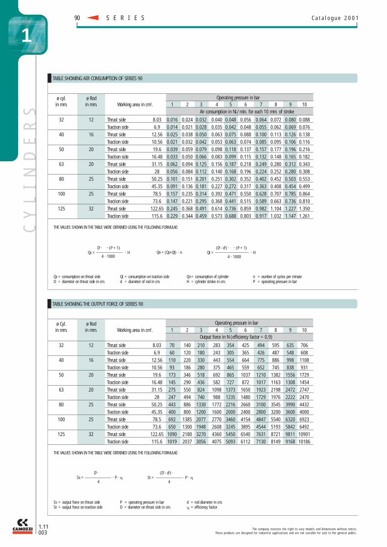
TABLE SHOWING AIR CONSUMPTION OF SERIES 90
ø cyl. ø Rod Operating pressure in barin mm. in mm. Working area in cm2. 1 2 3 4 5 6 7 8 9 10
Air consumption in NL/min. for each 10 mm. of stroke
32 12 Thrust side 8.03 0.016 0.024 0.032 0.040 0.048 0.056 0.064 0.072 0.080 0.088Traction side 6.9 0.014 0.021 0.028 0.035 0.042 0.048 0.055 0.062 0.069 0.076
40 16 Thrust side 12.56 0.025 0.038 0.050 0.063 0.075 0.088 0.100 0.113 0.126 0.138Traction side 10.56 0.021 0.032 0.042 0.053 0.063 0.074 0.085 0.095 0.106 0.116
50 20 Thrust side 19.6 0.039 0.059 0.079 0.098 0.118 0.137 0.157 0.177 0.196 0.216Traction side 16.48 0.033 0.050 0.066 0.083 0.099 0.115 0.132 0.148 0.165 0.182
63 20 Thrust side 31.15 0.062 0.094 0.125 0.156 0.187 0.218 0.249 0.280 0.312 0.343Traction side 28 0.056 0.084 0.112 0.140 0.168 0.196 0.224 0.252 0.280 0.308
80 25 Thrust side 50.25 0.101 0.151 0.201 0.251 0.302 0.352 0.402 0.452 0.503 0.553Traction side 45.35 0.091 0.136 0.181 0.227 0.272 0.317 0.363 0.408 0.454 0.499
100 25 Thrust side 78.5 0.157 0.235 0.314 0.392 0.471 0.550 0.628 0.707 0.785 0.864Traction side 73.6 0.147 0.221 0.295 0.368 0.441 0.515 0.589 0.663 0.736 0.810
125 32 Thrust side 122.65 0.245 0.368 0.491 0.614 0.736 0.859 0.982 1.104 1.227 1.350Traction side 115.6 0.229 0.344 0.459 0.573 0.688 0.803 0.917 1.032 1.147 1.261
TABLE SHOWING THE OUTPUT FORCE OF SERIES 90
ø Cyl. ø Rod Operating pressure in barin mm. in mm. Working area in cm2. 1 2 3 4 5 6 7 8 9 10
Output force in N (efficiency factor = 0,9)
32 12 Thrust side 8.03 70 140 210 283 354 425 494 595 635 706Traction side 6.9 60 120 180 243 305 365 426 487 548 608
40 16 Thrust side 12.56 110 220 330 443 554 664 775 886 998 1108Traction side 10.56 93 186 280 375 465 559 652 745 838 931
50 20 Thrust side 19.6 173 346 518 692 865 1037 1210 1382 1556 1729Traction side 16.48 145 290 436 582 727 872 1017 1163 1308 1454
63 20 Thrust side 31.15 275 550 824 1098 1373 1650 1923 2198 2472 2747Traction side 28 247 494 740 988 1235 1480 1729 1976 2222 2470
80 25 Thrust side 50.25 443 886 1330 1772 2216 2660 3100 3545 3990 4432Traction side 45.35 400 800 1200 1600 2000 2400 2800 3200 3600 4000
100 25 Thrust side 78.5 692 1385 2077 2770 3460 4154 4847 5540 6320 6923Traction side 73.6 650 1300 1948 2608 3245 3895 4544 5193 5842 6492
125 32 Thrust side 122.65 1090 2180 3270 4360 5450 6540 7631 8721 9811 10901Traction side 115.6 1019 2037 3056 4075 5093 6112 7130 8149 9168 10186
THE VALUES SHOWN IN THE TABLE WERE OBTAINED USING THE FOLLOWING FORMULAE:
D2 . . (P + 1)Qs = . H
4 . 1000
(D2 - d2) . . (P + 1)Qt = . H
4 . 1000Qn = (Qs+Qt) · n
Qs = consumption on thrust sideD = diameter on thrust side in cm.
Qt = consumption on traction sided = diameter of rod in cm.
Qn = consumption of cylinderH = cylinder stroke in cm.
n = number of cycles per minuteP = operating pressure in bar
THE VALUES SHOWN IN THE TABLE WERE OBTAINED USING THE FOLLOWING FORMULAE:
Ss = output force on thrust sideSt = output force on traction side
P = operating pressure in barD = diameter on thrust side in cm.
d = rod diameter in cm.η = efficiency factor
D2 .Ss = . P . η
4
(D2 - d2) .St = . P . η
4

DIMENSIONS
Series ø cyl. A AM B E F I KK L2 P SW1 TG WH90 32 12 22 30 45 16 G1/8 M10x1,25 120 M6 10 32,5 2690 40 16 24 35 55 20 G1/4 M12x1,25 135 M6 13 38 3090 50 20 32 40 65 25 G1/4 M16x1,5 143 M8 17 46,5 3790 63 20 32 45 75 25 G3/8 M16x1,5 158 M8 17 56,5 3790 80 25 40 45 95 33 G3/8 M20x1,5 174 M10 22 72 4690 100 25 40 55 115 37 G1/2 M20x1,5 189 M10 22 89 5190 125 32 54 60 140 45 G1/2 M27x2 225 M12 27 110 65
DIMENSIONS
Series ø cyl. A AM B E F I KK L1 P SW1 TG WH90 32 12 22 30 45 16 G1/8 M10x1,25 94 M6 10 32,5 2690 40 16 24 35 55 20 G1/4 M12x1,25 105 M6 13 38 3090 50 20 32 40 65 25 G1/4 M16x1,5 106 M8 17 46,5 3790 63 20 32 45 75 25 G3/8 M16x1,5 121 M8 17 56,5 3790 80 25 40 45 95 33 G3/8 M20x1,5 128 M10 22 72 4690 100 25 40 55 115 37 G1/2 M20x1,5 138 M10 22 89 5190 125 32 54 60 140 45 G1/2 M27x2 160 M12 27 110 65
CY
LI
ND
ER
S
T h e c o m p a n y r e s e r v e s t h e r i g h t t o v a r y m o d e l s a n d d i m e n s i o n s w i t h o u t n o t i c e .T h e s e p r o d u c t s a r e d e s i g n e d f o r i n d u s t r i a l a p p l i c a t i o n s a n d a r e n o t s u i t a b l e f o r s a l e t o t h e g e n e r a l p u b l i c .
1.11004
S E R I E S 90C a t a l o g u e 2 0 0 1
1
Cylinders Series 90
Cylinders Series 90
Through rod.
(+ add the stroke)
(+ add the stroke)
CY
LI
ND
ER
S
T h e c o m p a n y r e s e r v e s t h e r i g h t t o v a r y m o d e l s a n d d i m e n s i o n s w i t h o u t n o t i c e .T h e s e p r o d u c t s a r e d e s i g n e d f o r i n d u s t r i a l a p p l i c a t i o n s a n d a r e n o t s u i t a b l e f o r s a l e t o t h e g e n e r a l p u b l i c .
C a t a l o g u e 2 0 0 1
1.11005
1
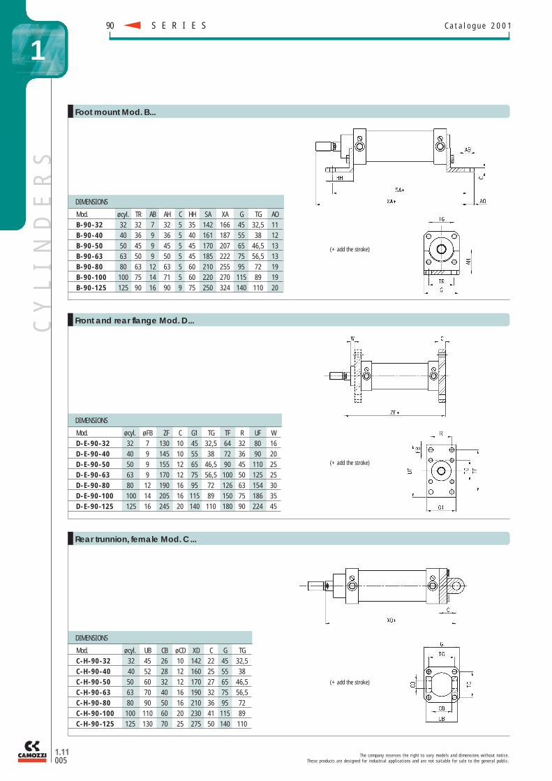
DIMENSIONS
Mod. ø cyl. TR AB AH C HH SA XA G TG AOB-90-32 32 32 7 32 5 35 142 166 45 32,5 11B-90-40 40 36 9 36 5 40 161 187 55 38 12B-90-50 50 45 9 45 5 45 170 207 65 46,5 13B-90-63 63 50 9 50 5 45 185 222 75 56,5 13B-90-80 80 63 12 63 5 60 210 255 95 72 19B-90-100 100 75 14 71 5 60 220 270 115 89 19B-90-125 125 90 16 90 9 75 250 324 140 110 20
Foot mount Mod. B...
(+ add the stroke)
(+ add the stroke)
(+ add the stroke)
DIMENSIONS
Mod. ø cyl. UB CB ø CD XD C G TGC-H-90-32 32 45 26 10 142 22 45 32,5C-H-90-40 40 52 28 12 160 25 55 38C-H-90-50 50 60 32 12 170 27 65 46,5C-H-90-63 63 70 40 16 190 32 75 56,5C-H-90-80 80 90 50 16 210 36 95 72C-H-90-100 100 110 60 20 230 41 115 89C-H-90-125 125 130 70 25 275 50 140 110
DIMENSIONS
Mod. ø cyl. ø FB ZF C G1 TG TF R UF WD-E-90-32 32 7 130 10 45 32,5 64 32 80 16D-E-90-40 40 9 145 10 55 38 72 36 90 20D-E-90-50 50 9 155 12 65 46,5 90 45 110 25D-E-90-63 63 9 170 12 75 56,5 100 50 125 25D-E-90-80 80 12 190 16 95 72 126 63 154 30D-E-90-100 100 14 205 16 115 89 150 75 186 35D-E-90-125 125 16 245 20 140 110 180 90 224 45
Front and rear flange Mod. D...
Rear trunnion, female Mod. C...
S E R I E S90
DIMENSIONS
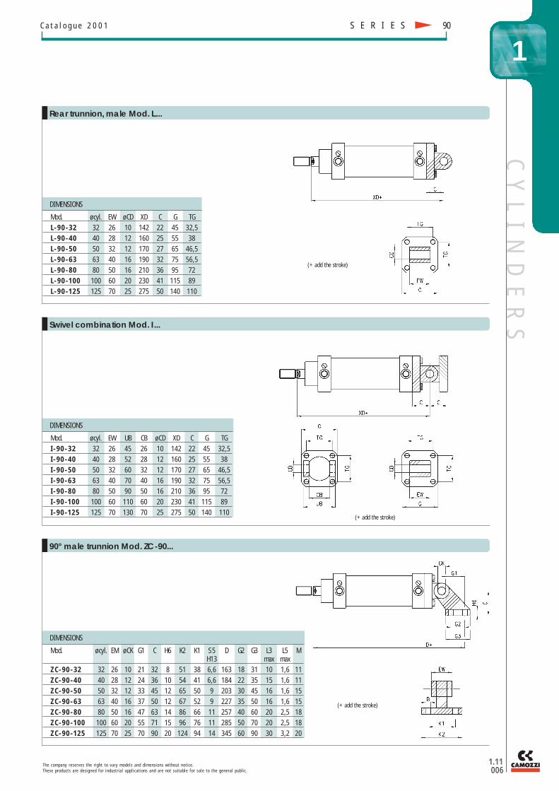
Mod. ø cyl. EM ø CK G1 C H6 K2 K1 S 5 D G2 G3 L3 L5 MH13 max max
ZC-90-32 32 26 10 21 32 8 51 38 6,6 163 18 31 10 1,6 11ZC-90-40 40 28 12 24 36 10 54 41 6,6 184 22 35 15 1,6 11ZC-90-50 50 32 12 33 45 12 65 50 9 203 30 45 16 1,6 15ZC-90-63 63 40 16 37 50 12 67 52 9 227 35 50 16 1,6 15ZC-90-80 80 50 16 47 63 14 86 66 11 257 40 60 20 2,5 18ZC-90-100 100 60 20 55 71 15 96 76 11 285 50 70 20 2,5 18ZC-90-125 125 70 25 70 90 20 124 94 14 345 60 90 30 3,2 20
DIMENSIONS
Mod. ø cyl. EW UB CB ø CD XD C G TGI -90-32 32 26 45 26 10 142 22 45 32,5I -90-40 40 28 52 28 12 160 25 55 38I -90-50 50 32 60 32 12 170 27 65 46,5I -90-63 63 40 70 40 16 190 32 75 56,5I -90-80 80 50 90 50 16 210 36 95 72I -90-100 100 60 110 60 20 230 41 115 89I -90-125 125 70 130 70 25 275 50 140 110
CY
LI
ND
ER
S
T h e c o m p a n y r e s e r v e s t h e r i g h t t o v a r y m o d e l s a n d d i m e n s i o n s w i t h o u t n o t i c e .T h e s e p r o d u c t s a r e d e s i g n e d f o r i n d u s t r i a l a p p l i c a t i o n s a n d a r e n o t s u i t a b l e f o r s a l e t o t h e g e n e r a l p u b l i c .
1.11006
C a t a l o g u e 2 0 0 1
1
DIMENSIONS
Mod. ø cyl. EW ø CD XD C G TGL-90-32 32 26 10 142 22 45 32,5L-90-40 40 28 12 160 25 55 38L-90-50 50 32 12 170 27 65 46,5L-90-63 63 40 16 190 32 75 56,5L-90-80 80 50 16 210 36 95 72L-90-100 100 60 20 230 41 115 89L-90-125 125 70 25 275 50 140 110
Rear trunnion, male Mod. L...
(+ add the stroke)
(+ add the stroke)
(+ add the stroke)
Swivel combination Mod. I...
90° male trunnion Mod. ZC-90...
S E R I E S 90
DIMENSIONS
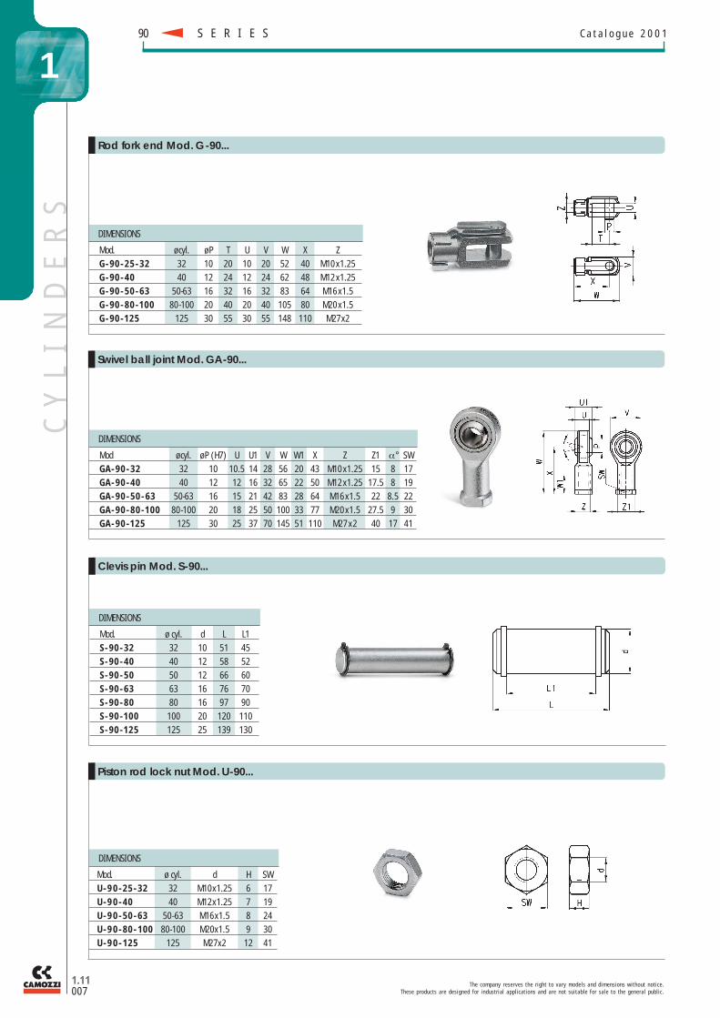
Mod. ø cyl. d H SWU-90-25-32 32 M10x1.25 6 17U-90-40 40 M12x1.25 7 19U-90-50-63 50-63 M16x1.5 8 24U-90-80-100 80-100 M20x1.5 9 30U-90-125 125 M27x2 12 41
DIMENSIONS
Mod. ø cyl. d L L1S-90-32 32 10 51 45S-90-40 40 12 58 52S-90-50 50 12 66 60S-90-63 63 16 76 70S-90-80 80 16 97 90S-90-100 100 20 120 110S-90-125 125 25 139 130
DIMENSIONS
Mod ø cyl. ø P (H7) U U1 V W W1 X Z Z1 α° SWGA-90-32 32 10 10.5 14 28 56 20 43 M10 x1.25 15 8 17GA-90-40 40 12 12 16 32 65 22 50 M12 x1.25 17.5 8 19GA-90-50-63 50-63 16 15 21 42 83 28 64 M16 x1.5 22 8.5 22GA-90-80-100 80-100 20 18 25 50 100 33 77 M20 x1.5 27.5 9 30GA-90-125 125 30 25 37 70 145 51 110 M27 x 2 40 17 41
DIMENSIONS
Mod. ø cyl. ø P T U V W X ZG-90-25-32 32 10 20 10 20 52 40 M10 x1.25G-90-40 40 12 24 12 24 62 48 M12 x1.25G-90-50-63 50-63 16 32 16 32 83 64 M16 x1.5G-90-80-100 80-100 20 40 20 40 105 80 M20 x1.5G-90-125 125 30 55 30 55 148 110 M27x2
CY
LI
ND
ER
S
T h e c o m p a n y r e s e r v e s t h e r i g h t t o v a r y m o d e l s a n d d i m e n s i o n s w i t h o u t n o t i c e .T h e s e p r o d u c t s a r e d e s i g n e d f o r i n d u s t r i a l a p p l i c a t i o n s a n d a r e n o t s u i t a b l e f o r s a l e t o t h e g e n e r a l p u b l i c .
S E R I E S90 C a t a l o g u e 2 0 0 1
1.11007
1
Rod fork end Mod. G-90...
Swivel ball joint Mod. GA-90...
Piston rod lock nut Mod. U-90...
Clevis pin Mod. S-90...