dip - c&k components · dip product selection guide dip h h–2 dimensions are shown:inch (mm)...
TRANSCRIPT


DIPProduct Selection Guide
DIP
H
H–2
Dimensions are shown: Inch (mm) Specifications and dimensions subject to change
www.ckswitches.com
Series BPA TDD SPA RTE CD CRD
Switch TypeSide actuated Jumper Switch
Single In-line Package
Rotary & Coded8 mm Coded
Rotary10 mm Coded
Rotary
No. of Positions 1-12(except 11)
12-10
(even only)1, 10, 16 1, 10, 16 10, 16
Contact Style SPST SPDT SPST Coded Coded Coded
Profile off PCB
.287 (7.3) Thru-hole
.277 (7,04) SMT.090 (2,3)
.244 (6,2) Vertical .169 (4,3) Rt.
Angle
.167 (4,25) Thru-hole
.335 (8,5) Rt. angle
.168 (4,27) Thru-hole
.340 (8,6) Rt. angle
.272 (6,9) Vertical .414 (10.5) Rt. angle
Process Sealed Washable (tape not required)
Washable with tape seal
Washable (tape not required)
NAWashable (tape
not required)Washable (tape
not required)
Extended Actuator • • • •
Flush Actuator • • • • •
Thru-hole • • • • •
Vertical • • • • •
Right Angle • • • • •
Surface Mount • • • • • •
Tape & Reel (SMT only) • • • • • •
Maximum Current 100mA 100mA 10mA 100mA 0.4VA 0.4VA
Retention Feature • • • C option
Page No. H–24 H–27 H–29 H–31 H–37 H–41
DIP
Series TDP TDA SDA SDB SD BD BDB
Switch Type Half-pitch .050” Side actuated
Half-pitch .050”
Low Profile Low Profile Low Profile Standard Profile Standard Profile
No. of Positions 2-10 (even only)
1 & 2-10 (even only)
1-12(except 11)
1-12(except 11)
2-12(except 11)
1-12(except 11)
2-12(except 11)
Contact Style SPST SPST SPST SPST SPST SPST SPST
Profile off PCB .173 (4,4) .087 (2,2)
.189 (4,80) Thru-hole
.177 (4,5) SMT
.189 (4,80) Thru-hole
.177 (4,5) SMT
.168 (4,27) Thru-hole
.160 (4,06) SMT
.297 (7,55) Vertical .380 (9,65) Rt.
AngleSee Datasheet
Process Sealed Washable with tape seal
Washable with tape seal
Washable (tape not required)
Washable (tape not required)
Washable with tape seal
Washable (tape not required)
Washable (tape not required)
Extended Actuator • • • • • •
Flush Actuator • • • • •
Thru-hole • • • • •
Vertical • • • • • •
Right Angle • •
Surface Mount • • • • •
Tape & Reel (SMT only) • • • • •
Maximum Current 100mA 100mA 100mA 100mA 100mA 100mA 100mA
Page No. H–3 H–6 H–9 H–13 H–17 H–20 H–22

DIP
H
H–3
Dimensions are shown: Inch (mm) Specifications and dimensions subject to change
www.ckswitches.com
TDP SeriesUltra-miniature Surface Mount
Half-pitch Side-Actuated DIP Switches
SpecificationsSWITCH FUNCTION: SPST — 2, 4, 6, 8, 10 positions.
CONTACT RATING:
24 V DC, 25 mA (switching).
50 V DC, 100 mA (steady state).
MECHANICAL AND ELECTRICAL LIFE: 1,000 cycles.
CONTACT RESISTANCE: 100 mΩ max.
INSULATION RESISTANCE: 100 MΩ @ 100 V DC min.
DIELECTRIC STRENGTH: 300 V AC min.
STORAGE TEMPERATURE: –40°C to 85°C.
OPERATING TEMPERATURE: –40°C to 85°C.
OPERATING FORCE: 4,9N max.
SOLDERABILITY: Per MIL-STD-202F method 208D, or
EIA RS-186E method 9 (1 hour steam aging).
PACKAGING: Switches supplied in rigid dispensing tubes in full tube quantities only, this may affect order quantity. Tape and reel packaging also available.
Features/Benefits• World’s first ultra-miniature SMT half-pitch
side-actuated DIP• Side actuation allows visual indication of
on/off position in horizontal applications• Process sealed for surface mount soldering
and washable processing• RoHS compliant• Lead free
Typical Applications• Hand-held electronic devices• Portable computer and
electronic devices• Instrumentation and controls
MaterialsCASE & COVER: glass filled PPS (UL94V-0).
ACTUATOR: PA6T (UL94V-0).
CONTACTS: Copper alloy with gold plate over nickel plate.
TERMINALS: Copper alloy, with gold over nickel plate.
All terminals are insert molded.
TAPE SEAL: Polyimide.
Note: Specifications and materials listed above are for switches with standard options.
For information on specific and custom switches, consult Customer Service Center.
DesignationTDP
Numberof Positions0204060810
ActuatorH0 Flush ActuatorH1 Extended Actuator
TerminationsS Gull wing
Contact MaterialB Gold
Tape Seal(None) with tapeD No tape
Terminal Seal1 Terminals are sealed
Packaging(None) TubesR Tape and Reel
T D P BS 1
Note: Tape seal is not available with H1 Extended Actuators.
How To OrderThe Build-A Switch concept allows you to mix and match options to create the switch you need. Below is a complete listing of options shown in catalog. To order, simply select desired option from each category and place in the appropriate box.
All switches supplied in “OFF” position.

DIP
H
H–4
Dimensions are shown: Inch (mm) Specifications and dimensions subject to change
www.ckswitches.com
Flush Actuator-No Top Tape, Surface Mount Terminals
NO. DIM DIM QUANTITYPART NUMBER POS. ‘A’ “B” PER TUBE
TDP02H0SBD1 2 0.144 (3,67) 0.050 (1,27) 125
TDP04H0SBD1 4 0.244 (6,21) 0.150 (3,81) 70
TDP06H0SBD1 6 0.344 (8,74) 0.250 (6,35) 50
TDP08H0SBD1 8 0.444 (11,29) 0.350 (8,89) 40
TDP10H0SBD1 10 0.544 (13,82) 0.450 (11,43) 30
Schematic
SPST
TDP SeriesUltra-miniature Surface Mount Half-pitch Side-Actuated DIP Switches
0.022(0,57)
0.042(1,06)
0.320(8,12)
0.006(0,15)
0.228(5,8)
100
0.236(6,0)
0.030(0,76)
0.050(1,27)
0.300(7,62)
0.250(6,35) 0.350
(8,89)
DIM 'B'
0.161(4,1)
0.023(0,6)
0.012/0.004(0,3/0,1)
ON 1 2 3 4 5 6 7 8
CHAMFER
0.047(1,2)
0.050 TYP.(1,27)
DIM 'A'
0.018(0,45)
DATE CODE
2X 0.039 (1,0)
TDP085A
C&K
1 2 3 4 5 6 7 8
CHAMFER
0.047(1,2)
0.050 TYP.(1,27)
DIM 'A'
0.018(0,45)
DATE CODE
2X 0.039 (1,0)
TDP085A
C&K
1 2 3 4 5 6 7 8
0.161(4,1)
0.164 MAX.(4,16)
0.023(0,6)
0.012/0.004(0,3/0,1)
ON
TAPE SEAL
1 2 3 4 5 6 7 8
0.030(0,76)
0.050(1,27)
0.300(7,62)
0.250(6,35) 0.350
(8,89)
DIM 'B'
0.022(0,57)
0.042(1,06)
0.320(8,12)
0.006(0,15)
0.228(5,8)
100
0.239(6,06)0.236(6,0)TAPE
SEAL
Flush Actuator-with Top Tape, Surface Mount Terminals
NO. DIM DIM QUANTITYPART NUMBER POS. ‘A’ “B” PER TUBE
TDP02H0SB1 2 0.144 (3,67) 0.050 (1,27) 125
TDP04H0SB1 4 0.244 (6,21) 0.150 (3,81) 70
TDP06H0SB1 6 0.344 (8,74) 0.250 (6,35) 50
TDP08H0SB1 8 0.444 (11,29) 0.350 (8,89) 40
TDP10H0SB1 10 0.544 (13,82) 0.450 (11,43) 30
Schematic
SPST

DIP
H
H–5
Dimensions are shown: Inch (mm) Specifications and dimensions subject to change
www.ckswitches.com
TDP SeriesUltra-miniature Surface Mount
Half-pitch Side-Actuated DIP Switches
0.022(0,57)
0.042(1,06) 0.320
(8,12)
0.006(0,15)
0.228(5,8)
10
0.030(0,75)
0.236(6,0)
0
0.030(0,76)
0.050(1,27)
0.300(7,62)
0.250(6,35) 0.350
(8,89)
DIM 'B'
CHAMFER
0.047(1,2)
0.050 TYP.(1,27)
DIM 'A'
0.018(0,45)
DATE CODE
2X 0.039 (1,0)
TDP085A
C&K
1 2 3 4 5 6 7 8
0.161(4,1)
0.023(0,6)
0.012/0.004(0,3/0,1)
ON 1 2 3 4 5 6 7 8
PIN #1
NOTE: PART NUMBER SHOWN:TDP08H1SBD1R
QUANTITY: 40 SWITCHES PER TUBE.
EMBOSSED CARRIER
DIRECTION OF FEED
1 2 3 4 5 6 7 8
C&
K T
DP
085A
LEAD FREE SPECIFICATIONS ARE BASED ON SPECIFICATIONS FROM:
NOKIA........NET/PO/PP&TN LEAD FREE
ERICSSON.....1058-2357 UEN
MOTOROLA.....12G13933A12
Ø0.059 (1,50Ø)
0.157(4,00)
0.472(12,00)
0.079(2,00)
0.453(11,5)
DIM. 'W'SEE CHART
0.012(0,30)
DIM. “P”
SEE CHART
0.350(8,9)
0.334(8,5)
0.197(5,0)
0.098(2,5)
0.216(5,5)
0.118(3,0)
0.177(4,5)
19.69(500,0)
t SOAK t3t2
t3
0.191
REF(4,86)
0.350(8,9)
SOLDERING TEMP. PROFILE
T1
T2
T3T PEAK
TIME
TEMPERATURE
PARAMETER
PREHEAT TEMPERATURE
GRADIENT
COOLING TEMPERATURE
PEAK TEMPERATURE
TIME ABOVE 250C
TIME ABOVE 230C
TIME ABOVE 217C
TIME ABOVE 183C
TIME ABOVE 100C
SOAK TIME
GRADIENT
T PEAK
t3/T3
t2/T2
t1/T1
t SOAK
+1 -4 C/sec
-6C/sec. MAXIMUM
255 -0/+5C
10 SEC. MAXIMUM
20-60 SEC.
90 SEC. MAXIMUM
120-180 SEC.
420 SEC. MAXIMUM
2-3 MIN.
REFERENCELEAD FREE
SPECIFICATION
TUBE PACKAGING
MARKING LABEL
FEED DIRECTION
0.069(1,75)A
SECTION A-A
SECTION B-B
A
BB
19.690±.039(500,0±1,0)
0.134(3,4)
0.440(11,2)
0.201(5,1)
0.248(6,3)
0.055(1,4)
0.020(0,5)
0.039(1,0)
R 0.043(R 1,1)
R 0.020(R 0,5)0.130
(3,3)0.130(3,3)
Tape and Reel Packaging
Note: Switch shown has H1 extended actuator.
Extended Actuator-No Top Tape, Surface Mount Terminals
Tube Packaging
NO. DIM DIM QUANTITYPART NUMBER POS. ‘A’ “B” PER TUBE
TDP02H1SBD1 2 0.144 (3,67) 0.050 (1,27) 125
TDP04H1SBD1 4 0.244 (6,21) 0.150 (3,81) 70
TDP06H1SBD1 6 0.344 (8,74) 0.250 (6,35) 50
TDP08H1SBD1 8 0.444 (11,29) 0.350 (8,89) 40
TDP10H1SBD1 10 0.544 (13,82) 0.450 (11,43) 30
Schematic
SPST
QTYMODEL NUMBER IN TUBE
TDP02 125
TDP04 70
TDP06 50
TDP08 40
TDP10 30
DIM DIM. DIM PART NUMBER ‘W’ “P” PER REEL
TDP02 0.630 (16,0) 0.175 (4,45) 1,000
TDP04 0.630 (16,0) 0.276 (7,0) 1,000
TDP06 0.630 (16,0) 0.376 (9,55) 1,000
TDP08 0.945 (24,0) 0.476 (12,1) 1,000
TDP10 0.945 (24,0) 0.576 (14,65) 1,000

DIP
H
H–6
Dimensions are shown: mm Specifications and dimensions subject to change
www.ckswitches.com
TDA SeriesUltra-miniature Surface Mount Half-pitch DIP Switches
How To OrderThe Build-A Switch concept allows you to mix and match options to create the switch you need. Below is a complete listing of options shown in catalog. To order, simply select desired option from each category and place in the appropriate box.
All switches supplied in “OFF” position.
SpecificationsSWITCH FUNCTION: SPST – 1, 2, 4, 6, 8 & 10 positions.
CONTACT RATING:
24 V DC, 25 mA (switching).
50 V DC, 100 mA (steady state).
MECHANICAL AND ELECTRICAL LIFE: 1,000 cycles.
CONTACT RESISTANCE: 100 mΩ max.
INSULATION RESISTANCE: 100 MΩ @ 100 V DC min.
DIELECTRIC STRENGTH: 300 V AC min.
STORAGE TEMPERATURE: -40°C to 85°C.
OPERATING TEMPERATURE: -40°C to 85°C.
OPERATING FORCE: 4,9N max.
SOLDERABILITY: Per MIL-STD-202F method 208D, or
EIA RS-186E method 9 (1 hour steam aging).
Features/Benefits• Bifurcated contact for increased
electrical reliability• Process sealed for surface
mount soldering and washable processing
• RoHS compliant
PACKAGING: Switches supplied in rigid dispensing tubes in full tube quantities only, this may affect order quantity. Numbers of switches per tube varies with model. Tape and reel packag-ing quantity varies with model.
MaterialsCASE & COVER: PPS (UL94V-0)
ACTUATOR: LCP (UL94V-0).
CONTACTS: Copper alloy, with gold plate over nickel plate.
TERMINALS: Copper alloy, with gold flash over nickel plate.
All terminals are insert molded.
TAPE SEAL: Polyimide.
Note: Specifications and materials listed above are for switches with standard options.
For information on specific and custom switches, consult Customer Service Center.
Note: All switches supplied in “OFF” position.
Typical Applications• Hand-held electronic devices• Portable computer and
electronic devices• Instrumentation and controls
Number ofPositionsTDA01*TDA02 TDA04TDA06TDA08TDA10
Flush ActuatorH0
TerminationsS Gull wing J* J bend
PackagingNONE Tubes R T/R
T D A B
Contact materialB Gold
H 0 1
Sealed1
* TDA01H0JB1R is not available, TDA01 only offered in tape & reel
NEW
ROHS NO. QUANTITYPART NUMBER POS. DIM. ‘A’ DIM. ‘B PER TUBE
TDA01H0SB1 1 2,40 NA NA
TDA02H0_B1 2 3,67 1,27 125
TDA04H0_B1 4 6,21 3,81 70
TDA06H0_B1 6 8,75 6,35 50
TDA08H0_B1 8 11,29 8,89 40
TDA10H0_B1 10 13,83 11,43 30
Schematic
SPST
DIP
H
H–7
Dimensions are shown: mm Specifications and dimensions subject to change
www.ckswitches.com
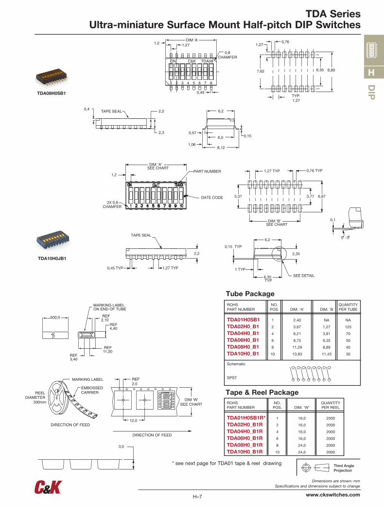
TDA SeriesUltra-miniature Surface Mount Half-pitch DIP Switches
TAPE SEAL0,4 2,2
2,3 0,57
1,068,12
0,15
6,2
6,0
7 8654321
ON TDA08C&K
0,8CHAMFER
1,2 1,27DIM 'A'
0,45
0,761,27
7,62 6,35 8,89
TYP.1,27
Tape & Reel Package
TDA08H0SB1
ROHS NO. QUANTITY PART NUMBER POS. DIM. ‘W’ PER REEL
TDA01H0SB1R* 1 16,0 2500
TDA02H0_B1R 2 16,0 2000
TDA04H0_B1R 4 16,0 2000
TDA06H0_B1R 6 16,0 2000
TDA08H0_B1R 8 24,0 2000
TDA10H0_B1R 10 24,0 2000
3,0
MARKING LABEL
EMBOSSEDCARRIER
DIRECTION OF FEED
REF2,0
DIM 'W'SEE CHART
12,0
REEL DIAMETER
330mm
1 2 3 4 5 6
ON
C&
K TDA
06
DIRECTION OF FEED
Tube Package
500,0
REF4,40
REF2,10
MARKING LABELON END OF TUBE
REF11,20
REF3,40
0 ~5
0,1
DIM ’A’SEE CHART
1,27 TYP
6,35TYP
6,973,77
1,27 TYP 0,76 TYP
6,2
2,35
DIM 'B'SEE CHART
1,2
0,45 TYP
2,2
5,37
1 TYP
0,15 TYP
2X 0,8CHAMFER
DATE CODE
PART NUMBER
TAPE SEAL
SEE DETAIL
TDA10H0JB1
* see next page for TDA01 tape & reel drawing

4.00 0.10 8.00 0.10
1.5
8.606.55
0.40 0.05
16.0 0.307.50 0.10
1.75 0.10
0.4
2.0 0.2TYP
14.0
330
8.60 0.16.55 0.1
1 0.1
2.9 0.1
R0.3MAX
2.90
2.65
2 0.5
13 0.521 0.8
+0.10-0.00
+0.2OSEE DTEAIL A
SEE DETAIL "B'
DETAIL "B"
DIP
H
H–8
Dimensions are shown: Inch (mm) Specifications and dimensions subject to change
www.ckswitches.com
TDA SeriesUltra-miniature Surface Mount Half-pitch DIP Switches
TDA01H0SB1R

DIP
H
H–9
Dimensions are shown: Inch (mm) Specifications and dimensions subject to change
www.ckswitches.com
SDA SeriesLow Profile DIP Switches
SpecificationsCONTACT RATING: 25 mA @ 24 V DC or 100 mA @ 5 V DC.
MECHANICAL AND ELECTRICAL LIFE: 1,000 cycles at rated loads.
CONTACT RESISTANCE: 50 mΩ max. initial.
INSULATION RESISTANCE: 100 MΩ between terminals.
DIELECTRIC WITHSTANDING VOLTAGE: 300 V DC min. for 1 min-ute.
STORAGE TEMPERATURE: -40°C to 85°C.
OPERATING TEMPERATURE: -40°C to 85°C.
OPERATING FORCE: 800 grams max.
SOLDERABILITY: Dip and look solderability testing per C&K spec. #448. Unplated edges of terminals permitted.
PACKAGING: Switches supplied in rigid dispensing tubes in full-tube quantities only, this may affect order quantity. Numbers of switches per tube varies with model. Tape and reel pack-
Features/Benefits• Low profile design saves space• Thru-hole and surface mount models• Tape and reel packaging available• RoHS compliant
aging also available for surface mount options.
MaterialsHOUSING: PPS, color black (UL94V-0).
COVER: PPS, color black (UL94V-0).
ACTUATOR: PA6T (UL94-0)
CONTACTS: Gold plated Beryllium copper.
TERMINALS: Gold plate over nickel plated brass.
TAPE SEAL: Polyimide.
Note: Specifications and materials listed above are for switches with standard options. For information on specific and custom switches, consult Customer Service Center. For Tin Lead options consult customer service center.
Typical Applications• Address switch for industrial
controls• Logic switching for computers
and peripherals• Function controlling for
numerous applications
How To OrderThe Build-A Switch concept allows you to mix and match options to create the switch you need. Below is a complete listing of options shown in catalog. To order, simply select desired option from each category and place in the appropriate box.
All switches supplied in “OFF” position.
Number ofPositionsSDA01SDA02SDA03SDA04SDA05SDA06SDA07SDA08SDA09SDA10 SDA12
ActuatorH0 FlushH1 Extended
TerminationsBlank Thru-holeS Gull wing
PackagingNONE Tubes R T/R
S D A B
Contact materialB Gold
H
SealedD NoneBlank Top tape seal
28 may 18

DIP
H
H–10
Dimensions are shown: Inch (mm) Specifications and dimensions subject to change
www.ckswitches.com
PEELABLETAPE SEAL
.183(4,65)
.100(2,54)
.010(0,25)
.024(0,61)
.063(1,60) .316
(8,03)
.295(7,49)
1 2 3 4 5 6 7 8
DIM 'A' .051(1,30)
.100 TYP.(2,54)
.300 TYP.(7,6)
Ø.031 TYP.(0,8)
.106(2,70)
TRAVEL
.138(3,5)
Flush Actuator – With Top Tape, Thru-hole Terminals
SDA SeriesLow Profile DIP Switches
SDA08H0B
NOTE: SDA 01 options are 4,25mm thick
1 2 3 4 5 6 7 8
DIM 'A'
.183(4,65) .106
(2,70)
.100(2,54)
.010(0,25)
.024(0,61)
.051(1,30)
.063(1,60) .316
(8,03)
.295(7,49)
.100(2,54)TYP.
.300 TYP.(7,6)Ø.031
(0,8)TYP.
TRAVEL
.238(3,5)
Flush Actuator – No Tape, Thru-hole Terminals
SDA08H0BD
ROHS NO. QUANTITYPART NUMBER POS. DIM. ‘A’ PER TUBE
SDA01H0BD 1 .178 (4,52) 100
SDA02H0BD 2 .278 (7,06) 60
SDA03H0BD 3 .378 (9,60) 45
SDA04H0BD 4 .476 (12,10) 35
SDA05H0BD 5 .578 (14,68) 30
SDA06H0BD 6 .676 (17,18) 25
SDA07H0BD 7 .778 (19,76) 20
SDA08H0BD 8 .876 (22,26) 20
SDA09H0BD 9 .978 (24,84) 15
SDA10H0BD 10 1.076 (27,34) 15
SDA12H0BD 12 1.279 (32,50) 14
Schematic
SPST
ROHS NO. QUANTITYPART NUMBER POS. DIM. ‘A’ PER TUBE
SDA01H0B 1 .178 (4,52) 100
SDA02H0B 2 .278 (7,06) 60
SDA03H0B 3 .378 (9,60) 45
SDA04H0B 4 .476 (12,10) 35
SDA05H0B 5 .578 (14,68) 30
SDA06H0B 6 .676 (17,18) 25
SDA07H0B 7 .778 (19,76) 20
SDA08H0B 8 .876 (22,26) 20
SDA09H0B 9 .978 (24,84) 15
SDA10H0B 10 1.076 (27,34) 15
SDA12H0B 12 1.279 (32,50) 14
Schematic
SPST
NOTE: SDA 01 options are 4,25mm thick
28 may 18

DIP
H
H–11
Dimensions are shown: Inch (mm) Specifications and dimensions subject to change
www.ckswitches.com
1 2 3 4 5 6 7 8
PEELABLETAPE SEAL
DIM 'A'
.100(2,54)
.031(0,79).024
(0,61)
.240 TYP.(6,10)
.059 MIN.(1,50)
.051(1,30)
.366(9,30)
.295(7,49)
.100(2,54)TYP.
.175(4,45)
.409 MIN.(10,4)TRAVEL
Flush Actuator – With Top Tape, Surface Mount Terminals
1 2 3 4 5 6 7 8
DIM 'A'
.100(2,54)
.031(0,79).024
(0,61)
.240 TYP.(6,10)
.059 MIN.(1,50)
.051(1,30)
.366(9,30)
.295(7,49)
.100(2,54)TYP.
.409 MIN.(10,4)
.175(4,45)
TRAVEL
.138(3,5)
Flush Actuator – No Tape, Surface Mount Terminals
SDA08H0SB
SDA08H0SBD
ROHS NO. QUANTITYPART NUMBER POS. DIM. ‘A’ PER TUBE
SDA01H0SB 1 .178 (4,52) 100
SDA02H0SB 2 .278 (7,06) 60
SDA03H0SB 3 .378 (9,60) 45
SDA04H0SB 4 .476 (12,10) 35
SDA05H0SB 5 .578 (14,68) 30
SDA06H0SB 6 .676 (17,18) 25
SDA07H0SB 7 .778 (19,76) 20
SDA08H0SB 8 .876 (22,26) 20
SDA09H0SB 9 .978 (24,84) 15
SDA10H0SB 10 1.076 (27,34) 15
SDA12H0SB 12 1.279 (32,50) 14
Schematic
SPST
ROHS NO. QUANTITYPART NUMBER POS. DIM. ‘A’ PER TUBE
SDA01H0SBD 1 .178 (4,52) 100
SDA02H0SBD 2 .278 (7,06) 60
SDA03H0SBD 3 .378 (9,60) 45
SDA04H0SBD 4 .476 (12,10) 35
SDA05H0SBD 5 .578 (14,68) 30
SDA06H0SBD 6 .676 (17,18) 25
SDA07H0SBD 7 .778 (19,76) 20
SDA08H0SBD 8 .876 (22,26) 20
SDA09H0SBD 9 .978 (24,84) 15
SDA10H0SBD 10 1.076 (27,34) 15
SDA12H0SBD 12 1.279 (32,50) 14
Schematic
SPST
NOTE: SDA 01 options are 4,25mm thick
NOTE: SDA 01 options are 4,25mm thick
1 2 3 4 5 6 7 8
DIM 'A'
.183(4,65)
.100(2,54)
.010(0,25)
.024(0,61)
.051(1,30)
.063(1,60) .316
(8,03)
.295(7,49)
.039(1,0)
.100 TYP.(2,54)
.047(1,2)
.300(7,6)TYP.
Ø.031TYP.(0,8)
.138(3,5)
TRAVEL
.039(1,0)
SDA SeriesLow Profile DIP Switches
Extended Actuator – No Top Tape, Thru-hole Terminals
SDA08H1BD
ROHS NO. QUANTITYPART NUMBER POS. DIM. ‘A’ PER TUBE
SDA01H1BD 1 .178 (4,52) 100
SDA02H1BD 2 .278 (7,06) 60
SDA03H1BD 3 .378 (9,60) 45
SDA04H1BD 4 .476 (12,10) 35
SDA05H1BD 5 .578 (14,68) 30
SDA06H1BD 6 .676 (17,18) 25
SDA07H1BD 7 .778 (19,76) 20
SDA08H1BD 8 .876 (22,26) 20
SDA09H1BD 9 .978 (24,84) 15
SDA10H1BD 10 1.076 (27,34) 15
SDA12H1BD 12 1.279 (32,50) 14
Schematic
SPST
NOTE: SDA 01 options are 4,25mm thick
28 may 18

DIP
H
H–12
Dimensions are shown: Inch (mm) Specifications and dimensions subject to change
www.ckswitches.com
SDA SeriesLow Profile DIP Switches
A A
A A
'W1'
10 16
'C'
'H'MAX3°
'B'
MAX3°
0.4
'D'
2 TYP 4 TYP 1.5 TYP
'W1'
1.75
'C'
1.5 TYP
'B'MAX3°
0.42
13
21
100330
3 TYP
'W2'
MODEL NO.'S' OPTION
DIM. 'H'(REF.)
DIM. 'W1'(REF.)
DIM. 'W2'(REF.)
DIM. 'B'(REF.)
DIM. 'C'(REF.)
DIM. 'D'(REF.)
QUANTITYPER REEL
SDA01 H0 5.2 24.0 24.4 8.5 11.5 N/A 1500H1 5.8 1450
SDA02 H0 4.8 24.0 24.4 7.9 11.5 N/A 750H1 5.8 700
SDA03 H0 4.8 24.0 24.4 10.4 11.5 N/A 750H1 5.8 700
SDA04 H0 4.8 24.0 24.4 12.9 11.5 N/A 750H1 5.8 700
SDA05 H0 4.8 24.0 24.4 15.4 11.5 N/A 750H1 5.8 700
SDA06 H0 4.8 32.0 32.4 18.0 14.2 28.4 750H1 5.8 700
SDA07 H0 4.8 32.0 32.4 20.5 14.2 28.4 750H1 NOT CURRENTLY AVAILABLE IN TAPE AND REEL
SDA08 H0 4.8 44.0 44.4 22.7 20.2 40.4 750H1 5.8 700
SDA09 H0 4.8 44.0 44.4 25.5 20.2 40.4 750H1 5.8 700
SDA10 H0 4.8 44.0 44.0 28.1 20.2 40.4 750H1 5.8 700
SDA12 H0 4.8 44.0 44.4 33.2 20.2 40.4 750H1 NOT CURRENTLY AVAILABLE IN TAPE AND REEL
6-12 OPTION SDA08 SHOWN
2-5 OPTION SDA04 SHOWN
DIRECTION OF FEED
DIRECTION OF FEED
REEL LAYOUTSCALE 1:4:1
SEE DETAIL A
SCALE 1:1:1ADETAIL
B-BSECTION
B-BSECTIONA-ASECTION
A
A
B B
"H"
2.5
"W1"
"C"
1.75 TYP1.5+0.1 02
4
8 TYP
0.4±0.05
"B"
MAX3°
5.3
TYP1.5+0.1 0
MAX3°
11
SDA01H1SBDR OPTION SHOWN
DIRECTION OF FEED
A-ASECTION
B-BSECTION
Tape & Reel Packaging – Surface Mount Options only
1 2 3 4 5 6 7 8
DIM 'A'
.100(2,54)
.031(0,79).024 TYP.
(0,61)
.240 TYP.(6,10)
.059 MIN.(1,50)
.051(1,30)
.366(9,30)
.100 TYP.(2,54)
.409 MIN.(10,4)
.051(1,30) .295
(7,49).039(1,0)
.175(4,45)
TRAVEL
.138(3,5)
Extended Actuator – No Top Tape, Surface Mount Terminals
SDA08H1SBD
ROHS NO. QUANTITYPART NUMBER POS. DIM. ‘A’ PER TUBE
SDA01H1SBD 1 .178 (4,52) 100
SDA02H1SBD 2 .278 (7,06) 60
SDA03H1SBD 3 .378 (9,60) 45
SDA04H1SBD 4 .476 (12,10) 35
SDA05H1SBD 5 .578 (14,68) 30
SDA06H1SBD 6 .676 (17,18) 25
SDA07H1SBD 7 .778 (19,76) 20
SDA08H1SBD 8 .876 (22,26) 20
SDA09H1SBD 9 .978 (24,84) 15
SDA10H1SBD 10 1.076 (27,34) 15
SDA12H1SBD 12 1.279 (32,50) 14
Schematic
SPSTNOTE: SDA 01 options are 4,25mm thick
28 may 18

DIP
H
H–13
Dimensions are shown: Inch (mm) Specifications and dimensions subject to change
www.ckswitches.com
SDB SeriesLow Profile DIP Switches
SpecificationsCONTACT RATING: 25 mA @ 24 V DC or 100 mA @ 5 V DC.
MECHANICAL AND ELECTRICAL LIFE: 1,000 cycles at rated loads.
CONTACT RESISTANCE: 50 mΩ max. initial.
INSULATION RESISTANCE: 1000 MΩ between terminals.
DIELECTRIC WITHSTANDING VOLTAGE: 300 V DC min. for 1 min-ute.
STORAGE TEMPERATURE: -40°C to 85°C.
OPERATING TEMPERATURE: -40°C to 85°C.
OPERATING FORCE: 8N max.
SOLDERABILITY: Dip and look solderability testing per C&K spec. #448. Unplated edges of terminals permitted.
PACKAGING: Switches supplied in rigid dispensing tubes in full-tube quantities only, this may affect order quantity. Numbers of switches per tube varies with model. Tape and reel pack-aging also available for surface mount options.
Features/Benefits• Low profile design saves space• Thru-hole and surface mount models• Tape and reel packaging available• Top tape seal options• New generation price competitive• RoHS compliant
MaterialsHOUSING: PA46, color black (UL94V-0).
COVER: PA46, color black (UL94V-0).
ACTUATOR: PA46, color white (UL94V-0).
CONTACTS: Gold plated phosphor bronze.
TERMINALS: Gold plate over nickel plated brass.
TAPE SEAL: PI with Silicon coated.
Note: Specifications and materials listed above are for switches with standard options. For information on specific and custom switches, consult Customer Service Center. For Tin Lead options consult customer service center.
Typical Applications• Address switch for industrial
controls• Logic switching for computers
and peripherals• Function controlling for
numerous applications
How To OrderThe Build-A Switch concept allows you to mix and match options to create the switch you need. Below is a complete listing of options shown in catalog. To order, simply select desired option from each category and place in the appropriate box.
All switches supplied in “OFF” position.Options for “ON” are available on volume demand.
Number ofPositionsSDB01SDB02SDB03SDB04SDB05SDB06SDB07SDB08SDB09SDB10 SDB12
ActuatorH0 FlushH1 Extended
TerminationsBlank Thru-holeS Gull wing
PackagingNONE Tubes R T/R
S D B B
Contact materialB Gold
H
SealedD NoneBlank Top tape seal
NEW
18 oct 18

DIP
H
H–14
Dimensions are shown: mm Specifications and dimensions subject to change
www.ckswitches.com
Flush Actuator – With Top Tape, Thru-hole Terminals
SDB SeriesLow Profile DIP Switches
SDB08H0B
1 2 3 4 5 6 7 8
NO K&C BDS
Flush Actuator – No Tape, Thru-hole Terminals
SDB08H0BD
ROHS NO. QUANTITYPART NUMBER POS. DIM. ‘A’ PER TUBE
SDB01H0BD 1 3.64 130
SDB02H0BD 2 6.18 77
SDB03H0BD 3 8.72 55
SDB04H0BD 4 11.26 42
SDB05H0BD 5 13.80 34
SDB06H0BD 6 16.34 29
SDB07H0BD 7 18.88 25
SDB08H0BD 8 21.42 22
SDB09H0BD 9 23.96 20
SDB10H0BD 10 26.50 18
SDB12H0BD 12 31.58 15
Schematic
SPST
1 2 3 4 5 6 7 8
NO K&C BDS
ROHS NO. QUANTITYPART NUMBER POS. DIM. ‘A’ PER TUBE
SDB01H0B 1 3.64 130
SDB02H0B 2 6.18 77
SDB03H0B 3 8.72 55
SDB04H0B 4 11.26 42
SDB05H0B 5 13.80 34
SDB06H0B 6 16.34 29
SDB07H0B 7 18.88 25
SDB08H0B 8 21.42 22
SDB09H0B 9 23.96 20
SDB10H0B 10 26.50 18
SDB12H0B 12 31.58 15
Schematic
SPST
htiw mlif IPdetaoc enociliS
1 2 3 4 5 6 7 8
NO K&C BDS
htiw mlif IPdetaoc enociliS
1 2 3 4 5 6 7 8
NO K&C BDS
NEW
18 oct 18

DIP
H
H–15
Dimensions are shown: mm Specifications and dimensions subject to change
www.ckswitches.com
Flush Actuator – With Top Tape, Surface Mount Terminals
Flush Actuator – No Tape, Surface Mount Terminals
SDB08H0SB
SDB08H0SBD
ROHS NO. QUANTITYPART NUMBER POS. DIM. ‘A’ PER TUBE
SDB01H0SB 1 3.64 130
SDB02H0SB 2 6.18 77
SDB03H0SB 3 8.72 55
SDB04H0SB 4 11.26 42
SDB05H0SB 5 13.80 34
SDB06H0SB 6 16.34 29
SDB07H0SB 7 18.88 25
SDB08H0SB 8 21.42 22
SDB09H0SB 9 23.96 20
SDB10H0SB 10 26.50 18
SDB12H0SB 12 31.58 15
Schematic
SPST
htiw mlif IPdetaoc enociliS
1 2 3 4 5 6 7 8
NO K&C BDS
ROHS NO. QUANTITYPART NUMBER POS. DIM. ‘A’ PER TUBE
SDB01H0SBD 1 3.64 130
SDB02H0SBD 2 6.18 77
SDB03H0SBD 3 8.72 55
SDB04H0SBD 4 11.26 42
SDB05H0SBD 5 13.80 34
SDB06H0SBD 6 16.34 29
SDB07H0SBD 7 18.88 25
SDB08H0SBD 8 21.42 22
SDB09H0SBD 9 23.96 20
SDB10H0SBD 10 26.50 18
SDB12H0SBD 12 31.58 15
Schematic
SPST1 2 3 4 5 6 7 8
NO K&C BDS
SDB SeriesLow Profile DIP Switches
Extended Actuator – No Top Tape, Thru-hole Terminals
SDB08H1BD
ROHS NO. QUANTITYPART NUMBER POS. DIM. ‘A’ PER TUBE
SDB01H1BD 1 3.64 130
SDB02H1BD 2 6.18 77
SDB03H1BD 3 8.72 55
SDB04H1BD 4 11.26 42
SDB05H1BD 5 13.80 34
SDB06H1BD 6 16.34 29
SDB07H1BD 7 18.88 25
SDB08H1BD 8 21.42 22
SDB09H1BD 9 23.96 20
SDB10H1BD 10 26.50 18
SDB12H1BD 12 31.58 15
Schematic
SPST1 2 3 4 5 6 7 8
NO K&C BDS
htiw mlif IPdetaoc enociliS
1 2 3 4 5 6 7 8
NO K&C BDS
1 2 3 4 5 6 7 8
NO K&C BDS
1 2 3 4 5 6 7 8
NO K&C BDS
NEW
18 oct 18

DIP
H
H–16
Dimensions are shown: mm Specifications and dimensions subject to change
www.ckswitches.com
SDB SeriesLow Profile DIP Switches
DIM "W1"(REF)
DIM "W2"(REF)
DIM "B"(REF)
DIM "D"(REF)
QUANTITYPER FEEL
H0
H1
H0
H1
H0
H1
H0
H1
H0
H1
H0
H1
H0
H1
H0
H1
H0
H1
H0
H1
H0
H1
MODEL NO."S" OPTION
SDB01
SDB12
SDB10
SDB02
SDB03
SDB04
SDB05
SDB06
SDB07
SDB08
SDB09
12
16
44 46
46
46
34
34
26
32
44
44
24
32
32
32
32
18
14
32.24
27.46
24.62
22.1
19.54
17.00
14.46
11.92
9.38
6.84
4.84
34
34
34
8.5
12.5
20.5
28.5
28.5
28.5
28.5
28.5
40.5
40.5
40.5 1000
1000
1000
1000
1000
1000
1000
1000
1000
1000
1000
Tape & Reel Packaging – Surface Mount Options only
Extended Actuator – No Top Tape, Surface Mount Terminals
SDB08H1SBD
ROHS NO. QUANTITYPART NUMBER POS. DIM. ‘A’ PER TUBE
SDB01H1SBD 1 3.64 130
SDB02H1SBD 2 6.18 77
SDB03H1SBD 3 8.72 55
SDB04H1SBD 4 11.26 42
SDB05H1SBD 5 13.80 34
SDB06H1SBD 6 16.34 29
SDB07H1SBD 7 18.88 25
SDB08H1SBD 8 21.42 22
SDB09H1SBD 9 23.96 20
SDB10H1SBD 10 26.50 18
SDB12H1SBD 12 31.58 15
Schematic
SPST1 2 3 4 5 6 7 8
NO K&C BDS
1 2 3 4 5 6 7 8
NO K&C BDS
NEW
18 oct 18
A-A NOITCES
B-B NOITCESDEEF FO NOITCERID
TUOYAL LEER01:1 ELACS
A LIATED EES
A LIATED1:1 ELACS
A-A NOITCES
B-B NOITCESDEEF FO NOITCERID
TUOYAL LEER01:1 ELACS
A LIATED EES
A LIATED1:1 ELACS

DIP
H
H–17
Dimensions are shown: Inch (mm) Specifications and dimensions subject to change
www.ckswitches.com
Dimensions are shown: Inch (mm) Specifications and dimensions subject to change
SpecificationsSWITCH FUNCTION: SPST - 2, 3, 4, 5, 6, 7, 8, 9, 10 & 12
positions
CONTACT RATING:
Carry: 100 mA @ 50 V DC max.
Switch: 0.1 mA @ 5 V DC min to 100 mA @ 25 V DC max.
MECHANICAL AND ELECTRICAL LIFE: 2,000 make-and-break cycles at full load, each circuit.
CONTACT RESISTANCE: Below 50 milliohms typ. initial
@ 2-4 V DC, 100mA.
INSULATION RESISTANCE: 109 ohms min.
DIELECTRIC STRENGTH: 500 V RMS min. @ sea level between adjacent terminals.
STORAGE TEMPERATURE: -40°C to 85°C.
OPERATING TEMPERATURE: -40°C to 85°C.
OPERATING FORCE: 100-700g inital.
SD SeriesLow Profile DIP Switches
PACKAGING: Thru-hole switches supplied in rigid dispensing tubes in full-tube quantities only: this may effect order quantity. Surface mount switches available in tape and reel packaging by added ‘R’ to end of part number; 1,000 pieces per reel. Switch position 1 denotes pin number 1. All switch actuators in ‘OFF’ position,
standard.
MaterialsCASE & COVER: (PPA), flame retardant (UL 94V-0)
ACTUATOR: Nylon, flame retardant (UL 94V-0)
CONTACTS: BeCu with gold plate.
TERMINALS: Bright tin-plated brass.
TERMINAL SEAL: All terminals insert molded.
TAPE SEAL: Polyimide.
Note: Specifications and materials listed above are for switches with standard options.
For information on specific and custom switches, consult Customer Service Center.
Features/Benefits• Low profile design saves space• Thru-hole and surface mount
models• Tape and reel packaging available• Sealed with top tape• RoHS compliant
Typical Applications• Address switch for industrial
controls• Logic switching for computers
and peripherals• Function controlling for
numerous applications
Numberof PositionsSD02 SD07SD03 SD08SD04 SD09SD05 SD10SD06 SD12
ActuatorH0 Flush Actuator “OFF” positionH1 Extended Actuator “OFF” positionH2 Flush Actuator “ON” positionH3 Extended Actuator “ON” position
TerminationsS Gull wing(None) PC ThruHole
Contact MaterialB Gold 10µ INB1 Gold 30µ IN *
* Consult factory for availability
Process Seal(None) Tape sealD No tape seal
Packaging(None) TubesR Tape and Reel
DS
How To OrderThe Build-A Switch concept allows you to mix and match options to create the switch you need. Below is a complete listing of options shown in catalog. To order, simply select desired option from each category and place in the appropriate box.
9 January 2018

DIP
H
1 8765432
ORIENTATION MARK
PEELABLETAPE SEAL
.300(7,62)
.390(9,91)
.010 TYP.(0,25)
STANDOFF
.027(0,70)ACTUATOR TRAVEL
.142(3,62)
.263(6,68)
DIM. 'A'SEE CHART
.315 TYP.(8,00)
.160(4,06)WITH TAPE
.100 TYP.(2,54).022 TYP.
(0,55)
.010 TYP.(0,25)
ON
.243 TYP.(6,17)
.044 MIN.(1,12)
.100(2,54)TYP.
.435 MIN.(11,05)
1 8765432
.010 TYP.(0,25)
.023 TYP.(0,60)STANDOFF
.027(0,70)ACTUATOR TRAVEL
.142(3,62)
.263(6,68)
DIM. 'A'SEE CHART
.325 TYP.(8,25)
.315 TYP.(8,00).168 TYP.
(4,30)
.126 TYP.(3,20)
.100 TYP.(2,54).022 TYP.
(0,55)
.059 TYP.(1,50)
H1 Actuator0.010 TYP.(0,25)
ON
PEELABLETAPE SEAL
ORIENTATION MARK
.100(2,54)TYP.
.300 TYP.(7,6)Ø.038
(0,97)TYP.
SD SeriesLow Profile DIP Switches
Sealed Flush Actuator – With Top Tape, Surface Mount Terminals
Sealed Extended Actuator – With Top Tape, Thru-hole Terminals RoHS NO. QUANTITYPART NUMBER POS. DIM. ‘A’ PER TUBE
SD02H1B 2 .258 (6,55) 85
SD03H1B 3 .358 (9,09) 60
SD04H1B 4 .458 (11,63) 45
SD05H1B 5 .558 (14,17) 40
SD06H1B 6 .658 (16,71) 30
SD07H1B 7 .758 (19,25) 25
SD08H1B 8 .858 (21,79) 25
SD09H1B 9 .958 (24,33) 20
SD10H1B 10 1.058 (26,87) 20
SD12H1B 12 1.258 (31,95) 15
Schematic
SPST
RoHS NO. QUANTITYPART NUMBER POS. DIM. ‘A’ PER TUBE
SD02H0SB 2 .258 (6,55) 85
SD03H0SB 3 .358 (9,09) 60
SD04H0SB 4 .458 (11,63) 45
SD05H0SB 5 .558 (14,17) 40
SD06H0SB 6 .658 (16,71) 30
SD07H0SB 7 .758 (19,25) 25
SD08H0SB 8 .858 (21,79) 25
SD09H0SB 9 .958 (24,33) 20
SD10H0SB 10 1.058 (26,87) 20
SD12H0SB 12 1.258 (31,95) 15
Schematic
SPST
Sealed Flush Actuator – With Top Tape, Thru-hole TerminalsProcess sealed - withstands soldering and cleaning processes
1 8765432
.010 TYP.(0,25)
.023 TYP.(0,60)STANDOFF
.027(0,70)ACTUATOR TRAVEL
.142(3,62)
.263(6,68)
DIM. 'A'SEE CHART
.325 TYP.(8,25)
.315 TYP.(8,00)
.168 TYP.(4,27)
.126 TYP.(3,20)
.100 TYP.(2,54).022 TYP.
(0,55)
.059 TYP.(1,50)
ON
PEELABLETAPE SEAL
ORIENTATION MARK
.100(2,54)TYP.
.300 TYP.(7,6)Ø.038
(0,97)TYP.
ROHS NO. QUANTITYPART NUMBER POS. DIM. ‘A’ PER TUBE
SD02H0B 2 .258 (6,55) 85
SD03H0B 3 .358 (9,09) 60
SD04H0B 4 .458 (11,63) 45
SD05H0B 5 .558 (14,17) 40
SD06H0B 6 .658 (16,71) 30
SD07H0B 7 .758 (19,25) 25
SD08H0B 8 .858 (21,79) 25
SD09H0B 9 .958 (24,33) 20
SD10H0B 10 1.058 (26,87) 20
SD12H0B 12 1.258 (31,95) 15
Schematic
SPST
H–18
Dimensions are shown: Inch (mm) Specifications and dimensions subject to change
www.ckswitches.com
Table applicable to “H0” and “H2” actuator options.
Table applicable to “H1” and “H3” actuator options.
Table applicable to “H0” and “H2” actuator options.
9 January 2018

DIP
H
H–19
Dimensions are shown: Inch (mm) Specifications and dimensions subject to change
www.ckswitches.com
TAPE & REEL PACKAGING – SURFACE MOUNT OPTIONS ONLY
SD SeriesLow Profile DIP Switches
FEED DIRECTION
DIM ‘D’SEE CHART
DIM ‘C’SEE CHART
DIM ‘G’SEE CHART
.069(1,75)
DIM ‘P’SEE CHART
.061 DIA(1,55)
DIM ‘B’SEE
CHART
.079(2,00)
.057(4,00)
DIM ‘A’SEE CHART ELONGATED HOLES ON
SD07-SD12 ONLY
SWITCH NO.
DIM ’A’POCKETLENGTH
@ BOTTOM
DIM ’B’POCKETLENGTH
@ BOTTOM
DIM ’C’TAPE
WIDTH
DIM ’D’POCKETDEPTH
DIM ’G’SPROCKET
HOLESPACING
DIM ’P’PITCH
BETWEENPOCKETS
SD02SD03SD04SD05SD06SD07SD08SD09SD10SD12
.472(12,0)
.472(12,0)
.472(12,0)
.472(12,0)
.472(12,0)
.472(12,0)
.472(12,0)
.472(12,0)
.472(12,0)
.472(12,0)
.177(4,5)
.177(4,5)
.177(4,5)
.177(4,5)
.177(4,5)
.177(4,5)
.177(4,5)
.177(4,5)
.177(4,5)
.177(4,5)
N/AN/AN/AN/AN/A
1.118(28,4)1.591(40,4)1.591(40,4)1.591(40,4)1.591(40,4)
.413(10,5)
.406(10,3)
.429(10,9)
.406(10,3)
.406(10,3)
.406(10,3)
.406(10,3)
.406(10,3)
.406(10,3)
.406(10,3)
.630(16,0)
.630(16,0)
.954(24,0)
.954(24,0)
.954(24,0)1.260(32,0)1.732(44,0)1.732(44,0)1.732(44,0)1.732(44,0)
.315(8,0).406(10,3).476(12,1).602(15,3).701(17,8).803(20,4).854(21,7)1.028(26,1)1.055(26,8)1.303(33,1)
Reel Information
Outside diameter 13.00 (333,0)Pilot hole .512 (13,0)
RoHS NO. QUANTITYPART NUMBER POS. DIM. ‘A’ PER REEL
SD02H0SBR 2 .258 (6,55) 1000
SD03H0SBR 3 .358 (9,09) 1000
SD04H0SBR 4 .458 (11,63) 1000
SD05H0SBR 5 .558 (14,17) 1000
SD06H0SBR 6 .658 (16,71) 1000
SD07H0SBR 7 .758 (19,25 1000
SD08H0SBR 8 .858 (21,79) 1000
SD09H0SBR 9 .958 (24,33) 1000
SD10H0SBR 10 1.058 (26,87) 1000
SD12H0SBR 12 1.258 (31,95) 1000
Schematic
SPST
1 8765432
ORIENTATION MARK
PEELABLETAPE SEAL
.300(7,62)
.390(9,91)
.010 TYP.(0,25)
STANDOFF
.027(0,70)ACTUATOR TRAVEL
.142(3,62)
.263(6,68)
DIM. 'A'SEE CHART
.315 TYP.(8,00)
.170(4,31)WITH TAPE
.100 TYP.(2,54).022 TYP.
(0,55)
.010 TYP.(0,25)
.243 TYP.(6,17)
.044 MIN.(1,12)
.100(2,54)TYP.
.435 MIN.(11,05)
ON
H1 Actuator0.010 TYP.(0,25)
Sealed Extended Actuator – With Top Tape, Surface Mount Terminals
RoHS NO. QUANTITYPART NUMBER POS. DIM. ‘A’ PER TUBE
SD02H1SB 2 .258 (6,55) 85
SD03H1SB 3 .358 (9,09) 60
SD04H1SB 4 .458 (11,63) 45
SD05H1SB 5 .558 (14,17) 40
SD06H1SB 6 .658 (16,71) 30
SD07H1SB 7 .758 (19,25 25
SD08H1SB 8 .858 (21,79) 25
SD09H1SB 9 .958 (24,33) 20
SD10H1SB 10 1.058 (26,87) 20
SD12H1SB 12 1.258 (31,95) 15
Schematic
SPST
Table applicable to “H1” and “H3” actuator options.
Table applicable to “H0” and “H2” actuator options.
9 January 2018

DIP
H
H–20
Dimensions are shown: Inch (mm) Specifications and dimensions subject to change
www.ckswitches.com
Specifications
SWITCH FUNCTION: SPST - 1 thru 12 position available
(except 11 position).
CONTACT RATING:
Carry: 100 mA max. @ 50 V DC.
Switch: 100 mA max. @ 5 V DC or 25 mA max. @ 25 V DC.
MECHANICAL AND ELECTRICAL LIFE: 10,000 make-and-break cycles at full load, each circuit.
CONTACT RESISTANCE: Below 50 milliohms typ. initial
@ 2-4 V DC 100mA.
INSULATION RESISTANCE: 109 ohms min.
DIELECTRIC STRENGTH: 500 V RMS min. @ sea level between adjacent terminals.
CAPACITANCE: 5pF max. between adjacent terminals.
STORAGE & OPERATING TEMPERATURE: -40°C to 85°C.
SHOCK: Withstands 20g 11 ms sawtooth waveform with no con-tact opening greater than 10 microseconds.
QUANTITYPART NUMBER NO.POS. DIM. ‘A’ DIM. ‘B’ PER TUBE
BD01 1 .180 (4,57) NA 115
BD02 2 .280 (7,11) .100 (2,54) 74
BD03 3 .380 (9,65) .200 (5,08) 54
BD04 4 .480 (12,19) .300 (7,62) 43
BD05 5 .580 (14,73) .400 (10,16) 35
BD06 6 .680 (17,27) .500 (12,75) 30
BD07 7 .780 (19,81) .600 (15,24) 26
BD08 8 .880 (22,35) .700 (17,78) 23
BD09 9 .980 (24,89) .800 (20,32) 21
BD10 10 1.080 (27,43) .900 (22,.86) 19
BD12 12 1.280 (32,51) 1.100 (27,94) 16
Schematic
SPST
BD SeriesStandard Profile DIP Switches
VIBRATION: No contact opening greater than 10 microseconds and no contact closure when exposed to vibration .06 in DA or 5g, which-ever is less, from 10 to 55 Hz, and 10g from 55 to 500 Hz.
SOLDERABILITY: Per MIL-STD-202F method 208D, or EIA RS-186E method 9 (1 hour steam aging).
PACKAGING: Switches supplied in rigid dispensing tubes in full-tube quantities only: this may effect order quantity. Number of switches per tube varies with model. Switch position 1 denotes pin number 1. All switch actuators in ‘OFF’ position, standard.
MaterialsCASE & COVER: Glass filled polyester (PBT),
flame retardant (UL 94V-0).
ACTUATOR: Glass filled nylon 6/6, flame retardant,
heat stabilized (UL 94V-0)
CONTACTS: Gold over nickel over phosphor bronze.
TERMINALS: Matte-tin over nickel over phosphor bronze.
Note: Specifications and materials listed above are for switches with standard options. For information on specific and custom switches, consult Customer Service Center.
Features/Benefits• Traditional full profile DIP switch• Extended actuator for easy actuation• Open bottom construction allows for
solder washing without the need for tape seal
• RoHS compliant
Vertical Full Profile DIP
BD08
.030(0,77)
.160 TYP.(4,06)
.006(0,16)
.380(9,65)
.100 TYP.(2,54)
.020 TYP.(0,51)
.265(6,73)
.141 TYP.(3,58)
.089(2,26)
.297(7,55)
Ø.038 TYP.(0,97)
.100 TYP.(2,54)DIM 'A'
DIM 'B'
.297(7,55)
.032(0,82)TYP.
.080 TYP.(2,03)
1 2 3 4 5 6 7 8
ON
.062(1,58) MAXACTUATOR
TRAVEL
(1,5).059 TYP.
Typical Applications• Address switch for industrial controls• Logic switching for computers and peripherals• Function controlling for
numerous applications

DIP
H
H–21
Dimensions are shown: Inch (mm) Specifications and dimensions subject to change
www.ckswitches.com
8764321
ON
0.050(1,27)
.089(2,26)
0.061 TYP.(1,55)
0.030(0,77)
0.297(7,55)
.100(2,54)
.020 TYP.(0,51) .100 TYP.
(2,54)
.010(0,25).006
(0,16)
DIM.A
.380(9,65)
.046 DIA TYP.(1,17ø)
.100(2,54)
.100 TYP.(2,54)
.080(2,03)
.032(0,82)TYP.
5
.320(8,12)
.125(3,18)
QUANTITYPART NUMBER NO.POS. DIM. ‘A’ PER TUBE
BD02AV 2 .280 (7,11) 72
BD03AV 3 .380 (9,65) 52
BD04AV 4 .480 (12,19) 42
BD05AV 5 .580 (14,73) 35
BD06AV 6 .680 (17,27) 29
BD07AV 7 .780 (19,81) 26
BD08AV 8 .880 (22,35) 23
BD09AV 9 .980 (24,89) 20
BD10AV 10 1.080 (27,43) 18
BD12AV 12 1.280 (32,51) 15
Schematic
SPST
BD SeriesStandard Profile DIP Switches
Open Base and AV Right Angle Terminal Style
Installation, Soldering and CleaningAll BD Series Standard Profile DIP Switches can be hand soldered or machine soldered without the use of boot, caps, tapes or special attention. Open base washable models have unique design, allowing solvent cleaners and water/detergent solutions to flush and clean the electrical contacts of the contaminants and fluxes. For best results, follow these directions:
1) Wave soldering recommended at 500° F (260ºC) solder temperature.2) Hand solder using 30 watt small tip iron controlled at 500° F (260ºC), 10 seconds max./terminal.3) Open base washable models: Clean flux using forced rinse, high agitation or triple bath cleaning method. DO NOT mask or cover switch in any way during cleaning. Switch is designed for easy solvent flush out.4) All switch actuators must be in ‘OFF’ position during soldering and cleaning processes.
BD08AV

DIP
H
H–22
Dimensions are shown: Inch (mm) Specifications and dimensions subject to change
www.ckswitches.com
Specifications
SWITCH FUNCTION: SPST - 2 thru 12 position available
(except 11 position).
CONTACT RATING:
Carry: 100 mA max. @ 50 V DC.
Switch: 100 mA max. @ 5 V DC or 25 mA max. @ 25 V DC.
MECHANICAL AND ELECTRICAL LIFE: 10,000 make-and-break cycles at full load, each circuit.
CONTACT RESISTANCE: Below 50 milliohms typ. initial
@ 2-4 V DC 100mA.
INSULATION RESISTANCE: 109 ohms min.
DIELECTRIC STRENGTH: 300 V RMS min. @ sea level between adjacent terminals.
CAPACITANCE: 5pF max. between adjacent terminals.
STORAGE & OPERATING TEMPERATURE: -40°C to 85°C.
SHOCK: Withstands 20g 11 ms sawtooth waveform with no con-tact opening greater than 10 microseconds.
QUANTITYPART NUMBER NO.POS. DIM. ‘A’ DIM. ‘B’ PER TUBE
BDB02 2 .280 (7,11) .100 (2,54) 70
BDB03 3 .380 (9,65) .200 (5,08) 51
BDB04 4 .480 (12,19) .300 (7,62) 40
BDB05 5 .580 (14,73) .400 (10,16) 33
BDB06 6 .680 (17,27) .500 (12,75) 28
BDB07 7 .780 (19,81) .600 (15,24) 24
BDB08 8 .880 (22,35) .700 (17,78) 21
BDB09 9 .980 (24,89) .800 (20,32) 19
BDB10 10 1.080 (27,43) .900 (22,.86) 17
BDB12 12 1.280 (32,51) 1.100 (27,94) 14
Schematic
SPST
1 2 3 4 5 6 7 8
NO BDB
DATE CODE: YEAR+WEEKYEAR: The letter «A» means 2009, «B» means 2010..., «J» means 2018, and so onWEEK: «01» means the �rst week «01» means the second week, and so on
BDB SeriesStandard Profile DIP Switches
VIBRATION: No contact opening greater than 10 microseconds and no contact closure when exposed to vibration .06 in DA or 5g, which-ever is less, from 10 to 55 Hz, and 10g from 55 to 500 Hz.
SOLDERABILITY: Per MIL-STD-202F method 208D, or EIA RS-186E method 9 (1 hour steam aging).
PACKAGING: Switches supplied in rigid dispensing tubes in full-tube quantities only: this may effect order quantity. Number of switches per tube varies with model. Switch position 1 denotes pin number 1. All switch actuators in ‘OFF’ position, standard. 2. Option for “ON” is available on volume demand.
MaterialsHOUSING: PA46, color red (UL94V-0)
COVER: Glass filed polyester (PBT) (UL94V-0)
ACTUATOR: Glass filed polyester (PBT) (UL94V-0)
CONTACTS: Gold plate phosphor bronze
TERMINALS: Gold plate over nickel plated brass
Note: Specifications and materials listed above are for switches with standard options. For information on specific and custom switches, consult Customer Service Center.
Features/Benefits• Traditional full profile DIP switch• Extended actuator for easy actuation• Special sealed construction allows for
solder washing without the need for tape seal
• RoHS compliant• New generation price competitive
Vertical Full Profile DIP
BDB08
1 2 3 4 5 6 7 8
NO BDB
DATE CODE: YEAR+WEEKYEAR: The letter «A» means 2009, «B» means 2010..., «J» means 2018, and so onWEEK: «01» means the �rst week «01» means the second week, and so on
Typical Applications• Address switch for industrial controls• Logic switching for computers and peripherals• Function controlling for
numerous applications
21 aug 2018
NEW

DIP
H
H–23
Dimensions are shown: Inch (mm) Specifications and dimensions subject to change
www.ckswitches.com
BDB SeriesStandard Profile DIP Switches
Installation, Soldering and CleaningAll BDB Series Standard Profile DIP Switches can be hand soldered or machine soldered without the use of boot, caps, tapes or special attention. Open base washable models have unique design, allowing solvent cleaners and water/detergent solutions to flush and clean the electrical contacts of the contaminants and fluxes. For best results, follow these directions:
1) Wave soldering recommended at 500° F (260ºC) solder temperature.2) Hand solder using 30 watt small tip iron controlled at 500° F (260ºC), 10 seconds max./terminal.3) Open base washable models: Clean flux using forced rinse, high agitation or triple bath cleaning method. DO NOT mask or cover switch in any way during cleaning. Switch is designed for easy solvent flush out.4) All switch actuators must be in ‘OFF’ position during soldering and cleaning processes.
21 aug 2018
NEW

DIP
H
H–24
Dimensions are shown: Inch (mm) Specifications and dimensions subject to change
www.ckswitches.com
SpecificationsSWITCH FUNCTION: 1 thru 10 and 12 position available.
CONTACT RATING: 100 mA max. @ 5 V DC or 25 mA max. @ 24 V DC.
MECHANICAL AND ELECTRICAL LIFE: 1,000 cycles min. @ 5 V DC 10mA.
CONTACT RESISTANCE: 50 milliohms initial max.
INSULATION RESISTANCE: 100 V DC 100 megohms min.
DIELECTRIC WITHSTAND VOLTAGE: 300 V AC for 1 minute.
STORAGE TEMPERATURE: -40°C to 85°C.
OPERATING TEMPERATURE: -20°C to 85°C.
OPERATING FORCE: 800 grams max.
SOLDERABILITY: Flow solderable and washable (soldering: 260°C for 10 sec. max.)
PACKAGING: Switches supplied in rigid dispensing tubes in full-tube quantities only, this may affect order quantity. Numbers of switches per tube varies with model. Tape and reel packaging available for SMT options.
MaterialsHOUSING: PPS, color black (UL94V-0).COVER: PPS, color black (UL94V-0).ACTUATOR: PA-6T (UL94V-0).
CONTACTS: Beryllium Copper with Gold over Nickel plate.
TERMINALS: Brass, Gold over Nickel plate.
Note: Specifications and materials listed above are for switches with standard options. For information on specific and custom switches, consult Customer Service Center.
BPA SeriesSide Actuated DIP Switches
Features/Benefits• Side actuated contacts• Available in thru-hole or
SMT models• High pressure contact system does
not require tape seal for washing• RoHS compliant & compatible
Typical Applications• Address switch for industrial controls• Logic switching for computers and
peripherals• Function controlling for numerous
applications
ModelBPA01 1 positionBPA02 2 positionsBPA03 3 positionsBPA04 4 positionsBPA05 5 positionsBPA06 6 positionsBPA07 7 positionsBPA08 8 positionsBPA09 9 positionsBPA10 10 positionsBPA12 12 positions
On PositionNONE Down R Up Terminations
NONE PCS Gull wing
PackagingNONE Tube R Tape and Reel (Surface Mount only)
B P A B
Contact materialB BeCu, Gold over nickel plate
How To OrderThe Build-A Switch concept allows you to mix and match options to create the switch you need. Below is a complete listing of options shown in catalog. To order, simply select desired option from each category and place in the appropriate box.
All switches supplied in “OFF” position.
13 feb 19

DIP
H
H–25
Dimensions are shown: Inch (mm) Specifications and dimensions subject to change
www.ckswitches.com
ROHS NO. QUANTITYPART NUMBER POS. DIM. ‘A’ DIM. ‘B’ PER TUBE
BPA01SB 1 .176 (4,48) N/A 100
BPA02SB 2 .276 (7,0) .100 (2,54) 60
BPA03SB 3 .376 (9,6) .200 (5,08) 45
BPA04SB 4 .476 (12,1) .300 (7,62) 35
BPA05SB 5 .575 (14,6) .400 (10,16) 30
BPA06SB 6 .677 (17,2) .500 (12,70)) 25
BPA07SB 7 .776 (19,7) .600 (15,24) 20
BPA08SB 8 .878 (22,3) .700 (17,78) 20
BPA09SB 9 .976 (24,8) .800 (20,32) 15
BPA10SB 10 1.075 (27,3) .900 (22,86) 15
BPA12SB 12 1.280 (32,5) 1.100 (27,94) 14
Schematic
SPST
BPA SeriesSide Actuated DIP Switches
Side Actuator – Surface Mount Terminals
BPA08SB
NOTE: Tape and reel packaging available by adding “R” to end of project number.
ON
0.100(2,54)PITCH
0.236(6,0)
0.033/0.041(0,85/1,04)
0.063
0.024(1,6+0/-0,2)
(0,6+0/-0,1)
1 2 3 4 5 6 7 8
C&K BPA08
0.055(1,4)
5B
0.083(2,1)
0.029(0,75)
0.173(4,4)
0.321(8,15)
0.039(1,0)
0.366
250
“A”“B”
0.031(0,8)
0.010(0,25)
1 2 3 4 5 6 7 8
0.031(0,8)
(9,3)
6.11 10.41
2.54 TYP 1.52 MINTYP
"B"SEE CHART
P.C. MOUNTING
Side Actuator – Thru-hole Terminals
BPA08B
NOTE: Reverse throw available, contact C&K for P/N and quote.
ROHS NO. QUANTITYPART NUMBER POS. DIM. ‘A’ DIM. ‘B’ PER TUBE
BPA01B 1 .176 (4,48) N/A 100
BPA02B 2 .276 (7,0) .100 (2,54) 60
BPA03B 3 .376 (9,6) .200 (5,08) 45
BPA04B 4 .476 (12,1) .300 (7,62) 35
BPA05B 5 .575 (14,6) .400 (10,16) 30
BPA06B 6 .677 (17,2) .500 (12,70)) 25
BPA07B 7 .776 (19,7) .600 (15,24) 20
BPA08B 8 .878 (22,3) .700 (17,78) 20
BPA09B 9 .976 (24,8) .800 (20,32) 15
BPA10B 10 1.075 (27,3) .900 (22,86) 15
BPA12B 12 1.280 (32,5) 1.100 (27,94) 14
Schematic
SPST
1 2 3 4 5 6 7 8ON
0.100(2,54)PITCH
+.000-.008
+.000-.004
0.236(6,0)
0.051(1,3)
0.157(4,0)
0.106(2,7)
0.063
0.024
(1,6+0/-0,2)
(0,6+0/-0,2)
1 2 3 4 5 6 7 8
C&K BPA08
0.055(1,4)
5B
0.083(2,1)
0.029(0,75)0.173
(4,4)
0.321(8,15)
0.039(1,0)
0.010(0,25)
0.299/0.343(7,6/8,7)
250
“A”
“B”0.100(2,54)
0.300(7,6)
+.008-.000ø0.032
(0,8+0,2/-0)
“B”
13 feb 19

SEEDETAIL A
DIM. 'A'
DIM. 'C'
3x1200
400
ø7.48ø(190,0)
ø.512ø(13,0)
ø.827ø(21,0)
13.0(330)
3.937(100,0)
DIM. 'E'
2 x .079 (2P-7P)(2 x 2.0)2 x .118 (8P-10P)(2 x 3.0)
.079(2,00)
.079(2,00)
.069(1,75)
0.020(0,5)
.157(4,00)
.450(11,5)
.630(16,0)
.315(8,00)
30
MAX.
30 MAX.
DIM 'D'
Ø.012(0,30)MAX.
Ø.059(1,50)
Ø.012(0,30)MAX.
Ø.012(0,30)MAX.
.630(16,0)
0.020(0,5)
30
MAX.
DIM 'D'
DIM. 'A'
.079(2,00)
.069(1,75)
.157(4,00) Ø.059
(1,50)
DIM. 'B'
DIM. 'C'
.450(11,5)
.315(8,00)
30 MAX.
FEED DIRECTION
12
34
56
78
12
34
FEED DIRECTION
2 0.1 TYP
4 0.1 TYP
1.5+0.1 0 TYP
11.5 0.1
1.75 0.1
24 0.3 13.45 9.15
8 0.05
5.3 0.1 2.5 0.1
3 MAX
3 MAX
16 TYP
1.5 TYP
FEED DIRECTION
DIP
H
H–26
Dimensions are shown: Inch (mm) Specifications and dimensions subject to change
www.ckswitches.com
Tape & Reel Packaging – Surface Mount Options Only
Note: For tape and reel packaging, add ‘R’ to end of part number.
fix-mjc
MARKING LABEL ONEND OF TUBE 19.68 ± 0.04
(500,0 ± 1,0)
0.512(13,0)
0.512(13,0)
0.079(2,0)
0.020(0,5)
0.197(5,0)0.433(11,0)
0.177(4,5)
0.256(6,5)0.276 ± .008
(7,0 ± 0,2)
0.071(1,8)
0.079 REF.(2,0)
0.020 MAX.(0,5) TYP
Tube Packaging
BPA SeriesSide Actuated DIP Switches
2, 3, 4 & 5 Positions
6, 7, 8, 9, 10 & 12 Positions
POLES DIM. ‘A’ DIM. ‘B’ DIM. ‘C’ DIM. ‘D’ DIM. ‘E’
1 .453 (11,5) –– .945 (24,0) .530 (13,45) .960 (24,4)2 .453 (11,5) –– .945 (24,0) .311 (7,9) .960 (24,4)3 .453 (11,5) –– .945 (24,0) .409 (10,4) .960 (24,4)4 .453 (11,5) –– .945 (24,0) .508 (12,9) .960 (24,4)5 .453 (11,5) –– .945 (24,0) .606 (15,4) .960 (24,4)6 .559 (14,2) 1.118 (28,4) 1.260 (32,0) .709 (18,0) 1.275 (32,4)7 .559 (14,2) 1.118 (28,4) 1.260 (32,0) .807 (20,5) 1.275 (32,4)8 .795 (20,2) 1.590 (40,4) 1.732 (44,0) .894 (22,7) 1.748 (44,4)9 .795 (20,2) 1.590 (40,4) 1.732 (44,0) 1.004 (25,5) 1.748 (44,4)
10 .795 (20,2) 1.590 (40,4) 1.732 (44,0) 1.106 (28,1) 1.748 (44,4)12 .795 (20,2) 1.590 (40,4) 1.732 (44,0) 1.311 (33,3) 1.748 (44,4)
500500500500500500500500500500500
QTY/REEL
1 Position
13 feb 19

DIP
H
H–27
Dimensions are shown: Inch (mm) Specifications and dimensions subject to change
www.ckswitches.com
TDD SeriesJumper Switch
SpecificationsCONTACT RATING: 25 mA @ 24 V DC (switching) or
100 mA @ 50 V DC (steady state).
MECHANICAL AND ELECTRICAL LIFE: 200 cycles at rated loads.
CONTACT RESISTANCE: 100 mΩ max. initial. @ 2 V DC /10 mA
INSULATION RESISTANCE: 100 MΩ @ 100 V DC min.
DIELECTRIC STRENGTH: 300 V AC /minute
STORAGE TEMPERATURE: -40°C to 85°C.
OPERATING TEMPERATURE: -30°C to 85°C.
OPERATING FORCE: 4.9 N max.
SOLDERABILITY: Per MIL-STD-202F method 208D, or
EIA RS-186E method 9 (1 hour steam aging).
PACKAGING: 1,000 pieces tape & reel
Features/Benefits• Bifurcated contact for increased
electrical reliability• Process sealed for surface
mount soldering and washable processing
• RoHS compliant
MaterialsCASE AND COVER: PPS, color black (UL94V-0).
ACTUATOR: LCP (UL94-0)
CONTACTS: Copper alloy with gold plate over nickel plate
TERMINALS (INSERT MOLDED): Copper alloy gold flash over nickel plate
TAPE SEAL: Polyamide
Note: Specifications and materials listed above are for switches with standard options. For information on specific and custom switches, consult Customer Service Center. For Tin Lead options consult customer service center.
Typical Applications• Hand-held electronic devices• Portable computer and
electronic devices• Instrumentation and controls• Inverters
How To OrderThe Build-A Switch concept allows you to mix and match options to create the switch you need. Below is a complete listing of options shown in catalog. To order, simply select desired option from each category and place in the appropriate box.
All switches supplied in “OFF” position..
SeriesActuatorH0 Flush
TerminationsS Gull wing
PackagingR T/R
T D D B
Contact materialB Gold
H 0
Sealed1 Top tape seal
0 1 S 1 R

A
A
B B
213
2.1
120°
190
2X 0.2
16.4
33080
2
6,5R0,3 MAX
R0,3
0,35 THK
8 TYP
DRAFT3°
16
7,5
1,75
2,65
4,14,1
5
2
6,5
DRAFT3°
3,2 REF
1,5
1,54
DETAIL "B"
DETAIL B
DIRECTION OF FEED
REELNOT TO SCALE
SEE DETAIL AA-ASECTION
B-BSECTION
SCALE 6:1ADETAIL
DIP
H
H–28
Dimensions are shown: Inch (mm) Specifications and dimensions subject to change
www.ckswitches.com
TDD SeriesJumper Switch
2,2±0,1 (2,3)3X 0,15
0,300,054,2±0,5
3X 0,4
2,4
2X 0,4
2,65,2
3,5 3X 1
3X 0,6
6±0,3
5,8±0,5
1±0,1
3,5
3X 1,3
0,55 STROKE 0,55 STROKE
6±0,5
SCHEMATICSPDT
(C)
(1) (2)
(C)
(1)
(2)PCB LAYOUT
A-ASECTION

DIP
H
H–29
Dimensions are shown: Inch (mm) Specifications and dimensions subject to change
www.ckswitches.com
SpecificationsCONTACT RATING: Carry: 10 mA @ 5VDC Switching: 0.1 mA @ 0.1m VDC min.
MECHANICAL AND ELECTRICAL LIFE: 1,000 cycles min.
CONTACT RESISTANCE: 50 mΩ max. @ 20 V DC 10mA.
INSULATION RESISTANCE: 100 MΩ min. @ 100 V DC.
DIELECTRIC STRENGTH: 1 minute @ 300 V AC.
CAPACITANCE: 5pF max. between adjacent terminals.
OPERATING TEMPERATURE: -30°C to 60°C.
STORAGE TEMPERATURE: -30°C to 80°C.
OPERATING FORCE: 5.9N max.
SOLDERABILITY: Dip & look solderability testing per C&K spec. #448. Unplated edges of terminals permitted.
PACKAGING: Switches supplied in rigid dispensing tubes in full-tube quantities only, this may affect order quantity. Numbers of switches per tube varies with model.
MaterialsBASE: PPS (UL94V-0).COVER: PBT (UL94V-0).
ACTUATOR: 4/6 Nylon (UL 94V-0).
MOVABLE CONTACT: Beryllium copper alloy, gold over nickel plate.
FIXED CONTACT: Copper alloy, gold over nickel plate.
CLIP: Phosphor bronze wire. Phosphor bronze, Tin over nickel plate.
Note: Specifications and materials listed above are for switches with standard options. For information on specific and custom switches, consult Customer Service Center.
SPA SeriesSingle In-line Package Switches
Features/Benefits• Thin Single In-line Packaging saves
PCB space• Retention feature holds part to PCB
prior to soldering• Available in vertical or right angle
models• High pressure contact system
does not require tape sealing• RoHS compliant
Typical Applications• Address switch for industrial
controls• Logic switching for computers
and peripherals• Function controlling for
numerous applications
How To OrderThe Build-A Switch concept allows you to mix and match options to create the switch you need. Below is a complete listing of options shown in catalog. To order, simply select desired option from each category and place in the appropriate box.
All switches supplied in “OFF” position.
Number ofPositionsSPA02 2 positionsSPA04 4 positionsSPA06 6 positionsSPA08 8 positionsSPA10 10 positions
TerminationsNONE VerticalA Right Angle
Contact materialB Gold
S P A B
19 dec 17

1 2 3 4 5 6 7 8 C
1.8
0.25
0.7
1
0.7
3.2±0.3
DIM "A" 0,2SEE CHART
2.58 TYP
0.3 TYP
0.5 TYP
3.6±0.2
1.6±0.1
DIM "B"SEE CHART
2.54 TYP
0.9±0.1
DIM "B"SEE CHART
2.5 TYP 0.8 TYP6.2±0.1
STANDARD MARKING
C
PCB MOUNTING FOOTPRINT
DIP
H
H–30
Dimensions are shown: Inch (mm) Specifications and dimensions subject to change
www.ckswitches.com
1 2 3 4 5 6 7 8
.100(2,54)
.035(0,9)
.125(3,2)
.244(6,2)
.086(2,2)
.083(2,1)
.098(2,5)
.268(6,81)
DIM 'C'
.020(0,5)
.065(1,65)
.030(0,75)
Ø.016(0.4)
.200(5,08) .236/.252
(6,0/6,4)
.181(4,6)
.020 RAD.(0,5)
.063(1,6)
Ø.032 TYP.(0,8)
DIM 'B'
DIM 'B'
DIM 'B'
DIM 'A'
.100(2,54)
.100(2,54)
.200(5,08)
.020
SPA SeriesSingle In-line Package Switches
SPA08AB
1.8
0.25
0.7
1
0.7
3.2±0.3
DIM "A" 0,2SEE CHART
2.58 TYP
0.3 TYP
0.5 TYP
3.6±0.2
1.6±0.1
DIM "B"SEE CHART
2.54 TYP
0.9±0.1
DIM "B"SEE CHART
2.5 TYP 0.8 TYP6.2±0.1
STANDARD MARKING
C
PCB MOUNTING FOOTPRINT
ROHS PART NO. QUANITYNUMBER POS. DIM. ‘A’ DIM. ‘B’ PER TUBE
SPA02B 2 .342 (8,68) .200 (5,08) 50
SPA04B 4 .542 (13,76) .400 (10,16) 30
SPA06B 6 .742 (18,84) .600 (15,24) 25
SPA08B 8 .942 (23,92) .800 (20,32) 20
SPA10B 10 1.142 (29,00) 1.000 (25,40) 15
Schematic
SPST
SPA08B
Vertical
REPYTQ.ONPOS. DIM. ‘A’ DIM. ‘B’ DIM. ‘C’ TUBE
2 .342 (8,68) .200 (5,08) .339 (8,6) 50
4 .542 (13,76) .400 (10,16) .540 (13,7) 30
6 .742 (18,84) .600 (15,24) .736 (18,7) 25
8 .942 (23,92) .800 (20,32) .937 (23,8) 20
10 1.142 (29,00) 1.000 (25,40) 1.138 (28,9) 15
Schematic
SPST 1 2 3 4 5 6 8 C
SPA02ABSPA04ABSPA06ABSPA08ABSPA10AB
ROHS PART #
19 dec 17

DIP
H
H–31
Dimensions are shown: Inch (mm) Specifications and dimensions subject to change
www.ckswitches.com
R T E
Number of Positions
RTE04 RTE10 RTE16
ESD Protection and top plate0 Without ESD - standard plate1 With ESD - standard plate 2
B Without ESD - black plate Actuator0 Flush, screwdriver slot2 Shaft for button
TerminationsN Thru-holeV Right angle G Surface mountR Reverse, thru-hole
Switch Function0 Single pole 1 1 BCD code3 Gray Code (for RTE 10) 4 Hexadecimal code (for RTE 16)7 Gray Code (for RTE16)
Contact/Terminal Material4 Gold/ lead free tin
1 - Single pole function not available for RTE10/RTE162 - ESD protection available with “N” and “R” terminations only
RTE SeriesLow Profile Rotary DIP Switches
Features/Benefits• Thru-hole and surface mount
models• Miniature size with robust
metal cover in black or silver nickel finish
• 4, 10, & 16 positions • Large choice of codings• Vertical, right angle or reverse
versions• RoHS compliant
Typical Applications• Timers, automation components• Computer and peripherals• Alarms, access control,
smoke detectors, lighting, home protection
• Instrumentation
SpecificationsCONTACT RATING: Gold: 100 mA max. 10µ A min. 30 V DC max. 20 mVDC min.MECHANICAL LIFE: 20,000 indexations
CONTACT RESISTANCE: 100 mΩ max. initial; 150 mΩ after lifeINSULATION RESISTANCE: 1010 Ω min. initialDIELECTRIC STRENGTH: 300 Vrms 1 mn
OPERATING TEMPERATURE: -25°C to 85°C.STORAGE TEMPERATURE: -55°C to 85°C.PACKAGING:
How To OrderThe Build-A Switch concept allows you to mix and match options to create the switch you need. Below is a complete listing of options shown in catalog. To order, simply select desired option from each category and place in the appropriate box.NOTE: Some of the configurations may not be available or could require some development.
MaterialsCOVER: Brass, nickel plated (black or silver)BASE: PPS ACTUATOR: LCPMOVABLE CONTACTS: Copper alloy, gold plated.STATIONARY CONTACTS: Brass, gold plated.TERMINALS: See page I-28 to I-29O-RING: SiliconeSOLDERING PROCESS: - Surface Mount Terminals: Infrared Reflow Soldering in accor-
dance with IEC 61760-1.- Non Reverse Thru-Hole Terminals: Lead free single or double
wave soldering process according to C&K Procedure PS-LF-001
- Reverse Thru-Hole Terminals: Manual soldering: 3 sec / 350°C. Lead free single wave soldering process can be used but validation of the process must be done by customer
Quantities
Terminations Actuator TubeBox
(in bulk)Carrier tape
Standard Package
GFlush, screwdriver slot 1250 1250 (1 reel)
Shaft for button 750 750 (1 reel)N All versions 65 1950 (30 tubes)V All versions 150 1500 (10 boxes)
RFlush, screwdriver slot 65 1950 (30 tubes)
Shaft for button 150 1500 (10 boxes)
Note: Specifications and materials listed above are for switches with standard options. For information on specific and custom switches, consult Customer Service Center.
30 January 2019

SWITCHES WITH STANDARD OPTIONS
DIP
H
H–32
Dimensions are shown: Inch (mm) Specifications and dimensions subject to change
www.ckswitches.com
NUMBER OF POSITIONS
RTE04 4 POSITIONS RTE10 10 POSITIONS RTE16 16 POSITIONS
36˚0' 22˚30'
RTE SeriesLow Profile Rotary DIP Switches
PC Mount-Terminal Option N
Right Angle Mount-Terminal Option V
Surface Mount-Terminal Option G
30 January 2019

DIP
H
H–33
Dimensions are shown: Inch (mm) Specifications and dimensions subject to change
www.ckswitches.com
RTE SeriesLow Profile Rotary DIP Switches
ESD PROTECTION
0 WITHOUT 1 WITH
2 8
C4 1
ø0,9
0
ACTUATOR
SCREWDRIVER SLOT 2 SHAFT FOR BUTTON
2,54 2,54
4,2
9,60
7,5
7,62
2,54 2,54
C4 1
m2 8ø0,9
90°
0,5
1,951,05
3,2
1,2
ø4
2
2,4
1,2
1,6
0,5ø4,2
ø3
3,9
0,5
30 January 2019
3,9
0,5
For all RTE versions
Except for RTE1000Gx4 (SMT) RTE1600Gx4 (SMT)

DIP
H
H–34
Dimensions are shown: Inch (mm) Specifications and dimensions subject to change
www.ckswitches.com
1
ø0,9
5,08
8,66
3,7
5,08
6,34
2,9
7,2
8,0
4
5,5
4,7
0,5
2,54 2,54
2,54 2,54
1,05
V RIGHT ANGLE, THRU-HOLE
2,542,54
0,8
0,10
3,8
5,0 5,0
0,6
7,4 7,22,54
3,48
115,6
5,08
6,68
2,7
( x 5
)
1,6 ( x 5 )
LAYOUT ON PCBVIEW OF COMPONENT SIDE
4 1C
82
PCB layout seen component side
RTE SeriesLow Profile Rotary DIP Switches
TERMINATIONS
4 C 1
2 8ø0,9
8
7,2
3.7
7,5
9,6
7,4
4,2
1,05
2,54 2,54
2,54 2,54
7,62
THRU-HOLE
C
8
4 1
2
1,05
7,4
0.5
3,2
4,7
11,45
4,15
7,2
9,3
3,7 0,5
7.85
ø.035(ø9,3)
ø.167(ø4,25)
.4(10,16
)
.10(2,54)
.10(2,54)
REVERSE, THRU-HOLE
2,54 2,54
4 1
82
ø0,9
7,62
m
C
2,54) 2,54)
4 1
82
ø0,9
7,62
C
With ground terminal
Without ground terminal
2,54 2,54
4 1
82
ø0,9
10,16
m
C
2,54 2,54
4 1
82
ø0,9
10,16
C
With ground terminal
Without ground terminal
Ø 4,25
N
R
30 January 2019
G SURFACE MOUNT

DIP
H
H–35
Dimensions are shown: Inch (mm) Specifications and dimensions subject to change
www.ckswitches.com
SWITCH FUNCTION
RTE SeriesLow Profile Rotary DIP Switches
1 BCD CODE0 SINGLE POLE
4 HEXADECIMAL CODE
POS.
C
1
2
4
8
0 1 2 3 4 5 6 7 8 9
C&
KC
RD
10R
0
5
32
POS.
C
1
2
4
8
0 1 2 3 4 5 6 7 8 9 A B C D E F
POS.
C
1
2
3
4
1 2 3 4
C&
KC
RD
10R
0
5
32
POS.
C
1
2
4
8
0 1 2 3 4 5 6 7 8 9
C&
KC
RD
10R
0
5
32
3 GRAY CODE ( for RTE10 only )
POS.
C
1
2
4
8
1 2 3 4
C&
KC
RD
10R
0
5
32
7 GRAY CODE (for RTE04 only)
POS.
C
1
2
4
8
0 1 2 3 4 5 6 7 8 9 A B C D E F
(for RTE16 only)
CONTACT MATERIAL
CONTACT MATERIAL
TERMINALPLATING
GOLD LEAD FREE TIN
OPTION CODE
4
30 January 2019

D
D
(0,3 ).012
.069
(1,7
5)
.303(7,7)
.059(1,5)
.472(12,0)
.079(2,0)
.079(2,0)
.157(4,0)
.295
(7
,5)
.179(4,5)
.629
(16,
0)
.157(4,0)
.472(12,0)
FEED DIRECTION
DIP
H
H–36
Dimensions are shown: Inch (mm) Specifications and dimensions subject to change
www.ckswitches.com
E
E
.409
(10,
4)
.303(7,7)
.472(12)
.079(2,0)
.155(4,0)
.012(0,3)
.069
(1,7
5).4
53(1
1,50
)
.945
(24,
0)
.059(1,6)
.307(7,8)
.155(4,0)
.079(2,0)
.472(12)
FEED DIRECTION
Tape and reel for RTExx02Gxx 750 pieces per reel.
Tape and reel for RTExx00Gxx 1,250 pieces per reel.
TAPE AND REEL
RTE SeriesLow Profile Rotary DIP Switches
30 January 2019

DIP
H
H–37
Dimensions are shown: Inch (mm) Specifications and dimensions subject to change
www.ckswitches.com
How To Order
The Build-A Switch concept allows you to mix and match options to create the switch you need. Below is a complete listing of options shown in catalog. To order, simply select desired option from each category and place in the appropriate box.
CD Series8mm DIP Coded Rotary Switches
Features/Benefits• Process sealed – withstands
soldering and cleaning• Thru-hole and surface mount models• Compact size saves space – 36%
smaller than traditional 10mm DIP• Crisp, positive detent ensures
actuation• RoHS compliant
C D
Switch FunctionCD08R 8 position, BCDCD10R 10 position, BCDCD10C 10 position, BCD complementCD16R 16 position, HexadecimalCD16C 16 position, Hexadecimal complement
ActuatorM0 Flush, screwdriver slot
TerminationsA Right Angle, PC Thru-holeC PC Thru-holeS Gull wing
Contact/Terminal MaterialB Gold/Gold
PackagingNONE TubeR Tape & Reel (SMT, M0 actuator only)
Typical Applications• Address switching applications• Data storage devices • Computer and peripherals • Instrumentation
SpecificationsCONTACT RATING: 0.4 VA max. @ 20 V AC or V DC max.
MECHANICAL AND ELECTRICAL LIFE: CD10 & CD16: 20,000 actuations. CD08: 12,000 actuations.
CONTACT RESISTANCE: 50 milliohms max. initial.
INSULATION RESISTANCE: 100 megohms min. @ 250 V AC min.
DIELECTRIC STRENGTH: 250 V RMS min. @ sea level.
OPERATING TEMPERATURE: -25°C to 85°C.
STORAGE TEMPERATURE: -40°C to 85°C.
SOLDERABILITY: Per MIL-STD-202F method 208D or EIA RS-186E, method 9 (1 hour steam aging).
PACKAGING: Switches supplied in rigid tubes in full-tube quantities only: this may affect order quantity. Tube quantity is 60 pieces per tube. Surface mount switches available in tape & reel packaging per EIA 481A, 800 per reel, surface mount with “M0” actuator only.
MaterialsCOVER: PPS (UL94V-0), Color; Black.BASE: PPS (UL94V-0), Color; Black
ACTUATOR: LCP (UL 94V-0), Color White (CDXXR) Color Black (CDXXC) Note: internal o-ring seal standard with all actuators.
MOVABLE CONTACTS: Copper alloy with gold plate over nickel plate.
STATIONARY CONTACTS: Copper alloy with gold plate over nickel plate.
TERMINALS: Copper alloy with gold plate over nickel plate.
Note: Specifications and materials listed above are for switches with standard options. For information on specific and custom switches, consult Customer Service Center.

SWITCHES WITH STANDARD OPTIONS
DIP
H
H–38
Dimensions are shown: Inch (mm) Specifications and dimensions subject to change
www.ckswitches.com
8
C
2
1
C
4
FE
9
6
87
10
435
2
C
ABD
1
C
4
8
C
2.300
(7,62)
.032 TYP.(0.81)
.100 TYP.(2,54)
.315(8,0)
.200(5,08)
.100(2,54)
.168(4,27)
.300(7,62)
.010 TYP(0,25)
.125 TYP(3,18)
.025 TYP(0,6)
.020 TYP(0,51)
.315(8,0)
.025(0,6)
.100(2,54)
.305(7,75)
NO. QUANTITYPART NUMBER POS. PER TUBE
CD08RM0CB 8 60
CD10RM0CB 10 60
CD10CM0CB 10 60
CD16RM0CB 16 60
CD16CM0CB 16 60
CD Series8mm DIP Coded Rotary Switches
.200(5,08)
.100 TYP.(2,54)
Ø.032(0,81)TYP.
.050.(1,27)
.200(5,08)
.100(2,54)
.020 TYP.(0,51)
.010(0,25)
.183(4,64)TYP.
.025(0,6)
.025(0,6)
.138(3,51)
.025 TYP.(0,64)
STAND-OFF
.315(8,00)
.330(8,36)
.315(8,0).099
(2,52)
1 C 4
.200(5,08)
8 1
1
C
4
8
C
2
09 8 7
65
432
1
.020 TYP.(0,51)
.010 THK.(0,25)
.040 TYP.(1,02)
.315(8,00)
.315(8,00)
.200(5,08)
.390(9,90)
.168(4,27).006
(0,15)
.100(2,54)
8
C
2
1
C
4
.200(5,08)
.100 TYP.(2,54)
.080(2,03)
.050(1,27)TYP.
.430(10,92)
09
87
6 5 4
32
1 1
C
4
8
C
2
PC Mount
Surface Mount
CD16RM0CB
CD10RM0AB
CD10RM0SB
NO. QUANTITYPART NUMBER POS. PER TUBE
CD08RM0AB 8 60
CD10RM0AB 10 60
CD10CM0AB 10 60
CD16RM0AB 16 60
CD16CM0AB 16 60
NO. QUANTITYPART NUMBER POS. PER TUBE
CD08RM0SB 8 60
CD10RM0SB 10 60
CD10CM0SB 10 60
CD16RM0SB 16 60
CD16CM0SB 16 60
Right Angle Mount
Note: For tape and reel packaging, add ‘R’ to end of part number.

DIP
H
H–39
Dimensions are shown: Inch (mm) Specifications and dimensions subject to change
www.ckswitches.com
SWITCH FUNCTION
CD Series8mm DIP Coded Rotary Switches
POS.
C
1
2
4
8
0 1 2 3 4 5 6 7
C&
K
XX
0
CD
1
2
345
6
7
PIN 1INDICATOR
PIN 1INDICATOR
C&
K
XX
0
CD
9
87
6 5 4
32
1
POS.
C
1
2
4
8
0 1 2 3 4 5 6 7 8 9 POS.
C
1
2
4
8
0 1 2 3 4 5 6 7 8 9
PIN 1INDICATOR
FE
9
6
87
CD
10
435
2
XX
C
AB
C&
K
D
POS.
C
1
2
4
8
0 1 2 3 4 5 6 7 8 9 A B C D E F POS.
C
1
2
4
8
0 1 2 3 4 5 6 7 8 9 A B C D E F
FLUSH ACTUATOR
09
87
6 5 4
321
.025 TYP.(0,64)
.100(2,54)
ACTUATOR
CD08R 8 POSITION, BCDACTUATOR COLOR: WHITE
CD10R 10 POSITION, BCDACTUATOR COLOR: WHITE
CD10C 10 POSITION, BCD COMPLEMENTACTUATOR COLOR: BLACK
CD16R 16 POSITION, HEXADECIMALACTUATOR COLOR: WHITE
CD16C 16 POSITION, HEXADECIMAL COMPLEMENTACTUATOR COLOR: BLACK
M0 (STD.) FLUSH WITH SCREWDRIVER SLOT
NOTE: Designed for #0 Phillips screwdriver.
Switches ship and to be solder processed in position “0”
Switches ship and to be solder processed in position “0”
Switches ship and to be solder processed in position “0”
Switches ship and to be solder processed in position “7”
Switches ship and to be solder processed in position “F”

DIP
H
H–40
Dimensions are shown: Inch (mm) Specifications and dimensions subject to change
www.ckswitches.com
CD Series8mm DIP Coded Rotary Switches
CONTACT MATERIAL
.335(8,5)
.630(16,0)
.403(10,2)
.079(2,0)
.157(4,0)
.059 DIA(1,5Ø)
.069(1,8)
.945(24,0)
.194(4,9)
FEED DIRECTIONFor part number CDxxM0SB
Reel Information
Outside diameter 13.00 (333,0)Pilot hole .512 (13,0)
TAPE & REEL
OPTION CODE
CONTACT MATERIAL
TERMINALPLATING RATING
RoHSCOMPLIANT*
RoHSCOMPATIBLE*
GOLD GOLD B 0.4 VC MAX. @ 20 V AC or DC MAX.YES YES LOW LEVEL/DRY CIRCUIT
* Note: See Technical Data section of this catalog for RoHS compliant and compatible definitions and specifications.
TERMINATIONS
8
C
2
1
C
4
FE
9
6
87
10
435
2
C
ABD
1
C
4
8
C
2.300
(7,62)
.032 TYP.(0.81)
.100 TYP.(2,54)
.315(8,0)
.200(5,08)
.100(2,54)
.168(4,27)
.300(7,62)
.010 TYP(0,25)
.125 TYP(3,18)
.025 TYP(0,6)
.020 TYP(0,51)
.315(8,0)
.025(0,6)
.100(2,54)
.305(7,75)
.200(5,08)
.100 TYP.(2,54)
Ø.032(0,81)TYP.
.050.(1,27)
.200(5,08)
.100(2,54)
.020 TYP.(0,51)
.010(0,25)
.183(4,64)TYP.
.025(0,6)
.025(0,6)
.138(3,51)
.025 TYP.(0,64)
STAND-OFF
.315(8,00)
.330(8,36)
.315(8,0).099
(2,52)
1 C 4
.200(5,08)
8 1
1
C
4
8
C
2
09 8 7
65
432
1
.020 TYP.(0,51)
.010 THK.(0,25)
.040 TYP.(1,02)
.315(8,00)
.315(8,00)
.200(5,08)
.390(9,90)
.168(4,27).006
(0,15)
.100(2,54)
8
C
2
1
C
4
.200(5,08)
.100 TYP.(2,54)
.080(2,03)
.050(1,27)TYP.
.430(10,92)
09
87
6 5 43
2
1 1
C
4
8
C
2
C PC, THRU-HOLE A RIGHT ANGLE, PC THRU-HOLE
S SURFACE MOUNT

DIP
H
H–41
Dimensions are shown: Inch (mm) Specifications and dimensions subject to change
www.ckswitches.com
CRD Series10mm DIP Coded Rotary Switches
Features/Benefits• Process sealed – withstands
soldering and cleaning• Thru-hole and surface mount models• Crisp, positive detent ensures
actuation• Computer and peripherals • RoHS compliant
How To OrderThe Build-A Switch concept allows you to mix and match options to create the switch you need. Below is a complete listing of options shown in catalog. To order, simply select desired option from each category and place in the appropriate box.
RC D
Switch FunctionCRD10R 10 position, BCDCRD10C 10 position, BCD complementCRD16R 16 position, HexadecimalCRD16C 16 position, Hexadecimal complement
ActuatorM0 Flush, screwdriver slotL1* Extended, screwdriver slotW1* Wheel
TerminationsA Right angle, PC thru-holeC PC Thru-holeS Gull wing
Contact /Terminal MaterialB Gold/Gold
Packaging(None) TubeR Tape & Reel(M0 actuator only)
Typical Applications• Address switching applications• Data storage devices • Computer and peripherals • Instrumentation
SpecificationsCONTACT RATING: 0.4 V AC, DC 20 V max.
ELECTRICAL LIFE: 20,000 steps min. @ 5 V DC 10 mA.
MECHANICAL LIFE: 30,000 steps min.
CONTACT RESISTANCE: 100 milliohms max. initial @ 2 V DC 10 mA.
INSULATION RESISTANCE: 1000 megohms min. @ 100 V DC
DIELECTRIC STRENGTH: 300 V AC for 1 minute.
OPERATING TEMPERATURE: -20°C to 85°C.
STORAGE TEMPERATURE: -40°C to 85°C.
OPERATING FORCE: 1000 grams max.
PACKAGING: Switches supplied in anti-static tubes in full quatitiesonly. This may affect order quantity. Surface mount models with MO actuators available in tape and reel, 500 pieces per reel.
MaterialsCOVER: PPS (black)
HOUSING: PPS (black)
ACTUATOR: PA 6T M0 actuator option; PBT L1 and W1 actuator option.
CONTACTS: Beryllium Copper with Gold over Nickel plate
TERMINALS: Brass with Gold Nickel plate.
Note: Specifications and materials listed above are for switches with standard options. For information on specific and custom switches, consult Customer Service Center.
* Note - L1 and W1 actuators are not available in termination “S”

SWITCHES WITH STANDARD OPTIONS
DIP
H
H–42
Dimensions are shown: Inch (mm) Specifications and dimensions subject to change
www.ckswitches.com
CRD Series10mm DIP Coded Rotary Switches
.024 TYP.(0,6)
.394(10,0)
.394(10,0)
.032 TYP.(0,81)
.100(2,54)
.330(8,4)
0
5
19
38
2
7
6 4
.100(2,54)
.100(2,54)
.300(7,62)
.020(0,51)
.146(3,7)
.236(6,0)
.300(7,62)
Ø.040(1,0)
1
C
4
8
C
2
1
C
4
8
C
2
NO. QUANTITYPART NUMBER POS. PER TUBE
CRD10RM0CB 10 45
CRD16RM0CB 16 45
.032 TYP.(0,81)
.100(2,54)
.024 TYP.(0,6)
.330(8,4)
.100(2,54)
.100(2,54)
.200(5,08)
.138(3,5)
0 519
3
8
2
7
64
.200(5,08)
.217(5,5)
.197(5,00).197
(5,0)
.010(0,25)
.472(12,0)
8 1
1
C
4
8
C
2
.394(10,0)
.394(10,0)
.100(2,54)TYP.
0
5
19
38
2
7
6 4
.430(10,9)
.236(6,0)
.240(6,10)
.020(0,51)TYP.
.031(0,8)TYP. .010
(0,25)
.035(0,9)
.050(1,27)
.366(9,3)
.024 TYP.(0,6)
.330(8,4)
.100(2,54)
.100(2,54)
Ø.040(1,0)
1
C
4
8
C
2
1
C
4
8
C
2
PC Mount
Right Angle Mount
Surface Mount
NO. QUANTITYPART NUMBER POS. PER TUBE
CRD10RM0AB 10 45
CRD16RM0AB 16 45
NO. QUANTITYPART NUMBER POS. PER TUBE
CRD10RM0SB 10 45
CRD16RM0SB 16 45

DIP
H
H–43
Dimensions are shown: Inch (mm) Specifications and dimensions subject to change
www.ckswitches.com
SWITCH FUNCTION
CRD Series10mm DIP Coded Rotary Switches
PIN 1INDICATORPOS.
C
1
2
4
8
0 1 2 3 4 5 6 7 8 9 POS.
C
1
2
4
8
0 1 2 3 4 5 6 7 8 9
C&
KC
RD
10R
XX
0
5
19
38
2
7
6 4
PIN 1INDICATORPOS.
C
1
2
4
8
0 1 2 3 4 5 6 7 8 9 A B C D E F POS.
C
1
2
4
8
0 1 2 3 4 5 6 7 8 9 A B C D E F
0FE
DC
B
A 896
7
54
3
21
C&
KC
RD
16RXX
0.118(3,0)
012
34 5 6 7 89A
BCD
EF
0.276(7,0)
.039(1,0)
Ø.157(4,00)
0.039(1,0)
05 19
3
8
2
7
64
FLUSH ACTUATOR
0
.039(1,0)
.157(4,0)
5
19
38
2
7
6 4
ACTUATOR
CRD10R
10 POSITION, BCDACTUATOR COLOR: RED
CRD10C
10 POSITION, BCD COMPLEMENTACTUATOR COLOR: ORANGE
CRD16R
16 POSITION, HEXADECIMALACTUATOR COLOR: BLACK
CRD16C
16 POSITION, HEXADECIMAL COMPLEMENTACTUATOR COLOR: WHITE
(STD.) FLUSH WITH SCREWDRIVER SLOT
L1*
EXTENDED WITH SCREWDRIVER SLOT
W1*
WHEEL
NOTE: Designed for #0 Phillips screwdriver.
* L1 and W1 actuators are not available in termination “S”
Switches ship and to be solder processed in position “0”
Switches ship and to be solder processed in position “7”
Switches ship and to be solder processed in position “0”
Switches ship and to be solder processed in position “F”

.315(8,0)
.069(1,8)
.945(24,0)
FEED DIRECTION
.059 DIA(1,5)
.079(2,0)
.630(16,0)
.158(4,0)
DIP
H
H–44
Dimensions are shown: Inch (mm) Specifications and dimensions subject to change
www.ckswitches.com
CONTACT MATERIAL
OPTION CODE
CONTACT MATERIAL
TERMINALPLATING RATING
RoHSCOMPLIANT*
RoHSCOMPATIBLE*
GOLD GOLDB 0.4 VC MAX. @ 20 V AC or DC MAX.YES YES LOW LEVEL/DRY CIRCUIT
* Note: See Technical Data section of this catalog for RoHS compliant and compatible definitions and specifications.
CRD Series10mm DIP Coded Rotary Switches
TERMINATIONS
.024 TYP.(0,6)
.394(10,0)
.394(10,0)
.032 TYP.(0,81)
.100(2,54)
.330(8,4)
0
5
19
38
2
7
6 4
.100(2,54)
.100(2,54)
.300(7,62)
.020(0,51)
.146(3,7)
.236(6,0)
.300(7,62)
Ø.040(1,0)
1
C
4
8
C
2
1
C
4
8
C
2
.032 TYP.(0,81)
.100(2,54)
.024 TYP.(0,6)
.330(8,4)
.100(2,54)
.100(2,54)
.200(5,08)
.138(3,5)
0 519
3
8
2
7
64
.200(5,08)
.217(5,5)
.197(5,00).197
(5,0)
.010(0,25)
.472(12,0)
8 1
1
C
4
8
C
2
.394(10,0)
.394(10,0)
.100(2,54)TYP.
0
5
19
38
2
7
6 4
.430(10,9)
.236(6,0)
.240(6,10)
.020(0,51)TYP.
.031(0,8)TYP. .010
(0,25)
.035(0,9)
.050(1,27)
.366(9,3)
.024 TYP.(0,6)
.330(8,4)
.100(2,54)
.100(2,54)
Ø.040(1,0)
1
C
4
8
C
2
1
C
4
8
C
2
C PC, THRU-HOLE A RIGHT ANGLE, PC THRU-HOLE
S SURFACE MOUNT
TAPE & REEL
M0