dip tester model ds-03 - malcomtech · 2009-06-26 · i. introduction to the ds-03 dip tester 1....
TRANSCRIPT

Dip Tester
Model DS-03
MALCOMTECH INTERNATIONAL 26200 INDUSTRIAL BLVD.
HAYWARD, CA 94545 USA
TEL. (510) 293-0580 FAX. (510) 293-0940 www.malcomtech.com [email protected]
-INSTRUCTION MANUAL-
TABLE OF CONTENTS I. INTRODUCTION TO THE DS-03 DIP TESTER 1. Overview ........................................................................................... 2. Features.............................................................................................. 3 Specifications..................................................................................... a. Measuring Data Specifications.................................................... b. General Specifications................................................................. 4. Dimensions ........................................................................................ 5. Name of Units and their functions..................................................... a. Control Panel .............................................................................. 5 b. Sensors......................................................................................... 8 II. HANDLING 1. Normal Mode..................................................................................... a. Cleaning Sensors ......................................................................... b. Setting Upper Limits for Solder and Flux ................................... c. Setting Width for Mounting Plate ............................................... d. Measuring .................................................................................... e. Reading Data After Measuring.................................................... III. MAINTENANCE AND 1. Replacing Battery .............................................................................. 2. Altering Flux Dry Resistance ............................................................ 3. Checking Accuracy............................................................................ 4. Repair and Calibration....................................................................... IV. WARRANTY 1. Warranty ............................................................................................

I. INTRODUCTION TO THE DS-03 DIP TESTER 1. Overview Model DS-03 Dip Tester is a special purpose tester to stabilize and uniform the soldering performance of automatic soldering systems. Formerly, soldering temperature, preheater temperature and dip time of a soldering system to serve as the reference data were individually measured using specially devised measuring instruments. With these measuring instruments, it was difficult to measure individual data under constant conditions and simultaneously. Quite often, the measurement values were different from the actual values of printed circuit boards as they showed while running through the automatic soldering line. This system solves the above problems by feeding printed circuit boards in the same way as you put them on an automatic soldering line and reading various data on soldering performance in one stroke at the end of a circuit of the automatic soldering process. Since these data are simultaneously measured, conditions of the soldering systems are consistent and thus reliable, and can be used as reference data for uniform and stable soldering. The DS-03 measures dual-tank type soldering systems which cannot be measured with the conventional models DS-01 and DS-02. The DS-03 covers Model DS-02 in terms of function. Major features are described as follows.
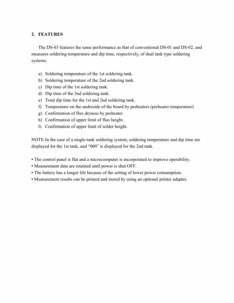
2. FEATURES The DS-03 features the same performance as that of conventional DS-01 and DS-02, and measures soldering temperature and dip time, respectively, of dual tank type soldering systems. a) Soldering temperature of the 1st soldering tank. b) Soldering temperature of the 2nd soldering tank. c) Dip time of the 1st soldering tank. d) Dip time of the 2nd soldering tank. e) Total dip time for the 1st and 2nd soldering tank. f) Temperature on the underside of the board by preheaters (preheater temperature) g) Confirmation of flux dryness by preheater. h) Confirmation of upper limit of flux height. I) Confirmation of upper limit of solder height. NOTE: In the case of a single-tank soldering system, soldering temperature and dip time are displayed for the 1st tank, and “000” is displayed for the 2nd tank. The control panel is flat and a microcomputer is incorporated to improve operability. Measurement data are retained until power is shut OFF. The battery has a longer life because of the setting of lower power consumption. Measurement results can be printed and stored by using an optional printer adapter.
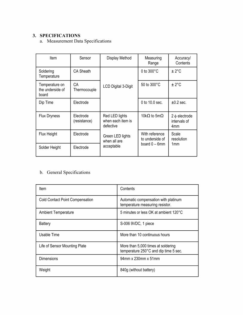
3. SPECIFICATIONS a. Measurement Data Specifications
Item Sensor Display Method Measuring Range
Accuracy/Contents
Soldering Temperature
CA Sheath LCD Digital 3-Digit
0 to 300°C ± 2°C
Temperature on the underside of board
CA Thermocouple
50 to 300°C ± 2°C
Dip Time Electrode 0 to 10.0 sec. ±0.2 sec.
Flux Dryness Electrode (resistance)
Red LED lights when each item is defective Green LED lights when all are acceptable
10kΩ to 5mΩ 2 φ electrode intervals of 4mm
Flux Height Electrode With reference to underside of board 0 – 6mm
Solder Height Electrode
Scale resolution 1mm
b. General Specifications
Item Contents
Cold Contact Point Compensation Automatic compensation with platinum temperature measuring resistor.
Ambient Temperature 5 minutes or less OK at ambient 120°C
Battery S-006 9VDC, 1 piece
Usable Time More than 10 continuous hours
Life of Sensor Mounting Plate More than 5,000 times at soldering temperature 250°C and dip time 5 sec.
Dimensions 94mm x 230mm x 51mm
Weight 840g (without battery)
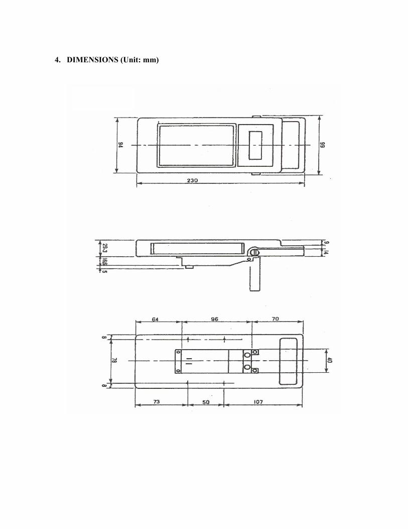
4. DIMENSIONS (Unit: mm)
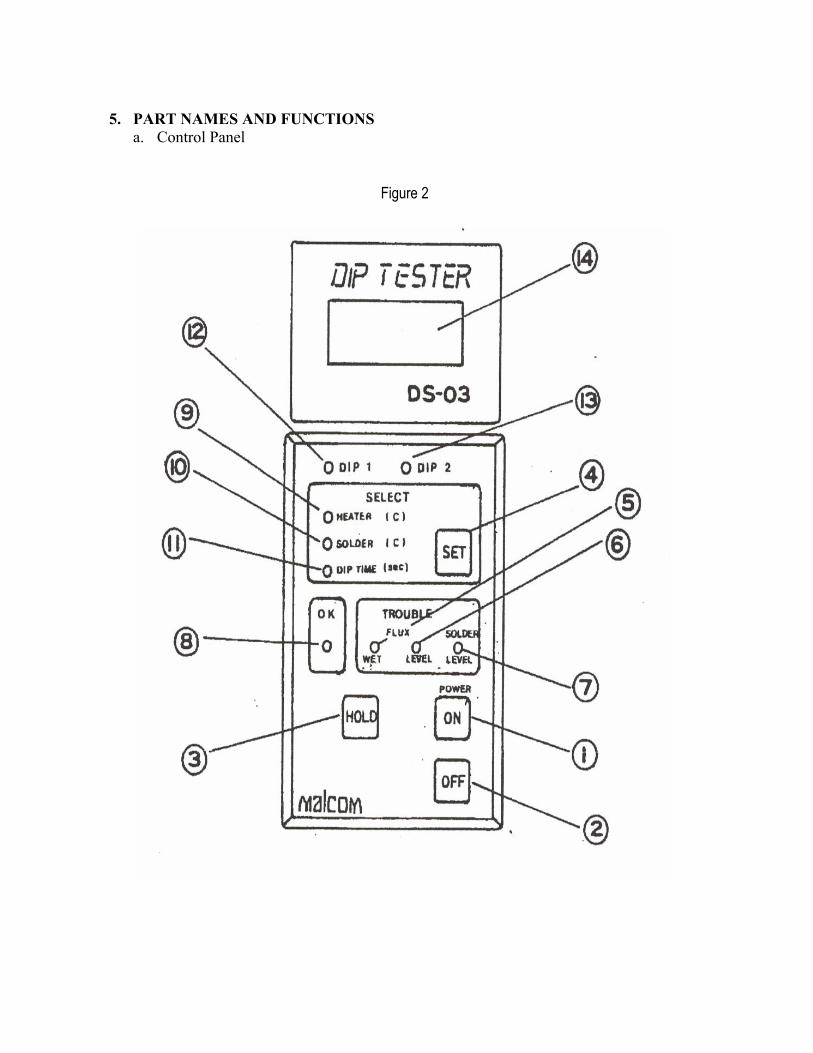
5. PART NAMES AND FUNCTIONS a. Control Panel
Figure 2
(1) POWER ON SWITCH Power is supplied when switch is pressed. Version statement appears for about 3 seconds, and then the system is ready to start. (2) POWER OFF SWITCH Power is shut OFF when switch is pressed. On turning OFF the system, the internal memory is reset to erase measurement results. (3) HOLD SWITCH This is not used in normal measurements. Your system will not measure temperature
of soldering tank and dip time unless the preheater temperature reaches 50°C. When the preheater temperature does not reach 50°C, you may press this switch and then feed the items to the line. With this, you can measure solder temperature and dip time even when the preheater temperature is low. This function is released when power is turned OFF.
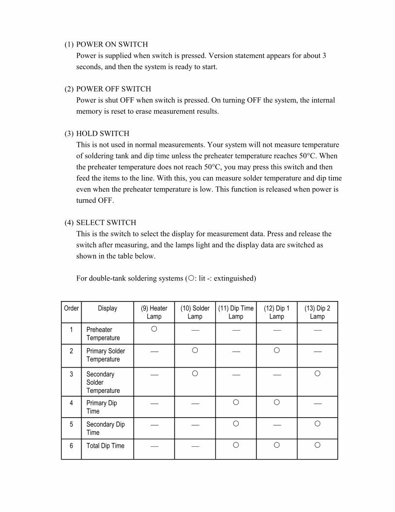
(4) SELECT SWITCH This is the switch to select the display for measurement data. Press and release the
switch after measuring, and the lamps light and the display data are switched as shown in the table below.
For double-tank soldering systems ( : lit -: extinguished)
Order Display (9) Heater Lamp
(10) Solder Lamp
(11) Dip Time Lamp
(12) Dip 1 Lamp
(13) Dip 2 Lamp
1 Preheater Temperature
2 Primary Solder Temperature
3 Secondary Solder Temperature
4 Primary Dip Time
5 Secondary Dip Time
6 Total Dip Time

(5) FLUX WET LAMP The flux coated on boards is dried by preheaters, and then enters the soldering tank.
If it is not fully dry, soldering can be unsatisfactory. Accordingly, dryness of the flux by preheaters is shocked with the flux dryness sensor (h) immediately before it enters the soldering tank. If the flux is not dry, the lamp lights up.
(6) FLUX LEVEL LAMP If the flux level is too high, the flux may spill to the board. The flux level sensor (g)
is used to set the upper limit for the flux level. If the flux is applied above the preset height, the flux level lamp lights up to indicate the flux leel is too high. The lamp is retained until power is shut OFF.
(7) SOLDER LEVEL LAMP Like the flux level, the upper limit for the soldering solution level is set by the
solder level sensor ©. The sensor monitors the level of the soldering solution. When the level becomes too high, the solder level lamp lights up. The lamp is retained until power is shut OFF.
(8) OK LAMP After measurement, OK lamp goes when flux dryness, flux level and solder level
were normal to indicate that there were no abnormal measurements. (9) HEATER LAMP The lighting heater lamp indicates that the figures on display are preheater
temperatures. Immediately after making power, heater lamp goes on and preheater temperatures are displayed.
(10) SOLDER LAMP The lighting solder lamp indicates that the figures on display are the first or second
solder temperature. The primary and secondary solder temperature are identified by (12) First Dip Lamp and (13) Second Dip Lamp. On making power, “000” will be displayed in place of temperature even if you try to display solder temperature with (4) Select Switch when no measurements have been made. For a single-solder tank, the lamp goes on as if the secondary solder temperature were displayed, but actually, the secondary solder temperature is displayed as “000”.
(11) DIP TIME LAMP The lighting dip time lamp indicates that the figures on display are dip time.
Primary dip time is displayed when (12) First Dip Lamp is lit; secondary dip time when (13) Second Dip Lamp is lit; and total dip time when both lamps are lit.
(12) FIRST DIP LAMP The lighting lamp indicates that the primary solder temperature or dip time is
shown. (13) SECOND DIP LAMP The lighting lamp indicates that the secondary solder temperature or dip time is
shown. (14) LCD DISPLAY The LCD display show various measurement, temperature and dip time. The LCD
display goes off and OVER mark is shown in the lower left hand corner of the LCD when the battery is low; battery voltage dropped; and it is time to replace the battery.

b. Sensors
Figure 3

(a) DIP TIME SENSOR This is the electrode to detect dip time in the solder tank. (b) FLUX WET SENSOR This is the sensor to detect dryness of flux located between these two electrodes as
electri resistance. (Resistance varies with the flux to use. See II-3.b for details). (c) PREHEATER TEMPERATURE SENSOR This is the CA thermocouple to detect the temperature on the underside of boards
heated by preheaters. (d) SOLDER TEMPERATURE SENSOR This is the CA sheath thermocouple to detect solder temperature. It is mad of soft
material. Do not have it caught, drop, change the shape, or bend.. (e) SOLDER LEVEL SENSOR This is the electrode to detect the highest solder level. (See II-1.b) for instructions. (f) SOLDER LEVEL INDICATOR This indicates the height to set the upper limit for the solder level. (g) SOLDER LEVEL SENSOR FIXING SCREW This screw is loosened when setting the upper limit for solder level. The sensor is
fixed when measuring. (h) FLUX LEVEL SENSOR This is the electrode to detect the highest flux level. (See II-1.b) for instructions. (i) FLUX LEVEL SENSOR FIXING SCREW This indicates the height to set the upper limit for the solder level. (j) FLUX LEVEL SENSOR FIXING SCREW This screw is loosened when setting the upper limit for solder level. It is tightened
to fix the sensor when measuring.
(k) F.S. DIAL If you see indicators (f) and (I) are at the lowest position on the scale, you can assume that the sensors for the flux and solder levels are in the same position as the underside of the printed circuit boards. The scale is graduated in 1mm intervals.
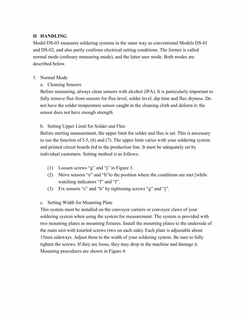
II HANDLING Model DS-03 measures soldering systems in the same way as conventional Models DS-01 and DS-02, and also partly confirms electrical setting conditions. The former is called normal mode (ordinary measuring mode), and the latter user mode. Both modes are described below. 1. Normal Mode a. Cleaning Sensors Before measuring, always clean sensors with alcohol (IPA). It is particularly important to
fully remove flux from sensors for flux level, solder level, dip time and flux dryness. Do not have the solder temperature sensor caught in the cleaning cloth and deform it: the sensor does not have enough strength.
b. Setting Upper Limit for Solder and Flux Before starting measurement, the upper limit for solder and flux is set. This is necessary
to use the function of I-5, (6) and (7). The upper limit varies with your soldering system and printed circuit boards fed to the production line. It must be adequately set by individual customers. Setting method is as follows:
(1) Loosen screws “g” and “j” in Figure 3. (2) Move sensors “e” and “h”to the position where the conditions are met [while
watching indicators “f” and “I”. (3) Fix sensors “e” and “h” by tightening screws “g” and “j”. c. Setting Width for Mounting Plate This system must be installed on the conveyor carriers or conveyor claws of your
soldering system when using the system for measurement. The system is provided with two mounting plates as mounting fixtures. Install the mounting plates to the underside of the main unit with knurled screws (two on each side). Each plate is adjustable about 15mm sideways. Adjust them to the width of your soldering system. Be sure to fully tighten the screws. If they are loose, they may drop in the machine and damage it. Mounting procedures are shown in Figure 4.

4) MEASUREMENT 1. Press POWER ON SWITCH to make power. On making power, LCD’s other than BATT go on, and “V0.3” (Version No.) appears. The display lasts about three seconds, and the system is ready to start. 2. Be sure HEATER lamp is lit, and a temperature closed to room temperature is shown. If a temperature much higher than room temperature (by 5°C or more) is shown, turn the system OFF, and cool it OFF (to approximately 25°C). Turn the system ON. NOTE: If you see OVER display, take necessary action by referring to III-1. 3. Be sure you have already adjusted the mounting width of the system in the steps shown in II-1.c. Install the unit on the carrier of the conveyor. For a unit without carriers, fix the system by hooking plates on the claws on the conveyor. Note that if the system is loose and moves, stable data measurement is not possible. 4. When the soldering operation ends, the system is lifted and the measurement ends. Be sure not to turn power OFF. If you turn power OFF on ending the operation, the data are erased. WARNING!!! BE CAREFUL OF GETTING BURNED BECAUSE THE SYSTEM IS HOT WHEN LIFTING IT!!
Figure 4
Mounting holes on the underside of dip
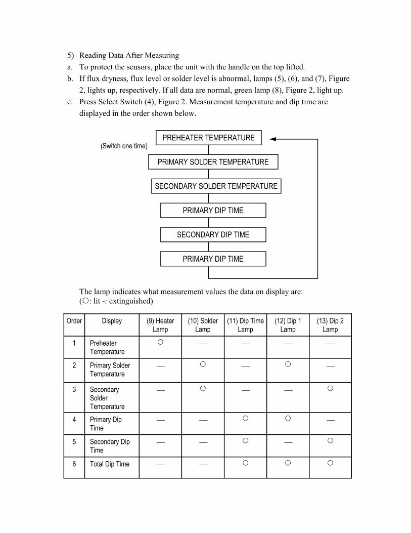
5) Reading Data After Measuring a. To protect the sensors, place the unit with the handle on the top lifted. b. If flux dryness, flux level or solder level is abnormal, lamps (5), (6), and (7), Figure 2, lights up, respectively. If all data are normal, green lamp (8), Figure 2, light up. c. Press Select Switch (4), Figure 2. Measurement temperature and dip time are displayed in the order shown below.
(Switch one time) PREHEATER TEMPERATURE
PRIMARY SOLDER TEMPERATURE
SECONDARY SOLDER TEMPERATURE
PRIMARY DIP TIME
SECONDARY DIP TIME
PRIMARY DIP TIME
The lamp indicates what measurement values the data on display are: ( : lit -: extinguished)
Order Display (9) Heater Lamp
(10) Solder Lamp
(11) Dip Time Lamp
(12) Dip 1 Lamp
(13) Dip 2 Lamp
1 Preheater Temperature
2 Primary Solder Temperature
3 Secondary Solder Temperature
4 Primary Dip Time
5 Secondary Dip Time
6 Total Dip Time
NOTE: When measuring in a single-tank soldering system, the secondary solder temperature and dip time are displayed as “000” or “00.0”. The total dip time is the same value as primary dip time.
4). To print the measurement results, set the system to the optional printer before shutting OFF power for the system after measurement. 5) After having recorded the results of measurement, press POWER OFF switch, turn power OFF, and cool down the system to room temperature. 2. Activating User Mode As mentioned before, the electrical setting of DS-03 main unit can be partly confirmed in the user mode, in addition to the functions of conventional dip testers. a) Turn power OFF. b) Press POWER On switch while pressing HOLD switch (3), Figure 2, to turn power ON. c) The display read “V0.3” does not appear, try again. d) The version statement goes off in about 5 seconds. HEATER lamps are lit, and preheater temperature are displayed. e) The display changes each time you press SELECT switch.

PREHEATER TEMPERATURE (HEATER lamp lights)
SOLDER TEMPERATURE (SOLDER lamp lights)
DS-03 INTERNAL TEMPERATURE (No lamp lights)
FLUX DRYNESS RESISTANCE (FLUX WET lamp lights)
NOTE: Preheater and solder temperature are not measurement values but the current temperatures of preheater and solder temperature sensors. Touch the solder temperature sensor with your finger, and you can confirm the temperature change.
NOTE: Flux dryness resistance is described briefly in II-3.b, you need only to confirm the
values at this stage.
3) What you should know This section describes the items which have not been mentioned in the previous sections. a. Function of DS-03 during measurement (in normal mode)
(1) On making power, the version statement appears for approximately 3 seconds. The system is then ready for measurement. Preheater temperature are displayed. (2) Install the system on your soldering system. On reaching the fluxer and coating flux, FLUX LEVEL lamp lights up when the flux attaches to FLUX LEVEL sensor which has been set. (3) The sensor board is heated by the preheater and the preheater temperature rises. If the preheater temperature is below 50°C, solder temperature will not be measured after plunging into the solder tank. (4) Having passed through the preheaters, the maximum temperature received from the preheaters is held and stored. (5) On plunging into the first solder tank, the dip sensor on the sensor board is electrically shorted, and detects that the subject has plunged into the first solder tank. FLUX WET lamp lights up when FLUX WET sensor detects a resistance value lower than the preset flux dryness resistance. (6) The solder temperature sensor starts measurement when the dip sensor (4) was electrically shorted. Note that no measurement will be made even when the dip sensor was shorted if the preheater sensor is still below 50°C at this time. Further, when you pressed HOLD button before measurement, the system starts measuring solder temperature as soon as the dip sensor is shorted even if the preheater temperature is below 50°C. (7) SOLDER LEVEL lamp goes on when the solder liquid level touches the SOLDER LEVEL sensor while passing through the solder tank. (8) Measurement of the solder temperature of the first solder tank is completed when the dip sensor is electrically released on leaving the first solder tank. (9) Like the first tank, plunge into the second solder tank is detected when electric short of the dip sensor is detected. (10) Measurement of the solder temperature of the second tank starts with the detection of the plunge of the second tank. Passage is confirmed on detecting electrical release of the dip sensor. Measurement of the solder temperature of the second tank is completed at this time.
(11) Dip time is a time period from when the dip sensor plunged into the solder tank and electrically shorted to when it is released. (12) OK lamp goes on immediately after passing the first solder tank when the preset conditions were met. When there is trouble in the second solder tank OK lamp goes off and TROUBLE lamp goes on instead.
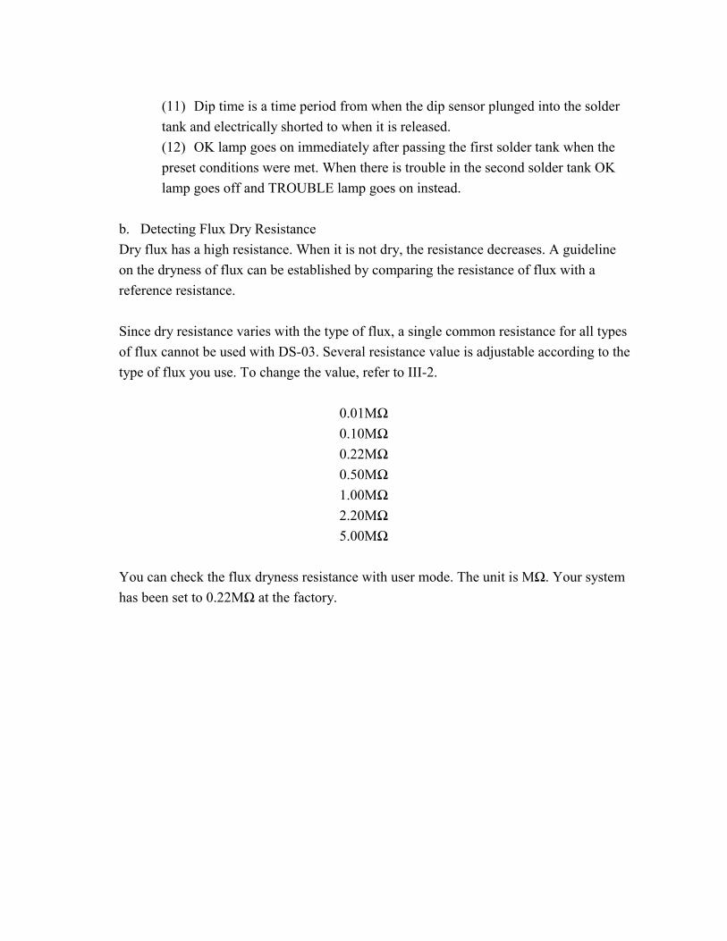
b. Detecting Flux Dry Resistance Dry flux has a high resistance. When it is not dry, the resistance decreases. A guideline on the dryness of flux can be established by comparing the resistance of flux with a reference resistance. Since dry resistance varies with the type of flux, a single common resistance for all types of flux cannot be used with DS-03. Several resistance value is adjustable according to the type of flux you use. To change the value, refer to III-2.
0.01MΩ 0.10MΩ 0.22MΩ 0.50MΩ 1.00MΩ 2.20MΩ 5.00MΩ
You can check the flux dryness resistance with user mode. The unit is MΩ. Your system has been set to 0.22MΩ at the factory.
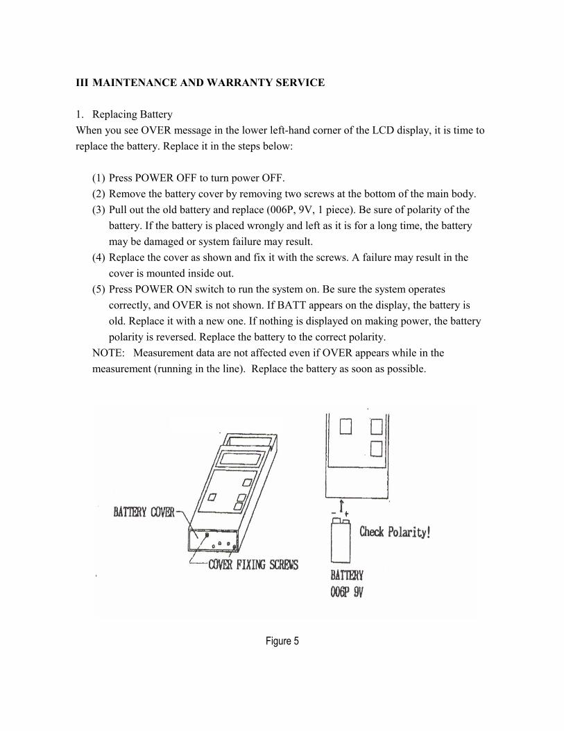
III MAINTENANCE AND WARRANTY SERVICE 1. Replacing Battery When you see OVER message in the lower left-hand corner of the LCD display, it is time to replace the battery. Replace it in the steps below: (1) Press POWER OFF to turn power OFF. (2) Remove the battery cover by removing two screws at the bottom of the main body.
(3) Pull out the old battery and replace (006P, 9V, 1 piece). Be sure of polarity of the battery. If the battery is placed wrongly and left as it is for a long time, the battery may be damaged or system failure may result. (4) Replace the cover as shown and fix it with the screws. A failure may result in the cover is mounted inside out. (5) Press POWER ON switch to run the system on. Be sure the system operates correctly, and OVER is not shown. If BATT appears on the display, the battery is old. Replace it with a new one. If nothing is displayed on making power, the battery polarity is reversed. Replace the battery to the correct polarity. NOTE: Measurement data are not affected even if OVER appears while in the measurement (running in the line). Replace the battery as soon as possible.
Figure 5
2. Changing Flux Dry Resistance Dry resistance of flux can be varied. The following resistance values are available for detection with the DS-03. The steps to change the values are as described below: 0.01MΩ 0.10MΩ 0.22MΩ 0.50MΩ 1.00MΩ 2.20MΩ 5.00MΩ NOTE: Your system has been set to 0.22MΩ at the factory. (1) Shut OFF power with POWER OFF switch. (2) Remove the battery cover referring to “II-1 Replacing the Battery”. (3) Pull out the battery. (4) Locate a small switch on the side of the battery case. Slide the switch knob away from
you. (5) Replace the battery and the cover. (6) Turn power ON. Current resistance is displayed. (7) The resistance value changes each time you press and release SELECT switch. (8) Continue to press and release SELECT switch until the desired value appears. With the
value on display, press HOLD switch. The value is stored. (9) Turn power OFF. Remove the cover and the battery. Reset the switch know to original
position. (10) Replace the battery and the cover. (11) Turn the power ON. Check that the system operates normally. If not, re-check polarity
of the battery and the position of the switch.

3. Checking Accuracy For correct measurement, the system must operate normally, and the performance must be maintained in good condition. Check accuracy of the system periodically, and calibrate if the performance shows difference. Accuracy is maintained for a long time if the system is checked for accuracy once every 6 months by the user, in addition to the yearly calibration. Steps for accuracy confirmation are described below. Preparation: - Calibration CA sensor (optional) - Standard glass thermometer - Boiling water - Water of ordinary temperature
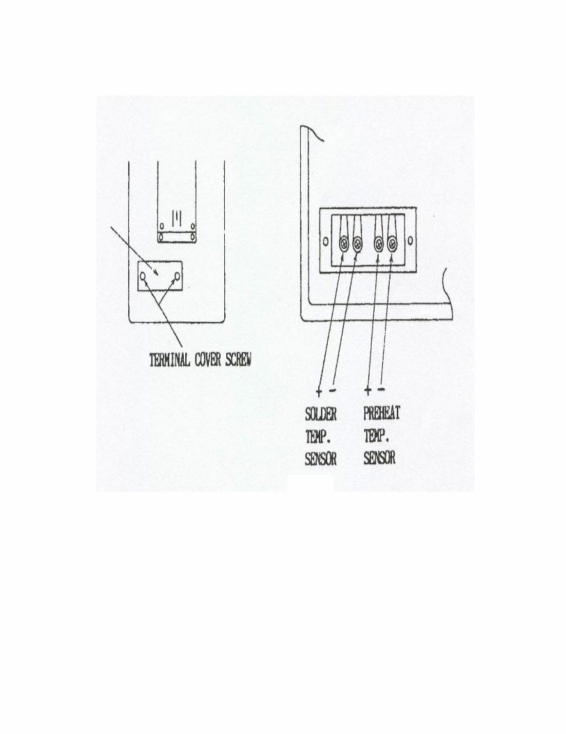
(1) Turn power OFF. (2) Remove the terminal cover on the sensor plane by removing two screws. (3) Remove the solder temperature sensor, and install the calibration CA sensor. (4) Put the calibration CA sensor and the standard glass thermometer in the boiling water. (5) Press POWER ON SWITCH while pressing HOLD switch to activate the user mode. Select solder temperature (See II-2.a). (6) Check that the difference between the temperature on the LCD and the reading of the glass thermometer is within ±2°C. (7) Put the calibration CA sensor and the standard glass thermometer in the water of ordinary temperature. Like (6) above, check that the difference between the temperature on the LCD and the reading of the glass thermometer is within ±2°C. (8) Turn power OFF. (9) Remove the calibration CA sensor from the main unit, and replace the solder temperature sensor.
4. Repair & Calibration Should you experience any difficulties in operating DS-03, and/or calibration is required, please contact your Malcom dealer or Malcom Instruments Corporation for assistance. IMPORTANT!! DO NOT ATTEMPT TO DISASSEMBLE OR SERVICE THE EQUIPMENT YOURSELF!!
MALCOMTECH INTERNATIONAL 26200 Industrial Blvd.
Hayward, CA 94545 U.S.A. Tel. (510) 293-0580 Fax. (510) 293-0940
Email. [email protected] Web. www.malcomtech.com
IV. WARRANTY Malcom Company Limited warrants this equipment against defects in parts and workmanship for one full year from date of purchase. The company will, at its own discretion, repair or replace any defective parts, which the company, upon inspection shall determine to be defective in material and/or workmanship. This is provided that the unit is returned, in safe proper packing, to the dealer or manufacturer. The following will void the warranty: - improper installation, abuse, misuse or misapplication, use beyond specifications, namely prolonged exposure to high temperatures, improper storage, damage caused from accidents, damages caused by improper packing. Malcom shall not be held responsible for damage caused from: natural and man-made disasters, pollution, improper operating environment, abnormal voltages or transient power surges.
SERVICE Thank you for purchasing this Malcom product. It was manufactured using the highest quality components and was meticulously adjusted and calibrated to factory specifications. We hope that it will provide you with many years of trouble-free operation. Should you encounter difficulty in using your instrument, or if it’s performance has become abnormal, please consult the troubleshooting section of your operation manual. Should this not enable you to solve the problem, do not attempt to dissemble, lubricate or repair the unit yourself, doing so will void the warranty. Instead, contact Malcom Instruments directly at:
Tel. (510) 293-0580 Fax. (510) 293-0940 Email. [email protected]
Quite often it is possible to resolve problems over the phone. If the difficulty is such that it requires the return of the product for repair, please secure the instrument with the supplied shipping brackets and place it into its original packing. If this is not possible, use a strong tape or cord to secure the unit for shipping. Pack the device in a rugged box much larger than the actual instrument. Use plenty of packing material that is elastic, such as bubble wrap. Styrofoam, etc. Do not use material such as newspaper, popcorn or wood shavings. Damages caused by shipping is not covered by the warranty. Send the unit, postage prepaid and insured, to the address given below.
Warranty The warranty for your Malcom product is six (6) months parts, and three (3) months labor. To guarantee in-warranty service, please fill out the below sheet and return to:
Malcomtech International, 26200 Industrial Blvd., Hayward, CA 94545 Your time in this matter is greatly appreciated.
Model: _____________________ Serial Number: _________________________
—————————–—————————————– cut on this line —————————————————– Model: _________________________ Serial: _________________ Purchase Date: ________________ Company: _____________________________________________________ Name of Owner/Operator: ______________________________________ Tel. ( )_______________________ Company Address: ______________________________________________________________________________ City/State/Zip: _________________________________________________________________________________
NOTE: NO WARRANTY WILL BE HONORED WITHOUT THIS FORM ON FILE AT MALCOM.
MALCOMTECH INTERNATIONAL 26200 Industrial Boulevard
Hayward, CA 94545 Tel. (510) 293-0580 Fax. (510) 293-0940
MANUFACTURERS SPIRAL VISCOSITY MEASUREMENT DE-
VICES SOLDERING PROCESS CONTROL DEVICES
Email. [email protected]