dir 1000587r002 version 02 140g-nti-e12; 140g-ntk...
TRANSCRIPT

DIR 1000587R002 Version 02 140G-NTI-E12; 140G-NTK-E12; 140G-RTI-E30; 140G-RTK-E30
Bul. 140G/140MG
LSIG and LSIG-MM trip unit for 140G-N/ 140G-NS/ 140G-R
WARNING:
WARNUNG:
AVERTISSEMENT:
To prevent electrical shock, disconnect from power source beforeinstalling or servicing. Install in suitable enclosure. Keep free from contaminants.
Per prevenire infortuni, togliere tensione prima dell'installazione omanutenzione. Installare in custodia idonea. Tenere lontano da contaminanti.
Vor Installations- oder Servicearbeiten Stromversorgung zurVermeidung von elektrischen Unfällen trennen. Die Geräte müssen in einempassenden Gehäuse eingebaut und gegen Verschmutzung geschützt werden.
Avant le montage et la mise en service, couper l'alimentationsecteur pour éviter toute décharge. Prévoir une mise en coffret ou armoire appropriée.Protéger le produit contre les environnements agressifs.
Desconéctese de la corriente eléctrica, antes de la instalación o
AVVERTENZA:
ADVERTENCIA:del servicio, a fin de impedir sacudidas eléctricas. Instálelo en una caja apropiada. Manténgalo libre de contaminantes.ATENÇÃO: Para evitar choques, desconectar da corrente elétrica antes de fazer a instalação ou a manutenção. Instalar em caixa apropriada. Manter livre de contaminantes.
Installation - Installazione - InstalaciónInstalação - -
(Follow NFPA70E requirements).
(1)DIR 1000587R0002 (Version 02)

Index
1. LSIG and LSIG-MM Trip Units Functional Comparison . 31.1. Compatibility between trip units and CB. . . . . . . . . 31.2. Abbreviations . . . . . . . . . . . . . . . . . . . . . . 31.3. Safety Notes. . . . . . . . . . . . . . . . . . . . . . . 31.3.1. Notes for dielectric tests . . . . . . . . . . . . . . . . . 3
2. LSIG Trip Unit . . . . . . . . . . . . . . . . . . . . . . 42.1. Overview . . . . . . . . . . . . . . . . . . . . . . . . 42.2. Main specifi cations . . . . . . . . . . . . . . . . . . . 42.2.1. Protections . . . . . . . . . . . . . . . . . . . . . . . 42.2.2. Functions . . . . . . . . . . . . . . . . . . . . . . . . 42.2.3. Accessories . . . . . . . . . . . . . . . . . . . . . . . 42.2.4. Compatibility CB. . . . . . . . . . . . . . . . . . . . . 52.2.5. Standards . . . . . . . . . . . . . . . . . . . . . . . . 52.2.6. Environmental characteristics . . . . . . . . . . . . . . 52.2.7. Electrical characteristics. . . . . . . . . . . . . . . . . 52.3. User interface . . . . . . . . . . . . . . . . . . . . . . 62.3.1. Dip switches . . . . . . . . . . . . . . . . . . . . . . . 62.3.2. LED . . . . . . . . . . . . . . . . . . . . . . . . . . . 72.3.3. iTest button . . . . . . . . . . . . . . . . . . . . . . . 72.3.4. Test connector . . . . . . . . . . . . . . . . . . . . . . 72.4. Protection functions . . . . . . . . . . . . . . . . . . . 72.4.1. Protection L . . . . . . . . . . . . . . . . . . . . . . . 82.4.2. Protection S . . . . . . . . . . . . . . . . . . . . . . . 82.4.3. Protection I . . . . . . . . . . . . . . . . . . . . . . . 82.4.4. Protection G . . . . . . . . . . . . . . . . . . . . . . . 82.4.5. Neutral Protection . . . . . . . . . . . . . . . . . . . . 92.4.6. Protection against instantaneous short-circuit “Iinst” . . 92.4.7. Summary table of protections . . . . . . . . . . . . . . 92.4.8. Trip curves . . . . . . . . . . . . . . . . . . . . . . . 102.4.8.1. Trip curves for functions L-S(t =k/I2)-I . . . . . . . . . 102.4.8.2. Trip curves for functions L-S(t=k)-I . . . . . . . . . . 102.4.8.3. Trip curves for function G . . . . . . . . . . . . . . . 112.5. Main functions . . . . . . . . . . . . . . . . . . . . . 112.5.1. Measurement . . . . . . . . . . . . . . . . . . . . . 112.5.2. Self-monitoring . . . . . . . . . . . . . . . . . . . . 112.6. Putting into service and recommendations . . . . . . 122.6.1. Installation . . . . . . . . . . . . . . . . . . . . . . . 122.6.2. Connections . . . . . . . . . . . . . . . . . . . . . . 122.6.3. CS and TC connection check . . . . . . . . . . . . . 122.6.4. Connection of current sensor for external neutral . . . 122.7. Default parameters . . . . . . . . . . . . . . . . . . 122.8. Troubleshooting . . . . . . . . . . . . . . . . . . . . 132.8.1. Troubleshooting . . . . . . . . . . . . . . . . . . . . 132.8.2. In the case of a fault . . . . . . . . . . . . . . . . . . 13
3. LSIG-MM Trip Unit . . . . . . . . . . . . . . . . . . . 143.1. Introduction . . . . . . . . . . . . . . . . . . . . . . 143.2. Overview . . . . . . . . . . . . . . . . . . . . . . . 143.3. Specifi cations . . . . . . . . . . . . . . . . . . . . . 143.3.1. Protections . . . . . . . . . . . . . . . . . . . . . . 143.3.2. Functions . . . . . . . . . . . . . . . . . . . . . . . 143.3.3. Inputs/Outputs . . . . . . . . . . . . . . . . . . . . . 153.3.4. Accessories . . . . . . . . . . . . . . . . . . . . . . 153.3.5. CB compatibility . . . . . . . . . . . . . . . . . . . . 153.3.6. Standards . . . . . . . . . . . . . . . . . . . . . . . 153.3.7. Environmental characteristics . . . . . . . . . . . . . 153.3.8. Electrical characteristics. . . . . . . . . . . . . . . . 153.4. User interface . . . . . . . . . . . . . . . . . . . . . 163.4.1. LEDs. . . . . . . . . . . . . . . . . . . . . . . . . . 163.4.2. Push-buttons . . . . . . . . . . . . . . . . . . . . . 173.4.3. Display. . . . . . . . . . . . . . . . . . . . . . . . . 173.4.3.1. Graphic ammeter . . . . . . . . . . . . . . . . . . . 183.4.3.2. CB and trip unit alarms . . . . . . . . . . . . . . . . 183.4.3.3. Operating icons . . . . . . . . . . . . . . . . . . . . 193.5. User menus . . . . . . . . . . . . . . . . . . . . . . 193.5.1. Information Pages . . . . . . . . . . . . . . . . . . . 193.5.2. Menu Area. . . . . . . . . . . . . . . . . . . . . . . 203.5.2.1. Menu browsing . . . . . . . . . . . . . . . . . . . . 203.6. Protection functions . . . . . . . . . . . . . . . . . . 213.6.1. Notes about Protection Operation . . . . . . . . . . . 213.6.2. Protection L . . . . . . . . . . . . . . . . . . . . . . 213.6.2.1. Thermal memory L . . . . . . . . . . . . . . . . . . 223.6.3. Protection S . . . . . . . . . . . . . . . . . . . . . . 223.6.3.1. Thermal memory S . . . . . . . . . . . . . . . . . . 22
3.6.3.2. Start-up threshold S . . . . . . . . . . . . . . . . . 223.6.4. Protection "I". . . . . . . . . . . . . . . . . . . . . . 223.6.5. Protection “G” . . . . . . . . . . . . . . . . . . . . . 233.6.5.1. Start-up threshold “G” . . . . . . . . . . . . . . . . . 233.6.6. Protection "U" . . . . . . . . . . . . . . . . . . . . . 233.6.7. Protection "T" . . . . . . . . . . . . . . . . . . . . . 233.6.8. Load control function . . . . . . . . . . . . . . . . . 243.6.9. Neutral Protection . . . . . . . . . . . . . . . . . . . 243.6.10. Protection MM . . . . . . . . . . . . . . . . . . . . 243.6.11. Protection against instantaneous short-circuit “Iinst” . 243.6.12. Summary table of protection functions . . . . . . . . 253.6.13. Trip curves . . . . . . . . . . . . . . . . . . . . . . . 263.6.13.1. Trip curves for functions L-S(t=k/I2)-I . . . . . . . . . 263.6.13.2. Trip curves for functions L-S(t=k)-I . . . . . . . . . . 263.6.13.3. Trip curves for function L in accordance with IEC 60255-
121 (type A) . . . . . . . . . . . . . . . . . . . . . . 273.6.13.4. Trip curves for function L in accordance with IEC 60255-
121 (type B) . . . . . . . . . . . . . . . . . . . . . . 273.6.13.5. Trip curves for function L in accordance with IEC 60255-
121 (type C) . . . . . . . . . . . . . . . . . . . . . . 283.6.13.6. Trip curves for function G . . . . . . . . . . . . . . . 283.6.13.7. Trip curves for function U . . . . . . . . . . . . . . . 293.7. Measuring functions . . . . . . . . . . . . . . . . . . 293.7.1. Runtime measurements: current, voltage, power . . . 293.7.2. Trip. . . . . . . . . . . . . . . . . . . . . . . . . . . 303.7.3. Events . . . . . . . . . . . . . . . . . . . . . . . . . 303.7.4. Measurements Log register . . . . . . . . . . . . . . 303.7.5. Peak factor. . . . . . . . . . . . . . . . . . . . . . . 303.7.6. Contact wear . . . . . . . . . . . . . . . . . . . . . 303.8. Main functions . . . . . . . . . . . . . . . . . . . . . 313.8.1. Watchdog . . . . . . . . . . . . . . . . . . . . . . . 313.8.2. Circuit-breaker state . . . . . . . . . . . . . . . . . . 313.8.3. Function MM. . . . . . . . . . . . . . . . . . . . . . 313.9. Settings Menu . . . . . . . . . . . . . . . . . . . . . 313.9.1. Circuit-breaker. . . . . . . . . . . . . . . . . . . . . 313.9.2. Network frequency . . . . . . . . . . . . . . . . . . 313.9.3. Measurement Interval . . . . . . . . . . . . . . . . . 313.9.4. System . . . . . . . . . . . . . . . . . . . . . . . . 323.9.4.1. Language . . . . . . . . . . . . . . . . . . . . . . . 323.9.4.2. Password . . . . . . . . . . . . . . . . . . . . . . . 323.9.5. Display contrast . . . . . . . . . . . . . . . . . . . . 323.10. Test Menu . . . . . . . . . . . . . . . . . . . . . . . 323.10.1. Autotest . . . . . . . . . . . . . . . . . . . . . . . . 323.10.2. Trip test . . . . . . . . . . . . . . . . . . . . . . . . 323.10.3. MM Test . . . . . . . . . . . . . . . . . . . . . . . . 323.11. Putting into service and recommendations . . . . . . 333.11.1. Installation . . . . . . . . . . . . . . . . . . . . . . . 333.11.2. Uninstalling . . . . . . . . . . . . . . . . . . . . . . 333.11.3. Connections . . . . . . . . . . . . . . . . . . . . . . 333.11.4. CS and TC connection test . . . . . . . . . . . . . . 333.11.5. Current sensor connection for external neutral . . . . 333.11.6. Default parameters . . . . . . . . . . . . . . . . . . 343.12. Troubleshooting . . . . . . . . . . . . . . . . . . . . 353.12.1. Troubleshooting . . . . . . . . . . . . . . . . . . . . 353.12.2. In the case of a fault . . . . . . . . . . . . . . . . . . 36
4. ACCESSORIES . . . . . . . . . . . . . . . . . . . . 364.1. External neutral . . . . . . . . . . . . . . . . . . . . 364.2. Rating Plug . . . . . . . . . . . . . . . . . . . . . . 364.3. Battery Unit (140G-ELBU). . . . . . . . . . . . . . . 36
(2)DIR 1000587R0002 (Version 02)
(3)DIR 1000587R0002 (Version 02)
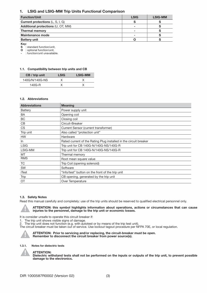
1. LSIG and LSIG-MM Trip Units Functional ComparisonFunction/Unit LSIG LSIG-MM
Current protections (L, S, I, G) S SAdditional protections (U, OT, MM) - SThermal memory - SMaintenance mode - SBattery unit O SKey:S : standard function/unit,O : optional function/unit,- : function/unit unavailable.
1.1. Compatibility between trip units and CB
CB / trip unit LSIG LSIG-MM
140G/N/140G-NS X X
140G-R X X
1.2. Abbreviations
Abbreviations Meaning
Battery Power supply unitBA Opening coilBC Closing coilCB Circuit-BreakerCS Current Sensor (current transformer)Trip unit Also called “protection unit” HWHW HardwareIn Rated current of the Rating Plug installed in the circuit breakerLSIG Trip unit for CB 140G-N/140G-NS/140G-RLSIG-MM Trip unit for CB 140G-N/140G-NS/140G-RMT Thermal memoryRMS Root mean square valueTC Trip Coil (opening solenoid)SW SoftwareiTest “Info/test” button on the front of the trip unitTrip CB opening, generated by the trip unitOT Over Temperature
1.3. Safety NotesRead this manual carefully and completely: use of the trip units should be reserved to qualifi ed electrical personnel only.
ATTENTION: this symbol highlights information about operations, actions or circumstances that can cause injuries to the personnel, damage to the trip unit or economic losses.
It is consider unsafe to operate this circuit breaker if:1. The trip unit shows visible signs of damage. 2. The trip unit does not function (e.g. with autotest or by means of the trip test unit).The circuit breaker must be taken out of service. Use lockout tagout procedure per NFPA 70E, or local regulation.
ATTENTION: Prior to servicing and/or replacing, the circuit-breaker must be open.Remember to disconnect the circuit breaker from power source(s).
1.3.1. Notes for dielectric tests
ATTENTION: Dielectric withstand tests shall not be performed on the inputs or outputs of the trip unit, to prevent possible damage to the electronics.

(4)DIR 1000587R0002 (Version 02)
2. LSIG Trip Unit
2.1. Overview
2.2. Main specifi cationsLSIG is an electronic device for AB 140G-N/140 G-NS/140G-R range of three-pole and four-pole Molded Case circuit breakers with functions for monitoring and for protecting against abnormal currents.
The trip unit installed on the circuit-breaker is connected to the current sensors for primary current reading, and to the Trip Coil for the circuit-breaker opening command.The sensors provide the primary current measurement and energy for powering the trip unit even in the absence of external power supply. Connected directly to an opening mechanism, the Trip Coil allows the CB to open. The control is transmitted to the Trip coil in accordance with the protection settings.
Dip switches on the front allow the main protections and settings to be adjusted, while the state of the trip unit is indicated by the leds of the front interface.
2.2.1. Protections
Symbol Protection againstL overload with inverse long time delayS overload with adjustable short time delayI instantaneous short-circuitG earth (ground) fault with adjustable delay
2.2.2. FunctionsLSIG includes various different functions:- Runtime measurement of the phase current and peak factor;- Autotest: continuous monitoring of the main connections to the trip unit, among which: current sensors, trip coil, rating plug, circuit-breaker state.
2.2.3. Accessories- External neutral, current sensor for protecting the external neutral pole (can only be confi gured for three-pole circuit-breakers).
More details are given from page page 36 of chapter 4, or in the dedicated manuals.
GISL
Service Connector - Battery Test (Input)
Battery Unit Catalog No:140G-ELBU [purchased separately]

(5)DIR 1000587R0002 (Version 02)
2.2.4. Compatibility CBLSIG can be installed in AB circuit-breakers of the three-pole, three-pole with external neutral or four-pole type from the 140G-R, 140G-N and 140G-NS (any size).
The CB model establishes the rated uninterrupted current the circuit-breaker is able to support (lu).
The adjustable protections (L, S, I and G) refer to the In size defi ned by the interchangeable Rating plug module installed on the actual trip unit.
2.2.5. StandardsLSIG has been designed to operate in accordance with the following international standards:- IEC 60947-2 Low voltage switchgear and control gear Part 2: Circuit-Breakers.- UL 489 Molded-Case Circuit-Breaker, Molded-Case Switches and Circuit-Breaker Enclosures- CSA C22.2 No. 5, Molded-Case Circuit-Breaker, Molded-Case Switches and Circuit-Breaker Enclosures
2.2.6. Environmental characteristics
Operating temperature -25 °C ... +70 °CStorage temperature -40 °C ... +70 °CRelative humidity 0% ... 98% with condensationDegree of protection (with LSIG installed in the circuit-breaker) IP 30
2.2.7. Electrical characteristicsThe trip unit is energized: - Directly by the internal current sensors connected to the busbars of each phase. In this case, the trip unit activates with the circuit-breaker closed and in the presence of a minimum three-phase current value. - By an external auxiliary power supply. In this case, continuous operation of the unit is guaranteed even with zero current on the busbars or with the circuit-breaker open.
Note:Rockwell Automation recommends use of a separate 24V DC power source to power the trip unit. This will eliminate the possibility of nuisance trips during startup/commissioning when reduced load currents may occur.
Primary current characteristics Range
Minimum three-phase busbar current >80AFrequency 50/60 Hz ±10%
Auxiliary power supply characteristics Range
DC voltage (galvanically separated) 24 Vdc ±20%Maximum ripple 5%Inrush current @ 24V ~2 A for 5msRated power @ 24V ~2 W
ATTENTION: Separate DC power source must be galvanically separated from ground, in accordance withUL 60950 (IEC 60950) or equivalent IEC 60364-41 [CEI 64-8].

(6)DIR 1000587R0002 (Version 02)
2.3. User interfaceLSIG allows the protections and main settings to be adjusted via the dip switches and has signalling LEDs for monitoring the state and alarms.
1 2 3 4 5 6
7 8
9
Ref. Description
1 Serial number of the trip unit
2 Test connector to connect battery unit
3 Section dedicated to protection L: threshold setting dip switches, time adjustment dip switches and alarm/trip LEDs
4 Section dedicated to protection S: threshold setting dip switches, time adjustment dip switches and alarm/trip LEDs
5 Section dedicated to protection I: threshold setting dip switches and trip LEDs
6 Section dedicated to protection G: threshold setting dip switches, time adjustment dip switches and alarm/trip LEDs
7 Dip Switches and indications for confi guration of rated frequency and neutral protection
8 Rating Plug
9 “iTest” button
2.3.1. Dip switchesThe dip switches on the front of LSIG are used for adjusting the tripping thresholds of each protection and the tripping time.The available combinations are given alongside each group of dip switches.The dip switches for regulating the tripping times of protections S (t2) and G (t4) can also be used for selecting the tripping curve:
Fixed time tripping curve. The following relation is used: t=k.
Inverse time tripping curve. The relation between the tripping time and over-current is given by the formula: t=k/I2
The dip switch settings can be changed when the trip unit is on and without alarms: updating is immediate and the unit need not be restarted.
ATTENTION: Settings changed by the user when the trip unit is in the alarm condition will not be activated until the alarm condition terminates.
An example of the dip-switch setting for the protection L function, with 2000A Rating Plug (In= 2000A) is given below.

(7)DIR 1000587R0002 (Version 02)
2.3.2. LEDThe following table shows LEDs signaling in accordance with the IEC standard 60073 (clause 4.2.3.2).
Type of information
Flashing slowly (0,5Hz) Flashing fast (2Hz)
LED fl ashing with two 0.5 sec
pulses every 2 sec
LED fl ashingwith one
pulse every 3 sec
LED on permanently
All LEDs
Single LED
All LEDs Single LED All
LEDsSingle LED Single LED All
LEDs Single LED
RE
D
OR
AN
GE
RE
D
RE
D
OR
AN
GE
RE
D
OR
AN
GE
OR
AN
GE
RE
D
RE
D
OR
AN
GE
TC error or TC disconnected
CS error or disconnected
Rating Plug/Installation error(1)
Protection timer error
Last trip (2)
Test button pressed and no failure detected (3)
L pre-alarm
Confi guration error(4)
Settings inconsistency
Normal operation of the trip unit (5)
CB Undefi ned or CB status error
(1) Rating plug disconnected or In > Iu.(2) The LED of the protection that has tripped or is being timed comes on to display the information. If it is the last trip, the LED
remains on for 2 sec or with fi xed light when there is external 24V power supply or battery: 140G-ELBU.(3) The information is displayed with all the leds on for as long as the test button remains depressed, or for 2 seconds if it is
pressed once.(4) Installed values differ from those stored by the trip unit: installation required (see par. 2.6.1).(5) In the absence of other information, “normal operation” is signalled 3s after the trip unit has been turned on.
ATTENTION: the LEDs only function if the trip unit has been powered. Once powered, the LEDs can be displayed for approximately 48 hours. To maintain trip status beyond 48 hours, use of separate 24V DC power source is recommended.
2.3.3. iTest buttonThe itest button can be used for different functions:- with the trip unit off, it allows to check the last recorded event (when pressed for about 1 second). The function is guaranteed for 48 hours after switch-off (absence of internal or external power supply). - with the trip unit energized by battery unit alone and with the CB open, it allows installation on the CB to be performed (see par. 2.6.1).- with the trip unit energized by battery unit and the CB closed, it allows performance of the LED test (when pressed for 3 seconds) and the trip coil operation test (when pressed for 7 seconds) with consequent opening of the CB.- It allows the Trip signal to be reset (when pressed for about 1 second) after a trip, with the trip unit on.
2.3.4. Test connectorThe front test connector allows battery unit 140G-ELBU to be connected for temporary powering of the trip unit.Consult the chapters dedicated to the accessory modules for further details.
2.4. Protection functionsLSIG handles up to 5 independent protection functions.The current signal from the current sensors is processed by the trip unit which, depending on the protection parameter settings, indicates alarms, performs delay processes and sends commands.
All the adjustable protections process according to the true root mean square value of the current values read by means of the current sensors.Each protection has an alarm led, which comes on in the case of delays (fl ashing) or trips (fi xed) and goes out when normal conditions restored
ATTENTION: when activated, the protections must respect the following rule:I1(protection L) < I2(protection S) and I2(protection S) < I3(protection I). When the trip unit is on, an incorrect protection threshold setting is signalled by the front leds (inconsistent settings).The trip unit has a “backup-protection” function. If the fi rst command transmitted to the trip coil fails to im-mediately open the circuit-breaker (partial TC failure), further trip commands are sent until it opens (absence of current and CB open).
NOTE: 2.4.1 through 2.4.6 explains each of the protection functions independently. Actual behavior of a circuit breaker depends on combination of settings for each protection function and is summarized in 2.4.7.

(8)DIR 1000587R0002 (Version 02)
2.4.1. Protection LProtection L is the only adjustable protection that cannot be disabled since it provides self-protection against circuit-breaker overloads. - The type of curve setting is t=k/I2 and the tripping time is calculated according to the value of If: - For fault currents If 12ln, the tripping time of the protection is given by the expression: t(s)= . If the calculated value is less than 1 second, the real tripping time is forced to 1 second (t(s)= 1s.) - For fault currents If > 12ln, the tripping time is always t(s)= 1s.
NOTES: - t(s)= estimated tripping time; - If= fault current; given in [In] (example: 0.7In) - I1 , t1= protection L parameters set by the user, given in [In] and [s]
Protection L has 3 operation conditions established by the primary current level If and by the setting of the protection itself I1:
If 0.9 xI1 No alarm, all settings possible. No time setting in progress.
0.9 xI1 < If < (1.05...1.2) xI1 Prealarm L signal, all settings possible. No opening time setting in progress.
(1.05...1.2) xI1 < If Alarm L signal, no setting possible. Opening time setting in progress.
ATTENTION: the protection L threshold range ensures that:- the trip unit is not in the alarm condition for current values below 1.05 xI1;- the trip unit is in the alarm condition for current values over 1.2 xI1.
2.4.2. Protection SThe protection, which can be disabled, can be the fi xed time (t=k) or inverse time (t=k/I2) type.
The tripping time with inverse time curve is given by the expression: t(s)= . If the calculated value is less than t2, the real tripping time is forced to t2 (t(s)= t2.)
NOTES: - t(s)= estimated tripping time; - If= fault current; given in [In] (example: 1.7In) - I2 , t2= protection S parameters set by the user, given in [In] and [s]
2.4.3. Protection IThis protection can be disabled; it is of the fi xed time (t=k) type, and is designed for a nil intentional delay.
2.4.4. Protection GThe protection, which can be disabled, can be the fi xed time (t=k) or inverse time (t=k/I2) type.
The tripping time with inverse time curve is given by the expression: t(s)= ; If the calculated value is less than t4, the real tripping time is forced to t4 (t(s)= t4).
NOTES: - t(s)= estimated tripping time; - If= fault current; given in [In] (example: 3.7In) - I4, t4= protection G parameters set by the user, given in [In] and [s]
LSIG is able to provide Ground (Earth) fault protection, by vectorally adding together the phase and neutral currents. The fault current is defi ned by the following formula:
If there is no fault in the circuit, IG = 0.Vice versa, the fault current will acquire an increasingly higher value, depending on the entity of the fault.
ATTENTION: protection G is disabled for current values exceeding 8In (for I40.8In), higher than 6In (for 0.5In I4<0.8In) and higher than 4In (for I4<0.5In)
ATTENTION: in the absence of a separate supplied 24V DC voltage, the minimum threshold accepted is 0.25In with rating plug= 400A and 0.2In for all the other sizes. If the entered value fails to comply with this limitation, the SW overrides the threshold until it reaches the minimum value accepted and the LEDs display the “Inconsistent
settings” error.

(9)DIR 1000587R0002 (Version 02)
2.4.5. Neutral ProtectionLSIG allows the current signal of the neutral pole to be processed with different ratios in relation to the phase values. The follow-ing values can be set for this protection: InN =Off - 50% - 100% - 200% * In. The neutral protection is set by default at a current value equal to 50% of the phase regulation.
Regulation of the neutral value (InN) must conform to the following formula: (I1 x InN) Iu.With four-pole circuit-breakers, the trip unit performs the test automatically and transmits a fault signal following failure to con-form to this formula. If the circuit-breaker is the three-pole type with external neutral, no tests will be performed by the trip unit and user needs to correct the settings.E.g. With CB 140G-R 2000 (Iu=2000A), Rating plug 1000A (In=1000A) and I1=1In, the InN setting can be: 50-100-200%. With CB 140G-R 2000 (Iu=2000A), Rating plug 2000A (In=2000A) and I1=1In, the InN can be: 50-100%.
The I1=1In setting is the maximum setting of the protection against overload. The real permissible maximum setting must take account of derating due to the temperature, terminals used and the altitude.
ATTENTION: In some installations, where particularly high harmonics occur, the current circulating on the neutral may be higher than that of the phases.
ATTENTION: For three-pole circuit-breakers without external neutral, the Neutral protection setting must be Off, otherwise the sensor presence error will be signalled (Error CS).In these cases, connect T5-T6 to the sliding contacts, as shown in the wiring diagrams.
ATTENTION: Failure to comply with the setting limits of “I1” and “InN” may result in damage to the circuit-breaker and consequent risks even for the operator.
ATTENTION: The protection setting is automatically 100% when the current value exceeds 15.5xIn on the neutral.
2.4.6. Protection against instantaneous short-circuit “Iinst”Iinst is a software override protection. The purpose of this protection is to maintain the integrity of the circuit-breaker and instal-lation in the case of particularly high current requiring shorter reaction times than those guaranteed by the instantaneous short-circuit protection.The protection cannot be disabled. It has a single fi xed time protection curve and a fi xed threshold level.
2.4.7. Summary table of protections
Pro
tect
ion
Dis
ablin
g
Trip threshold Trip time Trip thresholdtolerance (2)
Trip timetolerance (2)
L(t=k/I2) I1 =
0.4 - 0.425 - 0.45 - 0.475 - 0.5 - 0.525 - 0.55 - 0.575 - 0.6 - 0.625 - 0.65 - 0.675 - 0.7 - 0.725 - 0.75 - 0.775 - 0.8 - 0.825 - 0.85 - 0.875 - 0.9 - 0.925 - 0.975 - 1 x In
t1 = 3 - 12 - 24 - 36 - 48 - 72 - 108 - 144 s (1)
@If=3I1 Release between 1.05 and 1.2 x I1
± 10% If 6 x In± 20% If > 6 x In
S(t=k) I2 = 1 - 1.5 - 2 - 2.5 - 3 - 3.5 - 4 - 5 -
6 - 7 - 8 - 8.5 - 9 - 9.5 - 10 x In
Where If > I2± 7% If 6 x In± 10% If >6 x In
The best of the two data:± 10% or ± 40 mst2 = 0.1 - 0.2 - 0.3 - 0.4 -
0.5 - 0.6 - 0.7 - 0.8 s
S(t=k/I2) I2 = 1 - 1.5 - 2 - 2.5 - 3 - 3.5 - 4 - 5 -
6 - 7 - 8 - 8.5 - 9 - 9.5 - 10 x In
t2 = 0.1 - 0.2 - 0.3 - 0.4 - 0.5 - 0.6 - 0.7 - 0.8 s@ 10 In
± 7% If 6 x In± 10% If >6 x In
± 15% If 6 x In± 20% If > 6 x In
I(t=k) I3 = 1.5 - 2 - 3 - 4 - 5 - 6 - 7 - 8 - 9 -
10 - 11 - 12 - 13 - 14 - 15 x In 30 ms ± 10%
G(t=k) I4 =
0.2 - 0.3 - 0.4 - 0.6 - 0.8 - 0.9 - 1 x In
Where If > I4± 7%
The best of the two data:± 10% or ± 40 mst4 = 0.1 - 0.2 - 0.4 - 0.8 s
G(t=k/I2) I4 =
0.2 - 0.3 - 0.4 - 0.6 - 0.8 - 0.9 - 1 x In
Minimum trip time± 7% ± 15%
t4 = 0.1 - 0.2 - 0.4 - 0.8 s(1) The minimum value of this trip is 1s regardless of the type of curve
set (self-protection).(2) These tolerances apply in the following conditions:
- Self-energized trip unit in service conditions (no start-up) with 2 or 3 supplied phases and/or in presence of auxiliary supply.- operating temperature within the -25°...70° range.- primary current values within the operating limits (see par. 2.2.7)
For all cases not covered by the above table, the following tolerances apply:
Protection Trip threshold Trip timeL Release between 1.05 e 1.25 x I1 ± 20%S ± 10% ± 20%I ± 15% 60msG ± 10% ± 20%Others ± 20%
(10)DIR 1000587R0002 (Version 02)
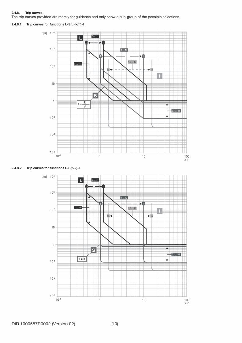
2.4.8. Trip curvesThe trip curves provided are merely for guidance and only show a sub-group of the possible selections.
2.4.8.1. Trip curves for functions L-S(t =k/I2)-I
t = kI2
2.4.8.2. Trip curves for functions L-S(t=k)-I
t = k

(11)DIR 1000587R0002 (Version 02)
2.4.8.3. Trip curves for function G
t = kI2
t = k
2.5. Main functions
2.5.1. Measurement
Type of measurement Range of values measured by the trip unit
Standard operation range
Range Tolerance %
Phase and neutral current 0.05 ... 16 In 0.3 ... 6 In ± 1.5Earth fault current 0.05 ... 4 In 0.3 ... 4 In ± 1.5
2.5.2. Self-monitoringLSIG provides certain self-testing functions to facilitate failure analysis in the case of faulty operation or incorrect confi guration of dip-switches and settings. Faults are signalled by a combination of led lights.The functions are as follows: Rating Plug validity. Checks to fi nd out whether the current sensors (CS) are connected correctly. Watchdog for proper connection of the Trip Coil (TC ).

(12)DIR 1000587R0002 (Version 02)
2.6. Putting into service and recommendations
2.6.1. InstallationCircuit-Breakers purchased with the trip unit assembled do not require this operation which is, however, necessary in the case of replacement.Comply with the following instructions if the trip unit on the CB is replaced:1. With the circuit-breaker open and possibly isolated, connect the tip unit to the circuit-breaker itself by connecting all the cables as indicated in the assembly documents.2. Power the unit with 24V DC power supply or battery unit 140G-ELBU.3. If there are no other errors apart from the confi guration one, press the “i Test” button for a few seconds until all the red leds fl ash to confi rm that installation has taken place.4. Remove the battery unit.5. Power the trip unit by means of any supply source (Vaux, battery unit).6. Make sure that there are no confi guration errors (check that the LEDs are on in the Alive LED ON confi guration).7. The circuit-breaker and trip unit can now be put into service.
2.6.2. ConnectionsATTENTION: Strict compliance with the wiring instructions given in this document is required.This will ensure compliance with all the international reference standards and guarantee that the trip unit func-tions perfectly even in heavy duty environmental and electromagnetic conditions. Pay particular attention to the earth connection.
2.6.3. CS and TC connection checkATTENTION: If the LSIG has been installed by the user, remember to check (with the CB open and Vaux or battery unit), prior to putting the circuit-breaker into service, to make sure that the CS and TC cables have been con-nected correctly. Make the correct connections if this is not the case. If all the red leds come on, it means that there is an error in the CS and/or TC connections
2.6.4. Connection of current sensor for external neutralATTENTION: Remember to set the InN in the appropriate way if the current sensor for the external neutral con-ductor must be connected to a three-pole circuit-breaker.During this phase, the circuit-breaker must be open and, if possible, isolated.
2.7. Default parametersPrior to commissioning, adjust protection parameters according to specifi c application.Rockwell Automation will apply the adhesive rating plates of all the variables concerning the CB (e.g. Type of CB, Rating Plug size, etc.) so as to provide the user with all the information needed to defi ne the parameters.
LSIG is supplied with the following default settings:
# Protection Threshold Time1 L 1 In 144 s2 S Off 0.1 s3 I 4 In --4 G Off 0.1 s5 Mains frequency 50 Hz (1)
6 Neutral sel (2)
NOTES: (1) = 50 Hz for IEC type CB 60 Hz for UL type CB(2) = Off for three-pole CB 50% for four-pole CB

(13)DIR 1000587R0002 (Version 02)
2.8. Troubleshooting2.8.1. TroubleshootingThe following table lists a series of typical service conditions, to help you understand and solve hypothetical faults or malfunctions.
NOTES: 1. Before consulting the following table, check for any optical signals provided by the LEDs.2. FN indicates the normal operation of the LSIG.3. If the following suggestions fail to solve the problem, please contact the AB assistance service.
N° Situation Possible causes Suggestions1 The trip test cannot be run 1. The busbar current is > 0
2. The TC is not connected3. Battery unit is not connected
1. Normal operation (FN)2. Check TC connection (see par. 2.6.3)3. Connect the battery unit
2 Trip times lower than expected
1. Threshold too low2. Curve too low3. Incorrect neutral selection
1. Correct threshold2. Correct curve3. Correct neutral adjustment
3 Trip times higher than expected
1. Threshold too high2. Curve too high3. Curve type "t=k/I2"
4. Incorrect neutral selection
1. Correct threshold2. Correct curve3. Select curve type "t=k"4. Correct neutral adjustment
4 Rapid trip, with I3=Off Iinst tripped FN short-circuit with high I5 Earth fault current beyond
thresholdG function automatically inhibited but no trip occurs
FN
6 Expected trip does not happen Function OFF FN enable protection function7 LEDs irregularly turned on see par. 2.3.28 Unexpected trip see par. 2.3.29 L LED (orange) fl ashing FN
2.8.2. In the case of a fault
ATTENTION: If the LSIG is suspected of being faulty, if there are signs of malfunctions or it has generated an unexpected trip, we advise you to strictly follow the recommendations below:
1. Press the “i Test” button (within 48 hours of CB opening or within 24 hours if the operating temperature is in the -40°..-25° range) and make a note of the led that comes on, the type of CB, the number of poles, any accessories connected, In, Serial Number. After 48 or 24 hours, depending on the case, the data is saved. Just the LED display is inhibited.
2. Prepare a brief description of the opening (what LEDs were displayed?, when did it happen?, how many times?, was it always under the same conditions? what type of load? what current? is the event reproducible?).
3. Send/communicate all the information collected, together with the circuit diagram for the circuit-breaker, to your Rockwell Automation Technical Support Team, for analysis.
ATTENTION: Letting a Circuit-Breaker run with a fault that has not been remedied may lead to an apparatus malfunction or shutdown. Removing the Circuit-Breaker from service immediately until it can be inspected and evaluated, will minimize the risk of damage to equipment or personel.

(14)DIR 1000587R0002 (Version 02)
3. LSIG-MM Trip Unit
3.1. IntroductionLSIG-MM possesses many common characteristics:- Graphic interface: display, push-buttons and interactive menu. - HW: connectors and accessory modules.- SW: basic protection and measuring functions.
3.2. Overview
External accessories
External Neutral Sensor
Temporary accessories (test connector)
Battery Unit
MMValues available GISL
3.3. Specifi cationsLSIG-MM, for 140G-N/140G-NS/140G-R circuit-breakers, is electronic device with functions for monitoring and for protecting against fault currents. The units also possess Measuring, Data Storage, Self-diagnosis, Load Control functionality.
The trip unit installed in the circuit-breaker is connected to the current sensors for primary current reading, to the Trip Coil for the circuit-breaker opening command and to the CB state contacts.The sensors provide the primary current measurement and energy for powering the trip unit even in the absence of external power supply.Connected directly to an opening mechanism, the Trip Coil allows the CB to open. The command is transmitted to the Trip coil in accordance with the protection settings.The state contacts of the CB provide information about the CB's position.
A graphic display and a set of push-buttons allow all the information about the trip unit to be accessed. They can also be used for adjusting the protections and settings and for reading the state and alarms. In addition, the presence of alarms is indicated by two front leds.
3.3.1. ProtectionsThe adjustable protections available are:
Symbol Protection againstL overload with inverse long time delayS overload with adjustable delayI instantaneous short-circuitG earth fault with adjustable delayU phase unbalanceOT temperature off rangeMM Instantaneous short-circuit (maintenance mode)
In addition, LSIG-MM provides fi xed protection against instantaneous short-circuits at high currents, known as Iinst.
3.3.2. FunctionsLSIG-MM includes various different functions: - Runtime measurement of the main electrical quantities available: phase current, peak factor; - Programmable measurements: periodic storage of maximum and minimum signals and waveforms; - Autotest: continuous monitoring of the main connections to the trip unit, among which: current sensors, trip coil, rating plug, circuit-breaker state.
- Maintenance information and counters: number of operations, estimated contact wear, events log.

(15)DIR 1000587R0002 (Version 02)
3.3.3. Inputs/OutputsLISG-MM is equipped with: - K14/K15, input contact for activating protection MM. - 95S/98S: output contact which supplies the state of protection MM.
Consult chapter 3.8.3 Function MM for further details.
3.3.4. AccessoriesA set of accessories adds optional functions to the basic version. - External neutral, current sensor for protecting the external neutral pole (can only be confi gured for three-pole circuit-breakers). - Battery unit allows the trip unit to be temporarily energized so as to view its state (via the LEDs) and perform installation.
More details are given from page page page 36 of chapter 4, or in the dedicated manuals.
3.3.5. CB compatibilityLSIG-MM can be installed on all three-pole, three-pole with external neutral or four-pole 140G-N, 140G-NS, 140G-R Frames.
The CB model establishes the rated uninterrupted current the circuit-breaker is able to support (lu).
The adjustable protections refer to size In, defi ned by the interchangeable Rating plug module, installed in the trip unit.
3.3.6. StandardsLSIG-MM has been designed to operate in accordance with the following international standards: - IEC 60947-2 Low voltage switchgear and control gear Part 2: Circuit-Breakers. - UL 489 Molded-Case Circuit-Breaker, Molded-Case Switches and Circuit-Breaker Enclosures. - CSA C22.2 No. 5, Molded-Case Circuit-Breaker, Molded-Case Switches and Circuit-Breaker Enclosures.
3.3.7. Environmental characteristics
Operating temperature (Standard version) -25°C ... +70°CStorage temperature -40°C ... +70°CRelative humidity 0% ... 98% with condensationDegree of protection (with trip unit installed in the CB). IP 30
3.3.8. Electrical characteristicsThe trip unit is energized: - Directly by the internal current sensors connected to the busbars of each phase. In this case, the trip unit activates with the circuit-breaker closed and in the presence of a minimum three-phase current value.
- By an external auxiliary power supply. In this case, continuous operation of the unit is guaranteed even with no current on the busbars or with the circuit-breaker open.
Primary current characteristics Range
Minimum three-phase busbar current (Low Power) > 80AMinimum three-phase busbar current (Full Power) > 160ARated operating frequency 50/60Hz ±10%
Auxiliary supply characteristics Activation of display lighting (3)
DC voltage (galvanically separated) 24 Vdc ±20%Maximum ripple 5%Inrush current @ 24Vdc ~2 A for 5msRated power @ 24Vdc ~3 W
ATTENTION: Separate DC power source must be galvanically separated from ground, in accordance withUL 60950 (IEC 60950) or equivalent IEC 60364-41 [CEI 64-8].
If supplied by primary current or voltage, LSIG-MM includes 3 different operating modes, depending on the level of the supply signals:- Low Power: this mode guarantees operation of all the protections provided by the tip unit, operation of the front LEDs and display energizing in the Low Power mode, but access to the menus is not allowed.- Full Power: this mode guarantees operation of all the protections provided by the trip unit, operation of the front LEDs and display energizing in the Full Power mode. Access to the menus is also allowed.- Full Power and display lighting: this mode includes all the Full Power functions and powers the display lighting system.

(16)DIR 1000587R0002 (Version 02)
3.4. User interfaceA graphic display and a push-button panel provide all the available settings and information.
1 2 3 4 5
6 7
Ref. Description1 Serial number of the trip unit2 State LED 3 Test connector4 Graphic display5 Main push-button panel6 Rating plug7 “i Test” button
3.4.1. LEDsThe 2 front LEDs provide information about the state of the trip unit and CB. Both leds function when the unit is on.
Signal Colour State Description
ALARM Red
OFF No protection or delay alarm
ON (Flashing @1Hz)
Delay in progress for one or more of the following protections: current (L, S, G), phase unbalance (U)
Alarm for one or more: Contact wear, Temperature
Connection error of one or more: Rating Plug, Trip Coil , Key plug error, Current sensorsInstallation error
ON (Fixed) Internal error
WARNING Yellow
OFF No CB error or alarm
ON (Flashing @0.5Hz) OT protection in prealarm
ON (Flashing @1Hz) OT protection in alarm state
ON (Fixed)
Protection L prealarmProtection U alarm with trip disabledDistorted wave form with > 2.1 Form factorContact wear within range: 80%<CW<100%Iw WARNING threshold exceededCB state errorConfi guration errorIncongruent settings

(17)DIR 1000587R0002 (Version 02)
3.4.2. Push-buttonsA push-button panel with 4 buttons is used to access the menus on the display of the trip unit. There is also an independent button at the side of the display, with various functions (iTest).
Key Name Description
ESC - Press ESC from the default page to access the main menu - Press ESC from within the menus to return to the previous level
ENTER - Press ENTER from within the menus to access the selected level or parameter - Press ENTER to confi rm the option selected
UP - Press UP or DOWN from the default page to access the pages with the available measurements (cur-rent values)
- Press UP or DOWN within the menus to scroll the menu options - Press UP or DOWN within the parameter or setting areas to change their valuesDOWN
iTest
- Press iTest from the default page to access the area with the information pages concerning the trip unit, the circuit-breaker and the last trip recorded.
- Press iTest after the CB has tripped because of an overcurrent event, to reset the TRIP state of the trip unit (the display is redirected to the default page and the SW register corresponding to Trip is reset)
- Press iTest when the trip unit is off to obtain a description of the last event that led to the trip unit being shut off (function available within 48h from shut-off).
ATTENTION: When parameters whose adjustment includes a large number of options or values are edited, the UP or DOWN buttons can be pressed and held down so as to scroll through the options faster and speed up the editing operations.
3.4.3. DisplayLSIG-MM are equipped with a 128x64 pixel graphic LCD display where the operator can view measurements and signals, and access the menus with all the settings.The degree of contrast of the menu display can be adjusted by selecting the Settings menu and Display Contrast parameter.
The display has 2 operating modes (the conditions are described in par. 3.3.8):- Low Power: the display is fi xed and appears as shown in the fi gure below:
Low Power
1
2
3
45
- Full Power: various menus and information areas can be accessed with the buttons in this confi guration: the main page is dis-played (default page) during normal operation, and appears as shown in the fi gure below:
6
2
3
7
5
The measurements area or the menu area are accessed from the default page. All the options within the menu are displayed as shown in the fi gure below:
2
Settings
Measurements
Protections
Protections settings
8
9
10
11
5
Access to the menus and the push-button panel is active in the Full Power mode. Consult the dedicated chapter for details about how to browse the menus (See par. 3.5).

(18)DIR 1000587R0002 (Version 02)
Ref. Description1 Phase current measurement2 CB and/or trip unit alarms (sinewave logo appears in the absence of alarms)3 Internal clock4 “Low Power“ message5 Operating icons6 Graphic ammeter and voltmeter7 Rms value and highest measured current phase (cyclically updated value)8 Name of the menu being browsed9 List of options available in the menu being browsed (the value that appears in black is the one that has been selected)10 Number of options available in the menu being browsed11 Value or description of the selected option
3.4.3.1. Graphic ammeterGraphic ammeter option is available in the default page.
The levels of the available measurements are displayed by a vertical bar.The current (phase) values are positioned along the abscissae, with the reference and rated value setting along the ordinate: an intermediate line indicates the 1In value for the current values.
1In
Example: if the bar corresponding to current I1 exceeds the intermediate line, it means that the measured value is higher than 1In.
3.4.3.2. CB and trip unit alarmsInformation about the state of the trip unit and CB is always available at the bottom left of the display (See par. 3.4.3 Display Ref.2). The sinewave logo appears in the absence of alarms. If one or more alarms have occurred, they will be displayed by a message that fl ashes every 2 seconds. The alarms are displayed in conjunction with an icon showing the type of alarm in question (information, active delay, danger).
Icon Message Description
Confi guration Inconsistent parameters or inconsistent data between key plug and trip unitPrealarm [L] / [T] Prealarm condition of the specifi ed protection. Example: “Prealarm L”Warning Iw Iw threshold exceededContact wear Contact wear prealarm (>80%)Date not valid Incorrect date that must be programmed (new trip unit that has been off for
over 48h)CB not defi ned “Open/closed” circuit-breaker state inconsistent or incorrectAlarm T Internal temperature of trip unit off-range (<-25° or >85°)Time delay [L] / [S] / [G] / [U] Time delay condition of the specifi ed protection, which can conclude with
an opening command transmitted to the CB.Contact wear Alarm for contact wear (=100%)Harmonic distortion Alarm for measured harmonic distortion (form factor>2.1)[G] / [T] (TRIP OFF) Alarm of the specifi ed protection, of which the trip function has been disabled. Alarm [U] Alarm of the specifi ed protection, of which the trip function has been disabled
or if the trip is activated but the CB is already openLoad [LC1] / LC2] Load control alarm. Example: “Load LC2“Sensor [L1] / [L2] / [L3] / [Ne] Alarm of the specifi c current sensor (disconnected or faulty). Example:
“sensor L3“TC disconnected Trip Coil disconnected or faultyRating Plug Rating plug absent, disconnected, faulty or of a model superior to the luInstallation Error following an incorrect installation procedure or failure to installPower factor Power factor module lower than set limit

(19)DIR 1000587R0002 (Version 02)
The following table describes all the messages that could appear on the display in a pop-up window after an unallowed attempt to confi gure parameters or settings.
Alarm message Description
Password error
Session impossible A programming session cannot be started due to a contingency (e.g. a timer-controlled delay still elapsing)
Value off range Value beyond the established limits
Failed 1001/2001 Inconsistency between thresholds of protections L and S
Failed 1002/2002 Inconsistency between thresholds of protections I and S
Failed 3001 Problems with language change
Failed 3003 Problems with neutral setting
Exception 6 Control momentarily unavailable
Unavailable Function temporarily unavailable
Invalid date Date and time not updated. Set them.
Parameters revised Programming session concluded correctly
Cancelled Programming session cancelled
Failed Programming session rejected
3.4.3.3. Operating iconsAn area with icons showing the operating conditions of the trip unit is available on the display. The area is at the bottom right of the display (See par. 3.4.3 Display Ref.5) and includes 2 positions in which the icons can be shown.
Starting from the position on the far right, a description of the available icons is given below:
Position Icon Condition Description
1OFF Separate 24V DC source is not present
ON Separate 24V DC source is present
2
OFF Editing of parameters and settings via the local mode. No update in progress
ON
Editing of parameters and settings via the local mode. Update in progress: the icon appears if the users has changed some of the parameters but has not yet completed the operation by selecting CONFIRM. The icon only disappears after the changes ave been confi rmed or annulled
3.5. User menusLSIG-MM come on in the Full Power mode in the presence of the supply conditions described in sect. 3.3.8 or if supplied by one of the following: Separate power supply or Battery unit.The operator can browse the menus on the display in the Full Power mode. When powered, the unit displays a default page from whence the operator can access three different areas:- Measurements Area, by using the UP and DOWN buttons.- Information Pages, by using the iTest button.- Menus Area, by using the ESC button to access and quit the menu section.
3.5.1. Information PagesThis area contains 3 pages of information about the trip unit and CB: “Protection unit“ page, “Circuit-breaker“ page and “Last opening“ page. Press the iTest button within 5 sec to change page.

(20)DIR 1000587R0002 (Version 02)
3.5.2. Menu AreaThe menu area features a tree structure allowing all the information and parameters to be managed with various levels of detail.The main menu, which the user can access by pressing ESC from the default page, includes 5 options:
Main Menu Option Description Paragraph
1. Protections Reading and adjustment of all the protections available 3.62. Measurements Reading of all the measurements made by the trip unit, Trip and events 3.73. Settings Reading and adjustment of the main settings of the trip unit, CB and modules 3.94. Test Allows diagnosis and state control tests to be performed 3.105. Information Reading of the main details about the trip unit and CB --
The various different menus are described in the sections indicated in the table.
3.5.2.1. Menu browsingThe operator can browse within each level by using the main push-button panel:- ENTER to access a submenu or confi rm an edited parameter- ESC to quit a submenu or annul the changes made to a parameter- UP and DOWN to scroll the menu options
The editing menus can only be accessed after the user password has been entered.
The parameters can be edited by scrolling the options available in the specifi c menu and by selecting the required option with the ENTER button. Some of the parameters update immediately (such as the date) while others require confi rmation (CONFIRM).To accomplish the CONFIRM operation, the operator must quit the menus through to level 1 where there is a new page called PROGRAMMING in which 3 options can be chosen: - CONFIRM: confi rms the changes made- ANNUL: annuls the changes made- EDIT: allows the operator to browse the menus again and make further changes to the parameters.Selection of the fi rst two options accesses a temporary window giving the programming result (parameters updated or operation annulled).
1/3
Confirm
Abort
Modify
Confirm
Programming

(21)DIR 1000587R0002 (Version 02)
3.6. Protection functionsLSIG-MM handle numerous independent protection functions.The current and internal temperature signals are processed by the trip unit which, depending on the protection parameter settings, indicates alarms, performs delay processes and sends commands.
The various types of adjustable protections are managed by the trip unit in different ways: - The current protections are processed according to the true root mean square value of the current values read by the current sensors.
- The temperature protection is monitored by means of the internal sensor of the trip unit.
The Iinst fi xed protection is also available and can neither be disabled nor adjusted.
The Protections menu also allows the operator to view and edit all the available parameters.
Protections Options available Trip unit
LSIG-MM
Protection L Threshold, Time, Curve, Thermal memory SProtection S Enabling, Threshold, Time, Curve, Thermal Memory, Startup SProtection I Enabling, Threshold, Startup SProtection G Enabling, Threshold, Time, Curve, Trip enabling, Startup SProtection U Enabling, Threshold, Time, Curve, Trip enabling SProtection T Enabling SLoad protection Enabling and threshold (1), Enabling and threshold (2), Enabling and threshold (Iw) SNeutral Protection Enabling, Threshold S(1)
Protection MM Enabling, Threshold S
Key:S : standard protectionO : optional function
Notes:1. : function available with four-pole CB, or three-pole CB in the 3P+N confi guration
NOTE: 3.6.2 through 3.6.11 explains each of the protection functions independently. Actual behavior of a circuit breaker depends on combination of settings for each protection function and is summarized in 3.6.12.
3.6.1. Notes about Protection OperationLSIG-MM is equipped with “backup-protection”. If the fi rst command to the trip coil fails to open the circuit-breaker immediately (TC locked), further trip commands are transmitted until the circuit-breaker opens.The declared tolerance values of the measurements and protections of the trip unit could change if the electrical characteristics of the current signals fail to comply with the limits specifi ed in chapter 3.3.8.
3.6.2. Protection LProtection L is the only protection that cannot be disabled since it provides self-protection against circuit-breaker overloads. The types of trip curves settable are divided into two groups according to the standard they refer to.
Standard trip curve according to IEC 60947-2Only one type of curve is settable (t=k/I2) as defi ned by the IEC standard 60947-2.The tripping time is calculated in relation to the value of If: - For fault currents If 12ln, the tripping time of the protection is given by the expression: t(s)= . If the calculated value is less than 1 second, the real tripping time is forced to 1 second (t(s)= 1s.).
- For fault currents If >12ln, the tripping time is always t(s)= 1s.
Standard trip curve according to IEC 60255-1213 types of curve settings can be made and are defi ned by standard IEC60255-121 as A, B and C.The protection trip time, with inverse time, is given by the expression:
b
Ikt
1 where
1II
I f
NOTES: - t(s): estimated tripping time - If : fault current; given in [In] (example: 0.7In) - I1 , t1: protection L parameters set by the user, given in [In] and [s]- , k: parameters suggested by standard IEC60255-121, which vary with the type of gradient selected (e.g. for type B
gradients: = 1 and k = 13.5) - b: parameter included to increase the number of curves with the same slope. This parameter is automatically calcu-
lated by setting parameter t1 (required tripping time with If= 3xI1).
Protection L has 3 operating conditions established by the fault current level If and by the setting of the protection itself I1:

(22)DIR 1000587R0002 (Version 02)
If 0.9 xI1 No alarm, all settings possible. No time delay in progress.
0.9 xI1 < If < (1.05...1.2) xI1 Prealarm L signal, all settings possible. No opening time delay in progress.
(1.05...1.2) xI1 If Alarm L signal, no setting possible. Opening time delay in progress.
ATTENTION: the protection L threshold entry range ensures that: - the trip unit does not set to the alarm status for current values less than 1.05 xI1; - the trip unit will set to the alarm status for current values exceeding 1.2 xI1.
3.6.2.1. Thermal memory LThe thermal memory function can be enabled for cable protection. It is based on the “L” parameter, defi ned as the tripping time of the curve (t1) selected at 1.25xI1.The tripping time of the trip unit will certainly be 100% of the selected value after time L has elapsed since the last overload or the last trip, otherwise the tripping time will be reduced in relation to the overload that has occurred or the time that has elapsed.
LSIG-MM trip unit has two instruments for processing the thermal memory. The fi rst only operates when the trip unit is energized (it also records overloads that have not lasted long enough to trip the CB), while the second operates even when the trip unit is not energized, reducing any trip times in the case of immediate reclosing and activating the moment the circuit-breaker trips.It is the trip unit that decides which of the two to use, depending on the situation in question.
ATTENTION: The thermal memory function can only be activated if the standard type of curve has been selected (t=k/I2)..
3.6.3. Protection SThis protection can be disabled; it can be of the fi xed time (t=k) or inverse time (t=k/I2); in the latter case, the trip time is given by the expression.The tripping time with inverse time curve is given by the expression: t(s)= . If the calculated value is less than t2, the real tripping time is forced to t2 (t(s)= t2.)
DEFINITIONS:t(s): estimated tripping time If : fault current; given in [In] (example: 1.4In) I2 , t2: protection S parameters set by the user, given in [In] and [s]
3.6.3.1. Thermal memory SThe thermal memory function can be enabled for cable protection in the case where the curve with inverse time is selected. This is based on the “tS” parameter defi ned as the trip time of the curve (t2) selected at 1.5xI2. The other characteristics are the same as those for thermal memory L.
3.6.3.2. Start-up threshold SThe start-up function can be selected in the case where the curve with fi xed time is selected.
The start-up function enables the protection threshold (S, I and G) to be changed during a time interval lasting “ts”, starting from “start-up”. The latter must be intended as follows: - Passage of at least one of the phase currents above the activation threshold of the adjustable Start-Up (0.1…10In, by 0.1In steps); A new start-up is possible after the current has dropped below this threshold.
3.6.4. Protection "I"The protection is enabled/disabled from the menu.
I
t
Start-Up Threshold I2
ts
Threshold I2
Activation of Start-Up
Threshold Start-Up activation
(23)DIR 1000587R0002 (Version 02)
3.6.5. Protection “G”Protection G is provided by the trip unit via vectorial calculation of the neutral and phase currents. The fault current is defi ned by the following formula:
In the case when the circuit does not show any fault, the module of the sum of these currents is always nil; vice versa the value of the fault current will take on an increasingly large value depending on the size of the fault. This operating mode is enabled by default.The protection, which can be disabled, can be the fi xed time (t=k), or inverse time (t=k/I2)
The tripping time with inverse time curve is given by the expression: t(s)= . If the calculated value is less than t4, the real tripping time is forced to t4 (t(s)= t4).
NOTES: - t(s): estimated tripping time - If : fault current; given in [In] (example: 0.4In) - I4 , t4: protection G parameters set by the user, given in [In] and [s]
ATTENTION: Protection G is disabled for current values of over 8In (for I4 0.8In), over 6In (for 0.5In I4<0.8In), over 4In (for 0.2In I4<0.5In) and over 2In (for I4<0.2In).
ATTENTION: In the absence of a separate supplied 24V DC voltage, the minimum threshold setting is 0.25In with rating plug= 400A and 0.2In for all the other sizes. If the entered value fails to comply with this limitation, the SW overrides the threshold until it reaches the minimum value accepted and “Confi guration” error appears on the display.
ATTENTION: It is possible to disable the trip control of the protection (“Enable Trip: Off”).In that case, for the whole duration of the unbalance the CB will not be opened, but only the condition will be signaled by means of the “warning” LED lit up and a warning message.
3.6.5.1. Start-up threshold “G”The function behaves in exactly the same way as the protection “S”.
3.6.6. Protection "U"Protection against current unbalance with a fi xed time response (can be disabled).The breaker trips when, for the t6 time setting or longer, an unbalance is detected between two or more phases that is higher than the I6 threshold setting.The percentage of current unbalance is calculated in the following way:
% Unbal = 100max
minmax .−III
where Imax is the maximum and Imin the minimum phase current.
The trip command of the protection can be disabled: in this case, CB opening is not controlled and the condition is merely sig-nalled by leds and a message on the display.
ATTENTION: When the value of the phase current is above 6xIn, the function “U” excludes itself because, in this case, the other protections intervene because the fault is considered as a phase fault.The protection is not enabled for maximum phase current values lower than 0.3xIn.
3.6.7. Protection "T"A sensor inside the trip unit signals abnormal temperature conditions which could lead to temporary or continuous faults in the electronic components of the unit.This protection has two states of operation:
State of “WARNING TEMPERATURE” with –25°C < temp. < -20°C or 70°C < temp. < 85°C :
the display is turned off and the “WARNING” LED fl ashes at 0.5Hz
State of “ALARM TEMPERATURE” with temp. –25°C or temp. 85°C : the display is turned off, the “WARNING”
and “ALARM” Leds fl ash at 2Hz and the Trip is activated (if enabled by means of the “Over Temper. Trip = On” parameter).
In the event of Warning and Alarm, the display is turned off, to preserve its functionality;The monitored temperature is not visible on the display.The protection is always active, both with auxiliary supply and in self-supply.
ATTENTION: If the Trip command of the protection were to be disabled, the trip unit would operate, with the circuit-breaker closed, within a temperature range where correct operation of the protections is not guaranteed.
(24)DIR 1000587R0002 (Version 02)
3.6.8. Load control functionSingle loads can be enabled/disabled on the load side before the overload protection L intervenes and trips the circuit-breaker on the supply side. This is performed by means of contactors or switch-disconnectors controlled by the trip unit via contact S51/P1.
The current thresholds are lower than those available with the protection L, so that the load control can be used to prevent trip-ping due to overloads. The function is active when an auxiliary power supply is present.The operating logic involves the activation of three contacts when the preset thresholds LC1, LC2 and Iw are exceeded.Thresholds LC1 and LC2 are expressed as a percentage of I1 (current threshold specifi ed for protection L) while the “warning current” Iw is expressed as an absolute value. The allowable values are given in the following table:
Threshold LC1 50%...100% x I1 step 1% I1Threshold LC2 50%...100% x I1 step 1% I1 Threshold Iw 0.3 ...10.0 x In step 0.05 In
Contact S51/P1 can be associated with thresholds LC1 and LC2, and the confi guration (NO or NC), delay time and latch settings can be entered via the trip unit.
3.6.9. Neutral ProtectionLSIG-MM allows the current signal of the neutral pole to be processed with different ratios in relation to the value of the phases. The following values can be set for this protection: InN =Off - 50% - 100% - 150% - 200% * In. The adjustments can be made via the menu in the Settings-Circuit-breaker-Neutral Protection section.
Regulation of the neutral value (InN) must conform to the following formula: (I1 x InN) Iu.With four-pole circuit-breakers, the trip unit performs the test automatically and transmits a fault signal following failure to conform to this formula. If the circuit-breaker is the three-pole type with external neutral, no tests will be performed by the trip unit and correction of the settings is at the user’s charge.E.g.: With 140G-N 1200 with Rating Plug at 400A, Iu=1200A and I1=1In, adjustment of InN may be 50-100-200% With 140G-N 1200 with Rating Plug at 800A, Iu=1200A and I1=1In, adjustment of InN may be 50-100%
The I1=1In setting is the maximum setting of the protection against overload. The real permissible maximum setting setting must take account of derating due to the temperature, the terminals used and the altitude, or In (rating plug) 50% of the size of the circuit-breaker.
ATTENTION: In some installations, where particularly high harmonics occur, the current circulating on the neu-tral may be higher than that of the phases.
ATTENTION: For three-pole circuit-breakers without external neutral, the Neutral protection setting must be OFF, otherwise the sensor presence error will be signalled (Error CS).In these cases, short-circuit T5-T6 on the sliding contacts, as shown in the wiring diagrams.
ATTENTION: Failure to comply with the setting limits of “I1” and “InN” may result in damage to the circuit-breaker and consequent risks even for the operator.
ATTENTION: the protection setting is automatically 100% when the current value exceeds 15.5xIn on the neutral.
3.6.10. Protection MM The protection, available with LSIG-MM trip unit, protects against short-circuit.
In order to function, it must be enabled via the display menu and activated by means of a signal supplied to inputs K14/K15:- Signal High: protection activated;- Signal Low: protection deactivated.The trip unit handles output contacts 95S/98s as feedback of the protection state, so as to communicate whether it is activated (contacts closed) or deactivated (contacts open).The state of the input contacts is available in the Test-MM Test-Input menu.
Further details about the electrical characteristics of the inputs and outputs are available in chapter 3.8.3.
3.6.11. Protection against instantaneous short-circuit “Iinst”Iinst is a software override protection. The purpose of this protection is to maintain the integrity of the circuit-breaker and instal-lation in the case of particularly high current values requiring shorter reaction times than those provided by the instantaneous short-circuit-protection. The protection cannot be disabled. It has a single fi xed time protection curve and the threshold level.

(25)DIR 1000587R0002 (Version 02)
3.6.12. Summary table of protection functions
Current protections
Dis
ablin
g
Dis
ablin
g o
f T
RIP
onl
y
Sta
rt-u
p t
hres
hold
The
rmal
mem
ory
Trip Threshold Trip timeTrip
thresholdtolerance (2)
Trip timetolerance (2)
Lall curves: t=k/I2 and IEC 60255-3
0.4xIn I1 1xInstep 0.01xIn
3s t1 144s(1), step 3s@If=3I1
Release between 1.05 and 1.2 xI1
±10%, If 6In ±20%, If 6In
S(t=k)
0.6xIn I2 10xInstep 0.1xIn0.6xIn I2 start-up 10xIn step 0.1xIn
If>I20.05s t2 0.8s, step 0.01s0.10s t2 start-up 30s, step 0.01s0.04s t2 sel 0.2s, step 0.01s
±7%, If 6In ±10%, If > 6In
The best of the two data±10%
or 40ms
S(t=k/I2) 0.6xIn I2 10xIn
step 0.1xIn0.05s t2 0.8s,step 0,01 s @If=10In
±7%, If 6In±10%, If > 6In
±15%, If 6In ±20%, If 6In
I(t=k)
1.5xIn I3 15xInstep 0.1xIn1.5xIn I3 Start-Up 15x In
30 ms0.1s t3 start-up 30s, step 0.01s@ If>I3
±10%
G(3) (4)
(t=k) 0.1xIn I4 1xInstep 0.02xIn
0.1s t4 1s, step 0.05 s0.1s t4 start-up 1s, step 0.02s0.04s t4 sel 0.2s, step 0.01s@ If>I4
±7%The best of the two data±10%
or 40ms
G(3) (4)
(t=k/I2) 0.1xIn I4 1xInstep 0.02xIn0.2xIn I4 Start-Up 1x I4
0,1s t4 1s, step 0.05s (minimum trip time)@If>4In
±7% ±15%
U(t=k) 2% I6 90%
step 1% 0.5s t6 60s, step 0.5s ±10%The best of the two data±10%
or 40msOT(temp=k) Fixed Instantaneous ± 5°C
LC1/LC2 load Control 50%100% step 1%xI1
Warning Iw 0.310In step 0.05xIn ± 10% 1040 ms
MM(t=k) 1.5xIn I5 4xIn
step 0.1xIn 30 ms@ If>I5
±10%
(1) The minimum value of this trip is 1s regardless of the type of curve set (self-protection).(2) These tolerances are based on the following assumptions: - energized trip unit in service conditions (without start-up) with 2 or 3 phases energized and/or
in the presence of auxiliary supply. - Preset trip time 100 ms. - Temperature and currents inside working ranges.(3) Protection G can be automatically disabled by the trip unit on the basis of the current measured. For different cases see 3.6.5.(4) Minimum threshold for G protection, without Vaux, is 0.2 In.
For all cases not covered by the above hypotheses, the following tolerance values apply:
Protection Trip threshold Trip time
L Release between 1.05 e 1.25 x I1 ± 20%
S ± 10% ± 20%
I MM ± 15% 60ms
G ± 10% ± 20%
Others ± 20%

(26)DIR 1000587R0002 (Version 02)
3.6.13. Trip curvesThe trip curves given are for guidance and only show a sub-group of the possible selections.The graphs do not include the curves of protection functions with the the same principle: MM (I).
3.6.13.1. Trip curves for functions L-S(t=k/I2)-I
t [s]
10-1
10-2
1
10
102
103
104
10-3
1 10 10010-1
x In
0,4 1
1,5 15
1,5 ... 15
0,6 10
0,6 ... 10
0,05 ... 0,8
0,4 ... 1
3 ... 144
L
I
S
t=k
I2
3.6.13.2. Trip curves for functions L-S(t=k)-I
t [s]
10-1
10-2
1
10
102
103
104
10-3
1 10 10010-1
x In
0,4 1
0,4 … 1
1,5 … 15
0,6 10
0,6 … 10
0,05 … 0,8
1,5 15
3 … 144
L
I
S
t=k
(27)DIR 1000587R0002 (Version 02)
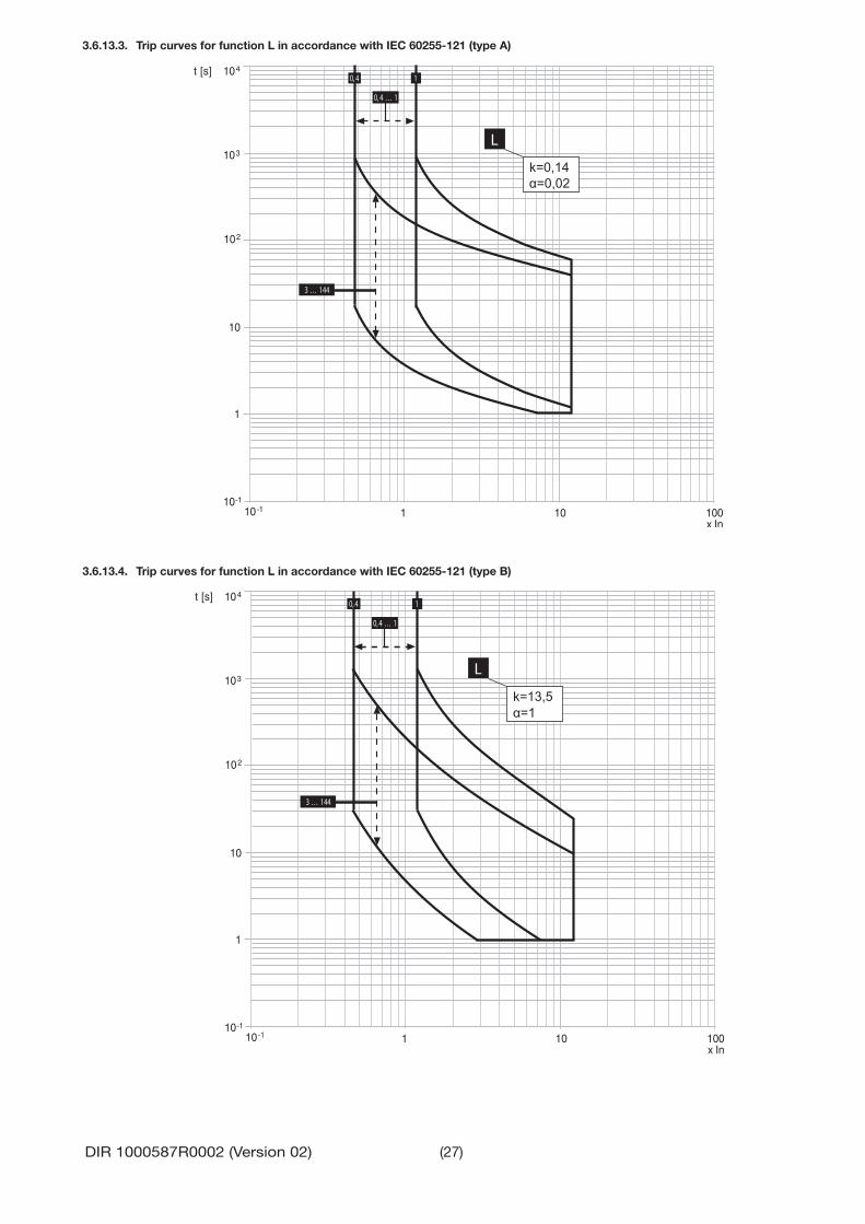
3.6.13.3. Trip curves for function L in accordance with IEC 60255-121 (type A)
t [s]
10-1
1
10
102
103
104
10-1 1 10 100x In
3 … 144
0,4 … 1
0,4 1
L
k=0,14α=0,02
3.6.13.4. Trip curves for function L in accordance with IEC 60255-121 (type B)
t [s]
10-1
1
10
102
103
104
1 10 10010-1x In
0,4 … 1
10,4
3 … 144
L
k=13,5α=1

(28)DIR 1000587R0002 (Version 02)
3.6.13.5. Trip curves for function L in accordance with IEC 60255-121 (type C)
t [s]
10-1
1
10
102
103
104
1 10 10010-1x In
0,4 … 1
0,4 1
3 … 144
L
k=80α=2
3.6.13.6. Trip curves for function G

(29)DIR 1000587R0002 (Version 02)
3.6.13.7. Trip curves for function U
t [s]
1 1010-1
1
10
102
103
104
10 -2
x In10 -1
0,02
0,5
100,5 … 60
0,9
60
0,02 … 0,9
U
3.7. Measuring functionsLSIG-MM include various measuring functions.The basic measurements available in all models are: - Currents: three phases (L1, L2, L3), neutral (N) and earth fault - Trips (last 20) and events (last 80) - Log register: storage of maximum current reading (with the date and time of recording) - Peak factors: three phases (L1, L2, L3) and neutral (N) - Percentage of contact wear.
3.7.1. Runtime measurements: current, voltage, powerThe main current, measurements can be accessed by using the UP and DOWN buttons from the default page.In the default page, histograms with the currents appear on the display, while the value and the highest phase are also given in the numerical format.
The following current measurements are available:- Three-pole CB: phase currents I1, I2, I3 are available- Three-pole CB, confi guration with external neutral (3P+N): phase currents I1, I2, I3, Ine are available- Four-pole CB: phase currents I1, I2, I3, Ine are available
The runtime measurement tolerance margins are:
Type of measurement range Range of values measured by the trip unit
Standard operationRange Tolerance %
Phase and neutral currents 0.05 ... 16In 0.3 ... 6 In ± 1.5Internal ground fault current 0.05 ... 16In 4In 0.3 ... 4 In ± 1.5

(30)DIR 1000587R0002 (Version 02)
3.7.2. TripThe list of trips recorded by the tip unit is available in the Measurements-Log Files-Openings section. Information about the last trip is also available from the main page by pressing the iTest button three times.Each trip is recorded with useful information enabling it to be identifi ed:
n. 02
L Protection
I1: 625 A I3: 623 A
I2: 617 A Ne: > 10.0 kA
Jan 06, 2004 08:52:11:733
Last Trip Number of trips: nr01 is the latest; maximum 20 trips
Currents recorded at trip time
Tripped protectionDate and time of trip
Use the UP and DOWN buttons to scroll all the trips recorded in the Openings menu.
ATTENTION: After a trip has occurred, the page with the recorded trip appears on the display. Press iTest to remove it and go back to the main page.
ATTENTION: with the trip unit off after a trip has occurred, press the itest button to display the page with the recorded trip for a few seconds. The trip will be displayed for approximately 48 hours, because the trip unit is self powered. To maintain the trip status beyond 48 hours, the use of a separate 24V DC power source is recom-mended.
3.7.3. EventsThe list of trips recorded by the trip unit is available in the Measurements-Log Files-Events section. The page of each event is similar to that of the trips, with a description of the event instead of the message about the protection and numbering that refers to the last event recorded (Last, Last-1, Last-2,...).
LSIG-MM are able to record up to 80 events. Use the UP and DOWN buttons to scroll all the events.
3.7.4. Measurements Log registerLSIG-MM can record various different measurements and allow the recording time between one measurement and the next to be set.The measurements are available in the Measurements-Log Files-Measurements section:
Name Description
I Max Rms value and maximum current phaseReset measurements Meter reset command
Each measurement available is shown on the display by a graphic page:
Date and time of recorded measure
Value of selected measure
Type of measure
Selected recording time
Graphical representation of last 25 measures. Selected measure blinks
Use the UP and DOWN buttons to scroll all the recordings of each measurement.Select the Measurement reset command to reset all the recordings.The recording time can be adjusted in the Settings-Measurement interval menu.
3.7.5. Peak factorThe peak factor measurement, a ratio between Ipeak / Irms is available for each current phase.The measurement is not displayed if the current is less than 0.3xIn and is not available for currents exceeding 6xIn.
Type of measurement range Range of values measured by the trip unit
Standard operationRange Tolerance %
Peak factor 0.3 ... 6 In 0.3 ... 6 In ± 1.5
3.7.6. Contact wearThis sub-menu displays the percentage of wear on the CB contacts.

(31)DIR 1000587R0002 (Version 02)
3.8. Main functions3.8.1. WatchdogLSIG-MM provide certain watchdog functions able to ensure that CB and trip unit faults are managed properly. These functions are as follows: - Watchdog for presence of Auxiliary power supply with “plug” icon displayed. - RATING PLUG validity. - Watchdog for proper connection of the current sensors (CS). If it is enabled, any anomalies are indicated by a special alarm message and the “alarm” LED coming on, and the circuit-breaker opens after 1s.
- Watchdog for proper connection of the Trip Coil (TC). If it is enabled, any anomalies are indicated by a special alarm message and the “alarm” LED coming on.
3.8.2. Circuit-breaker stateLSIG-MM detect the state of the circuit-breaker by means of specifi c wiring in the CB itself. When the presence of current is de-tected with the circuit-breaker “OPEN”, state error is signalled by means of a warning message and the “warning” led comes on.
3.8.3. Function MMLSIG-MM has a pair of input and output contacts for managing protection MM, described in par. 3.6.10: - K14/K15: input for activating protection MM;
The voltage applied between K14 (+) and K15 (-) establishes the state of the protection: - 0..2Vdc protection deactivated. - 15..24Vdc protection activated.
Consumption @24Vdc= 3mA max. - 95S/98S: the output supplies the state of protection MM:
- If the protection is active, the contact is closed; - If the protection is deactivated, the contact is open.
The contact is available in all supply confi gurations and possesses the following electrical characteristics:
Type of contactMaximum switching voltage 400 Vac (Peak) / VdcMaximum switching current 0.1 Aac (Peak) / AdcMaximum switching power 40 W
Contact/Circuit insulation 1500 Vac
ATTENTION: -Upon powering, and if there is already energizing voltage on the input contact, the output contact closes within
100 ms. -Following a trip through protection MM, the output contact can open temporarily for up to 20ms.
3.9. Settings MenuThe Settings menu contains various different settings for trip unit operation and for confi guring the installation in the correct way.7 options are available:
Settings Menu Options Description
1. Circuit breaker Enabling and adjustment of the Neutral protection, earth protection and the installation commands2. Mains frequency Adjustment of the frequency of the installation3. Measurement interval Adjustment of the measurement interval for the log fi le4. System Date, time, language, password settings5. Display Contrast Adjustment of the display contrast
3.9.1. Circuit-breakerThis area allows you to: - Enable the Neutral protection (ON/OFF) and adjust its control level (50%- 100% - 200%). All the details about the operating mode are given in the description of the Neutral protection, in par. 3.6.9.
- Perform the installation and uninstalling operations for the trip unit in the CB. Instructions for correct installation are given in par. 3.11.1 and 3.11.2.
3.9.2. Network frequencyThis area allows you to enter the frequency of the installation: 50Hz or 60Hz.Selection of this parameter allows the trip unit to calibrate its protection and measurement functions according to the value chosen by the user.
3.9.3. Measurement IntervalThe storage time for the measurements log fi le can be adjusted in the Settings-Measurement Interval menu. Further details about the measurements function are given in par. 3.7.4.

(32)DIR 1000587R0002 (Version 02)
3.9.4. SystemThe date and time of the trip unit, the Language and Password can be adjusted in the Settings-System menu.
3.9.4.1. LanguageWhen selecting the system language, make sure that:- the CB is open;- 24V DC supply or 140G-ELBU is present.The trip unit will not allow the language to be changed in the absence of one of the above conditions.
3.9.4.2. PasswordLSIG-MM is supplied with the default password: 0001.The password, which is required if all the changes to the protections or settings in the trip unit are to be saved, can be changed in the Settings-System-New Password menu. The values that can be used in the password range from 0000 to 9999.
To change the PW, fi rst enter the old one, then select the 4 new fi gures: the value of each fi gure can be chosen with the UP and DOWN keys. Use ENTER to confi rm the fi gure and pass on to the next one.The password is checked after the fourth fi gure has been entered. The procedure will change from the “READ” state to the “EDIT” state if the password is correct.
The password prompt is disabled by setting the value of the password to [0000] (in the “System Confi guration” menu). It is therefore always possible to switch from “READ” to “EDIT”.
ATTENTION: The password is valid for up to two minutes from the last time a key was pressed. After that time, it must be entered again so as to validate any changes or to access the menus.
3.9.5. Display contrastThe degree of contrast on the display can be adjusted in the Settings-Display Contrast menu.
3.10. Test MenuThe Test menu provides various options for checking the trip unit and CB.
Up to 5 options are available:
Name Description
1. CB status allows the user to view the CB state read by the trip unit.2. Auto Test allows the display and led test to be performed3. Trip test allows an opening command to be transmitted to the CB4. MM Test module allows output 95S/98S to be checked and the state of K14/K15
3.10.1. AutotestWhen autotest is activated, the display and leds will perform a test procedure allowing the user to check the state of the display and operation of the leds themselves. The procedure lasts several seconds and the sequence is as follows:
Phase ALARM and WARNING leds Display
1 On and fi xed The words “ALLEN - BRADLEY” and a message with the name of “LSIG-MM”2 Off Flashing backlighting (only if 24V DC supply is present)3 Normal operation Contrast from 100% (display dark) to 0% (display light), after which the words and
logo reappear
The test result and assessment are at the user’s discretion. Inform AB if faults occur (Leds fail to function, display areas that fail to function correctly).
3.10.2. Trip testThe state of CB opening can be checked by activating the trip test. The trip unit sends a command to the CT, which activates a CB opening mechanism. Opening of the circuit-breaker denotes a positive test result.
ATTENTION: To perform the trip test, there must be no current circulating and the CB must be closed (failing this, the Exception 6 error will appear).
3.10.3. MM TestThe test menu is available with the MM trip unit version. 2 possible options can be selected:- Auto Test causes contacts 95s/98s to close for 1s.- Input allows the state of inputs K14/K15 to be verifi ed: On for > 15 VDC voltage values, Off for < 2 VDC voltage values.The verifi cations and test setup are at the user’s discretion and must comply with the maximum limits of the inputs and outputs.

(33)DIR 1000587R0002 (Version 02)
3.11. Putting into service and recommendations
3.11.1. InstallationCircuit-Breakers purchased with the trip unit assembled do not require this operation which is, however, necessary in the case of replacement.Comply with the following instructions if the trip unit on the CB is replaced:
1. With the circuit-breaker open and possibly isolated, install the trip unit on the circuit-breaker2. Power the trip unit with battery unit only3. If there are no other errors, the display will show the message Confi guration (confi guration error) accompanied by the yellow
LED coming on permanently (warning)4. Enter the unit’s “Settings” menu5. Select “Circuit-breaker”6. Select “Unit installation”7. Input the password8. Select “Install” and press “ENTER”9. When the red led fl ashes on and off and the message Installation (installation error) is displayed, remove the battery unit10. Energize the trip unit from any other source11. Check for the absence of confi guration errors.
3.11.2. UninstallingTo complete the procedure for uninstalling a LSIG-MM unit, follow the steps below:
1. With the circuit-breaker open and/or isolated, power the trip unit with battery unit2. Enter the unit’s “Settings” menu3. Select “Circuit-breaker”4. Select “Unit installation”5. Input the password6. Select “Uninstall” and press “ENTER”7. Remove the battery unit8. Remove the LSIG-MM unit from the circuit-breaker9. The remove the TC connector, proceed as indicated in the fi gure alongside.
The uninstalling procedure is not strictly necessary for operation but is strongly recommended as it allows allows circuit-breaker parameters such as contact wear and others that would otherwise be lost, to be stored. The data in question are then re-transmitted to the new trip unit to be installed in the same circuit-breaker.
3.11.3. ConnectionsATTENTION: For the connections provided by the user, it is recommended that you comply strictly with the recommendations contained in this document. This will ensure compliance with all the international reference standards and guarantee that the trip unit functions perfectly even in heavy duty environmental and electromag-netic conditions.
Pay particular attention to the types of cable, the connections to earth and the maximum distances.
3.11.4. CS and TC connection testATTENTION: If LSIG-MM has been installed by the user, it is important, before closing the CB, to check the last line on the display when the trip unit is turned on for the fi rst time via battery unit module. No CS and/or TC disconnected messages must appear; if they do, do not close the circuit-breaker and make the correct connec-tions.
3.11.5. Current sensor connection for external neutralATTENTION: If you want to connect the current sensor for the external neutral conductor to a three-pole circuit-IMPORTANT, remember to set InN. accordingly. During this procedure, the circuit-breaker must be open and preferably isolated.

(34)DIR 1000587R0002 (Version 02)
3.11.6. Default parametersBefore LSIG-MM is put into service, it is essential for the user to defi ne and carefully adjust the editable parameters to suit the installation requirements.AB will apply the adhesive rating plates of all the variables concerning the CB (e.g. Type of CB, Rating Plug size, etc.), thereby allowing the user to fi nd the information he needs when defi ning the parameters.
ATTENTION: Apart from this, it is essential for the user to change the password and carefully defi ne each edit-able parameter before putting the trip unit into service.
LSIG-MM are supplied with the following predefi ned parameters:
Protection On/Off Thresholds Time Curve TripL -- 1 In 144 s I2t --S Off 6 In 50 ms K --I On 4 In -- -- --G Off 0.2 In 0.4 s K OnU (currents) Off 50 % 5 s OffOT -- OffK LC1 Off 50 % I1K LC2 Off 75 % I1Language -- EnglNet Frequency -- 50 HzNeutral sel. -- *S startup Off 6 In 100 msG startup Off 1 In 100 msPassword -- 0001Measuring interval -- 60 minIw Off 3 InWarning: harmonic distortion OffStart up activation threshold 0.1InMM On 2.5 In
NOTES:* = OFF for three-pole versions* = 50% for four-pole versions* = 100% for full size versions

(35)DIR 1000587R0002 (Version 02)
3.12. Troubleshooting
3.12.1. TroubleshootingThe following table lists a series of typical service conditions, to help you understand and solve hypothetical faults or malfunctions.
NOTES: 1. Before consulting the following table, check for any error messages appearing for some seconds on the display.2. If the suggestions do not help in resolving the problem, please contact your Rockwell Automation technical support team.
N° Situation Possible causes Suggestions
1 The trip test cannot be run 1. The busbar current is > 02. The TC is not connected
1. Verify current is not present to the trip unit
2. Check the messages on the display2 Trip times lower than
expected1. Threshold is set too low2. Time is set too low3. Thermal memory enabled4. Incorrect Neutral Selection
1. Adjust threshold2. Adjust time3. Exclude if not necessary4. Correct Neutral Selection
3 Trip times higher than expected
1. Threshold is set too high2. Time is set too high3. Curve I2t inserted4. Incorrect Neutral Selection
1. Adjust threshold2. Adjust time3. Exclude if not necessary4. Correct Neutral Selection
4 Rapid trip, with I3=Off Current above I3 override value Verify the cause of high current condition5 High earth fault current, but
no trip happens1. Incorrect selection of the sensor 2. Function G prevented with I>4In
1. Set int. or ext. sensor2. Set function with I>4In
6 Display off 1. 24V DC supply missing and the current is below the minimum value.
2. Operating temperature out of range
1. See par. 3.4.3
2. See par. 3.3.7 and see par. 3.6.77 Reading of I incorrect Current below the minimum threshold that
can be displayedVerify current with a meter
8 Message “” instead of expected data
Function disabled or data off range Verify protection function and settings
9 The expected trip does not occur
Trip function disabled Enable trip if necessary
10 No activation of the Unbalance U protection
Values of I out of range See par. 3.6.6
11 No display of trip data 24V DC supply missing, the buffer capacitor is discharged
See par. 1.7.2
12 The password is not requested
The password has been disabled Re-enter the password with a value other than 0000
13 Impossible to change any parameter
LSIG-MM is activated Parameter ara not adjustable when MM is activated
14 “ Temp. sensor” or “ Start-up” message
Possible fault inside the trip unit Contact Rockwell Automation Technical Support
15 Invalid date 1. First installation2. Information lost due to power failure
Change date, see par. 3.9.4
16 Untimely trip See par. 3.4.3.217 LED lighting See par. 3.4.118 The language cannot be
changed1. The trip unit is confi gured in the remote
mode 2. CB not open3. 24V DC supply or battery unit not
installed
1. Set locally2. Open CB3. Power the trip unit
19 The activation contact of protection MM is not closed
Protection MM has not been enabled or K14/15 has no incoming signal
Check the menu to make sure that the protection is enabled and use a tester to check that voltage and polarity at the ends of K14 and K15 are correct

(36)DIR 1000587R0002 (Version 02)
3.12.2. In the case of a fault
ATTENTION: If you suspect that the trip unit is faulty, functions incorrectly or has generated an unwanted trip, you are strongly advised to strictly comply with the following instructions in Measurements menu Historicals Trip:
1. Make a note of the type of protection that has tripped by accessing the LAST TRIP page if there is an external power supply (24V DC supply or battery) or by pressing “i Test” if in self-powering mode.
2. Record the type of circuit-breaker, number of poles, any accessories connected, In, Serial Number (see par. 14.4) and the SW version.
3. Prepare a brief description of the opening (what LEDs and/or indications were displayed? when did it happen?, how many times ?, was it always under the same conditions? what type of load? what voltage? what current? is the event reproducible?)
4. Send/communicate all the information collected, together with the circuit diagram for the circuit-breaker, to your nearest AB Customer Support service.
The completeness and accuracy of the information given to the Rockwell Auotmation Technical Support will facilitate technical analysis of the problem encountered, and will allow us to carry out all actions useful for the user rapidly.
ATTENTION: Letting a switch run with a fault that has not been remedied may lead to an apparatus malfunction or shutdown. Remove the apparatus immediately until it can be inspected or repaired. This situation may lead to personal injury or property damage.
4. ACCESSORIES
4.1. External neutralThis is a current sensor for the external neutral pole of the circuit-breaker, designed to provide neutral protection for three-pole circuit-breakers. Further details about connection of the external neutral are available in document 1000529R0513.
4.2. Rating PlugThe rating plug defi nes the rated current In, which is essential for regulating the protections. This is because the regulation of all the protections refers to In (e.g.: I1= 0.4 xIn).The rating plug is installed in the trip unit, on a dedicated front connector and is available to the user. The trip unit can be equipped with various different Rating Plug models, up to value Iu (uninterrupted rated cur-rent Iu of the CB given on the rating plate of the front guard).Example: CB 140G-N 800 has Iu= 800 A, and can be fi tted with a rating plug with In 800A.
The module is interchangeable, with the trip unit off and the CB open.
The trip unit continuously checks for the presence of the rating plug and signals its absence or any assembly errors.
ATTENTION: Replacement of the rating plug with the trip unit on or the CB closed could lead to faulty trip unit operation or undesired opening of the CB.
4.3. Battery Unit (140G-ELBU)Battery unit is an external unit allowing the trip unit to be energized so that Installation, Autotest and Trip Test can be performed, along with verifi cations with the CB open. The unit is connected to the trip unit by means of the front service connector.
At the end of its life, this equipment should be collected separately from any unsorted municipal waste

Copyright © 2017 Rockwell Automation, Inc. All Rights Reserved. Printed in Italy.
Allen-Bradley, Rockwell Software, and Rockwell Automation are trademarks of Rockwell Automation, Inc.
Trademarks not belonging to Rockwell Automation are property of their respective companies.
Rockwell Automation maintains current product environmental compliance information on its website at http://www.rockwellautomation.com/rockwellautomation/about-us/sustainability-ethics/product-environmental-compliance.page
DIR 1000587R002 Version 02 (B0431) - B1475
Pubblication 140G-IN067C-MU-P - September 2017

MATERIALSIZE
FOLD
TO BE DETERMINEDBY STRATEGIC PARTNER
TO BE DETERMINEDBY STRATEGIC PARTNER
TO BE DETERMINEDBY STRATEGIC PARTNER
FLAT
This Instruction Sheet is Being Printed by Strategic Partner
Note: After folding---Printed in (Country where printed)* and instruction sheet number in lower left corner should be visible.
* The printing vendor may change the instruction sheet files to show the correct country.