direct drive industrial atomisers - micron group · direct drive industrial atomisers...
TRANSCRIPT

DIRECT DRIVE INDUSTRIAL ATOMISERS
Operator's Handbook
and
Parts Catalogue Micron Sprayers Limited Bromyard Industrial Estate Bromyard Herefordshire HR7 4HS United Kingdom Tel: (01885) 482397 +44 1885 482397 Fax: (01885) 483043 +44 1885 483043 E-mail: [email protected] Iss 9W Web site: www.micron.co.uk 08/18
TABLE OF CONTENTS 1. INTRODUCTION.................................................................................. 1 2. OPTIONS ............................................................................................. 1 3. PART NUMBERS................................................................................. 2 4. SPECIFICATION.................................................................................. 3
4.1 Direct Drive Atomiser Assembly ................................................ 3 4.2 Atomiser in Cowl with Air Circulation Fan .................................. 3
5. INSTALLATION.................................................................................... 5
5.1 Mounting of Atomiser................................................................. 5 5.2 Mounting of Cowl with Air Circulation Fan ................................. 8 5.3 Electrical Installation .................................................................. 8 5.4 Inverter Drive Parameters........................................................ 10 5.5 Liquid Feed.............................................................................. 11
6. DROPLET SIZE ................................................................................. 11 7. HEALTH & SAFETY........................................................................... 14 8. MAINTENANCE ................................................................................. 14 9. PARTS LISTS ................................................................................... 16
9.1 Atomiser .................................................................................. 16 9.2 Cowl & Air Circulation Fan....................................................... 18
APPENDIX I – LIST OF INVERTER DRIVE PARAMETERS..................... 20
MICRONAIR DIRECT DRIVE INDUSTRIAL ATOMISERS
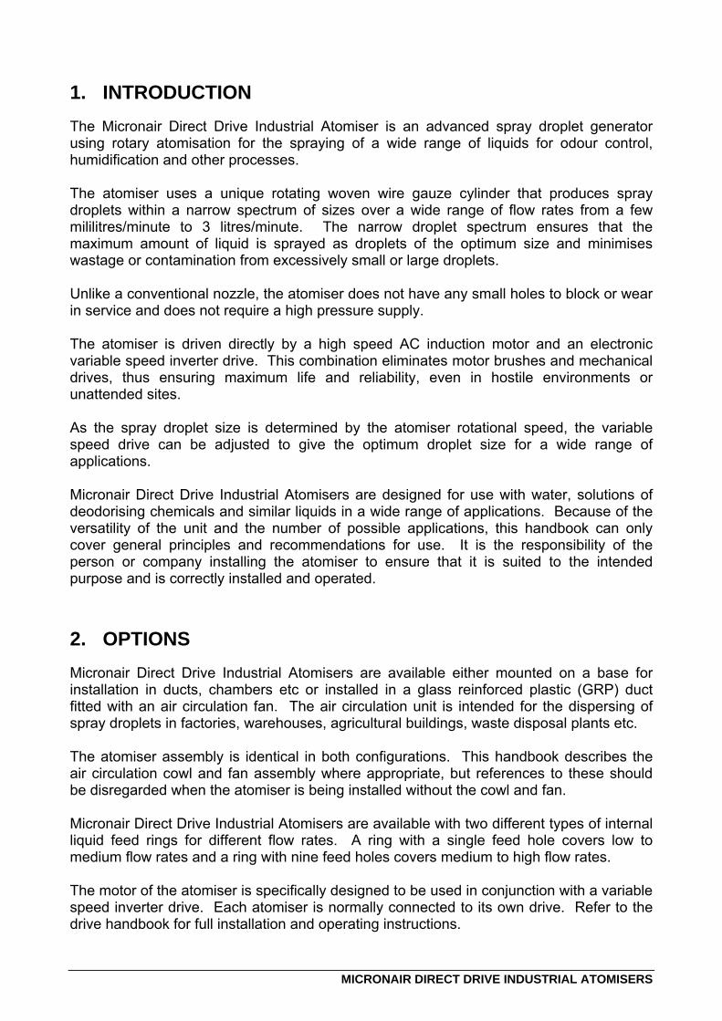
1. INTRODUCTION The Micronair Direct Drive Industrial Atomiser is an advanced spray droplet generator using rotary atomisation for the spraying of a wide range of liquids for odour control, humidification and other processes. The atomiser uses a unique rotating woven wire gauze cylinder that produces spray droplets within a narrow spectrum of sizes over a wide range of flow rates from a few mililitres/minute to 3 litres/minute. The narrow droplet spectrum ensures that the maximum amount of liquid is sprayed as droplets of the optimum size and minimises wastage or contamination from excessively small or large droplets. Unlike a conventional nozzle, the atomiser does not have any small holes to block or wear in service and does not require a high pressure supply. The atomiser is driven directly by a high speed AC induction motor and an electronic variable speed inverter drive. This combination eliminates motor brushes and mechanical drives, thus ensuring maximum life and reliability, even in hostile environments or unattended sites. As the spray droplet size is determined by the atomiser rotational speed, the variable speed drive can be adjusted to give the optimum droplet size for a wide range of applications. Micronair Direct Drive Industrial Atomisers are designed for use with water, solutions of deodorising chemicals and similar liquids in a wide range of applications. Because of the versatility of the unit and the number of possible applications, this handbook can only cover general principles and recommendations for use. It is the responsibility of the person or company installing the atomiser to ensure that it is suited to the intended purpose and is correctly installed and operated.
2. OPTIONS Micronair Direct Drive Industrial Atomisers are available either mounted on a base for installation in ducts, chambers etc or installed in a glass reinforced plastic (GRP) duct fitted with an air circulation fan. The air circulation unit is intended for the dispersing of spray droplets in factories, warehouses, agricultural buildings, waste disposal plants etc. The atomiser assembly is identical in both configurations. This handbook describes the air circulation cowl and fan assembly where appropriate, but references to these should be disregarded when the atomiser is being installed without the cowl and fan. Micronair Direct Drive Industrial Atomisers are available with two different types of internal liquid feed rings for different flow rates. A ring with a single feed hole covers low to medium flow rates and a ring with nine feed holes covers medium to high flow rates. The motor of the atomiser is specifically designed to be used in conjunction with a variable speed inverter drive. Each atomiser is normally connected to its own drive. Refer to the drive handbook for full installation and operating instructions.
2
MICRONAIR DIRECT DRIVE INDUSTRIAL ATOMISERS
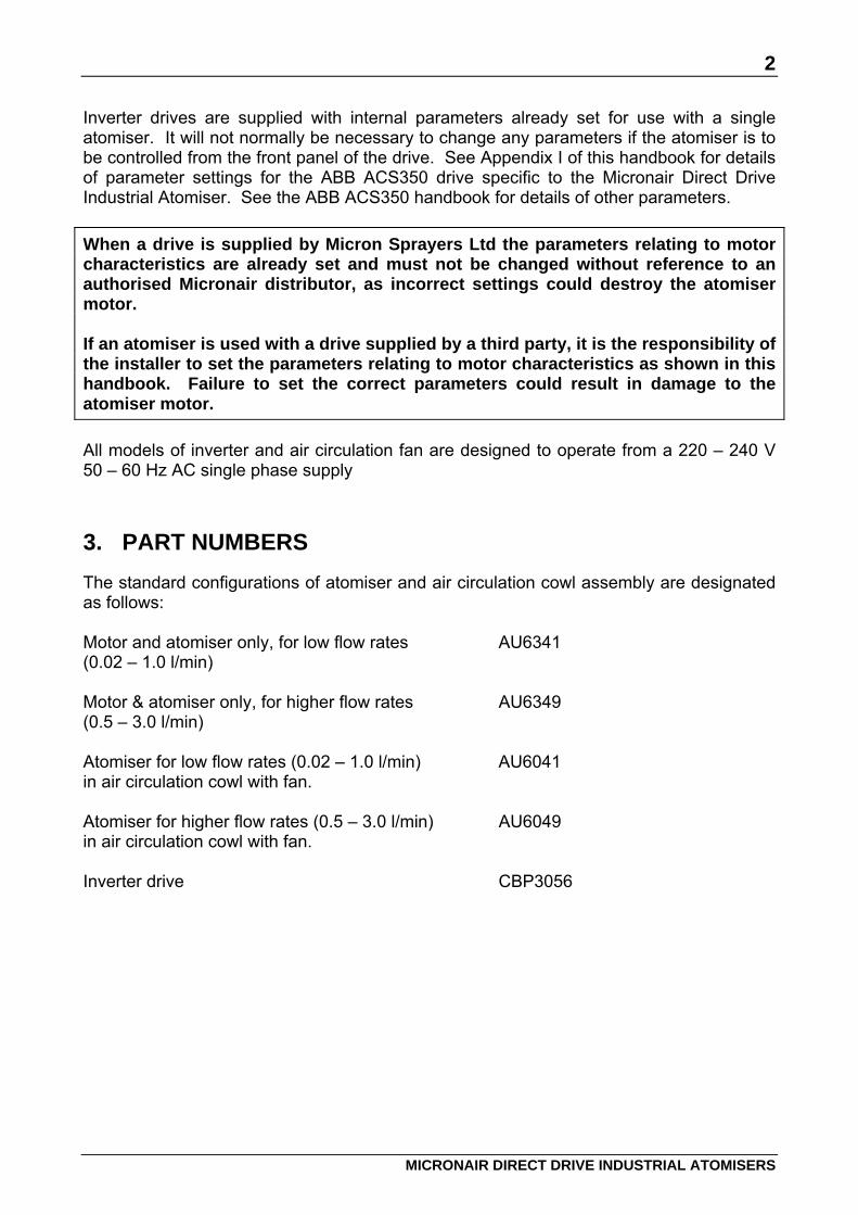
Inverter drives are supplied with internal parameters already set for use with a single atomiser. It will not normally be necessary to change any parameters if the atomiser is to be controlled from the front panel of the drive. See Appendix I of this handbook for details of parameter settings for the ABB ACS350 drive specific to the Micronair Direct Drive Industrial Atomiser. See the ABB ACS350 handbook for details of other parameters. When a drive is supplied by Micron Sprayers Ltd the parameters relating to motor characteristics are already set and must not be changed without reference to an authorised Micronair distributor, as incorrect settings could destroy the atomiser motor. If an atomiser is used with a drive supplied by a third party, it is the responsibility of the installer to set the parameters relating to motor characteristics as shown in this handbook. Failure to set the correct parameters could result in damage to the atomiser motor. All models of inverter and air circulation fan are designed to operate from a 220 – 240 V 50 – 60 Hz AC single phase supply
3. PART NUMBERS The standard configurations of atomiser and air circulation cowl assembly are designated as follows: Motor and atomiser only, for low flow rates AU6341 (0.02 – 1.0 l/min) Motor & atomiser only, for higher flow rates AU6349 (0.5 – 3.0 l/min) Atomiser for low flow rates (0.02 – 1.0 l/min) AU6041 in air circulation cowl with fan. Atomiser for higher flow rates (0.5 – 3.0 l/min) AU6049 in air circulation cowl with fan. Inverter drive CBP3056
3
MICRONAIR DIRECT DRIVE INDUSTRIAL ATOMISERS
4. SPECIFICATION
4.1 Direct Drive Atomiser Assembly
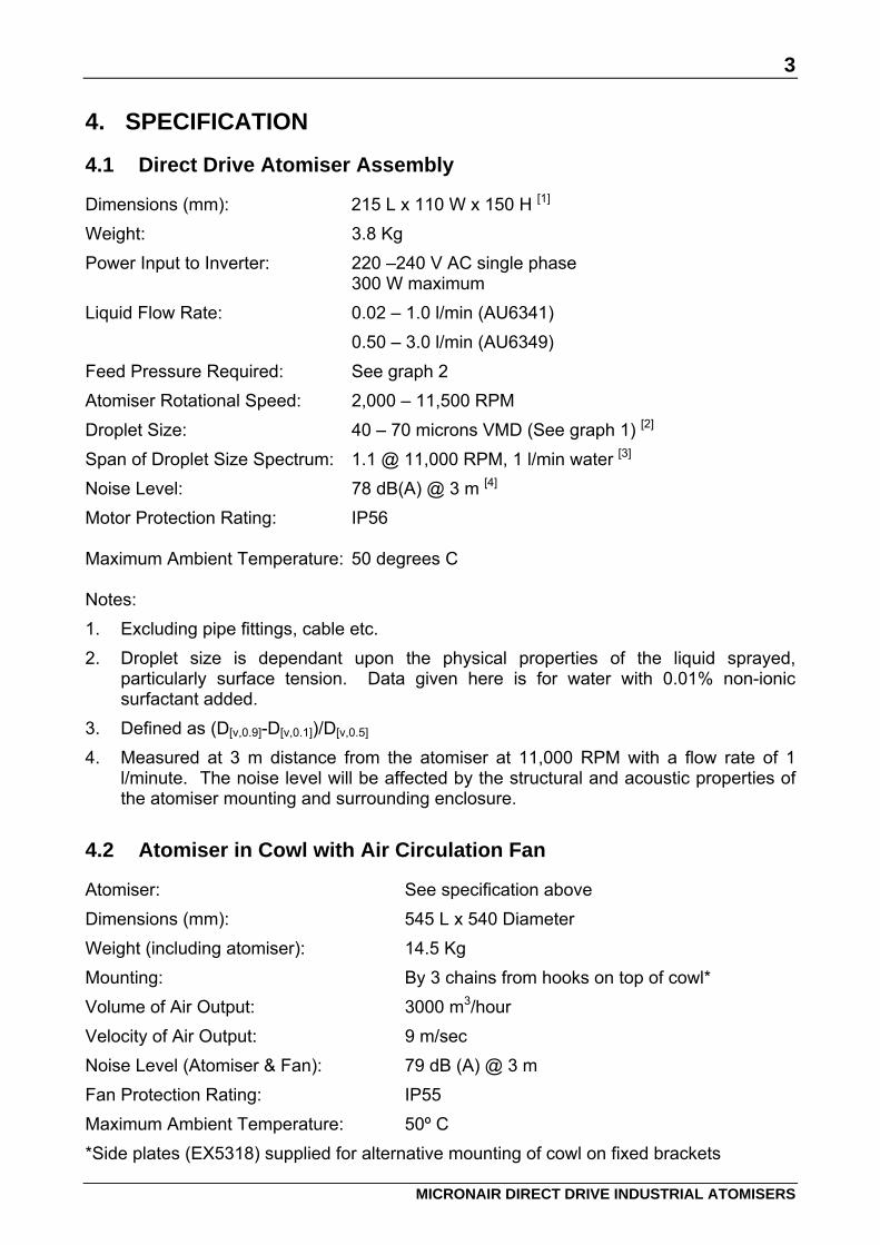
Dimensions (mm): 215 L x 110 W x 150 H [1] Weight: 3.8 Kg Power Input to Inverter: 220 –240 V AC single phase 300 W maximum Liquid Flow Rate: 0.02 – 1.0 l/min (AU6341) 0.50 – 3.0 l/min (AU6349) Feed Pressure Required: See graph 2 Atomiser Rotational Speed: 2,000 – 11,500 RPM Droplet Size: 40 – 70 microns VMD (See graph 1) [2] Span of Droplet Size Spectrum: 1.1 @ 11,000 RPM, 1 l/min water [3] Noise Level: 78 dB(A) @ 3 m [4] Motor Protection Rating: IP56 Maximum Ambient Temperature: 50 degrees C Notes: 1. Excluding pipe fittings, cable etc. 2. Droplet size is dependant upon the physical properties of the liquid sprayed,
particularly surface tension. Data given here is for water with 0.01% non-ionic surfactant added.
3. Defined as (D[v,0.9]-D[v,0.1])/D[v,0.5] 4. Measured at 3 m distance from the atomiser at 11,000 RPM with a flow rate of 1
l/minute. The noise level will be affected by the structural and acoustic properties of the atomiser mounting and surrounding enclosure.
4.2 Atomiser in Cowl with Air Circulation Fan
Atomiser: See specification above Dimensions (mm): 545 L x 540 Diameter Weight (including atomiser): 14.5 Kg Mounting: By 3 chains from hooks on top of cowl* Volume of Air Output: 3000 m3/hour Velocity of Air Output: 9 m/sec Noise Level (Atomiser & Fan): 79 dB (A) @ 3 m Fan Protection Rating: IP55 Maximum Ambient Temperature: 50º C *Side plates (EX5318) supplied for alternative mounting of cowl on fixed brackets

4
MICRONAIR DIRECT DRIVE INDUSTRIAL ATOMISERS
Fig.1 – Micronair Direct Drive Industrial Atomiser
Fig. 2 – Micronair Direct Drive Industrial Atomiser with Air Circulation Fan

5
MICRONAIR DIRECT DRIVE INDUSTRIAL ATOMISERS
5. INSTALLATION It is the responsibility of the person or company installing the atomiser to ensure that all electrical, mechanical and safety aspects of the installation comply with the relevant customer, industry and national specifications. Atomisers and air circulation cowls must only be installed in environments that are compatible with the protection ratings of the equipment and the materials used. Micron Sprayers Ltd can accept no responsibility for damage resulting from acidic, alkaline, salt laden or other hostile environments. IMPORTANT: Neither the Micronair Direct Drive Atomiser nor the air circulation fan are designed for use in explosive atmospheres. This equipment must not under any circumstances be installed in atmospheres designated as presenting an actual or anticipated explosion hazard. The components of the atomiser are not intended to come into direct contact with foodstuffs or other products in the food processing industry. IMPORTANT: The atomiser uses a rotating gauze to produce spray droplets. The gauze can cause serious injury if it is touched whilst it is in motion. It is the responsibility of the installer of the equipment either to mount the atomiser in a position where it cannot be reached whilst in operation or to provide sufficient guards, enclosures, interlocks or other measures to eliminate the possibility of accidental contact with the rotating atomiser.
5.1 Mounting of Atomiser
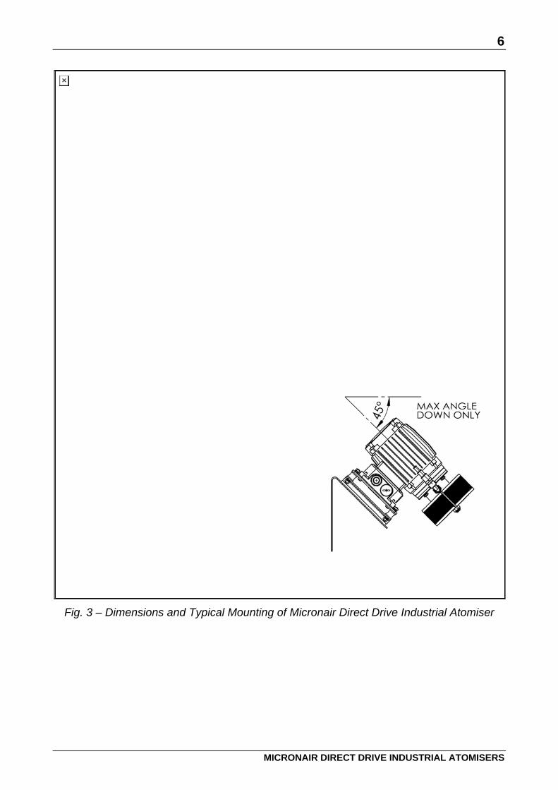
The atomiser is provided with a mounting base attached to the motor by anti-vibration mountings to minimise noise and vibration. Wherever possible, the mounting base should be bolted to a suitable support structure. Where this is not practical, the base may be discarded and the anti-vibration mountings fitted directly to the customer's own support. It is, however, vital that the anti-vibration mountings are always used. The axis of the motor shaft should be horizontal or inclined at an angle of not more than 45 degrees with the atomiser gauze below the horizontal. The atomiser gauze should never be above the horizontal to prevent possible contamination of the motor bearings (see Fig. 3). If the atomiser is mounted in a duct or similar enclosure, the unit must be placed sufficiently far from the walls to avoid them being wetted with spray droplets. This distance will depend upon the air velocity in the duct but will be typically 0.5 m with an air velocity of 5 m/second.
6
MICRONAIR DIRECT DRIVE INDUSTRIAL ATOMISERS
Fig. 3 – Dimensions and Typical Mounting of Micronair Direct Drive Industrial Atomiser
7
MICRONAIR DIRECT DRIVE INDUSTRIAL ATOMISERS
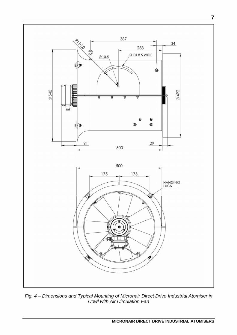
Fig. 4 – Dimensions and Typical Mounting of Micronair Direct Drive Industrial Atomiser in
Cowl with Air Circulation Fan

8
MICRONAIR DIRECT DRIVE INDUSTRIAL ATOMISERS
5.2 Mounting of Cowl with Air Circulation Fan
The cowl of the air circulation fan is designed to be suspended from a ceiling or structure by means of three chains attached to hooks at the top of the cowl. The chains must have a minimum safe working load of 50 Kg each. The lengths and angles of the chains must be chosen to ensure that the axis of the cowl is horizontal and that the outlet (atomiser) end faces in the direction in which the spray droplets are to be blown. The outlet of the cowl should be directed well clear of any walls, obstructions or electrical equipment which could be wetted by the spray droplets. The inlet (fan) end of the cowl must be a minimum of 1 m away from any wall or vertical obstruction to ensure an unrestricted airflow. 5.3 Electrical Installation
The inverter drive must be installed in a suitable cabinet or enclosure to meet the relevant requirements for environmental protection and safety. Full instructions for the mounting of the inverter are given in the manufacturer's handbook supplied with the unit. This handbook also gives minimum requirements for adequate cooling of the inverter. IMPORTANT: Neither Micron Sprayers Ltd nor the inverter manufacturer can accept any responsibility for damage resulting from an inverter installation which does not comply with the manufacturer's recommendations. The ABB ACS350 inverter drive available from Micron Sprayers Ltd complies with European EMC standards as described in the drive handbook. It is the responsibility of the installer to follow the instructions in the drive handbook and to provide any additional filtration etc as may be required to achieve an EMC compliant installation. The connection between the driver and atomiser motor must be made with screened four core cable with the following minimum specification: Cable runs of less than 25 m 1.0 mm2 conductors Cable runs of more than 25 m 1.5 mm2 conductors The absolute maximum length of cable from the inverter drive to an atomiser is 100 m. The specification of the motor cable the method of termination of the screen must be in accordance with the details given in the drive handbook. The insulation material and construction of the power supply and motor cables must be chosen to comply with the requirements of the environments in which they are installed. All items must be earthed in accordance with applicable electrical installation regulations and codes of practice. The atomiser motor is supplied with a screened flying lead 5 metres long.

9
MICRONAIR DIRECT DRIVE INDUSTRIAL ATOMISERS
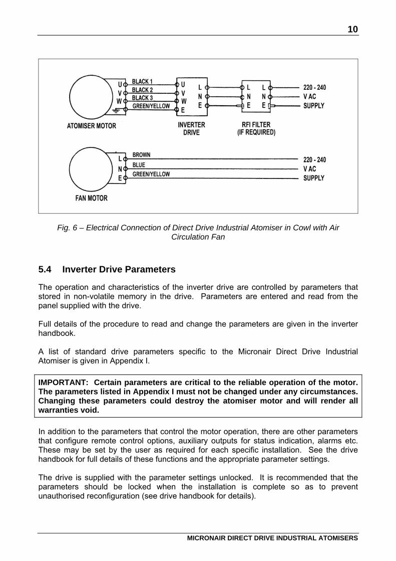
IMPORTANT: The motor cable must always be run downwards from the motor terminal box. This is to prevent liquid running down the cable and into the motor. If the cable must be run from a point above the motor, it should be formed into a loop below the level of the motor gland. The schematic wiring diagram of a typical installation of an atomiser is shown in Fig 5. The schematic wiring diagram of a typical installation of an atomiser and air circulation fan is shown in Fig. 6. Note that the fan must be connected to a 50 – 60 Hz single phase AC mains supply and not to the inverter output. Note that the three wires for the motor phases are coloured black and numbered 1, 2 & 3. These correspond to the standard U V W designation as follows (see also Figs 5 & 6): On atomisers manufactured before November 2007 these wires were coloured black, brown and grey. Phase U Black 1 (Black*) Phase V Black 2 (Brown*) Phase W Black 3 (Grey*)
Note: Wire colours denoted * used on atomisers manufactured before November 2007.
The motor earth wire is coloured green/yellow and must be connected to an appropriate earth bonding point in accordance with applicable electrical installation regulations. On completion of the installation, the direction of rotation of the atomiser must be checked. The atomiser should rotate clockwise (as viewed on the gauze end) with the drive set to run the motor forward. If the atomiser should rotate anti-clockwise, either the inverter is set to run the motor in reverse or two of the phases feeding the motor have been reversed (eg U → V, V → U etc). To change the direction of rotation, reverse any two of the motor wires.
Fig. 5 – Electrical Connection of Direct Drive Industrial Atomiser
10
MICRONAIR DIRECT DRIVE INDUSTRIAL ATOMISERS
Fig. 6 – Electrical Connection of Direct Drive Industrial Atomiser in Cowl with Air Circulation Fan
5.4 Inverter Drive Parameters
The operation and characteristics of the inverter drive are controlled by parameters that stored in non-volatile memory in the drive. Parameters are entered and read from the panel supplied with the drive. Full details of the procedure to read and change the parameters are given in the inverter handbook. A list of standard drive parameters specific to the Micronair Direct Drive Industrial Atomiser is given in Appendix I. IMPORTANT: Certain parameters are critical to the reliable operation of the motor. The parameters listed in Appendix I must not be changed under any circumstances. Changing these parameters could destroy the atomiser motor and will render all warranties void. In addition to the parameters that control the motor operation, there are other parameters that configure remote control options, auxiliary outputs for status indication, alarms etc. These may be set by the user as required for each specific installation. See the drive handbook for full details of these functions and the appropriate parameter settings. The drive is supplied with the parameter settings unlocked. It is recommended that the parameters should be locked when the installation is complete so as to prevent unauthorised reconfiguration (see drive handbook for details).
11
MICRONAIR DIRECT DRIVE INDUSTRIAL ATOMISERS
5.5 Liquid Feed
Liquid must be fed to the atomiser from a supply provided by the installer of the system. This will normally consist of a storage/mixing tank and a pump to deliver the liquid to the atomiser. This system must also provide a means of regulating the flow to the atomiser. This will normally be either a positive displacement dosing pump or a higher output centrifugal pump with a by-pass to the tank and a needle valve or similar flow restrictor to regulate the flow to the atomiser. If the atomiser is fed from the mains water supply, it may be necessary to take precautions to avoid the build-up of lime scale in the pump, pipework and atomiser. In areas with hard water, a suitable water softener must be installed in the feed to the mixing tank. Alternatively, de-mineralised water can be used instead of the mains supply. IMPORTANT: Any direct connection to a mains water supply must be made in accordance with local regulations. Non-return valves and other protective devices must be installed as required. The liquid inlet connection to the atomiser is by means of an adaptor screwed into a 1/8" BSP female pipe elbow. The standard adaptor supplied with the atomiser has a stepped hose tail for 1/4" (6 mm), 3/8" (10 mm) or 1/2" (13 mm) inside diameter flexible hose. This adaptor may be replaced with an alternative type if required. The liquid feed tube should enter the atomiser feed body at the side so that the drain hole in the body is at the bottom. As the atomiser produces spray droplets by the rotary action of the gauze, a high pressure is not necessary for its operation. The supply pressure need be adequate only to overcome the pressure drop along the feed hose, the static head due to the height of the atomiser above the pump and the pressure required to pass the required flow rate through the atomiser. The required pressure to pass a given flow rate through the atomiser is shown in Graph 2.
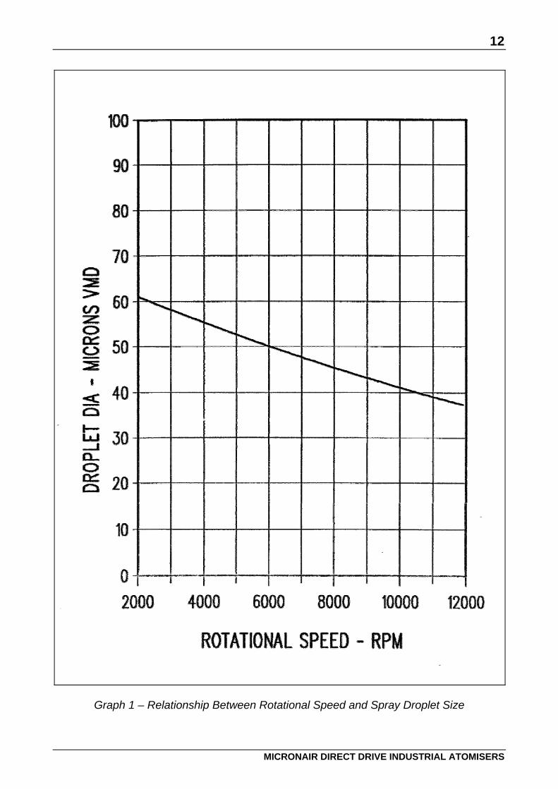
6. DROPLET SIZE The size of the spray droplets produced by a Micronair Direct Drive Industrial Atomiser depends upon the rotational speed of the gauze and the properties of the liquid being sprayed. Graph 1 shows the relationship between droplet Volume Median Diameter (VMD) and rotational speed for water. The droplet size produced with other liquids may differ from that shown for water. Surfactants or other additives that reduce the surface tension of water will tend to reduce the droplet size. The speed of the atomiser must be adjusted to give the required droplet size by varying the output frequency of the drive. A high atomiser speed will be required to produce small droplets that are necessary to remain airborne for humidification by evaporation or for odour control. A rotational speed of 10,000 RPM or more is recommended for these applications.
12
MICRONAIR DIRECT DRIVE INDUSTRIAL ATOMISERS
Graph 1 – Relationship Between Rotational Speed and Spray Droplet Size
13
MICRONAIR DIRECT DRIVE INDUSTRIAL ATOMISERS
Graph 2 – Relationship Between Input Pressure and Flow from Direct Drive Atomiser
14
MICRONAIR DIRECT DRIVE INDUSTRIAL ATOMISERS
A lower rotational speed will be required to produce larger, heavier droplets for other applications. The procedure to vary the drive frequency will depend upon whether an internal or external frequency reference is being used and whether the parameter lock is set. See the drive handbook for full details. Note that the drive display can show atomiser motor speed as well as frequency. This makes it possible to set the speed without using a tachometer on the gauze.
7. HEALTH AND SAFETY Micronair Direct Drive Industrial Atomisers are supplied to installers and original equipment manufacturers as components of an overall installation for humidification, odour control or other applications. As Micron Sprayers Ltd have no control over the end use of their product, it is the responsibility of the installer, equipment builder and/or user to ensure that the atomisers are installed and operated in accordance with all applicable national and industry standards. These include, but are not limited to, safety and machinery directives, EMC regulations, electrical wiring and installation regulations, mains water regulations and precautions and restrictions concerning the use of the products to be sprayed.
8. MAINTENANCE The Micronair Direct Drive Industrial Atomiser is designed for easy maintenance and cleaning. The procedure to dismantle the atomiser is as follows: 1. Remove the M8 nut from the end of the motor shaft and pull off the gauze/hub body
assembly. Take care not to lose the drive pin in the motor shaft and the spacer washer on shaft.
2. The gauze can be removed from the hub body for replacement or cleaning by removing the three countersunk screws.
3. The inner gauze can be removed from the inside of the hub body for cleaning by reaching inside the bore of the hub with a pair of long-nose pliers, gripping the free end of the gauze and winding it inwards.
4. Unscrew the feed ring from the end of the feed body. If the ring is more than finger tight, it may be unscrewed by wrapping a piece of cloth or rubber round it and gripping it gently with a pair of large pliers. Do not grip the ring directly with metal jaws.
5. The 'O' rings may be removed from the outside of the feed body by prying them out with a small screwdriver. Take care not to damage the edges of the 'O' ring grooves.
6. The atomiser feed body can be removed from the motor by removing the four M5 pan head screws. Take care not to damage or lose the 'O' ring seal.
15
MICRONAIR DIRECT DRIVE INDUSTRIAL ATOMISERS
7. The 'V' ring seal on the motor shaft can be removed by sliding it along the shaft away from the face of the separator plate.
8. The separator plate is a loose fit on the motor face and should be removed to reveal the inner motor V ring seal, which can be slid along the shaft for removal.
After dismantling the atomiser, clean all parts with a solvent for the product which has been sprayed, followed by clean water and detergent. Check all parts, especially the seals, for damage or wear and replace as necessary. Apply a light film of grease to the 'O' ring and 'V' ring seals and re-assemble the atomiser by reversing the dismantling procedure. Do not over-tighten the feed ring on the feed body. This should be screwed on finger-tight until the gap between the edge of the feed ring and the step on the body is just closed. If the inner motor 'V' ring seal on the motor shaft has been removed, it must be re fitted before positioning the separator plate on the atomiser. To ensure the correct position of the seal on the motor shaft, the 'V' ring should be pushed against the end cap of the motor until the rear face of the 'V' ring is 4.5 mm from the face of the motor end cap. Before attaching the atomiser feed body to the motor (sandwiching the separator plate), the separator plate bolt holes should be aligned with the motor holes (ensure that the slot machined in rear face of plate is orientated below motor shaft, to permit drainage) and the plate held firmly onto the motor face, whilst the secondary ‘V’ ring seal is located on the shaft (similar to the inner seal). The atomiser feed body should then be bolted onto the motor, taking care not to disturb the separator plate and its seal. IMPORTANT: Ensure that the spacer washer and drive pin are in position on the motor shaft before fitting the gauze hub. The motor fitted to the atomiser is sealed against contamination and can only be replaced as a complete unit. If the motor or its wiring are disturbed during maintenance, a check must be made to ensure that that the atomiser rotates clockwise (as viewed on the end of the gauze). See section 5.3.

16
MICRONAIR DIRECT DRIVE INDUSTRIAL ATOMISERS
9. PARTS LISTS When ordering spare parts, please specify the following information: Serial number of atomiser Approximate date of purchase Description of part Part number as shown in this section Quantity of each item required
9.1 Atomiser
Item Part No Description Quantity AU6349 AU6341 1 EX6224 Feed Body 1 1 2 EX6225 Feed Ring 9 Hole 1 - 2a EX6229 Feed Ring 1 Hole - 1 3 EX6221 Gauze Assembly 1 1 4 EX6222 Gauze Hub 1 1 5 EX6226 Inner Gauze 1 1 6 EX6391 Spacer 1 1 7 EX6227 Drive Pin 1 1 8 EX6392 Separator Plate 1 1 9 CBP777 'V' Ring Seal 2 2 10 CBP2478 ‘O’ Ring 1 1 11 CBP2479 ‘O’ Ring 1 1 12 CBP2093 Screw M5 x 20 Pan Hd 4 4 13 CBP2211 Washer M5, Stainless Steel 4 4 14 A206 C10 Screw Csk Hd 3 3 15 CBP2267 Nut Nyloc M8, Stainless Steel 1 1 16 SP127G Washer 1 1 17 CBP2482 Electric Motor 1 1 18 EX6274 Motor Base Plate 1 1 19 CBP2476 Vibration Isolator Mount 4 4 20 CBP2484 Elbow M/F 1 1 21 EX6275 Multi Hose Nipple 1 1 22 CBP2811 Nameplate 1 1 23 EX6276 Adaptor M/F 1 1 24 CBP2813 Serial Number Plate 1 1

17
MICRONAIR DIRECT DRIVE INDUSTRIAL ATOMISERS
Fig. 7 – Direct Drive Industrial Atomiser
18
MICRONAIR DIRECT DRIVE INDUSTRIAL ATOMISERS
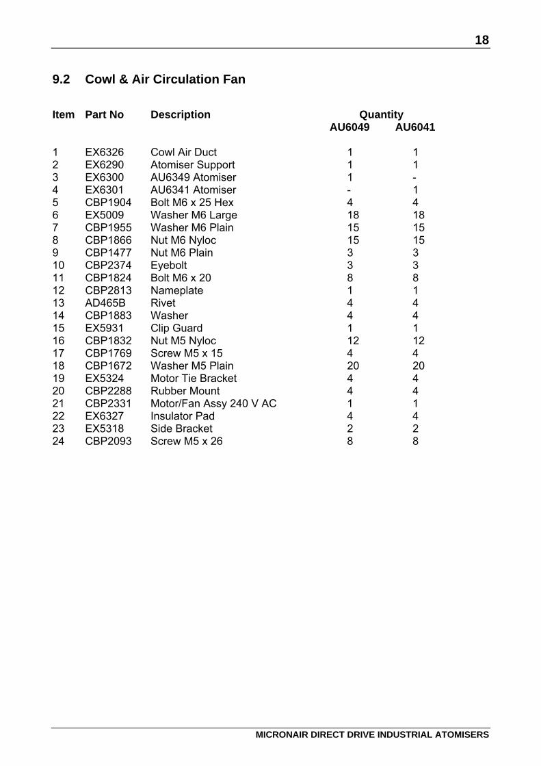
9.2 Cowl & Air Circulation Fan
Item Part No Description Quantity AU6049 AU6041 1 EX6326 Cowl Air Duct 1 1 2 EX6290 Atomiser Support 1 1 3 EX6300 AU6349 Atomiser 1 - 4 EX6301 AU6341 Atomiser - 1 5 CBP1904 Bolt M6 x 25 Hex 4 4 6 EX5009 Washer M6 Large 18 18 7 CBP1955 Washer M6 Plain 15 15 8 CBP1866 Nut M6 Nyloc 15 15 9 CBP1477 Nut M6 Plain 3 3 10 CBP2374 Eyebolt 3 3 11 CBP1824 Bolt M6 x 20 8 8 12 CBP2813 Nameplate 1 1 13 AD465B Rivet 4 4 14 CBP1883 Washer 4 4 15 EX5931 Clip Guard 1 1 16 CBP1832 Nut M5 Nyloc 12 12 17 CBP1769 Screw M5 x 15 4 4 18 CBP1672 Washer M5 Plain 20 20 19 EX5324 Motor Tie Bracket 4 4 20 CBP2288 Rubber Mount 4 4 21 CBP2331 Motor/Fan Assy 240 V AC 1 1 22 EX6327 Insulator Pad 4 4 23 EX5318 Side Bracket 2 2 24 CBP2093 Screw M5 x 26 8 8

19
MICRONAIR DIRECT DRIVE INDUSTRIAL ATOMISERS
Fig. 8 – Cowl with Air Circulation Fan
20
MICRONAIR DIRECT DRIVE INDUSTRIAL ATOMISERS
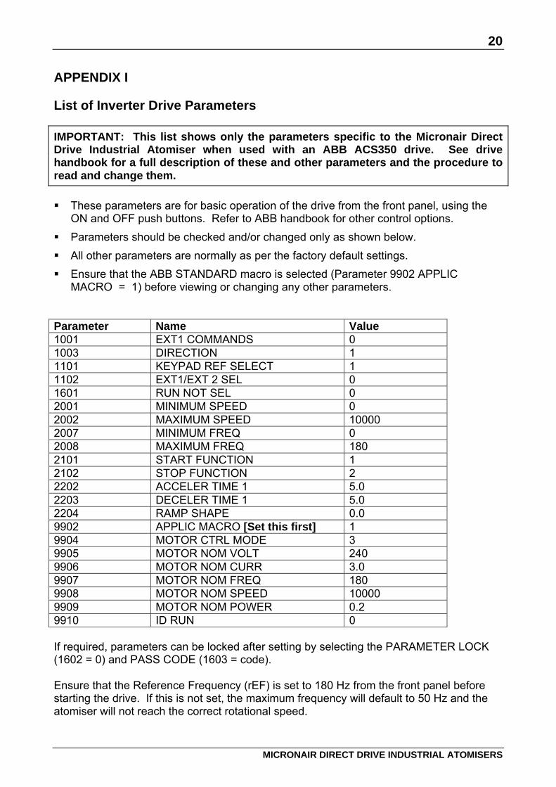
APPENDIX I List of Inverter Drive Parameters IMPORTANT: This list shows only the parameters specific to the Micronair Direct Drive Industrial Atomiser when used with an ABB ACS350 drive. See drive handbook for a full description of these and other parameters and the procedure to read and change them. These parameters are for basic operation of the drive from the front panel, using the
ON and OFF push buttons. Refer to ABB handbook for other control options. Parameters should be checked and/or changed only as shown below. All other parameters are normally as per the factory default settings. Ensure that the ABB STANDARD macro is selected (Parameter 9902 APPLIC
MACRO = 1) before viewing or changing any other parameters. Parameter Name Value 1001 EXT1 COMMANDS 0 1003 DIRECTION 1 1101 KEYPAD REF SELECT 1 1102 EXT1/EXT 2 SEL 0 1601 RUN NOT SEL 0 2001 MINIMUM SPEED 0 2002 MAXIMUM SPEED 10000 2007 MINIMUM FREQ 0 2008 MAXIMUM FREQ 180 2101 START FUNCTION 1 2102 STOP FUNCTION 2 2202 ACCELER TIME 1 5.0 2203 DECELER TIME 1 5.0 2204 RAMP SHAPE 0.0 9902 APPLIC MACRO [Set this first] 1 9904 MOTOR CTRL MODE 3 9905 MOTOR NOM VOLT 240 9906 MOTOR NOM CURR 3.0 9907 MOTOR NOM FREQ 180 9908 MOTOR NOM SPEED 10000 9909 MOTOR NOM POWER 0.2 9910 ID RUN 0 If required, parameters can be locked after setting by selecting the PARAMETER LOCK (1602 = 0) and PASS CODE (1603 = code). Ensure that the Reference Frequency (rEF) is set to 180 Hz from the front panel before starting the drive. If this is not set, the maximum frequency will default to 50 Hz and the atomiser will not reach the correct rotational speed.
21
MICRONAIR DIRECT DRIVE INDUSTRIAL ATOMISERS
Notes
Micronair is the registered trademark of Micron Sprayers Limited, Bromyard, Herefordshire, United Kingdom. Every care has been taken in the design of this equipment and the preparation of this Handbook. However, Micron Sprayers Limited cannot accept responsibility for errors or the consequences thereof. The user must satisfy himself that the equipment is suited to his needs, is performing according to his requirements and that all statutory requirements and codes of practice are complied with.