direct torque control and direct power control of wind turbine
TRANSCRIPT
PRZEGLĄD ELEKTROTECHNICZNY, ISSN 0033-2097, R. 92 NR 10/2016 249
Piotr GAJEWSKI, Krzysztof PIEŃKOWSKI
Wrocław University of Technology, Department of Electrical Machines, Drives and Measurements
doi:10.15199/48.2016.10.56
Direct Torque Control and Direct Power Control of wind turbine system with PMSG
Abstract. The paper presents the control system of variable speed wind turbine with direct-driven PMSG. A back-to-back Voltage Source Converter (VSC) is employed for the power conversion from the PMSG to the AC grid. The control strategy of PMSG and Machine Side Converter (MSC) combines the technique of MPPT, DTC-SVM and the pitch control algorithm. In the control system of the Grid Side Converter (GSC) the application of Direct Power Control (DPC) has been used. The results of digital simulation of the control system have been presented and discussed. Streszczenie. W artykule przedstawiono bezprzekładniowy system turbiny wiatrowej o zmiennej prędkości z generatorem PMSG. System przekształtnikowy jest złożony z przekształtnika maszynowego i przekształtnika sieciowego. Do sterowania generatorem PMSG i przekształtnikiem maszynowym zastosowano algorytm MPPT, DTC-SVM oraz sterowanie kątem pochylenia łopat turbiny. Do sterowania przekształtnikiem sieciowym zastosowano metodę DPC-SVM. Przeprowadzono badania symulacyjne właściwości zastosowanych metod sterowania. (Bezpośrednie sterowanie momentem i mocą w systemie elektrowni wiatrowej z generatorem PMSG). Keywords: wind turbine, PMSG, DTC with MPPT, DPC, simulation studies Słowa kluczowe: turbina wiatrowa, PMSG, DTC z MPPT, DPC, badania symulacyjne
Introduction Wind energy conversion system (WESC) is the one of
fastest growing energy resource among the other renewable generation technologies. The increased trend of wind energy conversion system has a significant impact on the AC grid [1, 2, 3].
Most of the major wind turbines are developed as variable speed wind turbine systems. These types of wind turbines have many advantages: operation at MPPT (Maximum Power Point Tracking) over a wide range of wind speeds, reduced mechanical stresses, greater output power in comparison with the operation at fixed speeds [4, 5]
Nowadays the variable speed wind turbine systems using the direct-driven Permanent Magnet Synchronous Generators (PMSGs) are suitable and promising for application in wind farms [3, 6]. The PMSG can be constructed with a large number of poles and can be operated as low speed direct-driven system without gearbox. This results in reduction of installation and maintenance costs and provides an advantage over the other types of generators.
The electromagnetic construction of the PMSG is more complex than in the case of conventional generators. Currently the direct-driven PMSGs have many advantages over induction generators, including: higher reliability, higher power, higher efficiency, higher torque, no gear and simple control methods [1].
The performance of the wind energy systems can be greatly enhanced with the use of a full-capacity converter system [1, 3]. In these types of power converter systems, the generator is fully decoupled from the grid and can operate in full speed range. In order to convert the electrical energy produced by the PMSG generator the voltage source converters (VSC) should be applied.
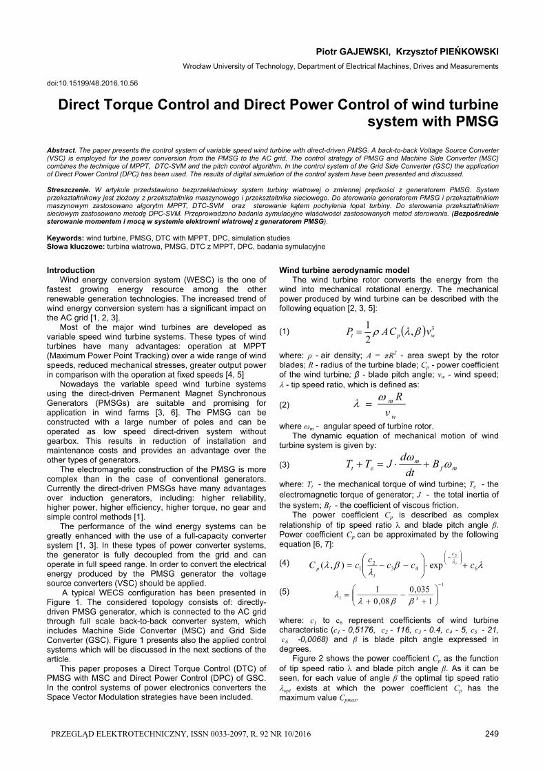
A typical WECS configuration has been presented in Figure 1. The considered topology consists of: directly- driven PMSG generator, which is connected to the AC grid through full scale back-to-back converter system, which includes Machine Side Converter (MSC) and Grid Side Converter (GSC). Figure 1 presents also the applied control systems which will be discussed in the next sections of the article.
This paper proposes a Direct Torque Control (DTC) of PMSG with MSC and Direct Power Control (DPC) of GSC. In the control systems of power electronics converters the Space Vector Modulation strategies have been included.
Wind turbine aerodynamic model The wind turbine rotor converts the energy from the
wind into mechanical rotational energy. The mechanical power produced by wind turbine can be described with the following equation [2, 3, 5]:
(1) 3,2
1wpt vCAP
where: ρ - air density; A = πR2 - area swept by the rotor blades; R - radius of the turbine blade; Cp - power coefficient of the wind turbine; β - blade pitch angle; vw - wind speed; - tip speed ratio, which is defined as:
(2) w
m
v
R
where ωm - angular speed of turbine rotor. The dynamic equation of mechanical motion of wind
turbine system is given by:
(3) mfm
et Bdt
dJTT
where: Tt - the mechanical torque of wind turbine; Te - the electromagnetic torque of generator; J - the total inertia of the system; Bf - the coefficient of viscous friction.
The power coefficient Cp is described as complex relationship of tip speed ratio and blade pitch angle β. Power coefficient Cp can be approximated by the following equation [6, 7]:
(4)
643
21
5
exp),( cccc
cC i
c
ip
(5) 1
3 1
035,0
08,0
1
i
where: c1 to c6 represent coefficients of wind turbine characteristic (c1 - 0,5176, c2 - 116, c3 - 0.4, c4 - 5, c5 - 21, c6 -0,0068) and β is blade pitch angle expressed in degrees. Figure 2 shows the power coefficient Cp as the function of tip speed ratio and blade pitch angle β. As it can be seen, for each value of angle β the optimal tip speed ratio opt exists at which the power coefficient Cp has the maximum value Cpmax.

250 PRZEGLĄD ELEKTROTECHNICZNY, ISSN 0033-2097, R. 92 NR 10/2016
Controller of Machine Side Converter
Grid Side Converter (GSC)
Machine Side Converter (MSC) Grid
Controller of Grid Side Converter
gg RL ,
sabcigabci gabcv
dC
g
PLL
g
dcv
PMSG
*opt
wv
WECS control
wv
m
OTSR – MPPT control
ratedm_
m
dcvMeasured wind speed
ratedtP_
gav
gbv
gcv
Controller of Machine Side Converter
Grid Side Converter (GSC)
Machine Side Converter (MSC) Grid
Controller of Grid Side Converter
gg RL ,
sabcigabci gabcv
dC
g
PLL
g
PMSG
wv
WECS control
wv
m
MPPT and pitch angle control
ratedm_
gp
dcvMeasured wind speed
ratedtP_
gav
gbv
gcv
eT gqs
Fig.1. The scheme of variable speed wind turbine system with direct-driven PMSG generator and back-to-back converter system
0 5 10 15 200
0.1
0.2
0.3
0.4
0.5o0
o5o10
o15
Tip Speed Ratio λ
Pow
er C
oeff
icie
nt ,
Cp
1,8opt
48,0max pC
Fig.2. Power coefficient curves of Cp for diffrent tip speed ratio λ and pitch blade angle β Permanent Magnet Synchronous Generator Model
The considered mathematical model of PMSG is based on the following assumptions [1, 5]: Sinusoidal distribution of stator winding, Electrical and magnetical symmetry, Damping windings are not considered, The magnetic circuits are linear, Saturation effect, eddy-currents and hysteresis losses
are neglected. The model of the PMSG was developed in the
synchronous rotating dq reference frame, where the d-axis is aligned with direction of the permanent magnet flux vector. The mathematical equations of the PMSG in this reference frame can be described as follows [6, 11, 12]:
(6) sqesd
dsdssd dt
diLiRv
(7) sdesq
qsqssq dt
diLiRv
The components of stator flux vector in this reference frame can be given by:
(8) PMsddsd iL
(9) sqqsq iL where: vsd , vsq - dq components of the stator voltage vector; isd, isq - dq components of the stator current vector; Rs - stator phase resistance; ψsd, ψsq - dq components of the stator flux vector; Ld, Lq - direct and quadrature stator inductances; ψPM - flux established by the permanent magnets; np - number of pole pairs of PMSG; ωe, ωm - electrical and mechanical angular speed of the PMSG rotor, defined as:
(10) mpe n
The electromagnetic torque of PMSG generator can be expressed as follows:
(11) sdsqsqsdpe iinT 2
3
The Direct Torque Control of PMSG with Machine Side Converter
The principle of DTC is based on directly selection of appropriate stator voltage vectors according to the differences between reference and actual values of magnitude of stator flux vector and electromagnetic torque. The conventional DTC can be implemented by using the hysteresis flux and torque controllers, which are operated with switching table. This conventional DTC system with hysteresis controllers generates the variable switching frequency caused the electromagnetic torque ripples [3, 8]. Moreover the high sampling frequency is needed for digital implementation of hysteresis comparators.
The alternative for control with switching table is the implementation of improved DTC with Space Vector Modulation (DTC-SVM). The DTC-SVM ensures the lower harmonics stator current and allows to reduce the electromagnetic torque ripples. The other advantage of using SVM modulation is the possibility of maintaining the constant switching frequency [2, 4].
Figure 3 shows the block scheme of DTC-SVM system for control of PMSG with MSC. The control scheme consists of three control loops.
The outer control loop with PI controller regulates the generator speed to follow the optimum speed ωopt of wind turbine rotation at which the maximum of turbine power is obtained. In order to achieve the operation at conversion of maximum mechanical power from wind turbine the special algorithm of Maximum Power Point Tracking (MPPT) has been applied in the control system. Additionally at wind speeds greater than rated wind speeds the respectively limitations of the wind turbine mechanical power is required. This task has been realized by adopting the pitch angle control of the blades of wind turbine. The applied algorithms of MPPT and pitch control have been described below. In the control scheme presented in Figure 3 these algorithms have been combined in the common control block.
The two inner control loops with PI controllers regulate the magnitude of stator flux vector and the electromagnetic torque of the PMSG. In the PI controller of the stator flux vector the reference and the real estimated value of the magnitude of stator flux vector are compared. The output of this controller determines the reference component vsx
*
of the stator voltage vector in the reference frame xy oriented with stator flux vector. In the PI controller of the electromagnetic torque the reference and the real estimated

PRZEGLĄD ELEKTROTECHNICZNY, ISSN 0033-2097, R. 92 NR 10/2016 251
value of the electromagnetic torque of PMSG are compared. The output of this controller determines the reference component vsy
*
of the stator voltage vector in the xy system. The both output signals from these controllers are transformed to the stationary αβ system and determine the components vsα
* and vsβ
* of the reference stator voltage vector for SVM of MSC.
PMSG
ratedmm _,
dC
m
e
αβ xy
SVM
m
tPMachine Side
Converter (MSC)
sai sbi sci
MPPT and pitch angle control
*opt
encoder
ratedtP_
wv
wv
Measured wind speed
dcv
tPEstimator
of Pt
PIPI
PI
Torque and Stator Flux Estimator
*
eT
eT*
s
s
*sxv *
syv
*sv *
sv
aS bS cS
s
Fig.3. Control diagram of Direct Torque Control with Space Vector Modulation
To obtain the estimation of the magnitude of stator flux
vector and the electromagnetic torque the several techniques have been presented in literature [4, 8, 11]. Most of these techniques are based either on the voltage model method or on the current model method [8, 11, 16]. In the method of voltage model the magnitude of stator flux vector can be estimated by directly measuring of the stator phase currents and voltages. The measurement of stator phase voltages can be replaced by measuring DC bus voltage and by using the information of the MSC switching states. In the method of current model the magnitude of stator flux vector is estimated on the base of directly measuring of the stator phase currents and the measuring of the actual electrical angle position of the rotor. The application of current model allows to eliminate the stator voltage sensors and the influence of stator phase resistance variations, which usually worsen the performance and robustness of estimation block.
The magnitude of the stator flux vector can be calculated as:
(12) 2222PMsddsqqs iLiL
ss
where: the stator flux vector components ψsα, ψsβ are obtained from the transformation of the ψsd, ψsq components. The current model considered for estimation of the magnitude of stator flux vector ψs and the electromagnetic torque Te is shown in Figure 4 [10, 11].
abc
αβ
si
si
sai
sbi
sci
αβ
dq Lq
Ld
αβ
dqCartesian To Polar
e
sd
sq
s
s
s
PM
s
sdi
sqi
eTEq. (11)
Fig.4. Current model for estimation of the magnitude of stator flux vector and the electromagnetic torque The MPPT algorithm and pitch angle controller
The pitch angle controller is one of the used control techniques to regulate aerodynamic power of wind turbine. The output wind turbine mechanical power can be transformed as [9]:
(13) 353
32 ),(5,0),(5,0 m
ppwt R
CCvRP
The maximum value of wind turbine power Ptmax is specified at maximum value of Cpmax and optimal value of the tip speed ratio opt. By replacing by opt and Cp (, β) = Cp (opt, β,) the maximum power of wind turbine can be formulated as:
(14)
3max moptMPPTt KPP
where: Kopt - coefficient of wind turbine.
(15) 5
3
),(
2
1R
CK
opt
optpopt
According to power characteristic PMPPT of wind turbine and equation (14) the reference speed of generator can be developed as [5, 7]:
(16) 3 / optMPPToptref KP
The pitch angle controller is used to limit the aerodynamic power produced by the wind turbine by adjusting the pitch angle of the wind turbine blades. The pitch angle controller is active only when wind speeds are above the rated wind speed.
The block diagram of the typical pitch angle controller has been presented in Figure 6 [7].
ratedm_
m
ratedtP_
tP
sT c1
1
Fig.6. Wind turbine pitch angle controller
In the control system of pitch controller the upper control loop with PI controller is the basic part of the system and the lower part with proportional gain Kw is used as correction part. In the basic controller, the reference rated mechanical turbine power is compared with real value of mechanical turbine power. PI controller sets the output value of the pitch angle β. To prevent the possibility of mechanical damage, when the turbine rotor speeds are above the rated wind speed, the blade pitch angle is changed in order to reduce tip speed ratio and power coefficient Cp, respectively.
The Direct Power Control of Grid Side Converter
The main task of the grid side converter (GSC) is to maintain the voltage in the DC link and control the assumed reactive power delivered to the AC grid. The equations of grid side electrical circuits formulated in the synchronous rotating dq reference frame with d-axis oriented with the grid voltage vector have the following form [12, 13, 14]:
(17) gcdgqgggdggdggd viLi
dt
dLiRv
(18) gcqgdgggqggqggq viLi
dt
dLiRv
where: vgd, vgq - the dq components of the grid voltage vector; igd, igq - the dq components of the grid current vector; vgcd, vgcq - the dq components of the voltage vector of grid side converter; Lg, Rg - inductance and resistance of the grid filter; ωg - angular frequency of the grid voltage.
In the conventional Direct Power Control (DPC) the hysteresis controllers and switching table have been used. This control strategy is characterized by varied switching frequency of control signals.

252 PRZEGLĄD ELEKTROTECHNICZNY, ISSN 0033-2097, R. 92 NR 10/2016
In the control system of GSC considered in this paper the improved DPC-SVM method has been applied. The block scheme of GSC control system is presented in Fig. 7. This method has simple structure, low number of co-ordinates transformations and good dynamic properties [14]. The temporary angle positions θg of the grid voltage vec-or are obtained from the Phase Locked Loop (PLL) block. The applied PLL system is a feedback system with PI-regulator tracking the phase angle of grid voltage vector [15].
The control algorithms of DPC-SVM are based on the active and reactive power estimator as [14, 15]:
(19)
ggggg ivivp 2
3
(20)
ggggg ivivq 2
3
where: vgα, vgβ - components of the grid voltage vector,
igα, igβ, - components of the grid current vector in the stationary αβ frame.
dcv
PI
Active and Reactive Power calculationEq. (19, 20)
PI
PI Grid Side Converter
dq
g
αβ
*gcv
*gcv
abc
αβ
gavgbvgcv
abc
αβ
SVM
dcv
dC
PLL
Grid
gg RL ,
abc
gq
gp
*
gp
*
gq
*
dcv
gv
gv
gi
gi
gabcv
gabci
aS
bS
cS
*
gdi
Fig.7. Control diagram of Direct Power Control of GSC with Space Vector Modulation
The control strategy of DPC-SVM for grid side converter uses three control loops with PI controllers. The outer control loop regulates DC link voltage of GSC converter. Two inner control loops regulate the active and reactive power of AC grid. The estimated values of active and reactive grid power are compared with the reference values.
In the typical control systems the reactive grid power reference is set to zero in order to perform the operation at unity power factor. The active grid power reference is calculated on the base of multiplication of the measured DC voltage of the converter and the reference value of igd* obtained from the outer control loop. The output signals from PI controllers determine the reference voltages vgcα
*
and vgcβ* for SVM of GSC.
Simulation Results
The simulation model of wind energy conversion system with the considered control systems has been implemented in MATLAB/Simulink. The aim of simulation was the investigation of properties of control systems. For this reason the digital simulation studies were made for the system with small power. The used wind turbine parameters are as follows: rated power Pt=20kW; rotor radius R=4,4m; air density ρ=1,225 kg/m3 and 3-phase PMSG parameters: rated power Pg=20kW; stator resistance Rs=0,1764 Ω; stator dq-axis inductance Ld, Lq=4,48mH; rated speed nn=211rpm; rated stator phase current Isn=35,1 A.
The obtained simulation results of considered wind energy conversion system are presented in Figures 8-16.
The considered control system of WECS have been tested for the assumed wind speed variation during the period of the 10s presented in Figure 8. The rated wind speed has been adopted as equal to 11m/s.
1 2 3 4 5 6 7 8 9 105
10
15
v w [
m/s
]
vwr
vw
t [s]
Fig.8. Waveforms of rated vwr and real wind speed vw
Figure 9 shows the waveforms of optimal ωopt and measured angular speed ωm of PMSG obtained from simulation of control system. It can be seen, that the generator speed ωm is accurately adjusted to the waveforms of optimal speed ωopt, which is obtained from MPPT algorithms.
1 2 3 4 5 6 7 8 9 1010
15
20
25
30
ωm
, ω
opt
[rad
/s]
t [s]
ωopt
ωm
Fig.9. Waveforms of the reference speed ωopt and the actual speed ωm of PMSG
The obtained waveforms of tip speed ratio, blade pitch angle and power coefficient at various wind speeds have been presented in Figures 10-11. From this Figures the proper operation of the blade pitch angle controller can be stated and confirmed.
1 2 3 4 5 6 7 8 9 100
5
10
15
TS
R λ
, β
t [s]
λopt= 8,1
β
Fig.10. Waveforms of tip speed ratio and blade pitch angle β
1 2 3 4 5 6 7 8 9 10
0.2
0.4
0.6
0.8
Cp
t [s]
Cpmax=0,48
Fig.11. Waveform of power coefficient of wind turbine Cp
Figure 12 presents the responses of electromagnetic torque Te of PMSG and mechanical torque Tt of wind turbine during the considered variation of wind speed. The considered control system allows fast responses of the electromagnetic torque Te of PMSG during temporary time variations of the wind speed.
1 2 3 4 5 6 7 8 9 10
-1000
-500
0
500
1000
1500
Te
,Tt [N
m]
t [s]
Te
Tt
Fig.12. Waveforms of electromagnetic torque Te of PMSG and mechanical torque Tt of wind turbine
The Figure 13a presents the waveform of the magnitude ψs of stator flux vector and Figure 13b presents the trajectory of stator flux vector. The Figure 14 presents the waveform of the voltage vdc in DC link. The instantaneous

PRZEGLĄD ELEKTROTECHNICZNY, ISSN 0033-2097, R. 92 NR 10/2016 253
values of voltage vdc are quite constant at variations of wind speeds.
s
-1 -0.5 0 0.5 1
-1
-0.5
0
0.5
1
2 4 6 8 100
0.2
0.4
0.6
0.8
1
t [s]s
s
Fig.13. a) Waveform of magnitude of stator flux vector, b) Trajectory of stator flux vector
1 2 3 4 5 6 7 8 9 10650
700
750
v dc [
V]
t [s]
vdc=690V
Fig.14. Waveform of DC link voltage vdc of GSC
Figure 15 shows the instantaneous active and reactive power pg and qg delivered to the AC grid. From Figure 15, it can be noticed, that the instantaneous reactive power qg is constantly maintaining at zero values. It means that only the active power generated by WECS is fully delivered to the AC grid, while the reactive power is equal to zero.
1 2 3 4 5 6 7 8 9 10
0
1
2
3x 10
4
p g ,
q g [
kW
]
t [s]
qg
pg
Fig.15. Waveforms of active and reactive grid power pg, qg
Figure 16 presents the waveforms of the grid phase voltage and grid phase current. It can be noticed, that the waveforms of grid current and voltage are in antiphase directly, according to return of active power to grid.
6.1 6.12 6.14 6.16 6.18 6.2 6.22 6.24 6.26 6.28 6.3-500
0
500
6.1 6.12 6.14 6.16 6.18 6.2 6.22 6.24 6.26 6.28 6.3
-50050
v ga [
V]
vga
iga
i ga
[A]
t [s]s
Fig.16. Waveforms of grid phase voltage vga and current iga
Conclusions
In this paper the dynamic modeling and control structures of wind turbine system with variable speed direct-driven PMSG have been considered. The control algorithm of PMSG with MSC is based on Direct Torque Control with cooperation of MPPT algorithm. For control of GSC the Direct Power Control method has been applied.
Direct Torque Control with MPPT allows to convert the maximum power of wind turbine in order to obtain the optimal operation of WECS. Additionally the pitch control scheme is proposed to achieve limitation of maximum turbine power at great wind speeds and to prevent mechanical damage of wind turbine. DPC control of GSC enables to keep the DC link voltage to reference value and to adjust the reactive power of the system. The presented simulation results confirmed that the considered wind turbine with direct-driven PMSG generator system has good performances and good control properties.
Authors: Piotr Gajewski, M.Sc., Krzysztof Pieńkowski, D.Sc., Ph.D., Wrocław University of Technology, Department of Electrical Machines, Drives and Measurements, ul. Wybrzeże Wyspiańskiego 27, 50-370 Wrocław [email protected], [email protected]
REFERENCES
[1] Wu B ., Youngquan ., Nav id Z., Sami r L . , Power Conversion and Control of Wind Energy, John Wiley & Sons, INP., Publication (2011).
[2] Magesh M., Sundareswaran R ., PMSG Based Wind Energy Conversion with Space Vector Modulation, International Journal of Energy and Power Engineering. Vol. 4, No. 3, (2015), 146-152.
[3] Hasnaou i B .K .O., A l l aqu i M ., Be lhad j J ., PMSG Gear-Less Wind Turbine Equipped with an Active and Reactive Power Supervisory, International Journal of Renewable Energy Research., Vol. 4, No. 2, (2014), 435-444.
[4] I nnoue Y., Mor imoto S ., Sanada M., Control method for direct torque controlled PMSG in wind power generation system, IEEE International in Electric Machines and Drives Conference, IEMDC '09, (2009), 1231-1238.
[5] Wang Y., Ha i R ., Power Control of Permanent Magnet Synchronous Generator Direct Driven by Wind Turbine, International Journal of Signal Processing System, Vol. 1, No. 2, (2013), 244-249.
[6] E r rami Y., Ouassa id M., Cherkaou i M ., Maarou f i M ., Variable Structure Sliding Mode Control And Direct Torque Control of Wind Power Generation System Based on The PM Synchronous Generator, Journal of Electrical Engineering, Vol. 66, No. 3, (2015), 121-131.
[7] E r rami Y., Maarou f i M ., Ouassa id M., Modeling and control strategy of PMSG based variable speed wind energy conversion system, International Conference on Multimedia Computing and Systems (ICMCS), (2011), 1-6.
[8] Sekhara R ., Space Vector Modulated Direct Torque Control of IPMSM Drive, International Advanced Research Journal in Science, Engineering and Technology, Vol 2. Issue 8, (2015), 45-49.
[9] Muyeen S .M., Takahash i R ., Mura ta T ., Tamura J ., A Variable Speed Wind Turbine Control Strategy to Meet Wind Farm Grid Code Requirements, IEEE Transactions on Power Systems, vol.25, no.1, (2010), 331-340.
[10] Ch ikh K ., Saad A ., Khafa l l ah M., Yous f i D ., A novel drive implementation for PMSM by using direct torque control with space vector modulation, Canadian Journal on Electrical and Electronics Engineering, Vol. 2, No. 8, (2011), 400-408.
[11] Swie rczyńsk i D ., Direct Torque Control with Space Vector Modulation (DTC-SVM) of inverter-fed Permanent Magnet Synchronous Motor Drive, Ph.D Thesis, Warsaw University of Technology, (2005).
[12] Ga jewsk i P ., P ieńkowsk i K ., Control of a Variable Speed Wind Turbine System With PMSG Generator, Zeszyty Problemowe, nr 107, (2015), 75-90.
[13] Ga jewsk i P ., P ieńkowsk i K ., Analysis of a wind Energy converter system with PMSG generator, Czasopismo Techniczne. Elektrotechnika = Technical Transaction. Electrical Engineering. Nr 2E, (2015), 219-228.
[14] Ma l i nowsk i M ., Jas ińsk i M ., Kaźmierkowsk i M .P., Simple Direct Power Control of Three-Phase PWM Rectifier Using Space-Vector modulation (DPC-SVM), IEEE Transaction on Industrial Electronics, Vol. 51, No. 2, (2004), 447-454.
[15] M i l cza rek A ., Ma l inowsk i M ., Monitoring and control algorithms applied to small wind turbine with grid-connected/stand-alone mode of operation, Przegląd Elektrotechniczny, 88, (2012), nr 12a, 18-22.
[16] Bouwer P ., Kamer M., Sensorless small-scale variable speed wind energy conversion system incorporating DTC-SVM of direct-driven PMSG with RLC filter, Energy Conversion Congress and Exposition (ECCE), (2012), 3756-3763.