direct wysiwyg painting and texturing on 3d...
TRANSCRIPT
~ Computer Graphics, Volume 24, Number 4, August 1990
Direct WYSIWYG Painting and Texturing on 3D Shapes
Pat Hanrahan* and Paul Haeberlit *Pr ince ton Univers i ty
tS i l i con G r a p h i c s C o m p u t e r Sys tems
Abstract
This paper describes a 3D object-space paint program. This pro- gram allows the user to directly manipulate the parameters used to shade the surface of the 3D shape by applying pigment to its sur- face. The pigment has all the properties normally associated with material shading models. This includes, but is not limited to, the diffuse color, the specular color, and the surface roughness. The pigment also can have thickness, which is modeled by simultane- ously ereating a bump map attached to the shape. The output of the paint program is a 3D model with associated texture maps. This information can be used with any rendering program with texture mapping capabilities. Almost all traditional techniques of 2D computer image painting have analogues in 3D object paint- ing, but there are also many new techniques unique to 3D. One example is the use of solid textures to pattern the surface.
CR Categories: 1.3.5 [Computer Graphics] Three-Dimensional Graphics and Realism - Color, shading, shadowing and texture; Visible line/surface algorithms. 1.3.6 [Computer Graphics] Methodology - Interaction Techniques
Additional Keywords and Phrases: Painting, direct manipula- tion, user-interface
Permission to copy without fee all or part of this material is granted provided that the copies are not made or distributed for direct commercial advantage, the ACM copyright notice and the title of the publication and its date appear, and notice is given that copying is by permission of the Association for Computing Machinery. To copy otherwise, or to republish, requires a fee and/or specific permission.
i . In troduct ion
In recent years the technology of 3D computer graphics is finding application in a large number of different disciplines. In the near future, it is likely that the typical personal computer or workstation will be fast enough to produce 3D models, anima- tions, and high quality computer generated imagery just as easily as the typical personal computer of today produces 2D paintings, illustrations, and documents. The key to the widespread use of 3D computer graphics, however, is not just dependent on advances in hardware, but requires similar advances in interactive techniques that make 3D concepts easy to use and accessible to large numbers of people.
There is no reason to think this is an impossible task. Almost all the design principles that have been successfully applied to designing current user interfaces are likely to apply to 3D applications as well. One such principle is to use common metaphors. Users can then rely on their everyday experience to infer how a program works by analogy with how everyday things work[I,22]. This principle is easy to apply in 3D computer graphics because the 3D world provides so many concrete meta- phors. Another general principle in designing user interfaces is direct manipulation[27]. A pointing device such as a mouse can be used to move, drag, or manipulate graphics representations on the screen. The act of moving the mouse is directly associated with some action to be performed, and feedback is given immedi- ately to reinforce the action. Ideally, the results of the interactive action should be a faithful reproduction of the final product, or WYSIWYG (What You See Is What You Get).
Unfortunately, most applications involving 3D computer graphics are still indirect and not WYSIWYG. The most progress has been in positioning and creating geometric models[3,21]. One example is the virtual sphere where the user rotates an object by manipulating a hypothetical crystal ball containing the object[9]. Another example is to fix a 3D plane and use the same direct manipulation techniques used by 2D illustration programs to create and modify geometry on the plane. This 2D geometry can be converted to 3D models using sweep operations. More recently, Williams has described how a ordinary paint program can be used to sculpt height fields[33]. However, the models needed for computer generated imagery involve not only geometric attributes, but also optical attributes that define the pro- perties of materials and light sources. One technique for interac- tively modifying the optical properties of a single surface illuminated by distant lights is to display an image of quantized surface norrnals (sometimes referred to as an orientation coded image) using a colormap whose entries have been set to the
© 1990 ACM -0-89791-344-2/90/008/0215 $00.75 215
@ SIGGRAPH '90, Dallas, August 6-10, 1990 I iiiii i
calculated shades[2, 7, 15, 28]. This type of table is often referred to as a reflectance map. Since the reflectance map is small it can be recomputed quickly so the properties of the lights or of a single surface can be adjusted in real-time. Warn describes a program for interactively manipulating the position and properties of spotlights[31]. Some commercial modelers contain material edi- tors that allow the user to adjust the various coefficients that go into the standard shading models by using sliders. These editors normally shade a single simple shape such as a sphere and not the objects being built by the modeler.
The visual appearance of materials is strongly influenced by their spatial textures and patterns, not only their local reflectance properties. The above methods for directly manipulat- ing materials and lights only work with surfaces made of materials with uniform properties. In computer graphics the most expedient way to model local variations in material properties involves using texture maps[16]. Texture maps are images mapped onto a surface. The value of the texture map at a point on the surface is used to control parameters in the local shading formula. Texture maps can be used to modulate surface color[8] and tran- sparency[13], ambient, diffuse and specular coefficients, and the roughness or shininess (specular exponent) of the surface. Tex- ture maps can also be used to select between different types of materials; this allows a simple shape to contain inlays or be con- structed from composite materials[10]. Finally, texture maps can be used to modulate small-scale geometric properties. Normals can be perturbed using bump maps[6], positions can be displaced using a height field or displacement map[10], and a preferred tangential direction (for use with anisotropic shading models) can be defined using tangent bundle mapping[17,20]. Because of their versatility, texture maps are a key component of a high qual- ity rendering system.
Texture maps are typically created by scanning in existing artwork, painting them with a 2D paint program, or synthesizing them from procedural image models. However, because the crea- tion of the texture and the mapping of it to the surface are separated, setting up a model involving texture mapping is an indirect process, This makes using texture maps to modulate material properties tedious and error prone. First, it is difficult to place the texture map on the surface in the desired position and orientation. This is made more complicated if several surfaces share the same texture map, because it is important that no seams be visible at their boundaries. Second, the texture map is often indexed by the surface parameters, so this requires the user to know about the mathematics of the surface parameterization when creating the texture map. Another problem is caused because when a curved surface is uniformly subdivided in parameter space, the surface area of each piece can vary greatly. This causes the texture map to be locally compressed or expanded in different parts of the surface, and results in undesirable distortions which must be undone when creating the texture map.
This paper describes an interactive paint program that allows the user to directly paint with different types of pigments and materials onto 3D shapes. The user controls the position of a brush using a tablet; the brush contains paint that is applied to the shape being painted on. Rather than creating a final 2D image like most paint programs, this paint program creates an object description that describes the composite material properties every- where on the surface of the object. The material properties are stored as a set of associated texture maps. An image is created of this object using conventional rendering techniques (optimized for this application) as the user paints. These material properties interact with the illumination environment to create the appear- ance of the object. Almost all the conventional computer painting modes can be used with this program. Examples include
216
mm
eml
Q.S2
I I Im
I
LJl~,~t
I
£1 0 ,Se | b i n 0*lm I I I I l | r l t l IOI,I .~I i Iv 0 .~S
I
°
!
" I [ !
[
_J o.a,? tM 0.49
I
I I
m l
. I
O - S S | h l n O * W I l l l t J r l l l l Lllllbt I n t | a m i t l / O.ll?
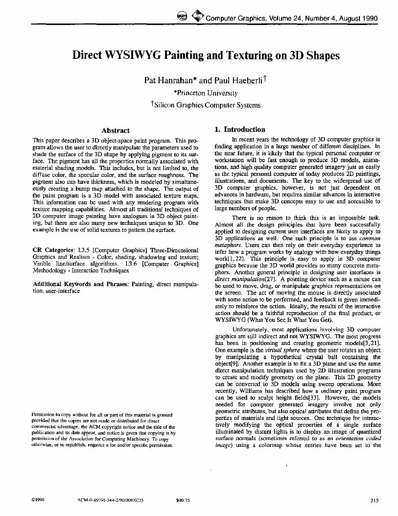
Figure 1. The material editor medit. Above, a metallic bronze; below, a green plastic.
airbrushing or alpha blending, smearing, patterning, table paint- ing, etc[29,30]. However, some computer painting effects, such as z-paint[30,32], are just simulations of things that can be directly done in 3D, in this case using bump mapping. In fact, conventional 2D painting can be interpreted as a special case of this program, where a painting is made by laying down pigment on a 3D fiat rectangular polygonal canvas. Other painting effects, similar to how a pottery maker or sculptor might work rather than a traditional painter, are also possible with this program. Once the model has been painted the geometry and the texture maps can be saved and used with traditional batch rendering programs.
2. Material and Geometric Representations The pigments used as paint have the same properties as
materials used in shading calculations. The properties are defined by the following shading formula:
C = (Ka*Ca)*La + (Kd*Cd)*Ld(P,N) + (IKs*Cs)*Ls(P,N,r)
K a - ambient coef~cient C a - ambient color L a - ambient l ight color
K d - diffuse coe3~cient C d - diffuse color Lcl - diffuse light color
r - roughness K s - specular coefficient C s - specular color L s - specular light color
~ Computer Graphics, Volume 24, Number 4, August 1990
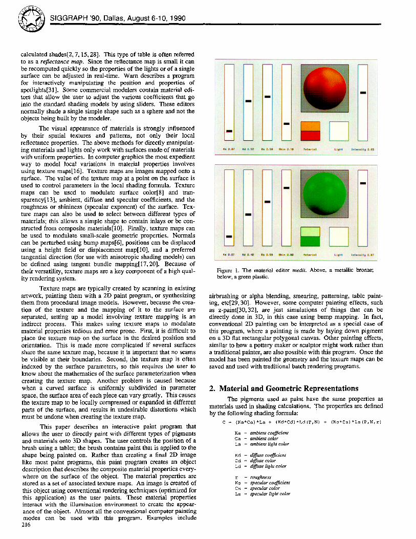
Figure 2. A painted pot and its associated texture maps: (upper left) the diffuse color, (upper right) the specular color, (lower left) the roughness, (lower right) the displacement.
The local properties of a material are modeled as an ambient color (Ka*Ca), a diffuse color (Kd*Cd), ahd a specular color (Ks*Cs). For simplicity the ambient coefficient and color are set equal to the diffuse values. The roughness or shininess is also a material property. Rough materials ( r = l ) have fuzzy highlights while smooth or shiny materials ( r=0 ) have sharp highlights. The vari- ous light colors (La, Ld, and Ls) are given by sums over all the lights illuminating the object times the bidirectional reflection function for that type of light transport. The diffuse transport is given by Lambert 's law and is a function of the surface position and normal; the specular transport is given by a simplified version of the Torrance-Sparrow model described by Blirm[5] and is a function of the position, normal and roughness. The choice of this shading model was motivated by what is commonly available in real-time rendering systems, but other shading models could also be used.
Material pigments are created using an interactive pigment editor shown in Figure 1. Sliders control the relative contributions of ambient, diffuse and specular light. The diffuse and specular colors can be set by picking colors on the screen from color edi- tors and palettes running as separate processes. The properties of light sources can also be controlled by this editor. Lights are posi- tioned by interactively dragging their highlights on a sphere, and calculating the position of the light that would cause a highlight at the new location.
The paint program internally stores geometric objects as rectangular meshes. Meshes are a common surface representation in computer graphics and can be created in a variety of ways: (i) from mathematically defined parametric surfaces such as spheres or tori, (ii) from procedurally defined models such as surfaces of revolution formed from arbitrary curves, or (iii) from a 3D input device such as a Cyberware scanner or Polhemus digitizer. A mesh defines a discrete parametric surface. The independent parameters of the surface are the 2D integer indices of the mesh, and the dependent data is a vertex containing the position, normal, diffuse and specular color, the roughness, and the bump height.
The mesh data structure is organized so that only the vertex data that is needed is allocated, and so that it is easy to add additional fields to experiment with new material properties. The optional appearance attributes are organized as 2D arrays, and are really
just texture maps embedded in the mesh structure. It is easy to extract them from the mesh data structure and store them as image files or directly as texture maps depending on the requirements of the final rendering system. The size of the mesh is related to the size of the texture maps created and is under user control. The mesh structure also stores whether the mesh wraps around in either the u or v direction, or both, and this information is used when painting. Figure 2 shows a shaded image of a pot and the set of four associated texture maps.
The material and geometric data structures were chosen so that the object could be drawn quickly. Since most existing graphics hardware does not support the use of texture maps, we choose to draw the mesh as many small 4-sided micropolygons.
bgnpolygon ( ) ; material (Cd [u] Iv] , Cs [u] [v] , r [u] [v] ) ; normal (N[u] [v] ) ; vertex (P [u] Iv]); vertex (P [u+l ] Iv] ) ; vertex (P [u+l ] [v+l ] ) ; vertex (P [u] [v+l] ) ;
endpolygon () ;
The material procedure outputs the parameters for the current material, and the remainder of the procedures output the geometric information. The graphics system handles the transfor- marion and shading of each micropolygon. Hidden surfaces are removed using a z-buffer.
The workstation we are using, a Silicon Graphics 4D220 GTX, which is typical of a high-performance 3D workstation, is capable of drawing approximately 100,000 shaded quadrilaterals per second. (Although this number depends on the size of the polygons, the number of light sources, and is particularly sensitive to how often the surface roughness changes.) This means that a mesh with a 512 by 512 texture map can be drawn in about 2 1/2 seconds. Since this is not fast enough to redraw the entire object in real-time, it is useful to optimize drawing for two cases: when moving the object or camera, and when painting on the object. When the position of the object changes, the mesh is subsampled to a resolution that can be drawn in real-time, and then redrawn in its entirety when the movement ends. The next frame is always drawn into the back-buffer while the current frame is being displayed in the front-buffer. Double-buffeting insures that the
217
@ SIGGRAPH '90, Dallas, August 6-10, 1990
the normal. This is a reasonable approximation to what might happen if a real 3D brush was being used to paint on a solid object, since the brush bends to conform to the sur- face.
Since parameter space brushes can b e implemented much like 2D brushes in a 2D paint program, that method is used at the lowest levels to implement the actual painting into texture maps. The other two methods could be implemented by first distorting the brush pattern to form a parameter space brush, and then using the distorted brush to perform the painting. In general, the distortion of the brush is a complicated non-linear mapping to parameter- space and cannot be easily approximated. Fortunately, the map- ping from screen-space to parameter-space is stored in the object id buffer. At each xy screen location is the uv parameter that is visible at that location and this information can be used to recon- struct the functions u(x,y) and v(x,y). This reconstruction of the distortion is valid as long as all mieropolygons contain at least one sample, or, are magnified and not minified. Unfortunately, this technique does not work for tangent-space brushes. Another approach to simulating screen-space brushes is to simulate spray painting by randomly picking points within the brush and apply- ing dabs of paint at these locations. This technique has the nice effect of varying the density of the applied paint with the cosine of the angle between the normal and the viewing direction. Inclined surfaces receive less paint per unit area than surfaces normal to the direction of view.
Resampling brushes allows the paint program to undo any distortions due to the surface parameterization, and makes the sys- tem feel more natural. Unfortunately, resampling brushes is expensive and involves making simplifying assumptions; also, since these brush distortions are done in the innermost loops, they can slow the system down.
Paint is usually applied to a surface using strokes. A stroke begins when the tablet stylus or mouse button is pressed and con- tinues until the pressure is released. Most paint programs allow different types of strokes. For example, a rubberstamp only sam- ples the initial position, a rubberband stroke allows for perfectly straight lines, and an inteipolated strokes fills in intermediate brush positions between sampled cursor positions. All these methods can be used with this paint program. However, there are some subtleties in 3D painting that don ' t come up in 2D painting. One issue is when to terminate a stroke. A stroke should always end when there is no object underneath the brush. A stroke should normally end whenever a silhouette is crossed, since that would cause the brush to leave the surface momentarily as it jumps to its new position. It is reasonable, however, to think that silhouettes should be handled differently for screen-space vs. object-space brushes, since a screen-space brush tends to behave like spray can. It is also unclear whether paint should be applied to portions of the surface which are back-facing even though the center of the brush is on a front-facing surface. Another issue unique to 3D is the fact that there may be multiple objects (this would be like having multiple canvases in 2D). A parameter- space brush naturally paints on only one object; a tangent-space or screen-space brush, however, might feel more natural if it were allowed to paint on multiple objects if positioned near a point of intersection or contact between objects. A similar issue comes up when surface patches are pieced together, or joined to themselves. Connectivity information is important, otherwise seams might be visible when painting across a boundary. Ideally these details about the structure of the model should not be known by the user. Surfaces also have two sides, so it is reasonable to require a com- plete set of materials properties for the inside and outside surface.
218
4. Paint Modes and the Paint Equation The mathematics of painting is controlled by the paint
equation[26, 30]. surface = blend( paint op surface, surface, brush )
This equation governs how the brush controls the application of paint to the surface. The brush shape is represented by a matte image; the brush is present where the matte image is 1, and not present where the values are 0. The matte is continuous so that it can represent the partial coverage of the brush over a matte sam- ple[32]. The function blend, also sometimes referred to as lerp, linearly interpolates the first two arguments under the control of the third argument.
blend(cO,cl,a) = (l-a)*cO + a*cl = cO + a*(cl-cO)
This blend in the paint equation combines the original values on the surface with the new computed values resulting from the interaction of the paint with the surface.
There are many different possible paint operators. Those based on compositing are described in Salesin and Barzel[26]. The most common of which are copy and over. Other possibilities include max to implement z-paint[30,32], filtering Or blurring under the brush to simulate smearing or mixing, and sliding the surface values in a certain direction to simulate another form of smearir~g. All these painting modes can, in principle, be used when painting in 3D.
Normally the paint on the brush is a constant material, but it is possible to allow the paint to vary as a function of position so that the paint has texture or is patterned. We will refer to this as pattern paint. The value of the paint applied at a given position is a function of a constant pigment and the pattern.
paint = pigment in pattern(P)
Ordinary painting can be considered a special case of pattern paint, if we use a pattern that is constant. The pattern function can be generated procedurally (see, for example, Lewis)[18], or from stored 1D tables, 2D images, or 3D voxel arrays. The pattern is combined with the pigment using the in compositing opera- tor[25] which says the pigment is present only where the pattern matte alpha values are non-zero. Since patterns don ' t always con- tain a matte, we provide two built-in methods for automatically generating mattes. Self-matting sets the matte to the value of the pattern, and opaque-matting sets the matte to 1.
In most 2D paint programs, patterns are indexed by the coordinates of the canvas. In our 3D paint program, there is a much richer set of pattern coordinate transformations. First, there is a question as to what set of variables to use to index the pattern. These can be either (i) the surface parameters or texture coordi- nates (u,v), (ii) the screen or raster coordinates (x,y), or (iii) the position of points on the surface P. The default method used is texture coordinates, since this seems to be most like ordinary pat- tern paint. Using raster coordinates is useful if the brush is in screen space and the pattern is designed to simulate a frisket. Finally, using the surface position allows solid textures[19, 23, 24] to be used as patterns and leads to many new painting styles. When using solid textures as patterns it is also useful to transform points before indexing the solid texture. The same solid texture can then be overlaid multiple times with different orientations and phases. This is done by positioning the object with respect to a reference cube defining the texture coordinate system (by default this cube is aligned with the viewing pyramid) and issuing a com- mand which sets transformation to texture coordinates.
An operator exists to apply a wash to the geometric object. This is equivalent to painting everywhere on the object and is used to set the initial material properties and to apply patterns and
~ Computer Graphics, Volume 24, Number 4, August 1990
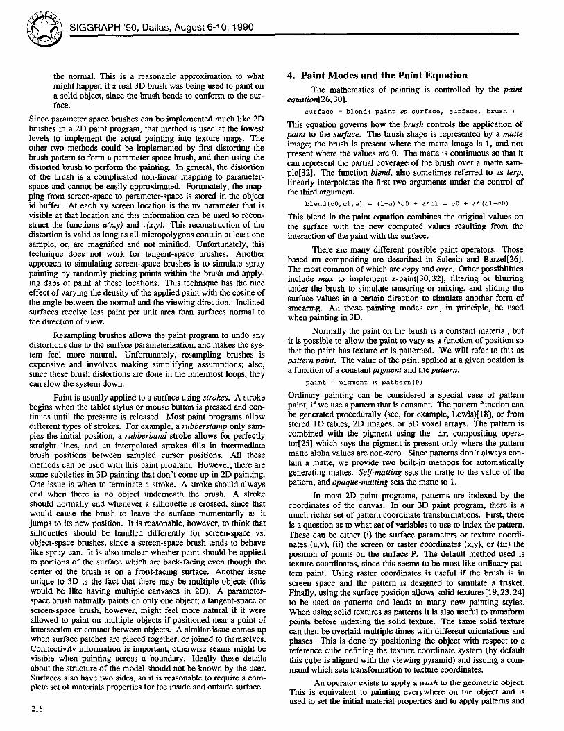
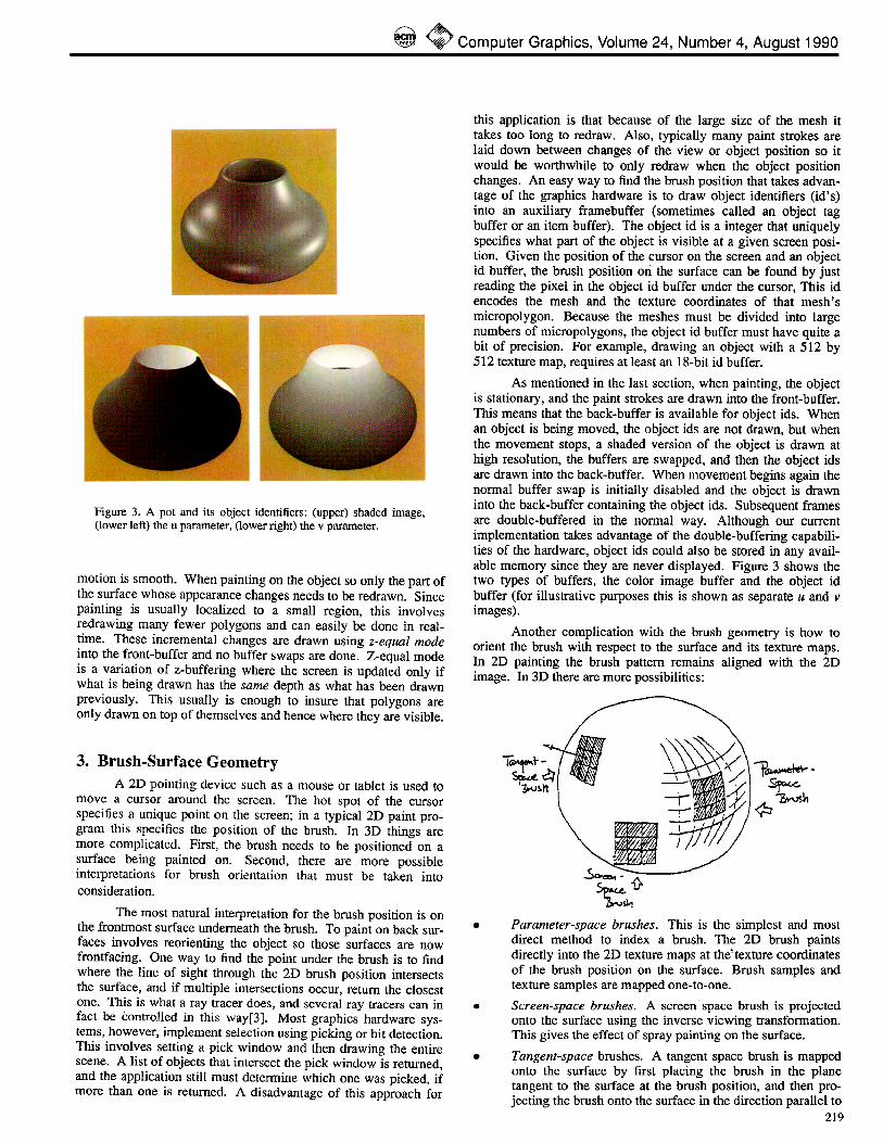
Figure 3. A pot and its object identifiers: (upper) shaded image, (lower left) the u parameter, (lower right) the v parameter.
motion is smooth. When painting on the object so only the part of the surface whose appearance changes needs to be redrawn. Since painting is usually localized to a small region, this involves redrawing many fewer polygons and can easily be done in real- time. These incremental changes are drawn using z-equal mode into the front-buffer and no buffer swaps are done. Z-equal mode is a variation of z-buffering where the screen is updated only if what is being drawn has the same depth as what has been drawn previously. This usually is enough to insure that polygons are only drawn on top of themselves and hence where they are visible.
3. B r u s h - S u r f a c e Geometry A 2D pointing device such as a mouse or tablet is used to
move a cursor around the screen. The hot spot of the cursor specifies a unique point on the screen; in a typical 2D paint pro- gram this specifies the position of the brush. In 3D things are more complicated. First, the brush needs to be positioned on a surface being painted on. Second, there are more possible interpretations for brush orientation that must be taken into consideration.
The most natural interpretation for the brush position is on the frontmost surface underneath the brush. To paint on back sur- faces involves reorienting the object so those surfaces are now frontfacing. One way to find the point under the brush is to find where the line of sight through the 2D brush position intersects the surface, and if multiple intersections occur, return the closest one. This is what a ray tracer does, and several ray tracers can in fact be Controlled in this way[3]. Most graphics hardware sys- tems, however, implement selection using picking or hit detection. This involves setting a pick window and then drawing the entire scene. A list of objects that intersect the pick window is returned, and the application still must determine which one was picked, if more than one is returned. A disadvantage of this approach for
this application is that because of the large size of the mesh it takes too long to redraw. Also, typically many paint strokes are laid down between changes of the view or object position so it would be worthwhile to only redraw when the object position changes. An easy way to find the brush position that takes advan- tage of the graphics hardware is to draw object identifiers (id's) into an auxiliary frarnebuffer (sometimes called an object tag buffer or an item buffer). The object id is a integer that uniquely specifies what part of the object is visible at a given screen posi- tion. Given the position of the cursor on the screen and an object id buffer, the brush position oti the surface can be found by just reading the pixel in the object id buffer under the cursor, This id encodes the mesh and the texture coordinates of that mesh's micropolygon. Because the meshes must be divided into large numbers of micropolygons, the object id buffer must have quite a bit of precision. For example, drawing an object with a 512 by 512 texture map, requires at least an 18-bit id buffer.
As mentioned in the last section, when painting, the object is stationary, and the paint strokes are drawn into the front-buffer. This means that the back-buffer is available for object ids. When an object is being moved, the object ids are not drawn, but when the movement stops, a shaded version of the object is drawn at high resolution, the buffers are swapped, and then the object ids are drawn into the back-buffer. When movement begins again the normal buffer swap is initially disabled and the object is drawn into the back-buffer containing the object ids. Subsequent flames are double-buffered in the normal way. Although our current implementation takes advantage of the double-buffering capabili- ties of the hardware, object ids could also be stored in any avail- able memory since they are never displayed. Figure 3 shows the two types of buffers, the color image buffer and the object id buffer (for illustrative purposes this is shown as separate u and v images).
Another complication with the brush geometry is how to orient the brush with respect to the surface and its texture maps. In 2D painting the brush pattern remains aligned with the 2D image. In 3D there are more possibilities:
• Parameter-space brushes. This is the simplest and most direct method to index a brush. The 2D brush paints directly into the 2D texture maps at the~texture coordinates of the brush position on the surface. Brush samples and texture samples are mapped one-to-one.
• Screen-space brushes. A screen space brush is projected onto the surface using the inverse viewing transformation. This gives the effect of spray painting on the surface.
• Tangent-space brushes. A tangent space brush is mapped onto the surface by first placing the brush in the plane tangent to the surface at the brush position, and then pro- jecting the brush onto the surface in the direction parallel to
219
SIGGRAPH '90, Dallas, August 6-10, 1990
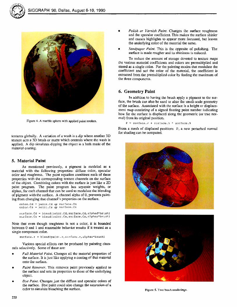
Figure 4. A marble sphere with applied paint strokes.
textures globally. A variation of a wash is a dip where another 3D texture acts a 3D brush or matte which controls where the wash is applied. A dip simulates dipping the object is a bath made of the material coating.
• Polish or Varnish Paint. Changes the surface roughness and the specular coefficient. This makes the surface shinier and causes highlights to appear more focussed, but leaves the underlying color of the material the same.
• Sandpaper Paint. This is the opposite of polishing. The surface is made rougher and its shininess is reduced.
To reduce the amount of storage devoted to texture maps the various material coefficients and colors are premultiplied and stored as a single color. For the painting modes that modulate the coefficient and not the color of the material, the coefficient is extracted from the premultiplied color by finding the maximum of the three components.
6. Geometry Paint In addition to having the brush apply a pigment to the sur-
face, the brush can also be used to alter the small-scale geometry of the surface. Associated with the surface is a height or displace- ment map consisting of a signed floating point number indicating how far the surface is displaced along the geometric (or true nor- mal) from its original position.
P = surface.P + surface.h * surface.N
From a mesh of displaced positions P, a new perturbed normal for shading can be computed.
5. Material Paint As mentioned previously, a pigment is modeled as a
material with the following properties: diffuse color, specular color and roughness. The paint equation combines each of these properties with the corresponding texture channels on the surface of the object. Combining colors with the surface is just like a 2D paint program. The paint program has separate weights, or alphas, for each channel that can be used to modulate the blending of pigment with the surface. A channel alpha of 0, prevents paint- ing from changing that channel's properties on the surface.
color.Cd = pain~.Cd op surface. Cd
color.C$ = paln~.Cs off surface. Cs
surface, ca = blend(color. Cd, surface. Cd, alphad*brush)
surface. Cs = blend ( color. Cs, surface. Cs, alphas*brush)
Note that even though roughness is not a color, it is bounded between 0 and 1 and reasonable behavior results if it treated as a single component color.
surface.r = blend (paint.r, surface.r, alphar*brush)
Various special effects can be produced by painting chan- nels selectively. Some of these are:
• Ful l Material Paint. Changes all the material properties of the surface. It is just like applying a coating of that material onto the surface.
• Paint Remover. This removes paint previously applied to the surface and sets its properties to those of the underlying object.
• Dye Paint. Changes just the diffuse and specular colors of the surface, Dye paint could also change the saturation of a color to simulate bleaching the surface.
220
Figure 5. Two batch renderings.
~ Computer Graphics, Volume 24, Number 4, August 1990
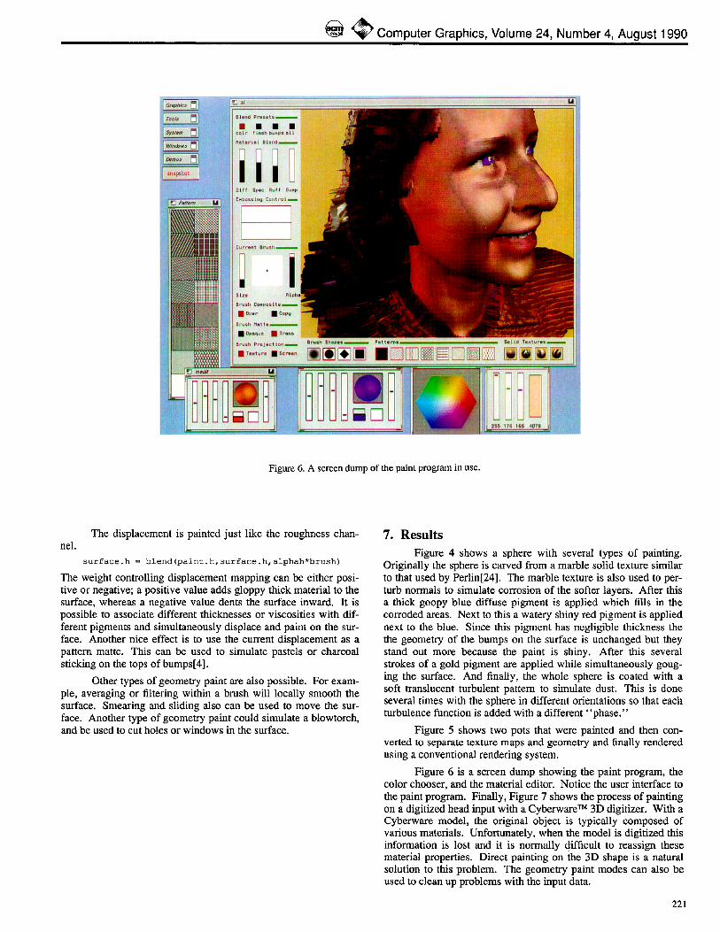
Figure 6. A screen dump of the paint program in use.
The displacement is painted just like the roughness chan- nel.
surface, h = blend (paint. h, surface, h, alphah*brush)
The weight controlling displacement mapping can be either posi- tive or negative; a positive value adds gloppy thick material to the surface, whereas a negative value dents the surface inward. It is possible to associate different thicknesses or viscosities with dif- ferent pigments and simultaneously displace and paint on the sur- face. Another nice effect is to use the current displacement as a pattern matte. This can be used to simulate pastels or charcoal sticking on the tops of bumps[4].
Other types of geometry paint are also possible. For exam- ple, averaging or filtering within a brush will locally smooth the surface. Smearing and sliding also can be used to move the sur- face. Another type of geometry paint could simulate a blowtorch, and be used to cut holes or windows in the surface.
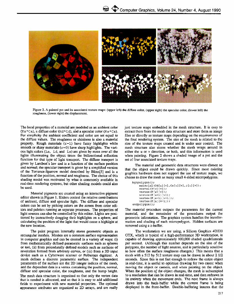
7. Results Figure 4 shows a sphere with several types of painting.
Originally the sphere is carved from a marble solid texture similar to that used by Perlin[24]. The marble texture is also used to per- turb normals to simulate corrosion of the softer layers. After this a thick goopy blue diffuse pigment is applied which fills in the corroded areas. Next to this a watery shiny red pigment is applied next to the blue. Since this pigment has negligible thickness the the geometry of the bumps on the surface is unchanged but they stand out more because the paint is shiny. After this several strokes of a gold pigment are applied while simultaneously goug- ing the surface. And finally, the whole sphere is coated with a soft translucent turbulent pattern to simulate dust. This is done several times with the sphere in different orientations so that each turbulence function is added with a different "phase ."
Figure 5 shows two pots that were painted and then con- verted to separate texture maps and geometry and finally rendered using a conventional rendering system.
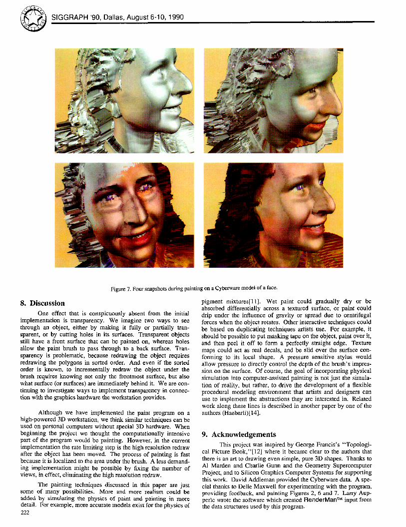
Figure 6 is a screen dump showing the paint program, the color chooser, and the material editor. Notice the user interface to the paint program. Finally, Figure 7 shows the process of painting on a digitized head input with a Cyberware TM 3D digitizer. With a Cyberware model, the original object is typically composed of various materials. Unfortunately, when the model is digitized this information is lost and it is normally difficult to reassign these material properties. Direct painting on the 3D shape is a natural solution to this problem. The geometry paint modes can also be used to clean up problems with the input data.
221
@ SIGGRAPH '90, Dallas, August 6-10, 1990
Figure 7. Four snapshots during painting on a Cyberware model of a face.
8. Discussion One effect that is conspicuously absent from the initial
implementation is transparency. We imagine two ways to see through an object, either by making it fully or partially tran- sparent, or by cutting holes in its surfaces. Transparent objects still have a front surface that can be painted on, whereas holes allow the paint brush to pass through to a back surface. Tran- sparency is problematic, because redrawing the object requires redrawing the polygons in sorted order. And even if the sorted order is known, to incrementally redraw the object under the brush requires knowing not only the frontmost surface, but also what surface (or surfaces) are immediately behind it. We are con- tinuing to investigate ways to implement transparency in connec- tion with the graphics hardware the workstation provides.
Although we have implemented the paint program on a high-powered 3D workstation, we think similar techniques can be used on personal computers without special 3D hardware. When beginning the project we thought the computationally intensive part of the program would be painting. However, in the current implementation the rate limiting step is the high resolution redraw after the object has been moved. The process of painting is fast because it is localized to the area under the brush. A less demand- ing implementation might be possible by fixing the number of views, in effect, eliminating the high resolution redraw.
The painting techniques discussed in this paper are just some of many possibilities. More and more realism could be added by simulating the physics of paint and painting in more detail. For example, more accurate models exist for the physics of 222
pigment mixtures[ll]. Wet paint could gradually dry or be absorbed differentially across a textured surface, or paint could drip under the influence of gravity or spread due to centrifugal forces when the object rotates. Other interactive techniques could be based on duplicating techniques artists use. For example, it should be possible to put masking tape on the object, paint over it, and then peel it off to form a perfectly straight edge. Texture maps could act as real decals, and be slid over the surface con- forming to its local shape. A pressure sensitive stylus would allow pressure to directly control the depth of the brush's impres- sion on the surface. Of course, the goal of incorporating physical simulation into computer-assisted painting is not just the simula- tion of reality, but rather, to drive the development of a flexible procedural modeling environment that artists and designers can use to implement the abstractions they are interested in. Related work along these lines is described in another paper by one of the authors (Haeberli)[14].
9. A c k n o w l e d g e m e n t s
This project was inspired by George Francis's "Topologi- cal Picture Book,"[12] where it became clear to the authors that there is an art to drawing even simple, pure 3D shapes. Thanks to A1 Marden and Charlie Gunn and the Geometry Supercomputer Project, and to Silicon Graphics Computer Systems for supporting this work. David Addleman provided the Cyberware data. A spe- cial thanks to Delle Maxwell for experimenting with the program, providing feedback, and painting Figures 2, 6 and 7. Larry Aup- perle wrote the software which created RenderMan "rM input from the data structures used by this program.
~ Computer Graphics, Volume 24, Number 4, August 1990
References 1. APPLE,, Human Interface Guideline: The Apple Oesktop
Interface, Addison-Wesley, Menlo Park (1987).
2. BASS, DANIEL H., "Using the Video Lookup Table for Reflectivity Calculations: Specific Techniques and Graph- ics Results," Computer Graphics and Image Processing 17(3) pp. 249-261 (1981).
3. BmR, ERIC A., "Skitters and Jacks: Interactive 3-D Posi- tioning Tools," Proceedings 1986 Workshop on Interac- tive 3-D Graphics, pp. 183-196 (October 1986).
4. BLESER, TERESA W., JOHN L. SIBERT, AND J. PATRICK MCGEE, "Charcoal Sketching: Returning Control to the Artist," ACM Transactions on Graphics 7(1)pp. 76-81 (January 1988).
5. BLn~N, JAMES F., "Models of Light Reflection for Com- puter Synthesized Pictures," Computer Graphics 11(2) pp. 192-198 (1977).
6. BLINN, JAMES F., "Simulation of Wrinkled Surfaces," Computer Graphics 12(3) pp. 286-292 (August 1978).
7. BL~N, JAMES F., "Raster Graphics," pp. 150-156 in Tutorial: Computer Graphics, ed. K. S. Booth, IEEE Press (1982).
8. CATMULL, EDWtN, "A Subdivision Algorithm for Com- puter Display of Curved Surfaces," Phd dissertation, University of Utah, Salt Lake City (1974).
9. CHEN, MICHAEL, S. JOY MUMFORD, AND ABIGAIL SELLEN, "A Study of Interactive 3-D Rotation Using 2-D Control Devices," Computer Graphics 22(4)pp. 121-129 (August 1988).
10. COOK, ROBERT L., "Shade Trees," Computer Graphics 18(3) pp. 223-231 (July 1984).
11. FISHKIN, KENNE'n-I, "An Application of Color Science to Computer Graphics," Master's Thesis, University of Cali- fornia, Berkeley, CA (1985).
12. FRANCIS, GEORGE K., A Topological Picturebook, Springer-Verlag, New York (1987).
13. GARDNER, GEOFFREY Y., "Visual Simulation of Clouds," Computer Graphics 19(3) pp. 297-303 (July 1985).
14. I-IAEBERLI, PAUL E., "Paint By Numbers: Abstract Image Representations," Computer Graphics, (24)(1990).
15. HECKBERT, PAUL S., "Techniques for Real-time Frame Buffer Animation," in Computer FX '84, , London (October 1984).
16. HECKBERT, PAUL S., "Survey of Texture Mapping," IEEE Computer Graphics and Applications 6(l l )pp. 56-67 (November 1986).
17. KAJIYA, JAMES T., "Anisotropic Reflection Models," Computer Graphics 19(3) pp. 15-22 (July 1985).
18. LEWlS, JOHN PETER, "Texture Synthesis for Digital Paint- ing," Computer Graphics 18(3) pp. 245-252 (July 1984).
19. LEWIS, JOHN P., "Algorithms for Solid Noise Synthesis," Computer Graphics 23(3) pp. 263-270 (July 1989).
20. MILLER, GAV~ S. P., "From Wire-Frames to Furry Animals," Graphics Interface "88, pp. 138-145 (1988).
21. NmLSON, GREGORY M. AND DAN R. OLSEN, JR., "Direct Manipulation Techniques for 3-D Objects Using 2-D Loca- tor Devices," Proceedings 1986 Workshop on Interactive
3-D Graphics, pp. 175-182 (October 1986).
22. NORMAN, DONALD A., The Psychology of Everyday Things, Basic Books, New York (1988).
23. PEACHEY, DARWYN, "Solid Texturing of Complex Sur- faces," Computer Graphics 19(3) pp. 279-286 (1985).
24. PERLIN, KEN, "An Image Synthesizer," Computer Graph- ics 19(3) pp. 287-296 (July 1985).
25. PORTER, THOMAS AND TOM DUFF, "Compositing Digital Images," Computer Graphics 18(3)pp. 253-260 (July 1984).
26. SALESIN, DAVID AND RONEN BARZEL, "Two-Bit Graph- ics," IEEE Computer Graphics and Applications, pp. 36-42 (June 1986).
27. SCHNEIDERMAN, BEN, "Direct Manipulation: A Step Beyond Programming Languages," 1EEL Computer 16(8) pp. 57-69 (1983).
28. SLOAN, KENNETH R. AND CHRISTOPHER M. BROWN, "Color Map Techniques," Computer Graphics and lmage Pro- cessing 13(4) pp. 297-317 (August 1979).
29. SM1TH, ALVY RAY, "Table Paint," in Siggaph '81 Tutorial Notes: Two-Dimensional Computer Animation, (August 1981).
30. SMITH, ALVY RAY, "Paint," pp. 501-512 in Tutorial: Computer Graphics, ed. K. S. Booth,IEEE Press (1982).
31. WARN, DAVID R., "Lighting Controls for Synthetic Images," Computer Graphics 17(3) pp. 13-21 (July 1983).
32. WHrFFED, TURNER, "Anti-aliased Line Drawing Using Brush Extrusion," Computer Graphics 17(3)pp. 151-156 (July t983).
33. WILLIAMS, LANCE, "3D Paint," Computer Graphics (Proceedings 1990 Symposium on Interactive 3D Tech- niques) 24(2) pp. 225-233 (March 1990).
223