direct™ - purkeys.net · volts, the issue is the charging system of the truck; allow the battery...
TRANSCRIPT

DIRECT™
DIAGNOSTIC GUIDE
INST030 Doc 3.02


1P: 479.419.4800 | F: 479.419.4801 | www.purkeys.net
CONTENTSGeneral Information ........................................................................2Direct Controller Call-Outs .............................................................3Wire Diagram and Legend .............................................................4Diagnostics .....................................................................................6 Excessive Voltage Drop Diagnostics ..................................6 Static Diagnostics ...............................................................7 Stinger/Aux Diagnostics .....................................................9 Charging Diagnostics ........................................................14Testing the DC/DC Converter ......................................................16Diagnostic Diagram ......................................................................19Summary .......................................................................................20Limited Commercial Warranty Policy ..........................................24

2
The Purkeys Direct™ system improves the charging of liftgate batteries by utilizing a DC/DC Converter to boost the voltage for optimal charging. The boost in voltage overcomes the normal voltage drop caused by the extended distance between the liftgate batteries and the vehicle charging system. Also, in cold temperatures batteries require increased charging voltages to maintain a high state of charge. The DC/DC Converter in the Direct system compensates for temperature as well as for voltage drop and provides the best voltage to the remotely located liftgate batteries. The result is well-charged liftgate batteries that will last longer and have ample power for liftgate operation.
The Direct system is automatic and has easy to interpret LED indicators to assure drivers and technicians of proper system function. The Direct Controller increases the time that the DC/DC Converter can charge the liftgate batteries by monitoring the source power and “extending” the liftgate battery charge time to take full advantage of the available power, without compromising the source batteries’ ability to crank the engine. Simply put, the Direct system provides opportunity charging for the liftgate batteries that is essential in low mileage, high frequency liftgate operation applications. The LED indicators clearly show the status of the source as well as the status of the liftgate batteries. A quick glance at the Direct Controller assures the driver that the liftgate batteries are ready to go, or alerts the driver that the batteries need maintenance.
GENERAL INFORMATION
3P: 479.419.4800 | F: 479.419.4801 | www.purkeys.net
DIRECT DIAGNOSTIC GUIDE
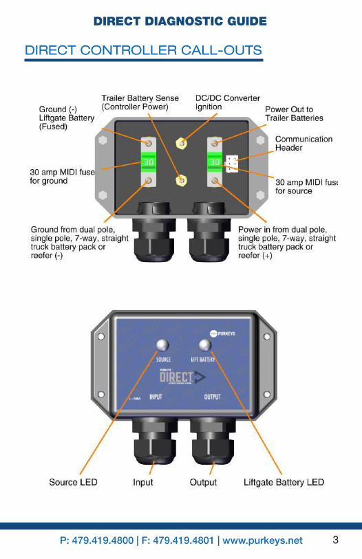
DIRECT CONTROLLER CALL-OUTS

4
WIRE DIAGRAM AND LEGEND
Component:
A. Liftgate Battery BoxB. Liftgate Battery PackC. P1020-K Liftgate Charging System Plate AssemblyD. 30 Amp Circuit BreakerE. DC/DC ConverterF. DC/DC Converter Output StudG. DC/DC Converter Input Stud (+)H. DC/DC Converter Input Stud (-)I. 2 Amp Inline Fuse from Liftgate BatteriesJ. Direct ControllerK. Input Source (Dual/Single Pole, 7-Way, Straight Truck Battery Pack, or Reefer Unit)

5P: 479.419.4800 | F: 479.419.4801 | www.purkeys.net
DIRECT DIAGNOSTIC GUIDE
WIRE COLOR
WIRE GAUGE CONNECT FROM CONNECT TO
Blue 10 Power In Input Source (+)White 10 Ground Input Source (-)
White 8 Ground Liftgate Battery (-) Fused
DC/DC Converter Input Stud (-)
Yellow 16 DC/DC Converter Ignition
DC/DC Converter Ignition Stud
Black 8Direct Controller
Power Out to DC/DC converter
DC/DC Converter Input (+)
Orange 14 Trailer Battery Sense (Controller Power)
Postive Liftgate Battery (+)

6
DIAGNOSTICS
If there is excessive voltage drop between the source battery and the Direct Controller, both Source and Lift Battery LEDs will briefly turn green, indicating that the Direct is trying to charge the batteries. Then both LEDs will toggle orange for a few seconds. This cycle then repeats (see Figure 1 for examples showing this issue).
EXCESSIVE VOLTAGE DROP DIAGNOSTICS
Figure 1: LEDs briefly turn green, toggle orange, then repeat
SERVICE TIP - Purkeys offers the Liftgate Double Check tool, which can simplify the diagnosis of liftgate charging system problems caused by excessive voltage drop. Formore information on the tool, please call 1-800-219-1269 or
visit our website at www.purkeys.net.
The circuit needs to be tested while under load to determine what is causing the excessive voltage drop. See the Stinger/Aux Diagnostics section for details on diagnosing excessive voltage drop issues.
7P: 479.419.4800 | F: 479.419.4801 | www.purkeys.net
DIRECT DIAGNOSTIC GUIDE
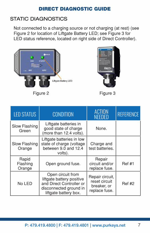
STATIC DIAGNOSTICS
Not connected to a charging source or not charging (at rest) (see Figure 2 for location of Liftgate Battery LED; see Figure 3 for LED status reference, located on right side of Direct Controller).
Figure 2 Figure 3
LED STATUS CONDITION ACTION NEEDED REFERENCE
Slow Flashing Green
Liftgate batteries in good state of charge
(more than 12.4 volts).None.
Slow Flashing Orange
Liftgate batteries in low state of charge (voltage between 9.0 and 12.4
volts).
Charge and test batteries.
Rapid Flashing Orange
Open ground fuse.Repair
circuit and/or replace fuse.
Ref #1
No LED
Open circuit from liftgate battery positive and Direct Controller or disconnected ground in
liftgate battery box.
Repair circuit, reset circuit breaker, or
replace fuse.
Ref #2

8
REFERENCE #1Rapid Flashing Orange LED: Repair ground circuit and/or replace ground fuse (see Figure 4 for ground fuse location).
Figure 4
Figure 5

9P: 479.419.4800 | F: 479.419.4801 | www.purkeys.net
DIRECT DIAGNOSTIC GUIDE
REFERENCE #2
No LED: Open circuit between liftgate battery positive or liftgate battery ground and the Direct Controller. Follow the steps below to diagnose the No LED Status (see Figure 5).
1. Using a voltmeter, measure the voltage between the positive post and the negative post on the liftgate battery (see V1 in Figure 5). If the reading is less than 12.0 V, charge or replace the batteries. If the battery is higher than 12.0 V, move to step 2.
2. Using a voltmeter, measure the voltage between the positive and negative studs on the plate inside the battery box (see V2 in Figure 5). If there is no voltage reading, the issue is either the circuit breaker or the wire from one of these studs to the circuit breaker. Reset the circuit breaker or repair/replace the wire. If there is battery voltage, move to step 3.
3. Using a voltmeter, measure the voltage between the ground stud from the 7-way and the liftgate battery positive stud inside the Direct Controller (see V3 in Figure 5). Liftgate battery voltage should read 12.0 or higher. If not, check the 2-amp fuse and replace if necessary. If there is still no voltage reading, repair or replace the wires between the battery box and the Direct Contoller. Once these steps are completed, if there are still no LEDs, call customer service, as the Direct Controller may not be functioning properly.
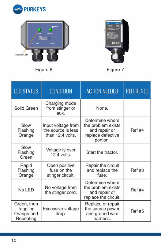
STINGER/AUX DIAGNOSTICS
Plug in the stinger and start the tractor (see Figure 6 for location of Source LED; see Figure 7 for LED status reference, located on right side of Direct Controller).
10
Figure 6 Figure 7
LED STATUS CONDITION ACTION NEEDED REFERENCE
Solid GreenCharging mode from stinger or
aux.None.
Slow Flashing Orange
Input voltage from the source is less than 12.4 volts.
Determine where the problem exists
and repair or replace defective
portion.
Ref #4
Slow Flashing Green
Voltage is over 12.4 volts. Start the tractor.
Rapid Flashing Orange
Open positive fuse on the
stinger circuit.
Repair the circuit and replace the
fuse.Ref #3
No LED No voltage from the stinger cord.
Determine where the problem exists
and repair or replace the circuit.
Ref #4
Green, then Toggling
Orange and Repeating
Excessive voltage drop.
Replace or repair the source power and ground wire
harness.
Ref #5

11P: 479.419.4800 | F: 479.419.4801 | www.purkeys.net
DIRECT DIAGNOSTIC GUIDE
REFERENCE #3Rapid Flashing Orange LED: Blown fuse on the stinger circuit. Replace the fuse (see Figure 8 for source fuse location).
Figure 8
Note: For systems that utilize the aux circuit and a 7-way cord, tractor manufactures have typically used 30 amp fuses on the aux circuit, but some older vehicles may have a 20-25 amp fuse or circuit breaker. Over time, these devices deteriorate and lose their ability to carry the rated amount of current. This can cause the fuse or circuit breaker to open, turning off power to the circuit. If this is occurring, replace the fuse or circuit breaker with a new unit and test the system.

12
Figure 10
Figure 9
13P: 479.419.4800 | F: 479.419.4801 | www.purkeys.net
DIRECT DIAGNOSTIC GUIDE
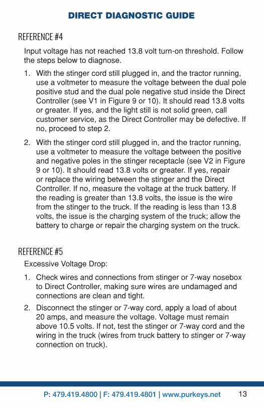
REFERENCE #4Input voltage has not reached 13.8 volt turn-on threshold. Follow the steps below to diagnose.
1. With the stinger cord still plugged in, and the tractor running, use a voltmeter to measure the voltage between the dual pole positive stud and the dual pole negative stud inside the Direct Controller (see V1 in Figure 9 or 10). It should read 13.8 volts or greater. If yes, and the light still is not solid green, call customer service, as the Direct Controller may be defective. If no, proceed to step 2.
2. With the stinger cord still plugged in, and the tractor running, use a voltmeter to measure the voltage between the positive and negative poles in the stinger receptacle (see V2 in Figure 9 or 10). It should read 13.8 volts or greater. If yes, repair or replace the wiring between the stinger and the Direct Controller. If no, measure the voltage at the truck battery. If the reading is greater than 13.8 volts, the issue is the wire from the stinger to the truck. If the reading is less than 13.8 volts, the issue is the charging system of the truck; allow the battery to charge or repair the charging system on the truck.
REFERENCE #5Excessive Voltage Drop:
1. Check wires and connections from stinger or 7-way nosebox to Direct Controller, making sure wires are undamaged and connections are clean and tight.
2. Disconnect the stinger or 7-way cord, apply a load of about 20 amps, and measure the voltage. Voltage must remain above 10.5 volts. If not, test the stinger or 7-way cord and the wiring in the truck (wires from truck battery to stinger or 7-way connection on truck).

14
SERVICE TIP - Purkeys offers the Liftgate Double Check tool, which can simplify the diagnosis of liftgate charging system problems caused by excessive voltage drop. Formore information on the tool, please call 1-800-219-1269 or
visit our website at www.purkeys.net.
7-Way Nosebox Tips:
• Inspect circuits inside the 7-way box for excessive electrical resistance caused by overheating, corrosion, loose/poor connections, or undersized wiring.
• Check to see if the 7-way nosebox is equipped with circuit breakers (see Figure 11), as the problem may be a failing circuit breaker. Either replace circuit breaker with a new part or connect the blue wire from the Direct Controller to the unprotected side of the circuit breaker. Circuit protection is provided by the 30 amp fuse inside the Direct Controller.
• Ensure the 7-way or stinger cord has a tight fit and has good electrical contact at the tractor and trailer receptacles.
Figure 11: 7-Way Nosebox

15P: 479.419.4800 | F: 479.419.4801 | www.purkeys.net
DIRECT DIAGNOSTIC GUIDE
CHARGING DIAGNOSTICS
Charging from the source (the source LED is Solid Green). The Lift Battery LED status is as listed in table below (see Figure 12 for location of Liftgate Battery LED; see Figure 13 for LED status reference located, on right side of Direct Controller.)
Figure 12 Figure 13
LED STATUS CONDITION ACTION NEEDED REFERENCESolid Green Charging. None.
Slow Flashing Green
Good battery voltage, but may not
be charging.
Check the DC/DC Converter
and circuit protection.
Page 16
Slow Flashing Orange
Low battery, but may not be charging.
Check the DC/DC Converter
and circuit protection.
Page 16
No LED
Open circuit from liftgate battery positive and
Direct Controller or disconnected ground in liftgate
battery box.
Repair circuit, reset circuit breaker, or
replace fuse.
Ref #2

16
TESTING THE DC/DC CONVERTER
See Figure 14 to see the LED on the DC/DC converter. A rapid flashing red LED on the converter is normal if the trailer is disconnected from a running truck. It will continue to flash for a short period of time. A rapid flashing red LED is only a fault if the trailer is connected to a running truck.
Figure 14
LED STATUS CONDITION ACTION NEEDED REFERENCE
Solid GreenDC/DC
Converter is on.
Ensure circuit protection on 30 amp circuit breaker is in
working order.
Ref #9
Rapid Flashing Red
DC/DC Converter has
a fault.Determine the fault. Ref #9 and
10
No Light No voltage. Determine the fault. Ref #9 and 10

17P: 479.419.4800 | F: 479.419.4801 | www.purkeys.net
DIRECT DIAGNOSTIC GUIDE
REFERENCE #9Steps to test power to the DC/DC Converter:
REFERENCE #10Steps to testing the DC/DC Converter:
1. Look at the Source LED on the Direct Controller and ensure that it is Solid Green. If no, refer to the Stinger or Aux Diagnostics sections. If yes, measure the voltage at the DC/DC Converter Input (+) stud and Ground (-) Liftgate Battery (Fused) stud (see V1 on Figure 15). Voltage should be over 10.0 volts. If yes, go to step 2. If no, check 30 amp MIDI fuses for the stinger or aux.
2. With a voltmeter, measure the voltage at the ignition output (see V2 on Figure 15). Should be over 10.0 volts. If yes, skip to step 3. If no, replace Direct Contoller.
3. With a voltmeter, measure the input and ignition voltages at the P1020-K Liftgate Charging System Plate Assembly (see V3 and V4 on Figure 15). Both should be over 10.0 volts. If no, repair or replace the wires between the Direct Controller and the P1020-K Liftgate Charging System Plate Assembly. If both voltages are over 10.0 volts, move to reference 10.
1. After completing the steps in Reference #9, check the circuit breaker. Reset the circuit breaker if tripped.
2. Check to verify that the DC/DC converter is charging the batteries. This can be done by measuring the voltage at the battery or by measuring the current going to the battery. If the voltage is above 14.0 volts, OR if the voltage is rising over time, OR if current is flowing into the battery, the DC/DC converter is charging the batteries. See a, b, or c below for details on how to make these measurements.
a. Measure the voltage at the liftgate batteries (see V5 on Figure 15). If higher than 14.0 volts, the charging system is functioning properly.

18
b. If the voltage at the liftgate batteries is below 14.0 volts, use a voltmeter to monitor the voltage at the liftgate batteriesfor2–5minutes(seeV5onFigure15).Ifthevoltage rises, the DC/DC converter is functioning properly; allow time for the batteries to charge.
If the DC/DC converter is not charging, check the wiring and connections to the DC/DC converter. If problem continues, replace the DC/DC converter.
c. Using a clip-on ammeter, measure current flow (see clip-on ammeter on Figure 15). If above 10.0 amps, the system is working. Allow time for the liftgate batteries to charge.
NOTE: If the voltage at the liftgate batteries is above 14.0 volts, and the batteries are fully charged, the current will taper down to under 10.0 amps.

19P: 479.419.4800 | F: 479.419.4801 | www.purkeys.net
DIRECT DIAGNOSTIC GUIDE
DIAGNOSTIC DIAGRAM
Figure 15

20
SUMMARY
LED Status Logic
Solid Green on Lift Battery and Source
ChargingState–Sourcevoltagewas greater than 13.8 volts. DC/DC converter is on. Tractor must be running and alternator good
to achieve 13.8 volts. A batteries surface charge cannot reach this
value.
Note: The turn on voltage is 13.2 volts after 5 mins or 13.8 volts
immediately. Reason is that if in Dual Pole in Parallel state, the
Select input is now connected to liftgate batteries via the dual pole cables. If the liftgate batteries had been charging using the DC/DC
converter, then that voltage could be above 13.2 volts.
Solid Green on Source
Slow Flashing Orange on Lift
Battery
Charging State - Tractor connected and running. DC/DC converter is operating but the liftgate batteries are defective or below 12.8 volts.
Solid Green on Lift Battery and Source
ExtendState–Sourcevoltagedrops below 13.8 volts. DC/DC converter is on for 1 hour. Every
two minutes the controller turns off the DC/DC converter so there is no current flow (no voltage drop) and measures the battery voltage
on the tractor batteries. If over 12.4 volts, the controller turns on for another two minutes. This will
repeat until 60 minutes has expired or the battery voltage drops below
12.4 volts.

21P: 479.419.4800 | F: 479.419.4801 | www.purkeys.net
DIRECT DIAGNOSTIC GUIDE
LED Status Logic
Dual Pole in Parallel Mode
Solid Green on Lift Battery and Source
ExtendState–Tractorturnsoffor voltage drops below 12.6 volts
(dual pole coupled, but engine off). Then it will extend for approx. 2
minutes and turn off. If voltage at dual pole does not drop below 12.6
volts, then the Direct will extend until 60 minutes has expired.
No Source LED
Lift Battery LED Slow Flashing Green
Static State - No tractor connected to the trailer and the liftgate
batteries are more than 12.4 volts.
No Source LED
Lift Battery LED Slow Flashing Orange
Static State - No tractor connected to the trailer and the liftgate
batteries are less than 12.4 volts.
Slow Flashing Green on Lift Battery and
Source
OffState–Sourcevoltagebelow13.8 volts and extend period is over. Voltage at the lift batteries
and the source is above 12.4 volts. Voltage at source must achieve 13.8 volts to go into Charging
State.
Slow Flashing Orange on Lift
Battery and Source
OffState(LowVoltage)–Liftbattery and source voltage below 12.4 volts. DC/DC converter is off.
Voltage at source must achieve 13.8 volts to go into Charging
State.
Rapid Flashing
Orange on Lift Battery and/or
Source
OffState(Fault)–Blowngroundfuse if flashing on lift battery and blown source fuse if flashing on
source.

22
LED Status Logic
No LED
OffState(Fault)–Opencircuitin lift battery or source circuit.
This could also be caused by the liftgate battery voltage being below
6 volts.
ExcessiveVoltageDrop–Tractoris running and the voltage is above 13.8 volts. The controller turns on the DC/DC converter and current starts to flow. If the voltage drops
below 10.5 volts, the controller will tell the DC/DC converter to
turn off. What the operator will see is the Source and Lift Battery go Solid Green. Then both LEDs will toggle orange for a few seconds.
The cycle then repeats.
Note: Low voltage shut off in the 1st 5 mins is 9.5 volts.

23P: 479.419.4800 | F: 479.419.4801 | www.purkeys.net
DIRECT DIAGNOSTIC GUIDE

24
LIMITED COMMERCIAL WARRANTY POLICYPurkeys Fleet Electric, Inc. (hereafter “Purkeys”), warrants each product to be free of defects in material or workmanship under normal use and service. This warranty is for the benefit of Original Equipment Manufacturers, Dealers, Warehouse Distributors, Fleets, or other End Users (hereafter “Customers”) and covers products manufactured by Purkeys and sold new to Customers either directly by Purkeys or by its authorized dealers, distributors, or agents. The length of the Warranty Period is 36 months.
The warranty period commences on the in-service or install date and is not transferable. Failure to provide the in-service or install date on the warranty claim form will cause the warranty period to begin on the date the part was manufactured or date of sale recorded on the original sales invoice, whichever is earlier.
A completed warranty claim form should accompany all parts submitted to Purkeys for consideration for repair or replacement under warranty. The submitted claim form should contain all of the information required. Lack of a properly or fully completed claim form will result in delay or denial of warranty claim. Claims must be submitted no later than 30 days after part is removed.
This warranty does not apply if, in sole judgement of Purkeys, the product has been damaged or subjected to accident, faulty repair, improper adjustment, improper installation or wiring, neglect, misuse, or alteration or if the product failure is caused by defects in peripheral vehicle components or components attached to the Product or failure of a part not manufactured by Purkeys.
This warranty shall not apply if any Purkeys product is used for a purpose for which it is not designed or is in any way altered without the specific prior written consent of Purkeys. ANY Product alleged by a Customer to be defective must be inspected by Purkeys as a part of the warranty claims process in order to confirm that the part has failed as a result of a defect in material or workmanship.
Transportation for products and parts submitted to Purkeys for warranty consideration must be prepaid by Customer. Repaired or replaced products and or components will be returned to Customer pre-paid by Customer or “freight collect” to the address provided by Customer in the warranty claim form. No charge will be made for labor or material in effecting such repairs.
The Warranty provided by Purkeys hereunder is specifically limited to repair or replacement of the Product as Purkeys deems most appropriate in its sole discretion. Purkeys neither assumes nor authorizes any other person to assume on its behalf any other warranty or liabilities in connection with Purkeys products. The Warranty does not apply to fuses or other “consumable” or maintenance items which are or may be a part of any Purkeys product.
THIS WARRANTY DOES NOT APPLY TO LOSS OF VEHICLE OR EQUIPMENT, LOSS OF TIME, INCONVENIENCE, OR OTHER INCIDENTAL OR CONSEQUENTIAL DAMAGES. PURKEYS SPECIFICALLY DISCLAIMS AND SHALL NOT BE LIABLE FOR INCIDENTAL OR CONSEQUENTIAL DAMAGES arising out of or from the use of Purkeys products by the Customer.
THIS LIMITED WARRANTY IS IN LIEU OF ALL OTHER WARRANTIES, INCLUDING COMMON LAW WARRANTIES OF FITNESS FOR A PARTICULAR PURPOSE, MERCHANTABILITY, AND ANY OTHER EXPRESS OR IMPLIED WARRANTIES. ALL OTHER SUCH WARRANTIES ARE SPECIFICALLY DISCLAIMED.
This Limited Commercial Warranty supersedes all previous Warranty Policies issued by Purkeys and any of its suppliers.

25P: 479.419.4800 | F: 479.419.4801 | www.purkeys.net
DIRECT DIAGNOSTIC GUIDE
