directed energy weapons in modern battlefield - advances in
TRANSCRIPT
Advances in Military Technology Vol. 4, No. 2, December 2009
Directed Energy Weapons in Modern Battlefield
L. Palíšek*
Division VTÚPV Vyškov, VOP-026 Šternberk, s.p., Czech Republic
The manuscript was received on 25 June 2009 and was accepted after revision for publication on 21 September 2009.
Abstract:
The paper deals with electromagnetic threats caused due to Directed Energy Weapons (DEW). The area of interest is focused on HPM (High Power Microwaves) and UWB (Ultra Wide Bandwidth) as an important part of DEW area. Possible impact on electronic structures which can be part of military systems is considered in this paper. Some practical results achieved during experiments related to assessment of electronic equipment vulnerability is provided with overview of immunity of some equipment to HPM and UWB signals at the end of this study.
Keywords:
DEW, HPM, UWB, electromagnetic threats, NEC, vulnerability
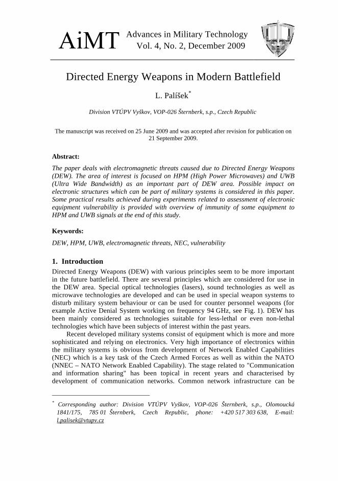
1. Introduction Directed Energy Weapons (DEW) with various principles seem to be more important in the future battlefield. There are several principles which are considered for use in the DEW area. Special optical technologies (lasers), sound technologies as well as microwave technologies are developed and can be used in special weapon systems to disturb military system behaviour or can be used for counter personnel weapons (for example Active Denial System working on frequency 94 GHz, see Fig. 1). DEW has been mainly considered as technologies suitable for less-lethal or even non-lethal technologies which have been subjects of interest within the past years.
Recent developed military systems consist of equipment which is more and more sophisticated and relying on electronics. Very high importance of electronics within the military systems is obvious from development of Network Enabled Capabilities (NEC) which is a key task of the Czech Armed Forces as well as within the NATO (NNEC – NATO Network Enabled Capability). The stage related to "Communication and information sharing" has been topical in recent years and characterised by development of communication networks. Common network infrastructure can be
* Corresponding author: Division VTÚPV Vyškov, VOP-026 Šternberk, s.p., Olomoucká
1841/175, 785 01 Šternberk, Czech Republic, phone: +420 517 303 638, E-mail: [email protected]
56 L. Palíšek
considered as a fundament of integrated NEC environment. Communication network and especially its reliability will have significant influence on mission success. Disturbance of these networks could be obviously critical.
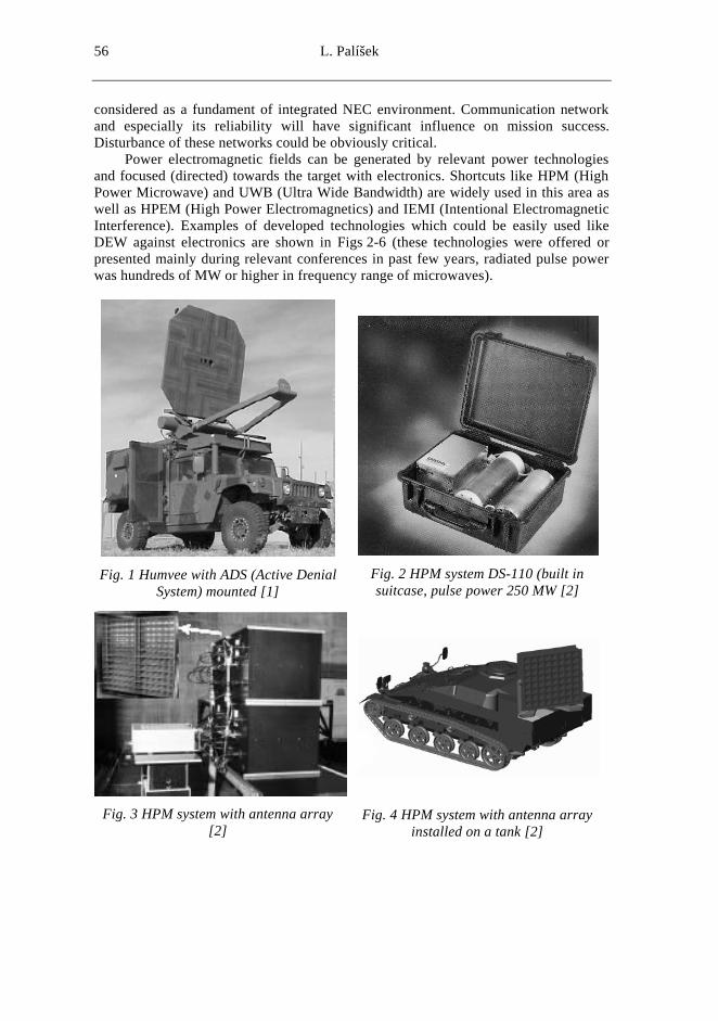
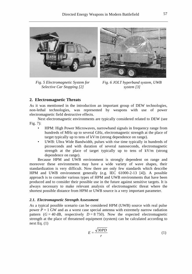
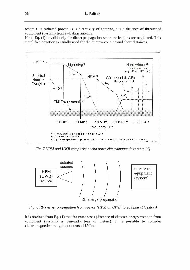
Power electromagnetic fields can be generated by relevant power technologies and focused (directed) towards the target with electronics. Shortcuts like HPM (High Power Microwave) and UWB (Ultra Wide Bandwidth) are widely used in this area as well as HPEM (High Power Electromagnetics) and IEMI (Intentional Electromagnetic Interference). Examples of developed technologies which could be easily used like DEW against electronics are shown in Figs 2-6 (these technologies were offered or presented mainly during relevant conferences in past few years, radiated pulse power was hundreds of MW or higher in frequency range of microwaves).
Fig. 1 Humvee with ADS (Active Denial
System) mounted [1]
Fig. 2 HPM system DS-110 (built in suitcase, pulse power 250 MW [2]
Fig. 3 HPM system with antenna array
[2]
Fig. 4 HPM system with antenna array installed on a tank [2]
57 57
Directed Energy Weapons in Modern Battlefield
Fig. 5 Electromagnetic System for Selective Car Stopping [2]
Fig. 6 JOLT hyperband system, UWB system [3]
2. Electromagnetic Threats As it was mentioned in the introduction an important group of DEW technologies, non-lethal technologies, was represented by weapons with use of power electromagnetic field destructive effects.
Next electromagnetic environments are typically considered related to DEW (see Fig. 7):
• HPM: High Power Microwaves, narrowband signals in frequency range from hundreds of MHz up to several GHz, electromagnetic strength at the place of target typically up to tens of kV/m (strong dependence on range).
• UWB: Ultra Wide Bandwidth, pulses with rise time typically in hundreds of picoseconds and with duration of several nanoseconds, electromagnetic strength at the place of target typically up to tens of kV/m (strong dependence on range).
Because HPM and UWB environment is strongly dependent on range and moreover these environments may have a wide variety of wave shapes, their standardization is very difficult. Now there are only few standards which describe HPM and UWB environment generally (e.g. IEC 61000-2-13 [4]). A possible approach is to consider various types of HPM and UWB environments that have been produced and to consider their possible use in the future against sensitive targets. It is always necessary to make relevant analysis of electromagnetic threat where the shortest possible distance from HPM or UWB source is a very important parameter.
2.1. Electromagnetic Strength Assessment As a typical possible scenario can be considered HPM (UWB) source with real pulse power P = 1 GW and as a worst case special antenna with extremely narrow radiation pattern (G = 40 dB, respectively D = 8 750). Now the expected electromagnetic strength at the place of threatened equipment (system) can be calculated according to next Eq. (1)
rPDE 30
= (1)
58 L. Palíšek
where P is radiated power, D is directivity of antenna, r is a distance of threatened equipment (system) from radiating antenna. Note: Eq. (1) is valid only for direct propagation where reflections are neglected. This simplified equation is usually used for the microwave area and short distances.
Fig. 7 HPM and UWB comparison with other electromagnetic threats [4]
HPM (UWB) source
radiated antenna threatened
equipment (system)
RF energy propagation
Fig. 8 RF energy propagation from source (HPM or UWB) to equipment (system)
It is obvious from Eq. (1) that for most cases (distance of directed energy weapon from equipment (system) is generally tens of meters), it is possible to consider electromagnetic strength up to tens of kV/m.
59 59
Directed Energy Weapons in Modern Battlefield
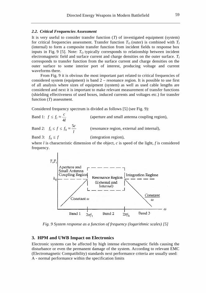
2.2. Critical Frequencies Assessment It is very useful to consider transfer function (T) of investigated equipment (system) for critical frequencies assessment. Transfer function TO (outer) is combined with TI (internal) to form a composite transfer function from incident fields to response box inputs in Fig. 9 [5]. Note: TO typically corresponds to relationship between incident electromagnetic field and surface current and charge densities on the outer surface. TI corresponds to transfer function from the surface current and charge densities on the outer surface to some interior port of interest, producing voltage and current waveforms there.
From Fig. 9 it is obvious the most important part related to critical frequencies of considered system (equipment) is band 2 – resonance region. It is possible to use first of all analysis where sizes of equipment (system) as well as used cable lengths are considered and next it is important to make relevant measurement of transfer functions (shielding effectiveness of used boxes, induced currents and voltages etc.) for transfer function (T) assessment. Considered frequency spectrum is divided as follows [5] (see Fig. 9):
Band 1: l
cff l 4≈≤ (aperture and small antenna coupling region),
Band 2: lcfff h
51 ≈≤≤ (resonance region, external and internal),
Band 3: ffh ≤ (integration region), where l is characteristic dimension of the object, c is speed of the light, f is considered frequency.
Fig. 9 System response as a function of frequency (logarithmic scales) [5]
3. HPM and UWB Impact on Electronics Electronic systems can be affected by high intense electromagnetic fields causing the disturbance or even the permanent damage of the system. According to relevant EMC (Electromagnetic Compatibility) standards next performance criteria are usually used: A - normal performance within the specification limits
60 L. Palíšek
B - temporary loss or degradation of function (self-recoverable) C - temporary loss of degradation of function, which requires operator intervention or resetting D - degradation or loss of function which is not recoverable due to damage of equipment (components) or software damage
On the one hand performance criteria are a very important parameter on the other hand consequence of IEMI (Intentional Electromagnetic Interference) attack has to be considered too. For consequence scaling it is possible to use for example such terms like "very limited", "limited", "severe", "very severe" and "catastrophic" [6].
4. Vulnerability Assessment First of all it is necessary to make analysis where electromagnetic threat assessment is done (see chapter 2). Moreover it is necessary to consider criticality of relevant system (consequences – see chapter 3). Finally testing plan and testing can be prepared. The best way is to start with transfer function measurements (shielding effectiveness measurement, induced currents and voltages measurement) which is possible to carry out in wide frequency range up to few GHz or higher. After that it is necessary to choose possible critical frequencies according to transfer function measurements and according to analysis. Chosen frequencies can be used for final high power electromagnetic field measurement with HPM and UWB simulator use. Possibilities of these simulators are restricted to parameters which cannot be changed or changing these parameters takes too much time. Due to this fact it is necessary to choose suitable parameters according to analysis and transfer function measurement results for this testing. The data gained from analyses and testing has to be considered together with possible consequences which can occur. Such data can be used for vulnerability assessment.
5. Practical Results A lot of experiments related to electronic equipment vulnerability have been carried out in previous projects within the last few years.
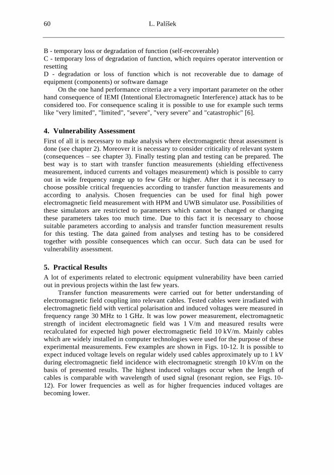
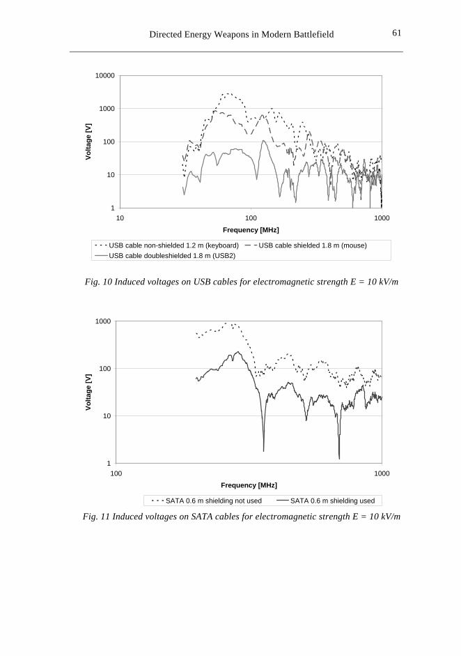
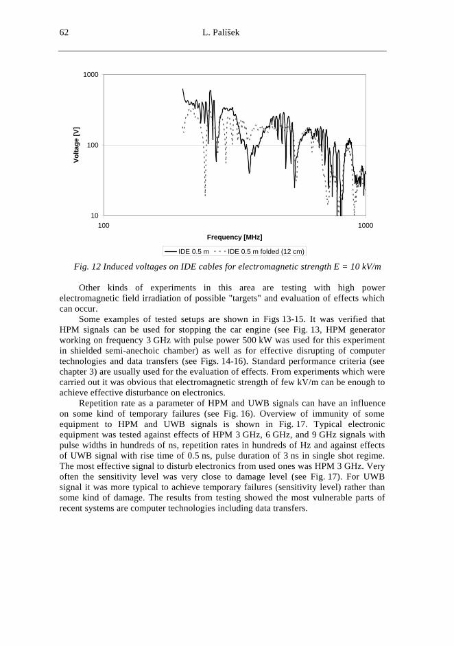
Transfer function measurements were carried out for better understanding of electromagnetic field coupling into relevant cables. Tested cables were irradiated with electromagnetic field with vertical polarisation and induced voltages were measured in frequency range 30 MHz to 1 GHz. It was low power measurement, electromagnetic strength of incident electromagnetic field was 1 V/m and measured results were recalculated for expected high power electromagnetic field 10 kV/m. Mainly cables which are widely installed in computer technologies were used for the purpose of these experimental measurements. Few examples are shown in Figs. 10-12. It is possible to expect induced voltage levels on regular widely used cables approximately up to 1 kV during electromagnetic field incidence with electromagnetic strength 10 kV/m on the basis of presented results. The highest induced voltages occur when the length of cables is comparable with wavelength of used signal (resonant region, see Figs. 10-12). For lower frequencies as well as for higher frequencies induced voltages are becoming lower.
61 61
Directed Energy Weapons in Modern Battlefield
1
10
100
1000
10000
10 100 1000
Frequency [MHz]
Volta
ge [V
]
USB cable non-shielded 1.2 m (keyboard) USB cable shielded 1.8 m (mouse)USB cable doubleshielded 1.8 m (USB2)
Fig. 10 Induced voltages on USB cables for electromagnetic strength E = 10 kV/m
1
10
100
1000
100 1000
Frequency [MHz]
Volta
ge [V
]
SATA 0.6 m shielding not used SATA 0.6 m shielding used Fig. 11 Induced voltages on SATA cables for electromagnetic strength E = 10 kV/m
62 L. Palíšek
10
100
1000
100 1000
Frequency [MHz]
Volta
ge [V
]
IDE 0.5 m IDE 0.5 m folded (12 cm) Fig. 12 Induced voltages on IDE cables for electromagnetic strength E = 10 kV/m
Other kinds of experiments in this area are testing with high power
electromagnetic field irradiation of possible "targets" and evaluation of effects which can occur.
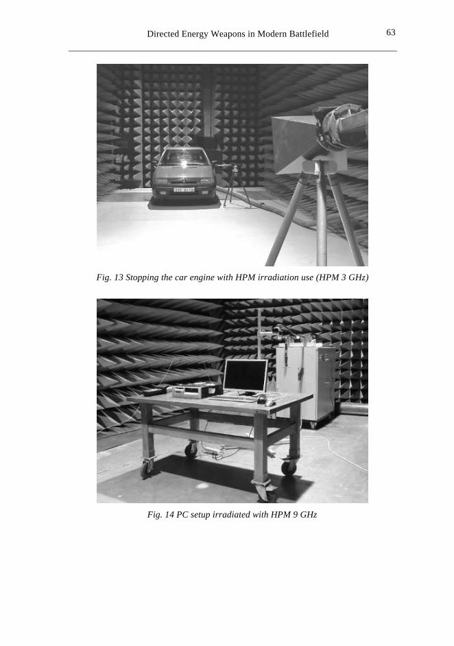
Some examples of tested setups are shown in Figs 13-15. It was verified that HPM signals can be used for stopping the car engine (see Fig. 13, HPM generator working on frequency 3 GHz with pulse power 500 kW was used for this experiment in shielded semi-anechoic chamber) as well as for effective disrupting of computer technologies and data transfers (see Figs. 14-16). Standard performance criteria (see chapter 3) are usually used for the evaluation of effects. From experiments which were carried out it was obvious that electromagnetic strength of few kV/m can be enough to achieve effective disturbance on electronics.
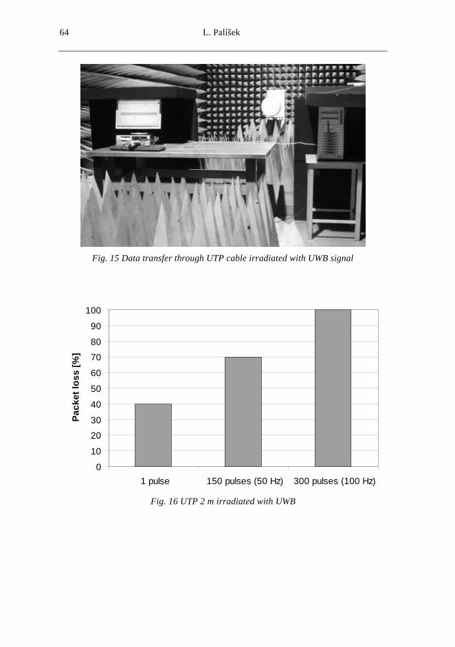
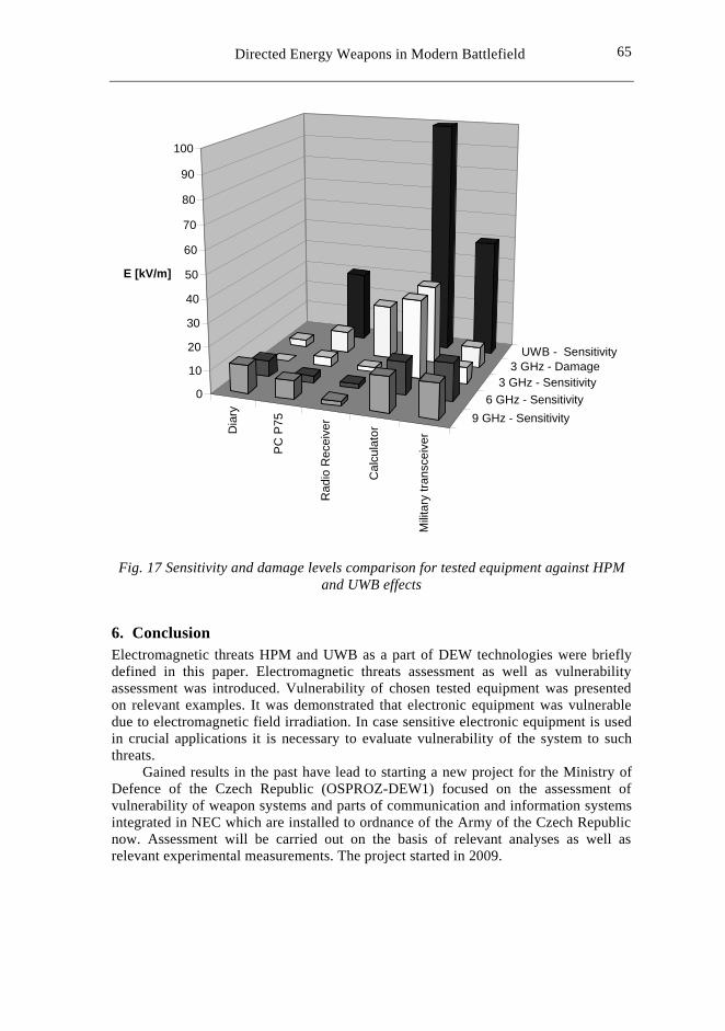
Repetition rate as a parameter of HPM and UWB signals can have an influence on some kind of temporary failures (see Fig. 16). Overview of immunity of some equipment to HPM and UWB signals is shown in Fig. 17. Typical electronic equipment was tested against effects of HPM 3 GHz, 6 GHz, and 9 GHz signals with pulse widths in hundreds of ns, repetition rates in hundreds of Hz and against effects of UWB signal with rise time of 0.5 ns, pulse duration of 3 ns in single shot regime. The most effective signal to disturb electronics from used ones was HPM 3 GHz. Very often the sensitivity level was very close to damage level (see Fig. 17). For UWB signal it was more typical to achieve temporary failures (sensitivity level) rather than some kind of damage. The results from testing showed the most vulnerable parts of recent systems are computer technologies including data transfers.
63 63
Directed Energy Weapons in Modern Battlefield
Fig. 13 Stopping the car engine with HPM irradiation use (HPM 3 GHz)
Fig. 14 PC setup irradiated with HPM 9 GHz
64 L. Palíšek
Fig. 15 Data transfer through UTP cable irradiated with UWB signal
0
10
20
30
40
50
60
70
80
90
100
1 pulse 150 pulses (50 Hz) 300 pulses (100 Hz)
Pack
et lo
ss [%
]
Fig. 16 UTP 2 m irradiated with UWB
65 65
Directed Energy Weapons in Modern Battlefield
Dia
ry
PC
P75
Rad
io R
ecei
ver
Cal
cula
tor
Milit
ary
trans
ceiv
er9 GHz - Sensitivity
6 GHz - Sensitivity3 GHz - Sensitivity
3 GHz - DamageUWB - Sensitivity
0
10
20
30
40
50
60
70
80
90
100
E [kV/m]
Fig. 17 Sensitivity and damage levels comparison for tested equipment against HPM
and UWB effects
6. Conclusion Electromagnetic threats HPM and UWB as a part of DEW technologies were briefly defined in this paper. Electromagnetic threats assessment as well as vulnerability assessment was introduced. Vulnerability of chosen tested equipment was presented on relevant examples. It was demonstrated that electronic equipment was vulnerable due to electromagnetic field irradiation. In case sensitive electronic equipment is used in crucial applications it is necessary to evaluate vulnerability of the system to such threats.
Gained results in the past have lead to starting a new project for the Ministry of Defence of the Czech Republic (OSPROZ-DEW1) focused on the assessment of vulnerability of weapon systems and parts of communication and information systems integrated in NEC which are installed to ordnance of the Army of the Czech Republic now. Assessment will be carried out on the basis of relevant analyses as well as relevant experimental measurements. The project started in 2009.
66 L. Palíšek
References [1] Wikipedia [online]. Wikipedia, the Free Encyclopaedia. [cited 2009-09-15].
Available from: <http://en.wikipedia.org/wiki/Active_Denial_System>. [2] DIEHL Defence [online]. DIEHL Defence. [cited 2009-09-15]. Available from:
<http://www.diehl-bgt-defence.de>. [3] GIRI, DV. High – Power Electromagnetic Radiators: Nonlethal Weapons and
Other Applications. Cambridge (Massachusetts) and London : Harvard University Press, 2004. 194 p. ISBN 0-674-01569-X.
[4] International Standard IEC 61000-2-13 Electromagnetic compatibility (EMC) – Part 2-13: Environment – High-power electromagnetic (HPEM) environments – Radiated and conducted. 1st ed., 2005.
[5] TAYLOR, CD. and GIRI, DV. High-Power Microwave Systems and Effects. Washington : Taylor and Francis, 1994. 199 p. ISBN 1-56032-302-7.
[6] MANSSON, D., THOTTAPPILLIL, R. and BACKSTROM, M. Methodology for Classifying Facilities With Respect to Intentional EMI. IEEE Trans. on Electromagnetic Compatibility, 2009, vol. 51, p. 46-52. ISSN 0018-9375.
Acknowledgement This paper is a part of study of the project OSPROZ-DEW1 "Defence capabilities against DEW – Vulnerability assessment of weapon systems and infrastructure C2" supported by the Ministry of Defence of the Czech Republic.