directional anemometer based on an anisotropic flat-clad ...web.nuu.edu.tw/~cherry/paper/directional...
TRANSCRIPT

Directional anemometer based on an anisotropic flat-clad tapered fiber MichelsoninterferometerCheng-Ling Lee, Chung-Fen Lee, Chai-Ming Li, Tsai-Ching Chiang, and Ying-Li Hsiao Citation: Applied Physics Letters 101, 023502 (2012); doi: 10.1063/1.4734501 View online: http://dx.doi.org/10.1063/1.4734501 View Table of Contents: http://scitation.aip.org/content/aip/journal/apl/101/2?ver=pdfcov Published by the AIP Publishing Articles you may be interested in Cantilever anemometer based on a superconducting micro-resonator: Application to superfluid turbulence Rev. Sci. Instrum. 83, 125002 (2012); 10.1063/1.4770119 Direct measurement of the spectral transfer function of a laser based anemometer Rev. Sci. Instrum. 83, 033111 (2012); 10.1063/1.3697728 Mapping of the ocean surface wind by ocean acoustic interferometers J. Acoust. Soc. Am. 129, 2841 (2011); 10.1121/1.3557044 Electronic noise in a constant voltage anemometer Rev. Sci. Instrum. 75, 1290 (2004); 10.1063/1.1711147 Transfer function analysis of the constant voltage anemometer Rev. Sci. Instrum. 69, 2385 (1998); 10.1063/1.1148964
This article is copyrighted as indicated in the article. Reuse of AIP content is subject to the terms at: http://scitation.aip.org/termsconditions. Downloaded to IP:
124.219.83.213 On: Mon, 23 Feb 2015 05:06:10
Directional anemometer based on an anisotropic flat-clad tapered fiberMichelson interferometer
Cheng-Ling Lee,a) Chung-Fen Lee, Chai-Ming Li, Tsai-Ching Chiang, and Ying-Li HsiaoDepartment of Electro-Optical Engineering, National United University, Miaoli, 360 Taiwan
(Received 6 March 2012; accepted 23 June 2012; published online 10 July 2012)
This work demonstrates a sensitive directional anemometer that is based on a pendulum-type of
anisotropic flat-clad tapered fiber Michelson interferometer (AFCTFMI). The AFCTFMI is
fabricated by tapering an anisotropic flat-cladding fiber to establish structural anisotropy,
and enables the sensing of the direction and magnitude of flowing air (wind). Wavelength shifts
and fringes visibility of the measured interference fringes are correlated with the magnitude and
furthermore the direction of the wind. Experimental results agree closely with the theoretical
analysis. The directional anemometer can simultaneously and effectively indicate the direction,
and sensitively measure the magnitude of wind. VC 2012 American Institute of Physics.
[http://dx.doi.org/10.1063/1.4734501]
An anemometer measures the speed of wind. This capa-
bility is very important in various applications. Methods of
measurement that are based on fiber optics have attracted
many interests because of the uniquely non-electrical opera-
tion of the fiber, compact optical wave-guiding and the fact
that optical sensing can be performed over a long
distance.1–9 Lien and Vollmer reported a fiber-tipped cantile-
ver sensing configuration for measuring the speed of flowing
fluid. Optical light inputs an etched thinned fiber cantilever
to reduce optical coupling of a receiving multi-mode fiber
when the fluidic drag force acts on the fiber-tip to make a
displacement of the emitting light from the fiber.1 The well
known fiber-based sensor for sensing fluid/wind is based on
optical fiber Bragg gratings (FBGs).2–5 Force that is exerted
by a fluid bends or distorts FBGs under the strain. The mea-
surement mechanism is sensitive, but requires temperature
compensation, because FBGs are highly sensitive to ambient
temperature.2,3 Another type of optical FBG anemometer
that measures wind by cooling thermal FBGs has been dem-
onstrated for sensing air and electrical wind.4,5 The above
sensors are quite practical but fabrications of the devices are
complicated: expensive lasers or integrated processes are
required. Therefore, for simplicity, special fibers with spe-
cific characteristics have also been utilized to measure flow
rates.6,7 Another simple configuration of two aligned fiber
endfaces as an air-gap fiber Fabry-Perot interferometer for
the highly sensitive sensing of airflow has recently been pro-
posed. Although this simple sensor is extremely sensitive, an
alignment process is still required and the measurement
range is limited.8 Frazao et al. presented a tapered fiber with
a length of 10 cm, which was inserted into a pressured air
tube to sense flowing fluid. The horizontal fiber element is
originally maximally bent under the weight of the fiber, and
rises as the pressure of the air that is input to the tube
increases, reducing the bending of the fiber. Since the fiber
arm of the above sensor is parallel to the input flowing air,
the sensor may suffer from a limited dynamic range or turbu-
lence inside the tube when placed in fast flowing air.9 The
above fiber-optical sensors effectively measure the magni-
tude of airflow using different sensing configurations, but
they cannot efficiently determine the direction of the airflow
since the fiber has cylindrical symmetry.
This letter reports a sensitive directional anemometer
that is based on a pendulum-type anisotropic flat-clad
tapered fiber Michelson interferometer (AFCTFMI). The
structural anisotropy of the AFCTFMI sensor causes the
wavelength shifts and visibility of the interference fringes to
be correlated with the magnitude and direction of the wind.
The proposed in-line directional anemometer can simultane-
ously and effectively indicate the direction as well as mea-
sure the magnitude of the wind.
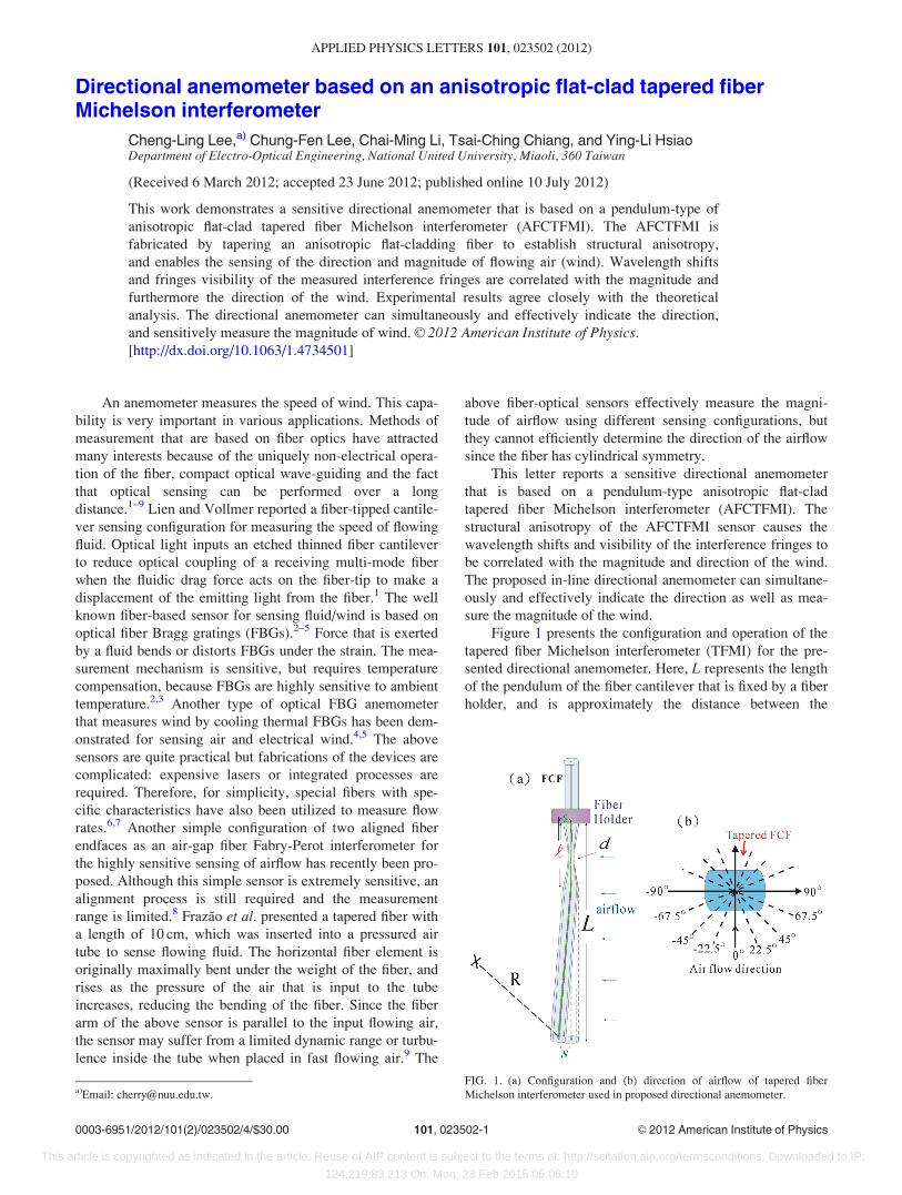
Figure 1 presents the configuration and operation of the
tapered fiber Michelson interferometer (TFMI) for the pre-
sented directional anemometer. Here, L represents the length
of the pendulum of the fiber cantilever that is fixed by a fiber
holder, and is approximately the distance between the
FIG. 1. (a) Configuration and (b) direction of airflow of tapered fiber
Michelson interferometer used in proposed directional anemometer.a)Email: [email protected].
0003-6951/2012/101(2)/023502/4/$30.00 VC 2012 American Institute of Physics101, 023502-1
APPLIED PHYSICS LETTERS 101, 023502 (2012)
This article is copyrighted as indicated in the article. Reuse of AIP content is subject to the terms at: http://scitation.aip.org/termsconditions. Downloaded to IP:
124.219.83.213 On: Mon, 23 Feb 2015 05:06:10
tapering point and the fiber endface; d is the tapering diame-
ter of fiber, and l is the length of the tapered region. As air
flows uniformly to the sensor in different directions, the
flowing fluid exerts a force on the fiber pendulum, bending
the pendulum and shifting the interference fringes. Figure
1(b) shows the direction of wind. When the airflow acts ver-
tically on the fiber cantilever, a force moment bends the fiber
cantilever and deflects the fiber tip with a transverse dis-
placement s. The magnitude of the torque that acts on the
fiber tip is proportional to s. The interference mechanism in
such TFMI has been demonstrated in Refs. 7, 9, and 10. In
the tapered section, light cannot be confined in the core
region and the light guidance will be controlled by the
cladding-air boundary thus high order cladding modes are
excited. When the light propagates into the non-tapered
region, the fundamental cladding mode will be transferred to
the fundamental core mode but the higher order cladding
modes remain in the cladding.11 These modes are reflected
by the fiber endface and interfered in the tapered region. In a
small bent angle, cladding mode coupling occurs mainly
between LP01 and LP0m in the original non-bending taper but
particularly between LP01 and LP1m in a bending condi-
tion.12 Thus, when the sensor is bent by an acting force, dif-
ferent coupled cladding modes would shift the interference
fringes and furthermore evanescent waves stretched much
into the air will make a higher loss of the sensor.
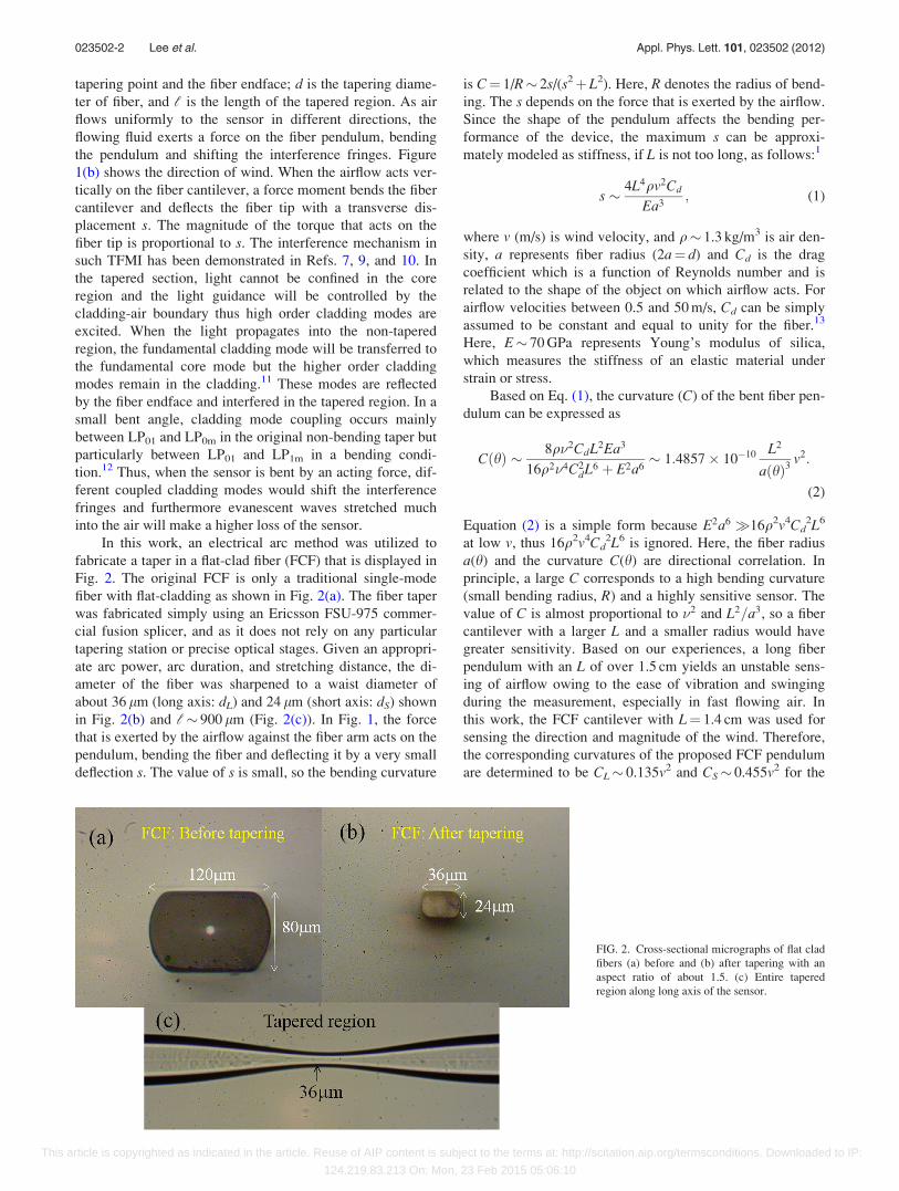
In this work, an electrical arc method was utilized to
fabricate a taper in a flat-clad fiber (FCF) that is displayed in
Fig. 2. The original FCF is only a traditional single-mode
fiber with flat-cladding as shown in Fig. 2(a). The fiber taper
was fabricated simply using an Ericsson FSU-975 commer-
cial fusion splicer, and as it does not rely on any particular
tapering station or precise optical stages. Given an appropri-
ate arc power, arc duration, and stretching distance, the di-
ameter of the fiber was sharpened to a waist diameter of
about 36 lm (long axis: dL) and 24 lm (short axis: dS) shown
in Fig. 2(b) and l� 900 lm (Fig. 2(c)). In Fig. 1, the force
that is exerted by the airflow against the fiber arm acts on the
pendulum, bending the fiber and deflecting it by a very small
deflection s. The value of s is small, so the bending curvature
is C¼ 1/R� 2s/(s2þL2). Here, R denotes the radius of bend-
ing. The s depends on the force that is exerted by the airflow.
Since the shape of the pendulum affects the bending per-
formance of the device, the maximum s can be approxi-
mately modeled as stiffness, if L is not too long, as follows:1
s � 4L4qv2Cd
Ea3; (1)
where v (m/s) is wind velocity, and q� 1.3 kg/m3 is air den-
sity, a represents fiber radius (2a¼ d) and Cd is the drag
coefficient which is a function of Reynolds number and is
related to the shape of the object on which airflow acts. For
airflow velocities between 0.5 and 50 m/s, Cd can be simply
assumed to be constant and equal to unity for the fiber.13
Here, E� 70 GPa represents Young’s modulus of silica,
which measures the stiffness of an elastic material under
strain or stress.
Based on Eq. (1), the curvature (C) of the bent fiber pen-
dulum can be expressed as
CðhÞ � 8q�2CdL2Ea3
16q2�4C2dL6 þ E2a6
� 1:4857� 10�10 L2
aðhÞ3v2:
(2)
Equation (2) is a simple form because E2a6 �16q2v4Cd2L6
at low v, thus 16q2v4Cd2L6 is ignored. Here, the fiber radius
a(h) and the curvature C(h) are directional correlation. In
principle, a large C corresponds to a high bending curvature
(small bending radius, R) and a highly sensitive sensor. The
value of C is almost proportional to �2 and L2=a3, so a fiber
cantilever with a larger L and a smaller radius would have
greater sensitivity. Based on our experiences, a long fiber
pendulum with an L of over 1.5 cm yields an unstable sens-
ing of airflow owing to the ease of vibration and swinging
during the measurement, especially in fast flowing air. In
this work, the FCF cantilever with L¼ 1.4 cm was used for
sensing the direction and magnitude of the wind. Therefore,
the corresponding curvatures of the proposed FCF pendulum
are determined to be CL� 0.135v2 and CS� 0.455v2 for the
FIG. 2. Cross-sectional micrographs of flat clad
fibers (a) before and (b) after tapering with an
aspect ratio of about 1.5. (c) Entire tapered
region along long axis of the sensor.
023502-2 Lee et al. Appl. Phys. Lett. 101, 023502 (2012)
This article is copyrighted as indicated in the article. Reuse of AIP content is subject to the terms at: http://scitation.aip.org/termsconditions. Downloaded to IP:
124.219.83.213 On: Mon, 23 Feb 2015 05:06:10
dL (long axis; at 690�) and dS (short axis; at 0�) axes on the
FCF cross section, respectively.
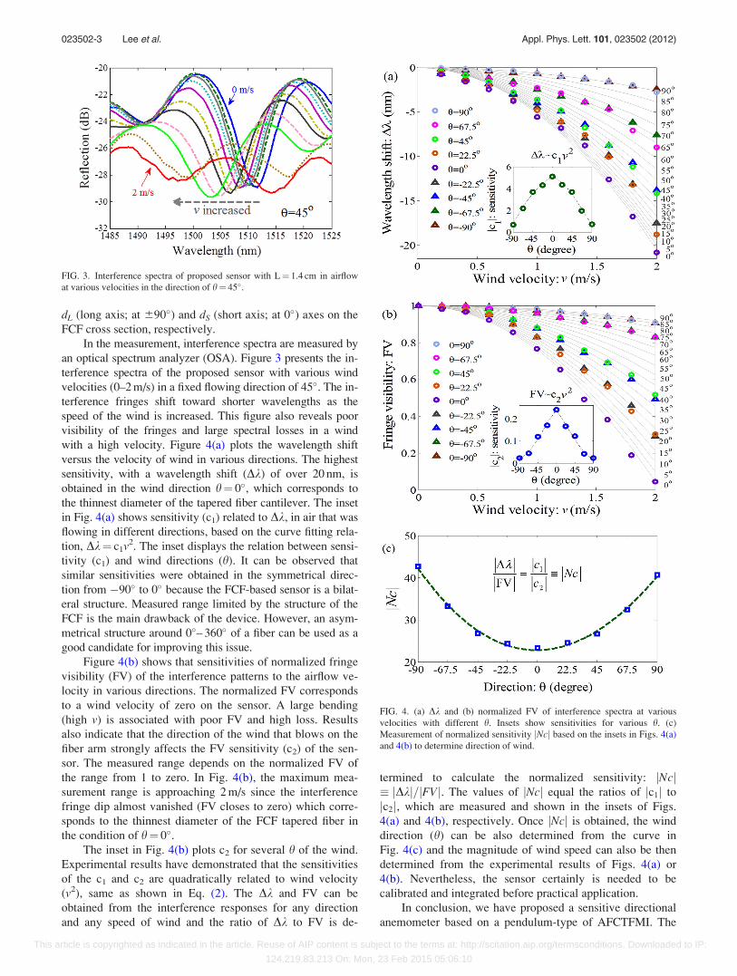
In the measurement, interference spectra are measured by
an optical spectrum analyzer (OSA). Figure 3 presents the in-
terference spectra of the proposed sensor with various wind
velocities (0–2 m/s) in a fixed flowing direction of 45�. The in-
terference fringes shift toward shorter wavelengths as the
speed of the wind is increased. This figure also reveals poor
visibility of the fringes and large spectral losses in a wind
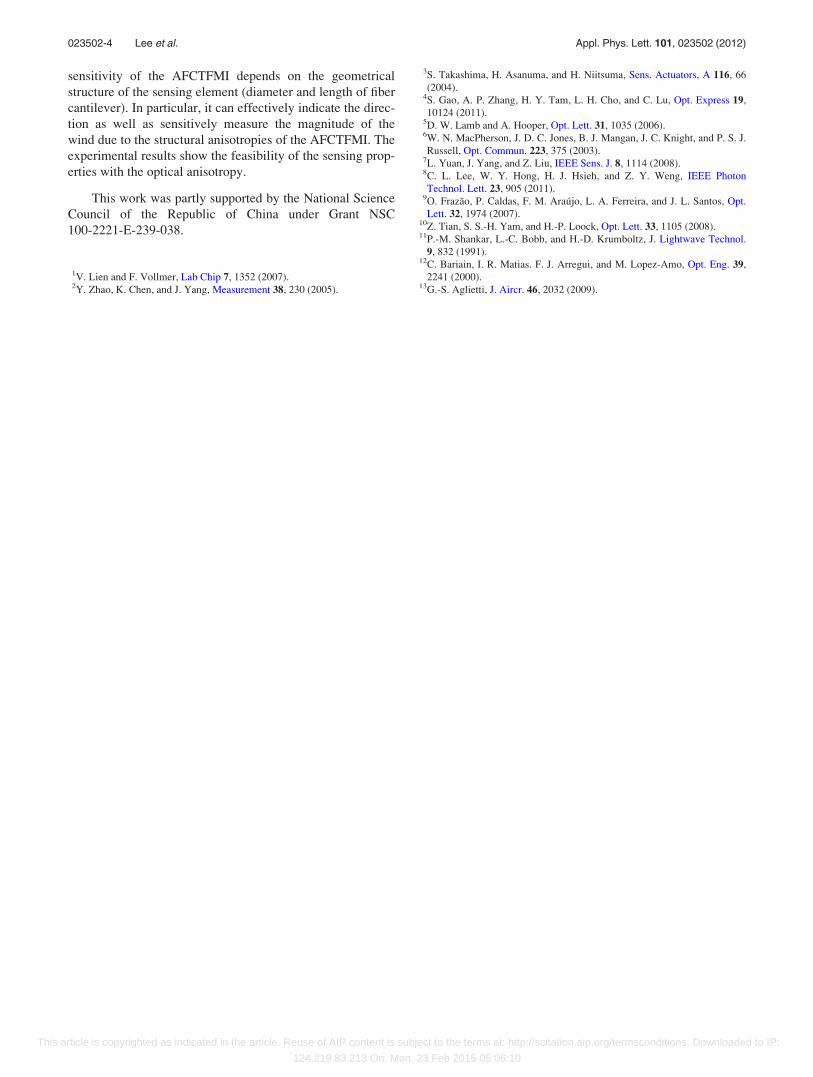
with a high velocity. Figure 4(a) plots the wavelength shift
versus the velocity of wind in various directions. The highest
sensitivity, with a wavelength shift (Dk) of over 20 nm, is
obtained in the wind direction h¼ 0�, which corresponds to
the thinnest diameter of the tapered fiber cantilever. The inset
in Fig. 4(a) shows sensitivity (c1) related to Dk, in air that was
flowing in different directions, based on the curve fitting rela-
tion, Dk¼ c1v2. The inset displays the relation between sensi-
tivity (c1) and wind directions (h). It can be observed that
similar sensitivities were obtained in the symmetrical direc-
tion from �90� to 0� because the FCF-based sensor is a bilat-
eral structure. Measured range limited by the structure of the
FCF is the main drawback of the device. However, an asym-
metrical structure around 0�– 360� of a fiber can be used as a
good candidate for improving this issue.
Figure 4(b) shows that sensitivities of normalized fringe
visibility (FV) of the interference patterns to the airflow ve-
locity in various directions. The normalized FV corresponds
to a wind velocity of zero on the sensor. A large bending
(high v) is associated with poor FV and high loss. Results
also indicate that the direction of the wind that blows on the
fiber arm strongly affects the FV sensitivity (c2) of the sen-
sor. The measured range depends on the normalized FV of
the range from 1 to zero. In Fig. 4(b), the maximum mea-
surement range is approaching 2 m/s since the interference
fringe dip almost vanished (FV closes to zero) which corre-
sponds to the thinnest diameter of the FCF tapered fiber in
the condition of h¼ 0�.The inset in Fig. 4(b) plots c2 for several h of the wind.
Experimental results have demonstrated that the sensitivities
of the c1 and c2 are quadratically related to wind velocity
(v2), same as shown in Eq. (2). The Dk and FV can be
obtained from the interference responses for any direction
and any speed of wind and the ratio of Dk to FV is de-
termined to calculate the normalized sensitivity: jNcj� jDkj=jFVj. The values of jNcj equal the ratios of jc1j to
jc2j, which are measured and shown in the insets of Figs.
4(a) and 4(b), respectively. Once jNcj is obtained, the wind
direction (h) can be also determined from the curve in
Fig. 4(c) and the magnitude of wind speed can also be then
determined from the experimental results of Figs. 4(a) or
4(b). Nevertheless, the sensor certainly is needed to be
calibrated and integrated before practical application.
In conclusion, we have proposed a sensitive directional
anemometer based on a pendulum-type of AFCTFMI. The
FIG. 3. Interference spectra of proposed sensor with L¼ 1.4 cm in airflow
at various velocities in the direction of h¼ 45�.
FIG. 4. (a) Dk and (b) normalized FV of interference spectra at various
velocities with different h. Insets show sensitivities for various h. (c)
Measurement of normalized sensitivity jNcj based on the insets in Figs. 4(a)
and 4(b) to determine direction of wind.
023502-3 Lee et al. Appl. Phys. Lett. 101, 023502 (2012)
This article is copyrighted as indicated in the article. Reuse of AIP content is subject to the terms at: http://scitation.aip.org/termsconditions. Downloaded to IP:
124.219.83.213 On: Mon, 23 Feb 2015 05:06:10
sensitivity of the AFCTFMI depends on the geometrical
structure of the sensing element (diameter and length of fiber
cantilever). In particular, it can effectively indicate the direc-
tion as well as sensitively measure the magnitude of the
wind due to the structural anisotropies of the AFCTFMI. The
experimental results show the feasibility of the sensing prop-
erties with the optical anisotropy.
This work was partly supported by the National Science
Council of the Republic of China under Grant NSC
100-2221-E-239-038.
1V. Lien and F. Vollmer, Lab Chip 7, 1352 (2007).2Y. Zhao, K. Chen, and J. Yang, Measurement 38, 230 (2005).
3S. Takashima, H. Asanuma, and H. Niitsuma, Sens. Actuators, A 116, 66
(2004).4S. Gao, A. P. Zhang, H. Y. Tam, L. H. Cho, and C. Lu, Opt. Express 19,
10124 (2011).5D. W. Lamb and A. Hooper, Opt. Lett. 31, 1035 (2006).6W. N. MacPherson, J. D. C. Jones, B. J. Mangan, J. C. Knight, and P. S. J.
Russell, Opt. Commun. 223, 375 (2003).7L. Yuan, J. Yang, and Z. Liu, IEEE Sens. J. 8, 1114 (2008).8C. L. Lee, W. Y. Hong, H. J. Hsieh, and Z. Y. Weng, IEEE Photon
Technol. Lett. 23, 905 (2011).9O. Frazao, P. Caldas, F. M. Araujo, L. A. Ferreira, and J. L. Santos, Opt.
Lett. 32, 1974 (2007).10Z. Tian, S. S.-H. Yam, and H.-P. Loock, Opt. Lett. 33, 1105 (2008).11P.-M. Shankar, L.-C. Bobb, and H.-D. Krumboltz, J. Lightwave Technol.
9, 832 (1991).12C. Bariain, I. R. Matias. F. J. Arregui, and M. Lopez-Amo, Opt. Eng. 39,
2241 (2000).13G.-S. Aglietti, J. Aircr. 46, 2032 (2009).
023502-4 Lee et al. Appl. Phys. Lett. 101, 023502 (2012)
This article is copyrighted as indicated in the article. Reuse of AIP content is subject to the terms at: http://scitation.aip.org/termsconditions. Downloaded to IP:
124.219.83.213 On: Mon, 23 Feb 2015 05:06:10