directional control valvesdocs-europe.electrocomponents.com/webdocs/0b79/09… · · 2014-11-2763...
TRANSCRIPT

Directionalcontrol ValvesG1/8, 3/2 and 5/2 Spool valves
Catalogue no: 2131GB-ca
Directional control valves G1/8 3/2 - 5/2
�
Spool valves 3/2, 5/2 - G1/8 Ports
Available in 3/2 or 5/2 versions, all valves includingdouble pilot and double solenoid types may bemounted in any position, The balanced spool designensures that operating forces remain unaffected byvariations in inlet pressure.
The body is a zinc alloy die-casting with stainless steelspool, sealed by viton rubber 'O' rings. All operatingparts exposed to the working fluid are of non-corrosivematerial and all ports are threaded G1/8 B.S.P. parallel.The block design of the body with its three mountingholes is ideally suited to close banking and all valvesmay be serviced without disturbing the pipeworksimply by unscrewing the actuator and returnassemblies.
The 3/2 valve can be piped normally open or closedsimply by changing the air inlet from the normal inletport to the exhaust port, and the 5/2 valve can bepiped in different variations to suit the applicationrequired. Midget spool valves can also be used asimpulse type valves, when the signal is required at theend of the cylinder stroke or when the tripping cylinderor machine cam is too small to clear the mechanicaltrip of the valve.
Operation of the actuator on the 5/2 valve opens thecylinder port nearest to the actuator. On the 3/2 versionthe inlet is piped to the port furthest away from theactuator for normally closed operation, and to the portnearest the actuator for normally open. Any of theactuators may be fitted with spring or pilot returnmechanism. Valves may also be supplied with thesame actuator at both ends; e.g. double roller. Rollerversions are designed to give a common height onboth 3/2 and 5/2 valves to ensure uniformity andefficiency in a multi-valve assembly.
The reasonably short travel and lightweight spoolensures that extremely high operating speeds arepossible. A double pilot 5/2 valve has been tested atover 3000 cycles per minute, but for practical purposesthe operating speed of the valve is determined bycylinder stroke and bore size.
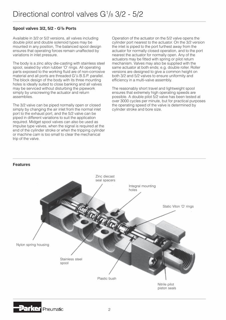
Features
Zinc diecastseal spacers
Integral mountingholes
Static Viton 'O' rings
Nylon spring housing
Stainless steelspool
Plastic bush
Nitrile pilotpiston seals

Directional control valves G1/8 3/2 - 5/2
�
Basic body dimensions (mm)
Actuator mechanisms Return mechanisms
Facia actuatorsØ22mm
ManualButtonLock down leverPalm leverFoot
MechanicalPlungerWhiskerRollerOne way tripOne way roller trip
Air pilot
Solenoid pilot
Optional foot mountingspring return housing
Standard springreturn housing
Basic bodies
3/2 body
5/2 body
Air pilothousing
33
48
16
33
63
16
16
32Ø15
27
15G1/8
48 61
13,5 16
6,5 5,5
1632
7,5
8
2323
8

Directional control valves G1/8 3/2 - 5/2
Solenoid pilot operated - spring return Symbol
Body Zinc diecast
Actuator Zinc diecast
Spool Stainless steel
Bushes Brass
Seals Viton (valve body)Nitrile (solenoid)
Spring housing Plastic
Materials
Pressure range Vacuum to 10 bar
Minimum Spring return 3 bar
Nominal Ø 3,2mm
Nominal flow at 7 bar 7 dm3/s
Cv factor 0,24
Pneumatic information
Type Spool valve
Style Body ported
Port size G1/8
Mounting Any plane
Temperature range -100C to +550C
Technical information
Part nos. Type Actuator Return Symbol
LB43313* 3/2 Solenoid pilot Spring
LB43314* 5/2 Solenoid pilot Spring
Ordering information
*Specify voltage and add suffix lettersFor manual override add suffix M to part no.
Power consumption Inrush Hold
AC 9VA 6VA
DC 5 Watt
Rating 100% continuous
Isolating class F
Protection class IP 65 (P 54) DIN 40 050
Connection ISO 4400, BS 56361
Electrical information Voltage selection
Suffix 50 Hz D.C.
T 10-13 5-6.5
TA 20-26 10-13
TF 44-55 20-26
TC 85-110 44-55
S 94-120 47-60
TS 153-198 76-99
SA 204-264 102-132
�
12
2
1 3
1014
2
315
12
4
Directional control valves G1/8 3/2 - 5/2
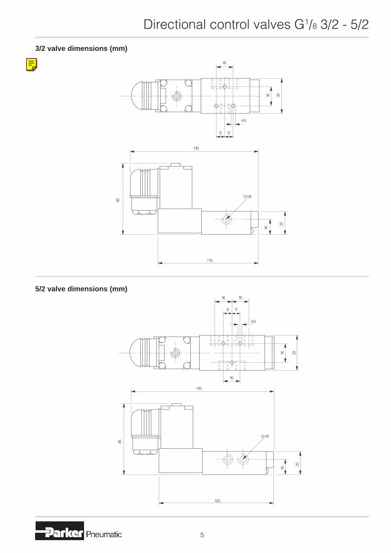
3/2 valve dimensions (mm)
5/2 valve dimensions (mm)
�
16
3316
8 8
4,8
130
65
G1/8
16
23
115
1616
88
4,8
16
3316
143
G1/8
65
100
23
16

Directional control valves G1/8 3/2 - 5/2
Solenoid pilot operated - pilot return Symbol
Body Aluminium
Actuator Zinc diecast
Spool Stainless steel
Bushes Brass
Seals Viton (valve body)Nitrile (solenoid)
Materials
Pressure range Vacuum to 10 bar
Minimum Spring return 3 bar
Nominal Ø 3,2mm
Nominal flow at 7 bar 7 dm3/s
Cv factor 0,24
Pneumatic information
Type Spool valve
Style Body ported
Port size G1/8
Mounting Any plane
Temperature range -100C to +550C
Technical information
Part nos. Type Actuator Return Symbol
LB43333* 3/2 Solenoid pilot Air pilot
LB43334* 5/2 Solenoid pilot Air pilot
Ordering information
*Specify voltage and add suffix lettersFor manual override add suffix M to part no.
Power consumption Inrush Hold
AC 9VA 6VA
DC 5 Watt
Rating 100% continuous
Isolating class F
Protection class IP 65 (P 54) DIN 40 050
Connection ISO 4400, BS 56361
Electrical information Voltage selection
Suffix 50 Hz D.C.
T 10-13 5-6.5
TA 20-26 10-13
TF 44-55 20-26
TC 85-110 44-55
S 94-120 47-60
TS 153-198 76-99
SA 204-264 102-132
�
12
210
14
2
3
12
4
1 3 15

Directional control valves G1/8 3/2 - 5/2
�
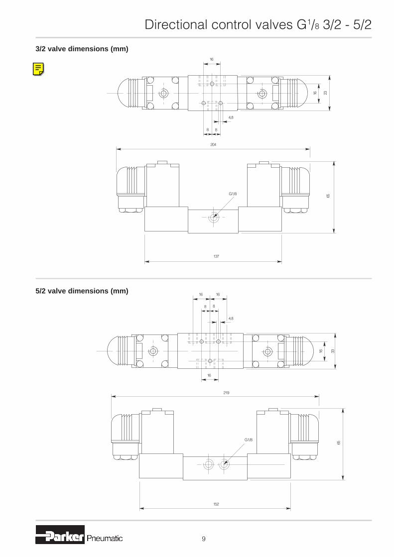
3/2 valve dimensions (mm)
5/2 valve dimensions (mm)
16
8 8
4,8
149
119
65
1616
88
4,8
16
173
135
231616
23
2316
G1/8G1/8
65
G1/8G1/8
23
16

Directional control valves G1/8 3/2 - 5/2
Double solenoid pilot operated valves Symbol
Body Zinc diecast
Actuator Zinc diecast
Spool Stainless steel
Bushes Brass
Seals Viton (valve body)Nitrile (solenoid)
Materials
Pressure range Vacuum to 10 bar
Minimum Spring return 3 bar
Nominal Ø 3,2mm
Nominal flow at 7 bar 7 dm3/s
Cv factor 0,24
Pneumatic information
Type Spool valve
Style Body ported
Port size G1/8
Mounting Any plane
Temperature range -100C to +550C
Technical information
Part nos. Type Actuator Return Symbol
LB43323* 3/2 Solenoid pilot Solenoid pilot
LB43324* 5/2 Solenoid pilot Solenoid pilot
Ordering information
*Specify voltage and add suffix lettersFor manual override add suffix M to part no.
Power consumption Inrush Hold
AC 9VA 6VA
DC 5 Watt
Rating 100% continuous
Isolating class F
Protection class IP 65 (P 54) DIN 40 050
Connection ISO 4400, BS 56361
Electrical information Voltage selection
Suffix 50 Hz D.C.
T 10-13 5-6.5
TA 20-26 10-13
TF 44-55 21-26
TC 85-110 43-55
S 94-121 54-69
TS 153-242 94-121
SA 204-264 102-132
�
12 1410 12
1 3 315
2 24
Directional control valves G1/8 3/2 - 5/2
3/2 valve dimensions (mm)
5/2 valve dimensions (mm)
�
1616
88
4,8
16
3316
219
G1/8
65
152
16
8 8
4,8
2316
65
G1/8
137
204
Information Bulletin
Product Group: Actuators Valves AirTreatment
FactoryAutomation
OtherProducts
Title: 150 Type Solenoid ActuatorsCatalogue: 2120GB, 2131GB, 2135GB, 2123GBDate of Issue: February 2000Bulletin No: IBL 10064
Action Required DistributionDiscard oldBulletin
Request newCatalogue
Add bulletinto Catalogue
ContactFactory
CheckStocks
1 2 3
Issued from the Marketing Department, Parker Pneumatic, Cannock – UKAny amendments or additions to be forwarded to the Marketing Department,
Fax No 00 44 (0)1543 456032
Template.doc Page 1
150 Type Solenoids Obsolete
Due to technical difficulties with supply of the 150 Type Low Profile Solenoids ithas become necessary to make them obsolete with immediate effect.This change will affect the following valve ranges: -ISO Size 1 ISO Size 2Midget G1/8 Spool Valves Intermediate G1/4 Spool valvesDirect Acting Solenoid Valves
It is planned to change all production on ISO Size 1 and ISO Size 2 immediately andto use the remaining stocks of 150s for the other ranges and progressively introducethe change during the next few months.
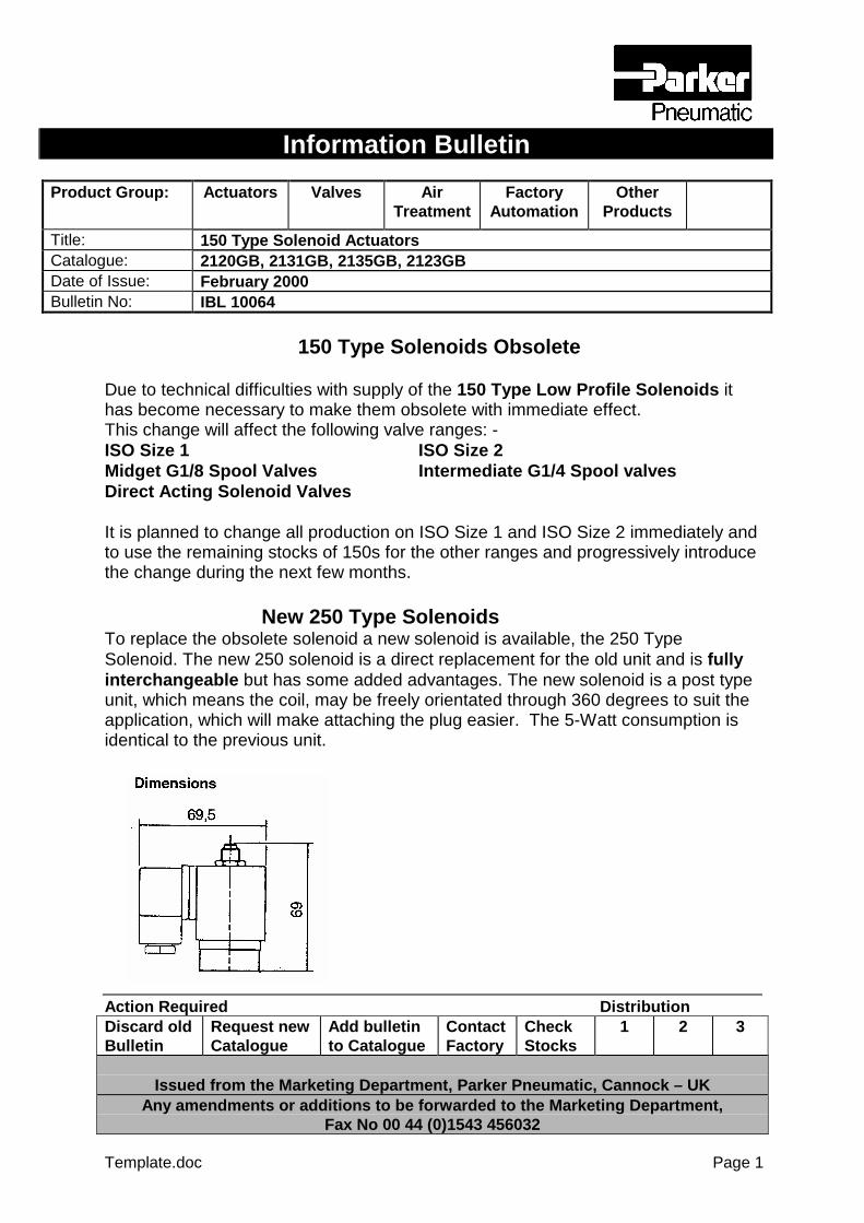
New 250 Type SolenoidsTo replace the obsolete solenoid a new solenoid is available, the 250 TypeSolenoid. The new 250 solenoid is a direct replacement for the old unit and is fullyinterchangeable but has some added advantages. The new solenoid is a post typeunit, which means the coil, may be freely orientated through 360 degrees to suit theapplication, which will make attaching the plug easier. The 5-Watt consumption isidentical to the previous unit.

Information Bulletin
Product Group: Actuators Valves AirTreatment
FactoryAutomation
OtherProducts
Title: 150 Type Solenoid ActuatorsCatalogue: 2120GB, 2131GB, 2135GB, 2123GBDate of Issue: February 2000Bulletin No: IBL 10064
Action Required DistributionDiscard oldBulletin
Request newCatalogue
Add bulletinto Catalogue
ContactFactory
CheckStocks
1 2 3
Issued from the Marketing Department, Parker Pneumatic, Cannock – UKAny amendments or additions to be forwarded to the Marketing Department,
Fax No 00 44 (0)1543 456032
Template.doc Page 2

Information Bulletin
Product Group: Actuators Valves AirTreatment
FactoryAutomation
OtherProducts
Title: 150 Series SolenoidsCatalogue:Date of Issue: June 2000Bulletin No: ILB 10065
Action Required DistributionDiscard oldBulletin
Request newCatalogue
Add bulletinto Catalogue
ContactFactory
CheckStocks
1 2 3
Issued from the Marketing Department, Parker Pneumatic, Cannock – UK
Page 1
‘150’ Series Solenoids
Further to Information Bulletin IBL10064, ‘150’ series solenoids are now obsolete and the followingvalves are now being supplied with new ‘250’ series coils:
‘Apollo’ Series ISO Valves ‘LB53’ Series Spool Valves
Size 1 Size 2 3 Port 5 Port
19114* 29114* LB53013* LB53014*
19114M* 29114M* LB53013M* LB53014M*
19124* 29124* LB53023* LB53024*
19124M* 29124M* LB53023M* LB53024M*
19124X* 29124MX* LB53033* LB53024X*
19124MX* 29124MX LB53033M* LB53024MX*
19124Y* 29124Y* LB53033J* LB53024Y*
19124MY* 29124MY* LB53024MY*
19124Z* 29124Z* LB53024Z*
19124MZ* 29124MZ* LB53024MZ*
19134* 29134* LB53034*
19134M* 29134M* LB53034M*
19134J* 29134J* LB53034J*
19134MJ* 29134MJ* LB53034MJ*
19134X* 29134X* LB53034X*
19134MX* 29134MX* LB53034MX*
19134Y* 29134Y* LB53034Y*
19134MY* 29134MY* LB53034MY*
19134Z* 29134Z* LB53034Z*
19134MZ* 29134MZ* LB53034M*
* Add voltage suffix letters, see note

Information Bulletin
Product Group: Actuators Valves AirTreatment
FactoryAutomation
OtherProducts
Title: 150 Series SolenoidsCatalogue:Date of Issue: June 2000Bulletin No: ILB 10065
Action Required DistributionDiscard oldBulletin
Request newCatalogue
Add bulletinto Catalogue
ContactFactory
CheckStocks
1 2 3
Issued from the Marketing Department, Parker Pneumatic, Cannock – UK
Page 2
The ‘Midget’ Series spool valves and solenoid Gang Manifolds will change to the new solenoid overthe next couple of months as stocks of ‘150’ series solenoids are used.The following valves will be effected by the change
Midget Spool Valves Midget Gang Manifold
LB43313* 33202*
LB43313M* 33202M*
LB43314* 33203*
LB43314M* 33203M*
LB43323* 33204*
LB43323M* 33204M*
LB43324* 33205*
LB43324M* 33205M*
LB43333* 33206*
LB43333M* 33206M*
LB43334* 33207*
LB43334M* 33207M*
33208*
33208M*
33209*
33209M*
33210*
33210M*
* Add voltage suffix letters, see note

Information Bulletin
Product Group: Actuators Valves AirTreatment
FactoryAutomation
OtherProducts
Title: 150 Series SolenoidsCatalogue:Date of Issue: June 2000Bulletin No: ILB 10065
Action Required DistributionDiscard oldBulletin
Request newCatalogue
Add bulletinto Catalogue
ContactFactory
CheckStocks
1 2 3
Issued from the Marketing Department, Parker Pneumatic, Cannock – UK
Page 3
The single stand-alone 3/2 direct acting Midget Solenoid Valve, 154*, will be replaced by a new valveon the 1st August 2000, Part Number, 254*
* Add voltage suffix letters, see note.
Voltage Suffix Letters
Since the initial introduction of the ‘150’ series solenoids, suffix letters have been used at the end ofthe Part Number to denote the required voltage range. The voltage ranges on the new ‘250’ seriescan in some cases replace two or more of the previously used ranges, see comparison chart shownbelow.
‘250’ Series Suffix letters Voltage Replaces ‘150’ Suffix letters
Replace ‘*’ with letters 50Hz.ac 60Hz.ac DC
‘S’ 110 110 ‘S’, ‘SC’, ‘TP’
‘T’ 12 12 ‘T’, ‘TE’
‘TA’ 24 24 ‘TA’, ‘TM’
‘TC’ 48 ‘TC’
‘TF’ 24 ‘TF’
‘TL’ 230 230 90 ‘TL’, ‘SA’, ‘TK’, ‘TS’, ‘TT’
Replacement Solenoids
Information Bulletin
Product Group: Actuators Valves AirTreatment
FactoryAutomation
OtherProducts
Title: 150 Series SolenoidsCatalogue:Date of Issue: June 2000Bulletin No: ILB 10065
Action Required DistributionDiscard oldBulletin
Request newCatalogue
Add bulletinto Catalogue
ContactFactory
CheckStocks
1 2 3
Issued from the Marketing Department, Parker Pneumatic, Cannock – UK
Page 4
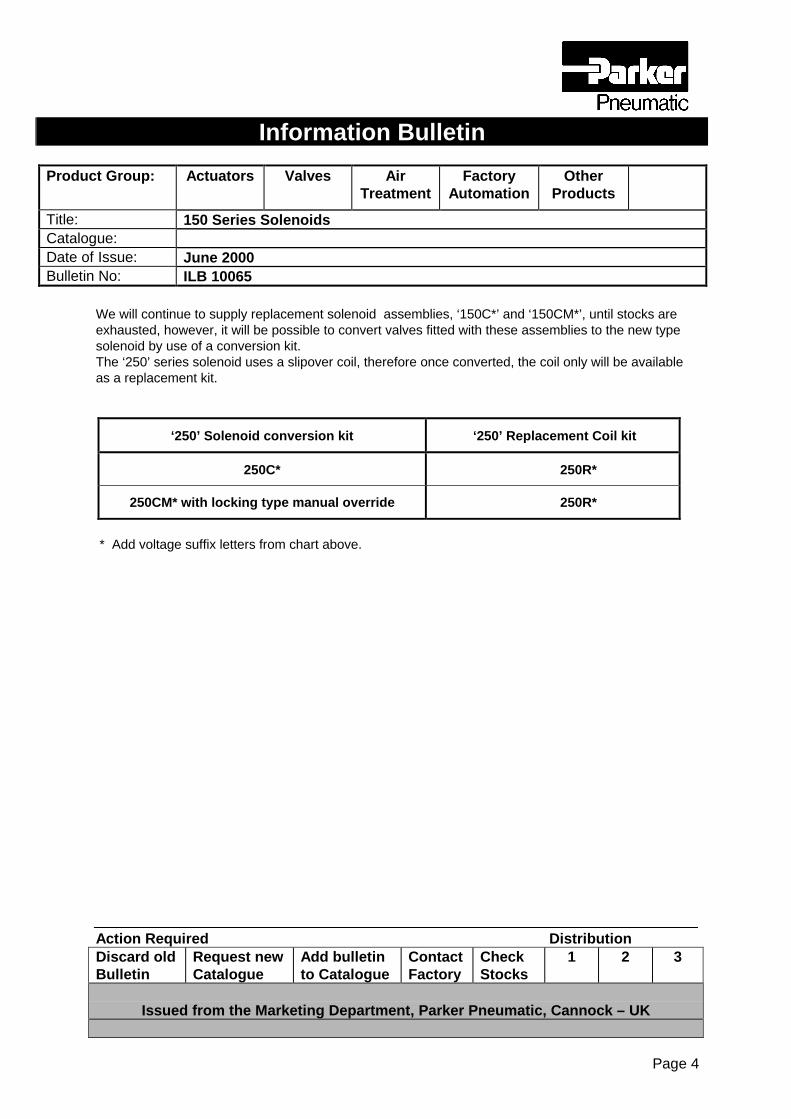
We will continue to supply replacement solenoid assemblies, ‘150C*’ and ‘150CM*’, until stocks areexhausted, however, it will be possible to convert valves fitted with these assemblies to the new typesolenoid by use of a conversion kit.The ‘250’ series solenoid uses a slipover coil, therefore once converted, the coil only will be availableas a replacement kit.
‘250’ Solenoid conversion kit ‘250’ Replacement Coil kit
250C* 250R*
250CM* with locking type manual override 250R*
* Add voltage suffix letters from chart above.

Information Bulletin
Product Group: Actuators Valves AirTreatment
FactoryAutomation
OtherProducts
Title: 3035 Series CNOMO SolenoidsCatalogue:Date of Issue: June 2000Bulletin No: IBL10066
Action Required DistributionDiscard oldBulletin
Request newCatalogue
Add bulletinto Catalogue
ContactFactory
CheckStocks
1 2 3
Issued from the Marketing Department, Parker Pneumatic, Cannock – UK
Page 1
‘3035’ Series ‘CNOMO’ SolenoidsFollowing the obsolescence of the ‘150’ series solenoid coil, it has become necessary to replace the‘3035’ series CNOMO solenoid with a new ‘350’ Series.As the ‘350’ series conform to the recognised ‘CNOMO’ standard they are directly interchangeablewith the ‘3035’ series. The following valves will now be fitted with the new ‘350 series coils :
‘Apollo’ Series ISO Valves with CNOMO coils
Size 1 Size 2 Size 3
19414* 29414* 39414*
19414M* 29414M* 39414M*
19414N* 29414N* 39414N*
19424* 29424* 39424*
19424M* 29424M* 39424M*
19424N* 29424N* 39424N*
19424X* 29424X* 39424X*
19424MX* 29424MX* 39424MX*
19424NX* 29424NX* 39424NX*
19424Y* 29424Y* 39424Y*
19424MY* 29424MY* 39424MY*
19424NY* 29424NY* 39424NY*
19424Z* 29424Z* 39424Z
19424MZ* 29424MZ* 39424MZ*
19424NZ* 29424NZ* 39424NZ*
19434* 29434* 39434*
19434M* 29434M* 39434M*
19434N* 29434N* 39434N*
19434J* 29434J* 39434J*
19434MJ* 29434MJ* 39434MJ*
19434NJ* 29434NJ* 39434NJ*
19434X* 29434X* 39434X*

Information Bulletin
Product Group: Actuators Valves AirTreatment
FactoryAutomation
OtherProducts
Title: 3035 Series CNOMO SolenoidsCatalogue:Date of Issue: June 2000Bulletin No: IBL10066
Action Required DistributionDiscard oldBulletin
Request newCatalogue
Add bulletinto Catalogue
ContactFactory
CheckStocks
1 2 3
Issued from the Marketing Department, Parker Pneumatic, Cannock – UK
Page 2
19434MX* 29434MX* 39434MX*
19434NX* 29434NX* 39434NX*
19434Y* 29434Y* 39434Y*
19434MY* 29434MY* 39434MY*
19434NY* 29434NY* 39434NY*
19434Z* 29434Z* 39434Z*
19434MZ* 29434MZ* 39434MZ*
19434NZ* 29434NZ* 39434NZ*
* Add voltage suffix letters, see noteM = Solenoid with locking manual overrideN = Solenoid with non locking manual override
Voltage Suffix Letters
Since the initial introduction of the ‘3035’ series solenoids, suffix letters have been used at the end ofthe Part Number to denote the required voltage range. The voltage ranges on the new ‘350’ seriescan in some cases replace two or more of the previously used ranges, see comparison chart shownbelow.
‘350’ Series Suffix letters Voltage Replaces ‘3035’ Suffix letters
Replace ‘*’ with letters 50Hz.ac 60Hz.ac DC
‘S’ 110 110 50 ‘S’, ‘SC’, ‘TP’
‘T’ 12 12 6 ‘T’, ‘TE’
‘TA’ 24 24 11 ‘TA’, ‘TM’
‘TF’ 48 48 24 ‘TF’
‘TL’ 230 230 120 ‘TL’ , ‘SA’, ‘TK’, ‘TT’
Replacement Solenoids
Information Bulletin
Product Group: Actuators Valves AirTreatment
FactoryAutomation
OtherProducts
Title: 3035 Series CNOMO SolenoidsCatalogue:Date of Issue: June 2000Bulletin No: IBL10066
Action Required DistributionDiscard oldBulletin
Request newCatalogue
Add bulletinto Catalogue
ContactFactory
CheckStocks
1 2 3
Issued from the Marketing Department, Parker Pneumatic, Cannock – UK
Page 3
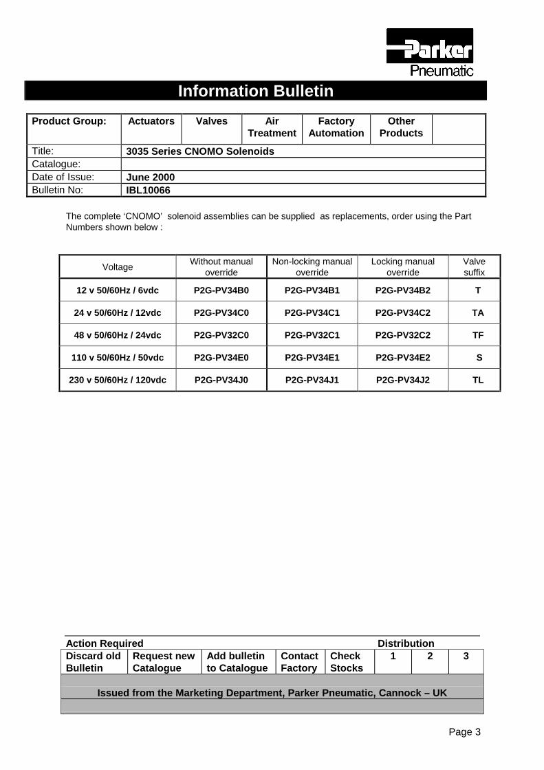
The complete ‘CNOMO’ solenoid assemblies can be supplied as replacements, order using the PartNumbers shown below :
VoltageWithout manual
overrideNon-locking manual
overrideLocking manual
overrideValvesuffix
12 v 50/60Hz / 6vdc P2G-PV34B0 P2G-PV34B1 P2G-PV34B2 T
24 v 50/60Hz / 12vdc P2G-PV34C0 P2G-PV34C1 P2G-PV34C2 TA
48 v 50/60Hz / 24vdc P2G-PV32C0 P2G-PV32C1 P2G-PV32C2 TF
110 v 50/60Hz / 50vdc P2G-PV34E0 P2G-PV34E1 P2G-PV34E2 S
230 v 50/60Hz / 120vdc P2G-PV34J0 P2G-PV34J1 P2G-PV34J2 TL
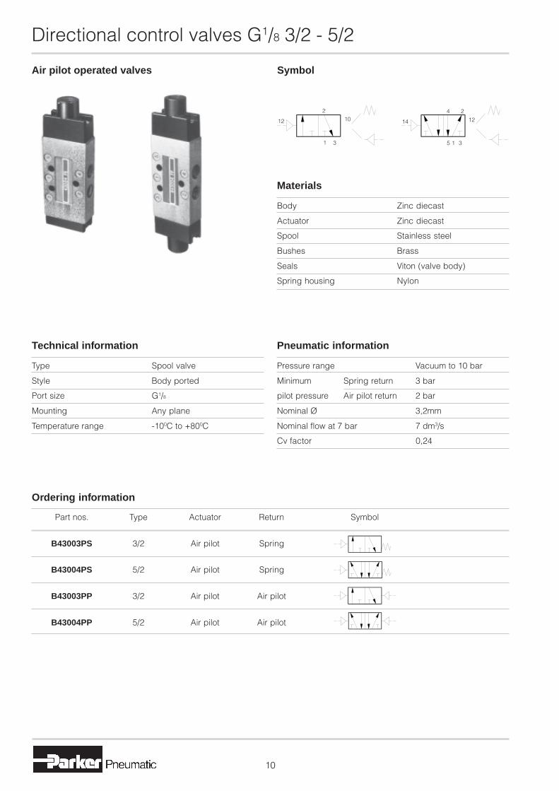
Directional control valves G1/8 3/2 - 5/2
Air pilot operated valves Symbol
Body Zinc diecast
Actuator Zinc diecast
Spool Stainless steel
Bushes Brass
Seals Viton (valve body)
Spring housing Nylon
Materials
Pressure range Vacuum to 10 bar
Minimum Spring return 3 bar
pilot pressure Air pilot return 2 bar
Nominal Ø 3,2mm
Nominal flow at 7 bar 7 dm3/s
Cv factor 0,24
Pneumatic information
Type Spool valve
Style Body ported
Port size G1/8
Mounting Any plane
Temperature range -100C to +800C
Technical information
Part nos. Type Actuator Return Symbol
B43003PS 3/2 Air pilot Spring
B43004PS 5/2 Air pilot Spring
B43003PP 3/2 Air pilot Air pilot
B43004PP 5/2 Air pilot Air pilot
Ordering information
12
2
1 3
10 14
5 1 3
12
4 2

Directional control valves G1/8 3/2 - 5/2
3/2 valve dimensions (mm)
Air pilot operatedspring return
Air pilot operatedAir pilot return
5/2 valve dimensions (mm)
Air pilot operatedspring return
Air pilot operatedAir pilot return
16G1/8
12
G1/8
88
32
19
33
83
4,8
33
G1/8
1639
G1/8
102
39
98
G1/8
16
G1/8
12
88
1616
4,8
39
19
33
47
118 G1/8
4716
G1/8
33

Directional control valves G1/8 3/2 - 5/2
�
Diaphragm operated valves Symbol
Body Zinc diecast
Actuator Zinc diecast
Spool Stainless steel
Bushes Brass
Seals Viton
Spring housing Zinc diecast
Diaphragm Nitrile
Materials
Pressure range Vacuum to 10 bar
Minimum Spring return 0,3 bar
pilot pressure Diaphragm return 0,13 bar
Nominal Ø 3,2mm
Nominal flow at 7 bar 7 dm3/s
Cv factor 0,24
Pneumatic information
Type Spool valve
Style Body ported
Port size G1/8
Mounting Any plane
Temperature range -100C to +800C
Technical information
Part nos. Type Actuator Return Symbol
B43003DF 3/2 Diaphragm Spring
B43004DF 5/2 Diaphragm Spring
B43003DD 3/2 Diaphragm Diaphragm
B43004DD 5/2 Diaphragm Diaphragm
B43004D-50 Mounting bracket kit
Ordering information
Comprises: 1 bracket, 3 bolts and nuts
12
2
31
1014
4 2
5 1 3
12

Directional control valves G1/8 3/2 - 5/2
�
3/2 valve dimensions (mm)
Diaphragm operatedspring return
Diaphragm operatedDiaphragm return
5/2 valve dimensions (mm)
Diaphragm operatedspring return
Diaphragm operatedDiaphragm return
Mounting brackets
Ø89
G1/8
103
8
G1/
8
8
4,8
6,519
33
48
G1/
8
38
Ø89
Ø20
G1/8
Ø20
G1/
8
35,5
35,5
G1/
8G1/8
103
Ø89
G1/8
4,8
1616
88
119
6,5
G1/8
AA
48
33
19
4,8
Ø20
G1/8
Ø89
G1/
8
42,5
42,5
G1/
8
146
Ø20
G1/8
7 x holes
4635
51
38
70
77

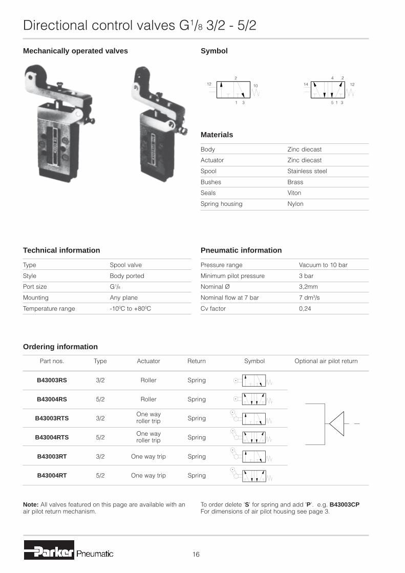
Directional control valves G1/8 3/2 - 5/2
�
Mechanically operated valves Symbol
Body Zinc diecast
Actuator Zinc diecast
Spool Stainless steel
Bushes Brass
Seals Viton
Spring housing Nylon
Materials
Pressure range Vacuum to 10 bar
Minimum pilot pressure 3 bar
Nominal Ø 3,2mm
Nominal flow at 7 bar 7 dm3/s
Cv factor 0,24
Pneumatic information
Type Spool valve
Style Body ported
Port size G1/8
Mounting Any plane
Temperature range -100C to +800C
Technical information
Part nos. Type Actuator Return Symbol Optional air pilot return
B43003CS 3/2 Plunger Spring
B43004CS 5/2 Plunger Spring
B43003W 3/2 Spring
B43004WO 5/2 Spring
B43004W 5/2 Whisker Spring
Ordering information
Whiskernormally closed
Whiskernormally open
Note: All valves featured on this page are available with anair pilot return mechanism.
To order delete 'S' for spring and add 'P'. e.g. B43003CPFor dimensions of air pilot housing see page 3.
122
10 14
4 2
12
1 3 35 1

Directional control valves G1/8 3/2 - 5/2
�
3/2 valve dimensions (mm)
Plunger operatedspring return
Whisker operatedspring return
5/2 valve dimensions (mm)
Plunger operatedspring return
Whisker operatedspring return
22,3
G1/8
16
Ø16
Ø6
0,5
4,5
Actuated
Full stroke
4
716
86
4,8
88
32
33
19
8218
154
3315
23
4,8
16
22,3
Ø16
Ø6
0,5
4,5
4 Actuated
Full stroke
G1/8
88
39
19
33
1616
102
167
23
171
1882
33
Directional control valves G1/8 3/2 - 5/2
�
Mechanically operated valves Symbol
Body Zinc diecast
Actuator Zinc diecast
Spool Stainless steel
Bushes Brass
Seals Viton
Spring housing Nylon
Materials
Pressure range Vacuum to 10 bar
Minimum pilot pressure 3 bar
Nominal Ø 3,2mm
Nominal flow at 7 bar 7 dm3/s
Cv factor 0,24
Pneumatic information
Type Spool valve
Style Body ported
Port size G1/8
Mounting Any plane
Temperature range -100C to +800C
Technical information
Note: All valves featured on this page are available with anair pilot return mechanism.
To order delete 'S' for spring and add 'P'. e.g. B43003CPFor dimensions of air pilot housing see page 3.
Part nos. Type Actuator Return Symbol Optional air pilot return
B43003RS 3/2 Roller Spring
B43004RS 5/2 Roller Spring
B43003RTS 3/2 Spring
B43004RTS 5/2 Spring
B43003RT 3/2 One way trip Spring
B43004RT 5/2 One way trip Spring
Ordering information
One wayroller trip
One wayroller trip
122
1 3
10 14
4 2
12
35 1
Directional control valves G1/8 3/2 - 5/2
�
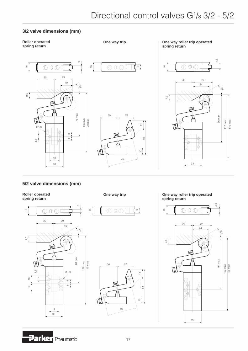
3/2 valve dimensions (mm)
Roller operatedspring return
5/2 valve dimensions (mm)
One way roller trip operatedspring return
One way trip
Roller operatedspring return
One way roller trip operatedspring return
One way trip
16
6
16 9
30 29
19
300
106
max
99 m
ax75 m
ax
G1/8
88
4,8
19
33
9,5
30 27
1158
10
48
16
4,5
30 27
24
7,5
300
86 m
ax
110
max
117
max
33
300
115
max
G1/84,8
16
30 29
6
16 9
19
83 m
ax
122
max
9,5
1616
88
19
33
30 27
1158
10
48
94 m
ax
16
4,5
30 27
24
7,5
300
133
max
126
max
33

Directional control valves G1/8 3/2 - 5/2
�
Manually operated valves Symbol
Body Zinc diecast
Actuator Zinc diecast
Spool Stainless steel
Bushes Brass
Seals Viton
Spring housing Nylon
Materials
Pressure range Vacuum to 10 bar
Minimum pilot pressure 3 bar
Nominal Ø 3,2mm
Nominal flow at 7 bar 7 dm3/s
Cv factor 0,24
Pneumatic information
Type Spool valve
Style Body ported
Port size G1/8
Mounting Any plane
Temperature range -100C to +550C
Technical information
Part nos. Type Actuator Return Symbol Optional air pilot return
B43003BS 3/2 Button Spring
B43004BS 5/2 Button Spring
B43003HS 3/2 Button Button
B43004HS 5/2 Button Button
B43003LS 3/2 Lock down lever Spring
B43004LS 5/2 Lock down lever Spring
Ordering information
Note: All valves featured on this page are available with anair pilot return mechanism.
To order delete 'S' for spring and add 'P'. e.g. B43003CPFor dimensions of air pilot housing see page 3.
122
10 14
4 2
12
1 3 35 1
Directional control valves G1/8 3/2 - 5/2
�
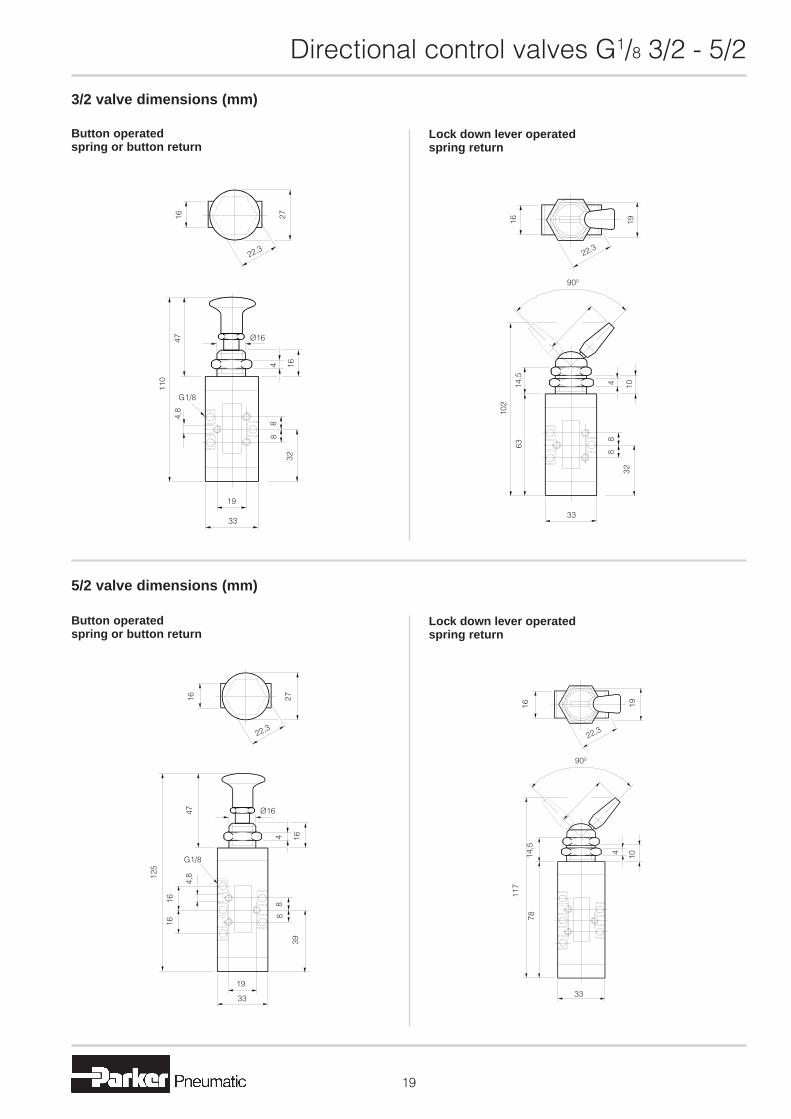
3/2 valve dimensions (mm)
Button operatedspring or button return
Lock down lever operatedspring return
5/2 valve dimensions (mm)
Button operatedspring or button return
Lock down lever operatedspring return
22,3
4,8
G1/8
16 27
Ø16
4 16
47
110
88
32
19
33
4
G1/8
4,8
16
22,3
27
Ø1647
16
125
1616
88
39
19
33
16
22,3
19
900
30
414,5
10
102
63
88
32
3316
22,3
19
900
30
10414,5
117
78
33

Directional control valves G1/8 3/2 - 5/2
�
Manually operated valves Symbol
Body Zinc diecast
Actuator Zinc diecast
Spool Stainless steel
Bushes Brass
Seals Viton
Spring housing Nylon
Materials
Pressure range Vacuum to 10 bar
Minimum pilot pressure 3 bar
Nominal Ø 3,2mm
Nominal flow at 7 bar 7 dm3/s
Cv factor 0,24
Pneumatic information
Type Spool valve
Style Body ported
Port size G1/8
Mounting Any plane
Temperature range -100C to +550C
Technical information
Part nos. Type Actuator Return Symbol Optional air pilot return
B43003ES 3/2 Palm lever Spring
B43004ES 5/2 Palm lever Spring
B43003FS 3/2 Foot pedal Spring
B43004FS 5/2 Foot pedal Spring
Ordering information
Note: All valves featured on this page are available with anair pilot return mechanism.
To order delete 'S' for spring and add 'P'. e.g. B43003CPFor dimensions of air pilot housing see page 3.
122
10 14
4 2
12
1 3 35 1
Directional control valves G1/8 3/2 - 5/2
�
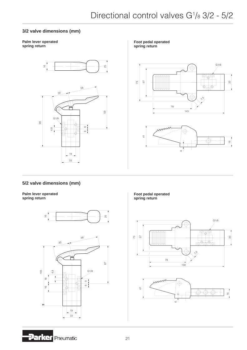
3/2 valve dimensions (mm)
Palm lever operatedspring return
Foot pedal operatedspring return
5/2 valve dimensions (mm)
Palm lever operatedspring return
Foot pedal operatedspring return
16 25
56
30
4,8
90
G1/8
88
59
19
33
73 57
G1/8
33
7,5
143
78
41
6
16
73 57
G1/8
33
7,5
78
158
41
6
16
16 25
30
56
105
4,8
1616
88
G1/8
67
19
33
Directional control valves G1/8 3/2 - 5/2
��
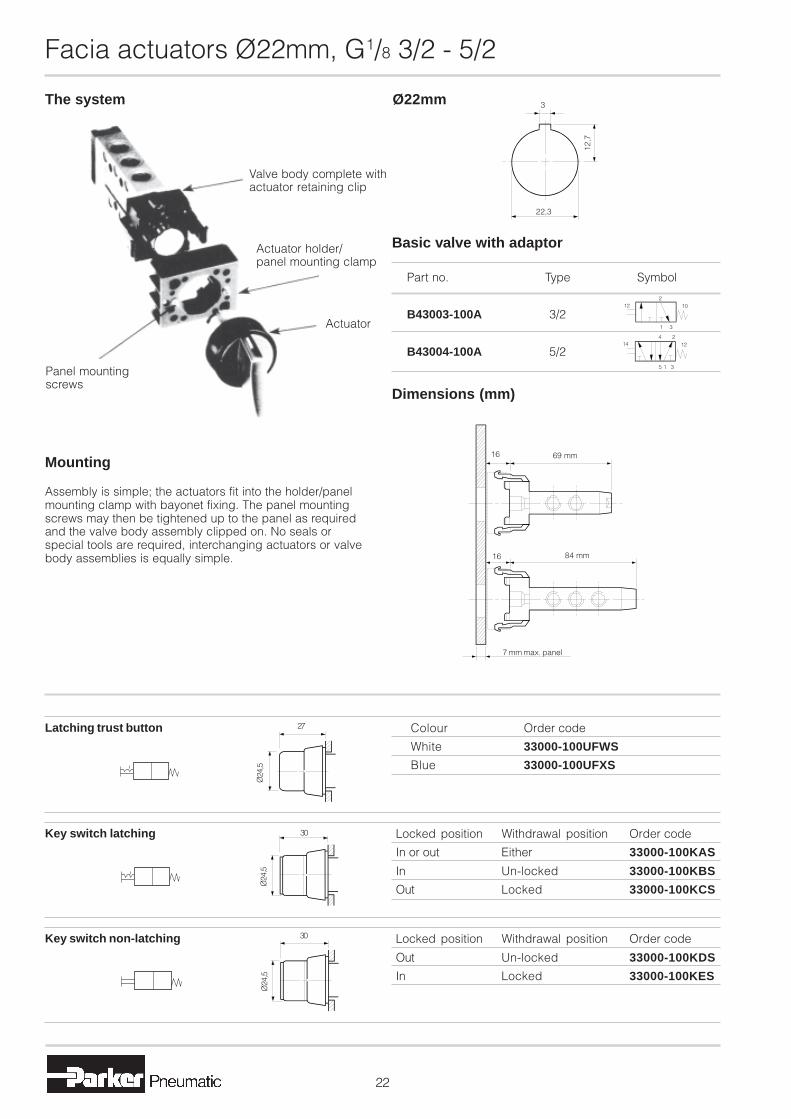
Facia actuators Ø22mm, G1/8 3/2 - 5/2
The system
Panel mountingscrews
Valve body complete withactuator retaining clip
Actuator holder/panel mounting clamp
Actuator
Mounting
Assembly is simple; the actuators fit into the holder/panelmounting clamp with bayonet fixing. The panel mountingscrews may then be tightened up to the panel as requiredand the valve body assembly clipped on. No seals orspecial tools are required, interchanging actuators or valvebody assemblies is equally simple.
Ø22mm
Locked position Withdrawal position Order code
Out Un-locked 33000-100KDS
In Locked 33000-100KES
Key switch non-latching 30
Ø24
,5
22,3
12,7
3
Part no. Type Symbol
B43003-100A 3/2
B43004-100A 5/2
Basic valve with adaptor
2
31
1012
14 1224
315
Dimensions (mm)
Locked position Withdrawal position Order code
In or out Either 33000-100KAS
In Un-locked 33000-100KBS
Out Locked 33000-100KCS
Key switch latching
Ø24
,5
30
Colour Order code
White 33000-100UFWS
Blue 33000-100UFXS
Latching trust button 27
Ø24
,5
84 mm
69 mm16
16
7 mm max. panel

Directional control valves G1/8 3/2 - 5/2
��
Colour Order code
White 33000-100UAWS
Black 33000-100UAXS
Red 33000-100UAYS
Green 33000-100UAZS
Latching selector knob 27
12
27
Colour Order code
Yellow 33000-100BCTS
Blue 33000-100BCUS
White 33000-100BCWS
Black 33000-100BCXS
Red 33000-100BCYS
Green 33000-100BCZS
Push button with boot
Ø29
,5
12
Colour Order code
Yellow 33000-100BBTS
Blue 33000-100BBUS
Black 33000-100BBXS
Red 33000-100BBYS
Raised push button 15
Ø24
,5
Colour Order code Type
Red 33000-100BEYS Ø40 Mushroom, key release
Red 33000-100BGYS Ø40 Mushroom latching
Red 33000-100BPYS Raised latching button
Red 33000-100BRYS Ø70 Mushroom latching
Emergency button 30
Ø70
41
Ø40
Withdrawl position Order code
Either 33000-100KFS
Key switch 'stay-put' 12
12
27
Colour Order code
Yellow 33000-100BATS
Blue 33000-100BAUS
White 33000-100BAWS
Black 33000-100BAXS
Red 33000-100BAYS
Green 33000-100BAZS
Flush push button12
Ø29
,5
Colour Order code
White 33000-100UBWS
Black 33000-100UBXS
Red 33000-100UBYS
Green 33000-100UBZS
Non latching selector knob 27
27
Colour Order code
White 33000-100BDTS
Black 33000-100BDXS
Red 33000-100BDYS
Green 33000-100BDZS
Ø30mm Mushroom button 28
Ø30
12

Directionalcontrol ValvesG1/4, 3/2, 5/2, 3/3 and 5/3Spool valves
Catalogue no. 2135GB-caEdition: September 2007

2
3/2, 5/2, 3/3, 5/3 Spool Valves G1/4 Ports
This quality and proven range of valves feature a block formzinc diecast body passivated to prevent corrosion anddesigned to allow complete interchangeability of actuatorsand return mechanisms. The stainless steel spool is sealedby synthetic viton 'O' rings, with unique seal spacers toensure full air flow through the open ports. Non corrosivematerials are used on all operating parts exposed to theworking fluid.
Individual valves may be mounted in any position, the blockform construction in particularly convenient for compactbanking. Valves may be serviced in-situ by removal of theactuator, facilitating extraction of the spool and 'O' rings.
Tell-tale indicators on both solenoid and pilot operatedvalves can be used to check the position of the main spoolor as a manual over-ride.
Operation of the actuator on the 5/2 valve opens the cylinderport nearest to the actuator. On the 3/2 version the inlet ispiped to the port furthest away from the actuator for normallyclosed operation, and to the port nearest the actuator fornormally open. Any of the actuators may be fitted with springor pilot return mechanism. Valves may also be supplied withthe same actuator at both ends; e.g. double roller. Rollerversions are designed to give a common height on both 3/2and 5/2 valves to ensure uniformity and efficiency in a multi-valve assembly.
Centre position valves; either spring to centre or3-position (detented mid-position) are available in thefollowing configurations:
Neutral X - Spool in mid-position - all ports closed.
Negative Y - Spool in mid-position - Cylinder ports open toexhaust, inlet closed.
Positive Z - Spool in mid-position - both cylinder ports opento inlet, exhaust closed.
Features
Integral mountingholes
Optional inlinepilot port
Tell tale indicator/manual override
StaticViton 'O' ring
Brassseal spacers
Lightweight stainlesssteel spool
Directional control valves G1/4
FAILURE OR IMPROPER SELECTION OR IMPROPER USE OF THE PRODUCTS AND/OR SYSTEMS DESCRIBED HEREIN OR RELATED ITEMS CAN CAUSE DEATH, PERSONAL INJURY ANDPROPERTY DAMAGE.This document and other information from Parker Hannifin Corporation, its subsidiaries and authorized distributors provide product and/or system options for further investigation by users having technicalexpertise. It is important that you analyze all aspects of your application and review the information concerning the product or system in the current product catalog. Due to the variety of operating conditionsand applications for these products or systems, the user, through its own analysis and testing, is solely responsible for making the final selection of the products and systems and assuring that all performance,safety and warning requirements of the application are met. The products described herein, including without limitation, product features, specifications, designs, availability and pricing, are subject to changeby Parker Hannifin Corporation and its subsidiaries at any time without notice.
WARNING
SALE CONDITIONSThe items described in this document are available for sale by Parker Hannifin Corporation, its subsidiaries or its authorized distributors. Any sale contract entered into by Parker will be governed bythe provisions stated in Parker’s standard terms and conditions of sale (copy available upon request).

3
Basic body dimensions (mm)
Actuator mechanisms Return mechanisms
3/2 body
Basic bodies
5/2 body
3/3 body
5/3 body
MechanicalPlunger
ManualButtonFootLever
Air pilot
Solenoid pilot
Directional control valves G1/4
Standard springreturn housing
Air pilot housing
41
4227
64
2742
2742
41 26
42
2664
27
11
4227
18
34
G1/8
G1/8
42
11
33
27
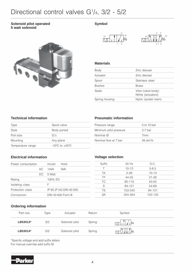
Solenoid pilot operated5 watt solenoid
Symbol
Body Zinc diecast
Actuator Zinc diecast
Spool Stainless steel
Bushes Brass
Seals Viton (valve body)Nitrile (actuators)
Spring housing Nylon (acetal resin)
Materials
Pressure range 0 to 10 bar
Minimum pilot pressure 2,7 bar
Nominal Ø 7mm
Nominal flow at 7 bar 26 dm3/s
Pneumatic information
Type Spool valve
Style Body ported
Port size G1/4
Mounting Any plane
Temperature range -100C to +550C
Technical information
Part nos. Type Actuator Return Symbol
LB53013* 3/2 Solenoid pilot Spring
LB53014* 5/2 Solenoid pilot Spring
Ordering information
*Specify voltage and add suffix lettersFor manual override add suffix M.
Power consumption Inrush Hold
AC 14VA 9VA
DC 5 Watt
Rating 100% ED
Isolating class F
Protection class IP 65 (P 54) DIN 40 050
Connection DIN 43 650 Form B
Electrical information Voltage selection
Suffix 50 Hz D.C.
T 10-13 5-6.5
TA 2-26 10-13
TF 44-55 21-26
TC 85-110 43-55
S 94-121 54-69
TS 153-242 94-121
SA 204-264 102-132
4
12 14 12
Directional control valves G1/4, 3/2 - 5/2
3
210
1 315
4 2

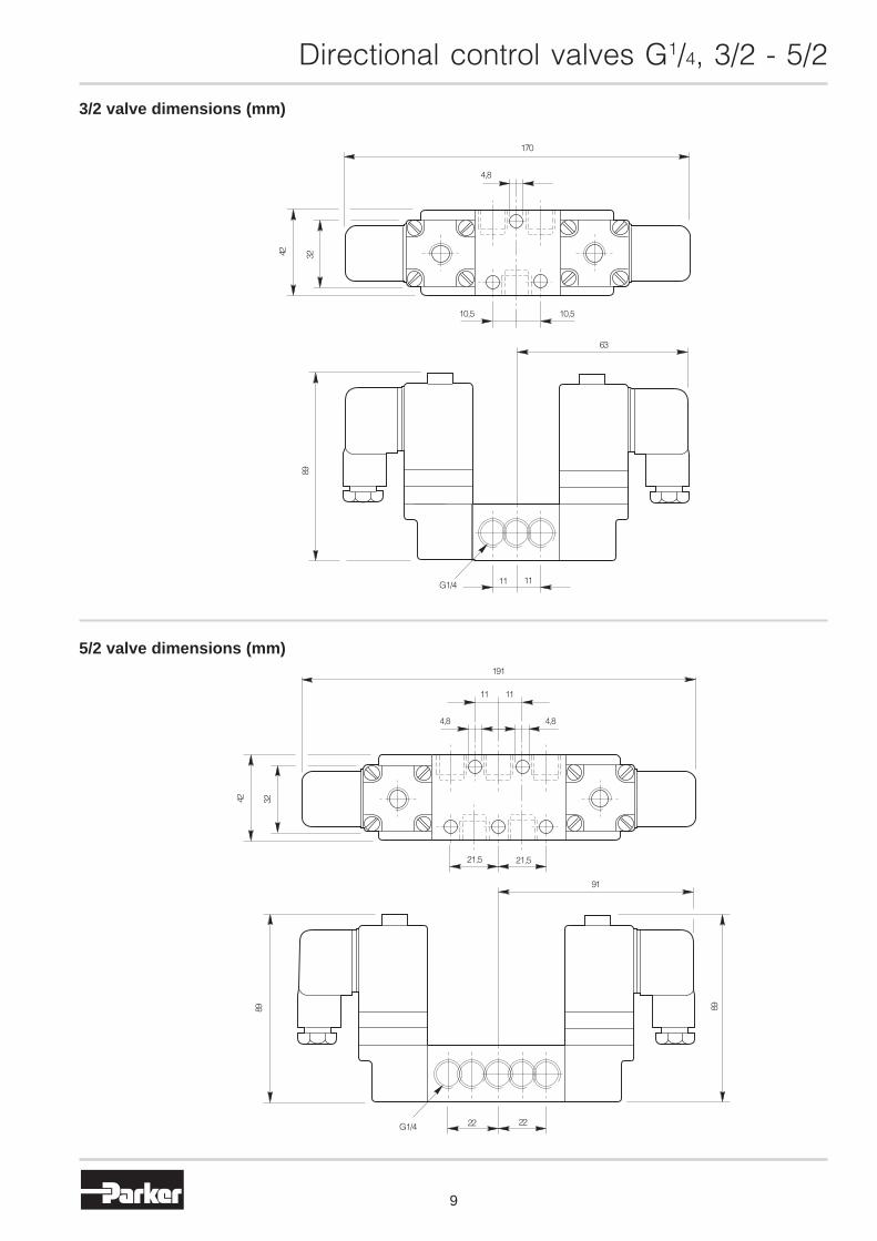
3/2 valve dimensions (mm)
5/2 valve dimensions (mm)
5
Directional control valves G1/4, 3/2 - 5/2
4,8
3242
10,5 10,5
89
31,5
27
G1/411 11
116
4,8
11 11
42 32
21,5 21,5
42
27
G1/4 2222
137
89

Solenoid pilot operated5 watt solenoid
Symbol
Body Aluminium
Actuator Zinc diecast
Spool Stainless steel
Bushes Brass
Seals Viton (valve body)Nitrile (actuators)
Materials
Pressure range 0 to10 bar
Minimum pilot pressure 2,7 bar
Nominal Ø 7mm
Nominal flow at 7 bar 26 dm3/s
Pneumatic information
Type Spool valve
Style Body ported
Port size G1/4
Mounting Any plane
Temperature range -100C to +550C
Technical information
Part nos. Type Actuator Return Symbol
LB53033* 3/2 Solenoid pilot Air pilot
LB53034* 5/2 Solenoid pilot Air pilot
Ordering information
*Specify voltage and add suffix lettersFor manual override add suffix M.
Power consumption Inrush Hold
AC 14VA 9VA
DC 5 Watt
Rating 100% ED
Isolating class F
Protection class IP 65 (P 54) DIN 40 050
Connection DIN 43 650 Form B
Electrical information Voltage selection
Suffix 50 Hz D.C.
T 10-13 5-6.5
TA 2-26 10-13
TF 44-55 21-26
TC 85-110 43-55
S 94-121 54-69
TS 153-242 94-121
SA 204-264 102-132
6
12 14
2
12
4
5
Directional control valves G1/4, 3/2 - 5/2
1 3
102
1 3

7
3/2 valve dimensions (mm)
5/2 valve dimensions (mm)
Directional control valves G1/4, 3/2 - 5/2
3242
4,8
10,5 10,5
52
89
27
1111G1/4
135
11 11
4,8
42 32
21,5 21,5
64
85
157
2222G1/4
27

Solenoid pilot operated5 watt solenoid
Symbol
Body Zinc diecast
Actuator Zinc diecast
Spool Stainless steel
Bushes Brass
Seals Viton (valve body)Nitrile (actuators)
Materials
Pressure range 0 to10 bar
Minimum Spring return 2,7 bar
Nominal Ø 7mm
Nominal flow at 7 bar 26 dm3/s
Pneumatic information
Type Spool valve
Style Body ported
Port size G1/4
Mounting Any plane
Temperature range -100C to +550C
Technical information
Part nos. Type Actuator Return Symbol
LB53033* 3/2 Solenoid pilot Air pilot
LB53034* 5/2 Solenoid pilot Air pilot
Ordering information
*Specify voltage and add suffix lettersFor manual override add suffix M.
Power consumption Inrush Hold
AC 14VA 9VA
DC 5 Watt
Rating 100% ED
Isolating class F
Protection class IP 65 (P 54) DIN 40 050
Connection DIN 43 650 Form B
Electrical information Voltage selection
Suffix 50 Hz D.C.
T 10-13 5-6.5
TA 2-26 10-13
TF 44-55 21-26
TC 85-110 43-55
S 94-121 54-69
TS 153-242 94-121
SA 204-264 102-132
8
12 1410 12
315
24
Directional control valves G1/4, 3/2 - 5/2
2
1 3
3/2 valve dimensions (mm)
5/2 valve dimensions (mm)
9
Directional control valves G1/4, 3/2 - 5/2
4,8
170
3242
10,510,5
63
89
G1/4 11 11
11 11
4,8 4,8
191
42 32
21,5 21,5
91
8989
2222G1/4
10
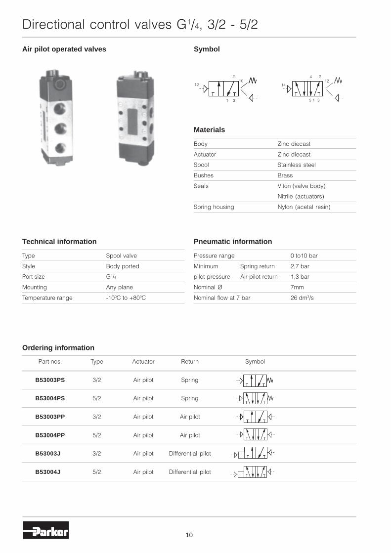
Air pilot operated valves Symbol
Body Zinc diecast
Actuator Zinc diecast
Spool Stainless steel
Bushes Brass
Seals Viton (valve body)
Nitrile (actuators)
Spring housing Nylon (acetal resin)
Materials
Pressure range 0 to10 bar
Minimum Spring return 2,7 bar
pilot pressure Air pilot return 1,3 bar
Nominal Ø 7mm
Nominal flow at 7 bar 26 dm3/s
Pneumatic information
Type Spool valve
Style Body ported
Port size G1/4
Mounting Any plane
Temperature range -100C to +800C
Technical information
Part nos. Type Actuator Return Symbol
B53003PS 3/2 Air pilot Spring
B53004PS 5/2 Air pilot Spring
B53003PP 3/2 Air pilot Air pilot
B53004PP 5/2 Air pilot Air pilot
B53003J 3/2 Air pilot Differential pilot
B53004J 5/2 Air pilot Differential pilot
Ordering information
12 14
Directional control valves G1/4, 3/2 - 5/2
1024
5 1 3
122
1 3

11
3/2 valve dimensions (mm)
Air pilot operatedspring return
Double air pilot operated
5/2 valve dimensions (mm)
Air pilot operatedspring return
Double air pilot operated
Directional control valves G1/4, 3/2 - 5/2
27
10
G1/8
42
32
10,5
10,5
85
G1/4
4,8
318
1
10
27
G1/8
42
1
108
10,5
10,5
4,8
G1/4
8
32
42
32
8
1
G1/4
130
21,5
21,5
4,8
1111
27
10
G1/8
8
1
G1/4
107
21,5
21,5
10
42
32
4,842
1111
G1/8
27

12
Mechanically operated valves Symbol
Part nos. Type Actuator Return Symbol Optional air pilot return
B53003CS 3/2 Plunger Spring
B53004CS 5/2 Plunger Spring
B53003RS 3/2 Roller Spring
B53004RS 5/2 Roller Spring
Ordering information
Directional control valves G1/4, 3/2 - 5/2
Body Zinc diecast
Actuator Zinc diecast
Spool Stainless steel
Bushes Brass
Seals Viton (valve body)
Nitrile (actuators)
Spring housing Nylon (acetal resin)
Materials
Pressure range 0 to10 bar
Nominal Ø 7mm
Nominal flow at 7 bar 26 dm3/s
Pneumatic information
Type Spool valve
Style Body ported
Port size G1/4
Mounting Any plane
Temperature range -100C to +800C
Technical information
Note: All valves featured on this page are available with airpilot return mechanisms. To order delete 'S' for spring andadd 'P' e.g. B53003CP.
For dimensions of air pilot housing see page
31
210
12
5 1 3
4 21214
13
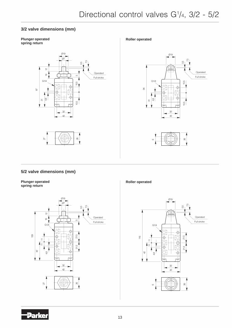
3/2 valve dimensions (mm)
Plunger operatedspring return
Roller operated
5/2 valve dimensions (mm)
Plunger operatedspring return
Directional control valves G1/4, 3/2 - 5/2
Roller operated
G1/4
1612
87
4,8
31
42
32
10,5
10,5
5
0,5 7,
5
Ø7
Ø19
Operated
Full stroke2627
Ø19
Ø7
Operated
Full stroke
7,5
0,5
521
,521
,5
42
32
4,842
1111
109
G1/4
1216
27 26
Ø19
7,5
0,5
Full stroke
Operated
21,5
21,5
G1/4
4,8
1111
42
116
42
32
266
Ø19
0,5 7,
5
Full stroke
Operated
10,5
10,5
42
32
2664,
8
31
G1/4
94
14
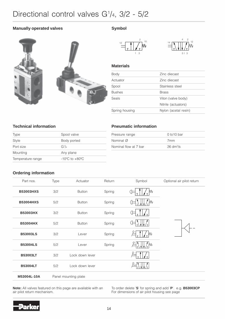
Manually operated valves Symbol
Directional control valves G1/4, 3/2 - 5/2
Note: All valves featured on this page are available with anair pilot return mechanism.
To order delete 'S' for spring and add 'P'. e.g. B53003CPFor dimensions of air pilot housing see page
Body Zinc diecast
Actuator Zinc diecast
Spool Stainless steel
Bushes Brass
Seals Viton (valve body)
Nitrile (actuators)
Spring housing Nylon (acetal resin)
Materials
Part nos. Type Actuator Return Symbol Optional air pilot return
B53003HXS 3/2 Button Spring
B53004HXS 5/2 Button Spring
B53003HX 3/2 Button Spring
B53004HX 5/2 Button Spring
B53003LS 3/2 Lever Spring
B53004LS 5/2 Lever Spring
B53003LT 3/2 Lock down lever
B53004LT 5/2 Lock down lever
M53004L-10A Panel mounting plate
Ordering information
Pressure range 0 to10 bar
Nominal Ø 7mm
Nominal flow at 7 bar 26 dm3/s
Pneumatic information
Type Spool valve
Style Body ported
Port size G1/4
Mounting Any plane
Temperature range -100C to +800C
Technical information
31
210
12
5 1 3
4 21214

15
3/2 valve dimensions (mm)
Button operatedspring return
Lever operatedspring return
Directional control valves G1/4, 3/2 - 5/2
Button operatedspring return
Lever operatedspring return
5/2 valve dimensions (mm)
Panel mounting
Ø27
Ø19
5
4216
G1/410
,510
,54,8
31
111
32
42
2627
133
Ø27
Ø194216 5
G1/4
21,5
21,5
4,8
32
42
42
1111
262734o
100
G1/4
27
82
314,8
14
54 45 4232
10,510,5M5
100
34o
G1/4
27
104
14
42
4,8
11 11
4232
M5
54 45
21,521,5
Mounting plate max. 6mm
Mounting panel max. 3mm
16
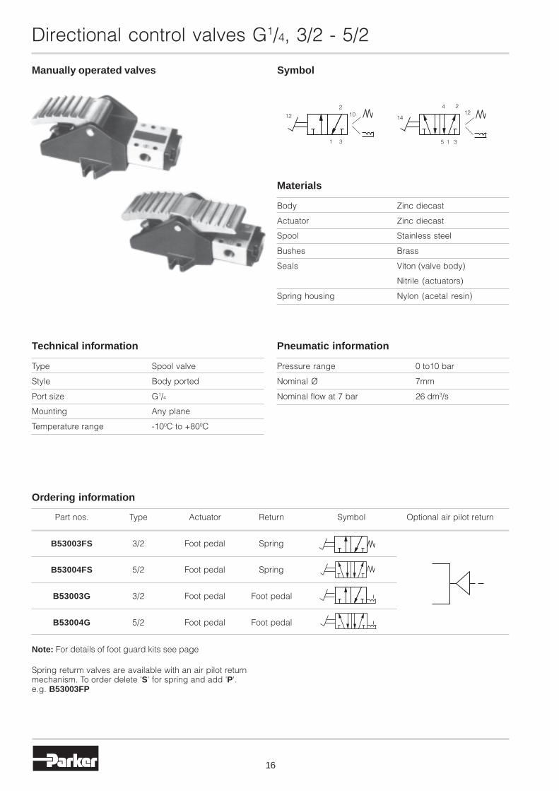
Manually operated valves Symbol
12
Directional control valves G1/4, 3/2 - 5/2
Body Zinc diecast
Actuator Zinc diecast
Spool Stainless steel
Bushes Brass
Seals Viton (valve body)
Nitrile (actuators)
Spring housing Nylon (acetal resin)
Materials
Part nos. Type Actuator Return Symbol Optional air pilot return
B53003FS 3/2 Foot pedal Spring
B53004FS 5/2 Foot pedal Spring
B53003G 3/2 Foot pedal Foot pedal
B53004G 5/2 Foot pedal Foot pedal
Ordering information
Note: For details of foot guard kits see page
Spring returm valves are available with an air pilot returnmechanism. To order delete 'S' for spring and add 'P'.e.g. B53003FP
Pressure range 0 to10 bar
Nominal Ø 7mm
Nominal flow at 7 bar 26 dm3/s
Pneumatic information
Type Spool valve
Style Body ported
Port size G1/4
Mounting Any plane
Temperature range -100C to +800C
Technical information
1 3
210
14
35 1
4 212

17
Directional control valves G1/4, 3/2 - 5/2
3/2 valve dimensions (mm)
Foot pedal operatedspring return
Foot pedal operated
5/2 valve dimensions (mm)
Foot pedal operatedspring return
Foot pedal operated
62
10
G1/4
27
66
314,8
164
94232
10,510,5
3889 76
72
10
66
27
G1/4
140
9
164
4,831
10,5 10,5 4,832 423889 76
164
140
G1/4
72
10
88
27
4,8
42
11 11
4232
21,521,5
9
387689
623889 76
10
G1/4
27
88
186
9 42
4,8
11 11
4232
21,521,5

18
Directional control valves G1/4, - 5/3
Double solenoid pilot operated5 watt solenoidSelf centring valves
Symbol
Body Zinc diecast
Actuator Zinc diecast
Spool Stainless steel
Bushes Brass
Seals Viton (valve body)Nitrile (actuators)
Materials
Pressure range 0 to10 bar
Minimum Spring return 1,7 bar
Nominal Ø 7mm
Nominal flow at 7 bar 26 dm3/s
Pneumatic information
Type Spool valve
Style Body ported
Port size G1/4
Mounting Any plane
Temperature range -100C to +550C
Technical information
Power consumption Inrush Hold
AC 14VA 9VA
DC 5 Watt
Rating 100% ED
Isolating class F
Protection class IP 65 (P 54) DIN 40 050
Connection DIN 43 650 Form B
Electrical information Voltage selection
Suffix 50 Hz D.C.
T 10-13 5-6.5
TA 2-26 10-13
TF 44-55 21-26
TC 85-110 43-55
S 94-121 54-69
TS 153-242 94-121
SA 204-264 102-132
Part nos. Type Actuator Return Mid Symbol
LB53024X* 5/3 Solenoid pilot Solenoid pilot Neutral
LB53024Y* 5/3 Solenoid pilot Solenoid pilot Negative
LB53024Z* 5/3 Solenoid pilot Solenoid pilot Positive
Ordering information
*Specify voltage and add suffix lettersFor manual override add suffix M.
315
24
14 12

19
5/3 valve dimensions (mm)
Directional control valves G1/4, - 5/3
42 32
4,8
11 11
217
21,5 21,5
91
2222G1/4
89
20
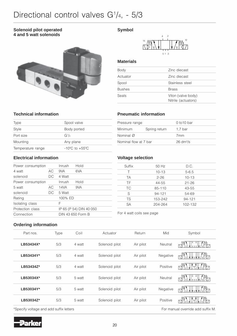
Directional control valves G1/4, - 5/3
Solenoid pilot operated4 and 5 watt solenoids
Symbol
Body Zinc diecast
Actuator Zinc diecast
Spool Stainless steel
Bushes Brass
Seals Viton (valve body)Nitrile (actuators)
Materials
Pressure range 0 to10 bar
Minimum Spring return 1,7 bar
Nominal Ø 7mm
Nominal flow at 7 bar 26 dm3/s
Pneumatic information
Type Spool valve
Style Body ported
Port size G1/4
Mounting Any plane
Temperature range -100C to +550C
Technical information
Power consumption Inrush Hold
4 watt AC 9VA 6VA
solenoid DC 4 Watt
Power consumption Inrush Hold
5 watt AC 14VA 9VA
solenoid DC 5 Watt
Rating 100% ED
Isolating class F
Protection class IP 65 (P 54) DIN 40 050
Connection DIN 43 650 Form B
Electrical information Voltage selection
Suffix 50 Hz D.C.
T 10-13 5-6.5
TA 2-26 10-13
TF 44-55 21-26
TC 85-110 43-55
S 94-121 54-69
TS 153-242 94-121
SA 204-264 102-132
Part nos. Type Coil Actuator Return Mid Symbol
LB53434X* 5/3 4 watt Solenoid pilot Air pilot Neutral
LB53434Y* 5/3 4 watt Solenoid pilot Air pilot Negative
LB53434Z* 5/3 4 watt Solenoid pilot Air pilot Positive
LB53034X* 5/3 5 watt Solenoid pilot Air pilot Neutral
LB53034Y* 5/3 5 watt Solenoid pilot Air pilot Negative
LB53034Z* 5/3 5 watt Solenoid pilot Air pilot Positive
Ordering information
*Specify voltage and add suffix letters For manual override add suffix M.
For 4 watt coils see page
315
24
14 12
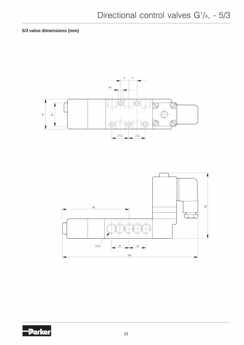
21
5/3 valve dimensions (mm)
Directional control valves G1/4, - 5/3
42 32
183
2222G1/4
89 89
21,521,5
1111
4,8
Directional control valves G1/4, - 5/3
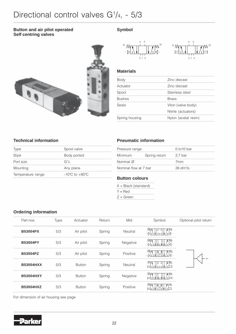
Button and air pilot operatedSelf centring valves
Symbol
Body Zinc diecast
Actuator Zinc diecast
Spool Stainless steel
Bushes Brass
Seals Viton (valve body)
Nitrile (actuators)
Spring housing Nylon (acetal resin)
Materials
Part nos. Type Actuator Return Mid Symbol Optional pilot return
B53004PX 5/3 Air pilot Spring Neutral
B53004PY 5/3 Air pilot Spring Negative
B53004PZ 5/3 Air pilot Spring Positive
B53004HXX 5/3 Button Spring Neutral
B53004HXY 5/3 Button Spring Negative
B53004HXZ 5/3 Button Spring Positive
Ordering information
For dimension of air housing see page
Pressure range 0 to10 bar
Minimum Spring return 2,7 bar
Nominal Ø 7mm
Nominal flow at 7 bar 26 dm3/s
Pneumatic information
Type Spool valve
Style Body ported
Port size G1/4
Mounting Any plane
Temperature range -100C to +800C
Technical information
X = Black (standard)
Y = Red
Z = Green
Button colours
22
12
315 315
4 214 12
4 214
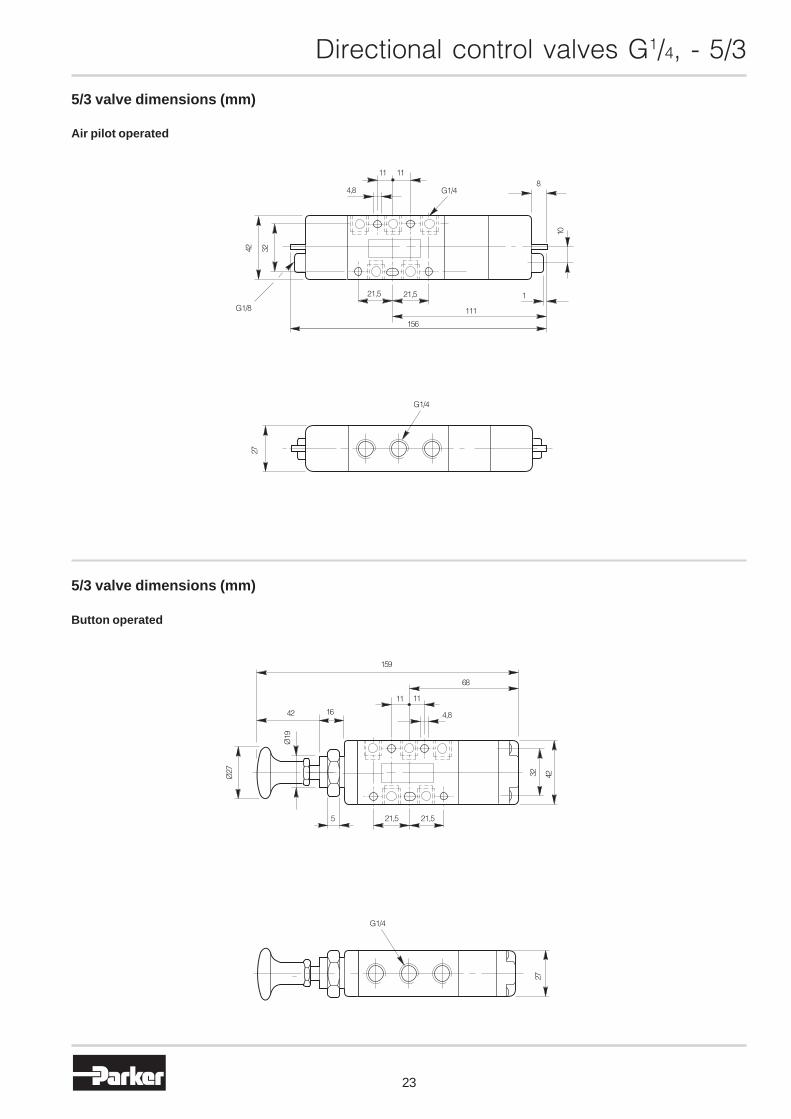
Directional control valves G1/4, - 5/3
5/3 valve dimensions (mm)
Air pilot operated
5/3 valve dimensions (mm)
Button operated
23
42 32
4,8
G1/8
27
G1/4
156
111
121,521,5
11 11
G1/48
10
159
1111
4,8
68
1642
21,5 21,55
Ø27
Ø19
32 42
G1/4
27

Directional control valves G1/4, 3/3 - 5/3
24
Lever operatedSelf centring valves
Symbol
Part nos. Type Actuator Return Mid Symbol Optional air pilot return
B53003LX 3/3 Lever Spring Neutral
B53004LX 5/3 Lever Spring Neutral
B53004LY 5/3 Lever Spring Negative
B53004LZ 5/3 Lever Spring Positive
M53004L-10A Panel mounting plate
Ordering information
Pressure range 0 to10 bar
Nominal Ø 7mm
Nominal flow at 7 bar 26 dm3/s
Pneumatic information
Type Spool valve
Style Body ported
Port size G1/4
Mounting Any plane
Temperature range -200C to +800C
Technical information
Body Zinc diecast
Actuator Zinc diecast
Spool Stainless steel
Bushes Brass
Seals Viton (valve body)
Nitrile (actuators)
Spring housing Nylon (acetal resin)
Materials
3 1
21012 14
5 1 3
124 2

Directional control valves G1/4, 3/3 - 5/3
25
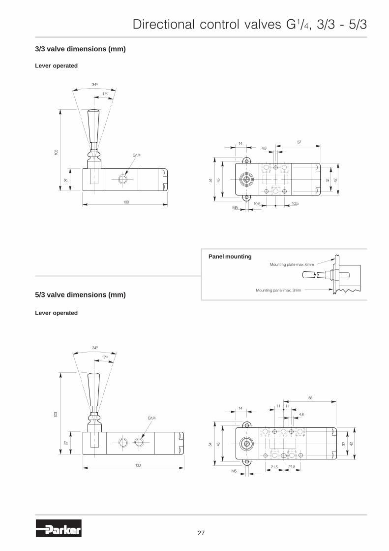
3/3 valve dimensions (mm)
Lever operated
Lever operated
5/3 valve dimensions (mm)
Panel mountingMounting plate max. 6mm
Mounting panel max. 3mm
G1/4
34O
17O
103
27
108
144,8
57
4232
10,510,5M5
4554
34O
17O
103
27
G1/4
130M5
21,5 21,5
4554
14 11 11
68
4,8
4232

Directional control valves G1/4, 3/3 - 5/3
26
Lever operated3 position
Symbol
12
Part nos. Type Actuator Return Mid Symbol Optional air pilot return
B53003L 3/3 Lever Lever Neutral
B53004L 5/3 Lever Lever Neutral
B53003LW 5/3 Lever Lever Negative
B53004LN 5/3 Lever Lever Positive
M53004L-10A Panel mounting plate
Ordering information
Pressure range 0 to10 bar
Nominal Ø 7mm
Nominal flow at 7 bar 26 dm3/s
Pneumatic information
Type Spool valve
Style Body ported
Port size G1/4
Mounting Any plane
Temperature range -200C to +800C
Technical information
Body Zinc diecast
Actuator Zinc diecast
Spool Stainless steel
Bushes Brass
Seals Viton (valve body)
Nitrile (actuators)
Spring housing Nylon (acetal resin)
Materials
14
1 3
10
2 4 2
15 3
12
Directional control valves G1/4, 3/3 - 5/3
27
3/3 valve dimensions (mm)
Lever operated
Lever operated
5/3 valve dimensions (mm)
Panel mountingMounting plate max. 6mm
Mounting panel max. 3mm
G1/4
34O
17O
103
27
108
144,8
57
4232
10,510,5M5
4554
34O
17O
103
27
G1/4
130M5
21,5 21,5
4554
14 11 11
68
4,8
4232
Directional control valves G1/4, 3/3 - 5/3
28
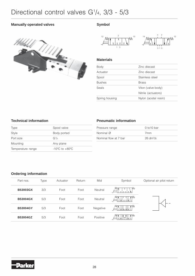
Manually operated valves Symbol
Part nos. Type Actuator Return Mid Symbol Optional air pilot return
B53003GX 3/3 Foot Foot Neutral
B53004GX 5/3 Foot Foot Neutral
B53004GY 5/3 Foot Foot Negative
B53004GZ 5/3 Foot Foot Positive
Ordering information
Pressure range 0 to10 bar
Nominal Ø 7mm
Nominal flow at 7 bar 26 dm3/s
Pneumatic information
Type Spool valve
Style Body ported
Port size G1/4
Mounting Any plane
Temperature range -100C to +800C
Technical information
Body Zinc diecast
Actuator Zinc diecast
Spool Stainless steel
Bushes Brass
Seals Viton (valve body)
Nitrile (actuators)
Spring housing Nylon (acetal resin)
Materials
2 121412 104 2
31 315

Directional control valves G1/4, 3/3 - 5/3
29
3/3 valve dimensions (mm)
Foot pedal operatedspring return
5/3 valve dimensions (mm)
Foot pedal operatedspring return
140
72
10
92
G1/4
27
57
190
9
387689
10,510,5 4,8
4232
140
72
10
G1/4
27
114
212
9 68
387689
21,521,5
4232
4,8
1111

30
Foot guard kit
Directional control valves G1/4
To suit G1/4 foot operated spool valves:B53003FS, B53004FS
The guard completely encloses the valve and is designedto prevent both accidental operation and protect theoperators foot from small metal fragments, dirt and grease.
Manufactured in mild steel, the front edge is protected by arubber strip.
All valve connections are made through the back of theguard, producing a clean design of modern appearance.
The guard kit is supplied complete with valve mountingbolts, nuts and washers.
Part no. 3117
156
162206

31
Directional control valves G1/4
External air supplies
All solenoid-pilot operated valves have internal pilot airsupply from a drilling within the valve, but are providedwith an external port normally sealed by a blanking plug.
Internal pilot supply provides the same pressure for bothmain valve and pilot supply - with the use of external pilotsupply variation of pressure on the solenoid operator ispossible. When using solenoid valves with any mediumother than air, then an external air supply must be made tothe pilot to facilitate valve changeover.
If it is required to use external pilot supply, then theblanking plug should be removed from the port and thesmaller plug contained underneath inserted into theinternal counter bore drilling to seal off the internal airsupply.
For applications using any medium other than air (i.e.vacuum or low pressure oil) we recommend you consultTechnical Sales prior to operation.
Repair kits
Part no. 53007
Part no. 53007
Part no. 53007JR
Part no. 53007SSolenoid pilot operated valves
Air pilot operated valvesDifferential pilot operated valves
Mechanically operated valvesManually operated valves
Lubricating oils
To ensure long life and trouble free service from valves,it is recommended the equipment should be adequatelylubricated by means of lubricators which disperse oil intothe system. Only paraffinic based oils can be used, and thefollowing recommendations are given as a general guideto types of oil that are suitable for use with Parker SchraderBellows airline equipment.
Oil company Grade Viscosity
Century oils P.W.L.A. 32
Alexander Duckham Zircon 4 32
Gulf oil (GB) Limited Harmony 43 AW 32
Shell (UK) oil Tellus 37 37
Burmah Castrol Hyspin AWS 32 32
Edgar Vaughan Y Hydrodrive HP 100 32
Esso Petroleum Nuto H32 32
B.P. HLP 32 32
Mobile Oil Company DTE Oil - Light 32
Motul VPI-A 32
Silkolene Derwent 32 32
The list opposite does not preclude the use of oilsmanufactured by other companies but oils must beparaffinic based.
As a general guide, lubricator drip rates should be 1 drip/minute for every 5 litre/second (10 cubic feet per minute)passed through the equipment.

Parker Hannifin Ltd.Pneumatic Division,Walkmill Lane, Bridgtown,Cannock, Staffs. WS11 0LRUnited Kingdom
We reserve the right to makealterations without prior notification.Edition 09.07
Austria - Wr.NeustadtTel: +43 2622 23501Fax: +43 2622 66212
Belgium - NivellesTel: +32 67 280 900Fax: +32 67 280 999
Czech & SlovakRepublics - KlecanyTel: +420 284 083 111Fax: +420 2 4 083 112
Denmark - BallerupTel: +45 43 560400Fax: +45 43 733107
Finland - VantaaTel: +358 9 4767 31Fax: +358 9 4767 3200
France - ContamineTel : +33 4 50 25 80 25Fax : +33 4 50 25 24 25
Germany - KaarstTel: +49 2131 4016-0Fax: +49 2131 4016-9199
Greece - AthensTel: +30 210 933 6450Fax: +30 210 933 6451
Hungary - BudapestTel: +36 1 220 4155Fax: +36 1 422 1525
Ireland - DublinTel: +353 1 4666370Fax: +353 1 4666376
Italy - Corsico, MilanTel: +39 02 4519 21Fax: +39 02 4479 340
Netherlands - OldenzaalTel: +31 541 585000Fax: +31 541 585459
Pneumatic DivisionSales Offices
Norway - LanghusTel: +47 6491 1000Fax: +47 6491 1090
Poland - WarsawTel: +48 22 573 24 00Fax: +48 22 573 24 03
Portugal - Leça daPalmeiraTel: +351 22 999 7360Fax: +351 22 996 1527
Romania - BucharestTel: +40 21 252 1382Fax: +40 21 252 3381
Russia - MoscowTel: +7 095 580 91 45Fax: +7 095 580 91 46
Slovenia - Novo mestoTel: +386 7337 6650Fax: +386 7337 6651
Spain - MadridTel: +34 91 675 7300Fax: +34 91 675 7711
Sweden - SpångaTel: +46 8 5979 50 00Fax: +46 8 5979 51 20
Switzerland - BolligenTel.: +41 31 917 18 50Fax: +41 31 917 18 59
Turkey - IstanbulTel: +90 212 482 91 06Fax: +90 212 482 91 10
UK - Cannock
Tel: +44 1543 456000Fax: +44 1543 456001
Ukraine - KievTel: + 380 44 494 2731Fax: + 380 44 494 2730
www.parker.com