directive 1a-5 design manual phase - state university ... · web viewdirective 1a-5 directive...
TRANSCRIPT

STATE UNIVERSITY CONSTRUCTION FUND
P R O G R A M D I R E C T I V E SDIRECTIVE 1A-5 Issue date: August 2012
DESIGN MANUAL PHASE
1. General Instructions
a. Provide options for significant decisions required by the client during the Design Manual Phase. Present drafts of options and revise each to reflect comments made by the Fund and the campus. Present revised drafts of options and revise the selected option to reflect comments made. Present the revised, selected option to the Fund and the campus for approval.
1) To assist the campus in reaching a consensus on decisions required to complete the Design Manual Phase, develop a summary of each issue using an iterative process to incorporate campus and Fund input. Use the format preferred by the campus and list factors, benefits, detriments and impacts applicable to the issue.
2) Provide analyses of the options to determine whether the possible options fit the funds available for the project.
3) Consider constructability issues continuously throughout the design effort and make recommendations concerning the impact of the contractor's work on Campus operations.
4) Provide analyses of project execution and the potential construction contract options to determine the desirable option(s) for sequencing the work in phases that fit the capabilities of the available bidders, the potential need to defer construction of portions of the project due to funding restrictions, the availability of work areas and other factors requested by the Fund and campus.
b. The phase submission must satisfy all comments made on last phase report. Response to previous review comments is required. The response must clearly describe the action taken and fully address all questions raised; Reference the drawing number or specification section where appropriate.
c. SUCF shall review a draft of the report before the formal submission. The Design Manual Phase checklist is to be completed and submitted with the draft report.
Office of Pre-Construction Services - Design August 2012 Page 1Design Manual Phase Directive 1A-5

STATE UNIVERSITY CONSTRUCTION FUND
P R O G R A M D I R E C T I V E S
d. The formal submission shall include the cost estimate in CSI format identifying the quantities and unit prices for each system in the Estimate Summary. Provide a comparison of any changes from the last approved estimate. The Estimate Summary shall follow the formats as shown in SUCF Publication "Project Cost Reporting"; separating site, rehabilitation, and new construction. An editable version shall be submitted electronically to the Design Coordinator.
1) For new buildings, additions and Alteration Level 3 projects, provide a list of viable value management deductions equal to at least 10% of the total construction cost estimate (or other percentage, when approved by the Fund, that is more appropriate to the project size, type, the level of design completion, etc.)
2) The purpose of the value management deductions is to facilitate timely decisions on scope and cost by providing a viable alternative to adding funds to the budget. Viable value management deductions are ones that can be realistically implemented in terms of the level of design completion, program constraints, operational constraints, schedule constraints, code compliance, constructability and other factors requested by the campus and the Fund.
3) For other projects not covered by 1d(a) above, when requested by the Fund or when the estimate exceeds the budget, provide a list of viable value management deductions, if any, that can be realistically implemented when considering the project scope.
e. The Consultant and each sub-consultant shall provide a letter on company letterhead, signed by a principal member of the firm that certifies that the quality and completeness of the documents has passed their review and the quality of the documents submitted meet the requirements of the Fund.
2. Design Manual Report
a. The following information is to appear on the cover sheet: Project No., Project Name, Name of College, Name of Architect, Consultants, and issue date.
b. Six (6) copies (pages to be numbered); confirm actual number of sets and mailing directive with SUCF coordinator.
Office of Pre-Construction Services - Design August 2012 Page 2Design Manual Phase Directive 1A-5
STATE UNIVERSITY CONSTRUCTION FUND
P R O G R A M D I R E C T I V E S
c. The Report is to expand upon the previous phase report and does not require resubmission of the unchanged reports and appendices.
d. Include copies of all meeting minutes, checklist, Fund and College comments, and the consultant(s) response to those comments in the appendix of the phase report.
e. Area Summary and Program/Design Deviation:
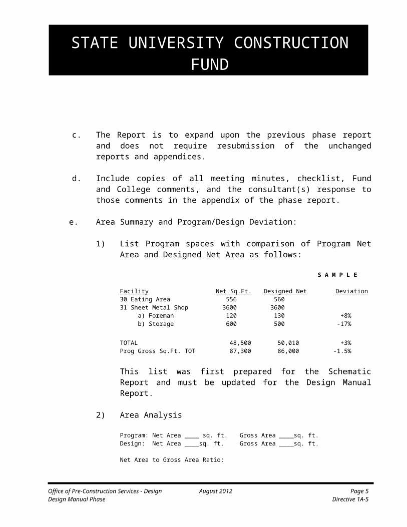
1) List Program spaces with comparison of Program Net Area and Designed Net Area as follows:
S A M P L E
Facility Net Sq.Ft. Designed Net Deviation30 Eating Area 556 56031 Sheet Metal Shop 3600 3600 a) Foreman 120 130 +8% b) Storage 600 500 -17%
TOTAL 48,500 50,010 +3%Prog Gross Sq.Ft. TOT 87,300 86,000 -1.5%
This list was first prepared for the Schematic Report and must be updated for the Design Manual Report.
2) Area Analysis
Program: Net Area ____ sq. ft. Gross Area ____sq. ft.Design: Net Area ____sq. ft. Gross Area ____sq. ft.
Net Area to Gross Area Ratio:
Design Net: Design Gross = 1 : ( )Program Net: Program Optimum Gross = 1: ( )
3) Consultant's verification that his design has included all functional and special requirements of Facilities Program and Site Program, except the following deviations (if none, specify “NONE”):
S A M P L E
Special Program DesignRequirements Solution DeviationNo. 5 Faculty Offices 11 @ 115 + 1 Fac. Office
Office of Pre-Construction Services - Design August 2012 Page 3Design Manual Phase Directive 1A-5
STATE UNIVERSITY CONSTRUCTION FUND
P R O G R A M D I R E C T I V E S(10 @ 120)
No. 29 Lecture Hall 228 seats - 12 seats(240 seats)
Parking (200 cars) 215 cars + 15 cars
Note: Update this list at Design Manual as noted in (a) above.
4) Program Changes made by the campus:List all Program clarifications with reference to letters, minutes or meetings, etc.
f. Site Description includes, as applicable, the following:
1) Brief description of design concept to cover the relationship to campus plan/vocabulary, spatial relationship, contour/ grading, land use, and circulation (vehicle/pedestrian) system. Coordinate design options with Storm Water Pollution Prevention Plan development.
2) Brief description of site improvements, earthwork, site utilities connections and capacities, erosion/sediment controls, and other engineering aspects.
3) Brief description of major landscape features, including planting concept, walls/stairs, site furniture, site lighting and environmental considerations related to air, water and noise pollution.
4) Provide storm drain system calculations, water system required flow and pressure calculations (domestic and fire protection) and sanitary system calculated peak flow. Unless included in the lump sum fee or the Schedule B of the Consultant’s Agreement, the services and fees related to measuring and documenting existing conditions may be provided through extra compensation when approved by the Fund.
5) Identify routes of firefighting equipment, service access, refuse disposal, and snow removal patterns.
6) The recommendations on building foundation, planting, paving, drainage, waterproofing, etc., based on subsurface investigation and/or site utilities reports submitted previously.
Office of Pre-Construction Services - Design August 2012 Page 4Design Manual Phase Directive 1A-5
STATE UNIVERSITY CONSTRUCTION FUND
P R O G R A M D I R E C T I V E S7) Brief description and type of service vehicle or equipment for which
loading facilities, trash removal, window washing or road/walkway systems are to be designed.
Office of Pre-Construction Services - Design August 2012 Page 5Design Manual Phase Directive 1A-5

STATE UNIVERSITY CONSTRUCTION FUND
P R O G R A M D I R E C T I V E Sg. Summarize environmental considerations related to air, storm water, water
and noise pollution.
h. Building Description includes the following, as applicable:
1) Brief description of design concept to cover relationships to campus plan design vocabulary (if appropriate), spatial form and massing.
2) Brief description of architectural elements. List of proposed exterior and interior finishes for major and typical areas or spaces.
3) Brief description of the structural system, including table of design load based on function or space for all areas of the building.
4) Identify the structural system, including materials and system and the table of design loads based on function or space for all areas of building. Confirm that the design complies with the geotechnical recommendations. Include bearing capacity, anticipated settlement and other pertinent design factors.
i. Code Conformance: Summarize status of code requirements. All items required for the Schematic Design submission shall be resubmitted in the Design Manual phase submission, updated as necessary.
1) In addition, articulate requirements and solutions including fire safety items, including access by the fire department and window washing provisions. Supplement with written information, any items that cannot be fully shown on the Code Conformance drawings.
2) Append copies of typical campus hot work permits, other documents that may be developed by the Campus Fire Prevention Program Superintendent and other special conditions.
j. Mechanical system (HVAC, plumbing, electrical and signal) includes the following, as applicable:
1) HVAC: Provide a written description of each system. Describe the system type, system operation, all required utility connections and the equipment location. The system report shall include the following:
i. Provide a description of the proposed Building Management
Office of Pre-Construction Services - Design August 2012 Page 6Design Manual Phase Directive 1A-5

STATE UNIVERSITY CONSTRUCTION FUND
P R O G R A M D I R E C T I V E SSystem. Identify each system by manufacturer and generation. The description shall identify the existing Building Management System, if applicable, and discuss requirements for connecting new equipment to the existing.
ii. The criteria used in sizing and selecting equipment and the origin of this criteria (i.e. ASHRAE or other design manuals, Program Directives, Campus request, code requirement, etc.)
iii. A description of the required space for major elements of the system. This should include mechanical equipment rooms, space above the ceiling and shafts.
iv. A description of building access routes for equipment installation and how this equipment will be removed and new equipment installed at a future date.
v. Describe required maintenance and the space necessary to perform the maintenance (i.e. coil tube pull, filter replacement, etc.).
2) Provide an analysis of mechanical system design on a room basis. Include room occupancy, heating and cooling loads, acoustical requirements, humidity requirements and special conditions requirements.
3) Provide a sequence of operation for each piece of major equipment. This sequence shall describe the intended operation of major equipment, but need not include hardware requirements.
4) Provide detailed heating and cooling loads when requested. Loads are to be prepared using a computer-based program.
5) Plumbing and Fire Safety
i. A detailed description of the proposed plumbing and fire safety systems.
ii. Design demand for completed project for storm/sewer water, gas, chilled water, electricity, etc. and coordinate with site utility improvements.
Office of Pre-Construction Services - Design August 2012 Page 7Design Manual Phase Directive 1A-5

STATE UNIVERSITY CONSTRUCTION FUND
P R O G R A M D I R E C T I V E Siii. Description of code-required plumbing fixtures including the
number of fixtures and identification of which fixtures are to be ADA accessible.
iv. Describe code-required fire protection equipment. Include, where required, the need of a fire pump and emergency generator. Identify the fuel required for the generator operation.
(6) Electrical and Communications
i. Provide a description of peak electrical load and desired lighting level for each space.
ii. Provide detailed electrical load calculations with appropriate demand factors to support the sizing of the service and emergency generators.
iii. Describe the required communication interface. Include the number of inputs and type of wiring required.
iv. For “smart” type classrooms identify the routing of communication wiring within the classroom.
v. Analyze the communication requirements and discuss the practicality of incorporating wireless technology.
vi. Describe the proposed routing of communication wiring from the point of use back to the communications closet. Include the proposed method of routing the wiring through the building (i.e. conduit, cable tray, etc.)
vii. Describe fire alarm system and its integration into the campus system. Where visual notification devices of less than 75 candelas are proposed, provide an explanation of why the Fund should accept this “equivalent facilitation.”
viii. Identify the need and discuss the requirements for a Campus card key system.
3. Specifications:
Office of Pre-Construction Services - Design August 2012 Page 8Design Manual Phase Directive 1A-5

STATE UNIVERSITY CONSTRUCTION FUND
P R O G R A M D I R E C T I V E Sa. Provide brief outline specifications. Special attention is required for roofing
flashings and waterproofing systems, structural systems, exterior and interior materials, controls and any proposed proprietary materials or equipment. The outline specifications shall include the following:
Office of Pre-Construction Services - Design August 2012 Page 9Design Manual Phase Directive 1A-5

STATE UNIVERSITY CONSTRUCTION FUND
P R O G R A M D I R E C T I V E S
1) The table of contents shall be in CSI format.
2) For significant anticipated technical specification sections, provide in brief form, the following:
i. General: Description, quality assurance, submittals.ii. Products: Materials (criteria, manufacturers, properties, etc.).iii. Execution: Installation testing, etc.
b. Provide catalog cuts of all major equipment for architectural, mechanical, electrical, plumbing and fire protection systems.
4. Materials Board: Provide samples of all significant finish materials listed in the finish schedule, as applicable. The sample materials must accurately reflect the color, texture and finish of the proposed materials. The finish samples shall be mounted on presentation boards (two sets are required). The material boards to be presented to the Campus.
5. Project Schedule: Design and Construction schedules based on current projection.
Current / Proposed Schedule
Last Schedule Original Project Schedule
Recovery Schedule
Design Manual Phase Submission60% CDs/Constructability ReviewPre-Bid Report SubmissionAdvertisementBid OpeningConstruction CompletionOccupancy
6. Design Manual Graphic documents
a. Site, Civil and Landscape Plans: Review directives associated with site work, including Directive 2-1, Site work Overview for more detailed requirements for general site development and presentation. Project site plan(s) shall be at a minimum scale of 1” = 50’.
1) In general, the Design Manual Submission should expand upon the schematic design and shall identify all work and construction associated with the project and its
Office of Pre-Construction Services - Design August 2012 Page 10Design Manual Phase Directive 1A-5

STATE UNIVERSITY CONSTRUCTION FUND
P R O G R A M D I R E C T I V E Simpacts of the campus.
2) Provide a Key Plan showing relation of project site to campus plan.
3) Provide an Existing Conditions Plan as developed through completion of a topographic field survey. Include all existing structures within a 200 feet radius of the new building and as impacted by other site/utility improvements. See Division 2 directives.
4) Provide a Site Plan that includes overall dimension of any proposed new building and indicate distance to existing buildings, roads and property lines. Location and extent of roads, service drives parking, walks, terraces, athletic fields, etc. Identify major outdoor spaces, the proposed levels, and levels of grade-entrance to building and service. Address site provisions for physically handicapped.
i. Review fire protection requirements including hydrant locations and fire-fighting routes. Show fire apparatus access roads that extend within 100 feet of the point(s) of firefighter access and to the point(s) required for aerial access shown in the Fire Code of NYS. These points should be determined in consultation with the local fire department.
5) Provide total site square foot area or acres. Include Contract Limit Lines (CCL) and include area(s) for extended or new site utilities and staging/storage areas. Identify adjacent active construction contracts and identify conflicts, if any. Show routes of construction access through campus to project site. Include Contractor's parking, staging and material storage area. Show construction fencing, gates, haul routes, excess material spoil area, and stockpile areas. Show Temporary Traffic Control plans.
6) Through development of a grading plan provide existing and proposed contours (one- or two-foot intervals) and spot shots as required. Consider earthwork impacts including use of on-site material, imported material, rock and cut/fill balance as appropriate. Based on discussion with the campus and the Fund’s Construction unit, use of on-site material for non-structural fill and use of on-site topsoil may be permitted when technically feasible.
7) Review storm water management, run-off reduction and sedimentation and erosion control strategies. Provide the site drainage plan and runoff calculations, including narrative for design criteria, assumptions
Office of Pre-Construction Services - Design August 2012 Page 11Design Manual Phase Directive 1A-5

STATE UNIVERSITY CONSTRUCTION FUND
P R O G R A M D I R E C T I V E Sand impacts associated with construction. Refer to Directive 2-4 for sedimentation and erosion control requirement.
8) Provide a Storm Water Pollution Prevention Plan (SWPPP) for submission by the Fund for a SPDES Permit related to construction activities (required for disturbance to one acre or more). Unless included in the lump sum fee or the Schedule B of the Consultant’s Agreement, the SWPPP may be provided through extra compensation when approved by the Fund.
9) Landscape – show all proposed plantings.
10) Review Directive 2-3 for site utility requirements. Provide a site utility plan that includes existing utilities and proposed building services and relocated utilities located within the site and impacted by design. Provide a schedule and sequence on utility relocations, including impacts to the Campus and how the utility relocation effects construction operations.
11) If demolition significant demolition of buildings, site features and utilities is required, provide a separate site demolition plan.
12) Provide preliminary site details and sections.
b. Building drawings shall be drawn at a working drawing scale of 1/8”= 1’ at minimum.
c. Provide code conformance drawings articulating the requirements stated above in 2.i, and all Code requirements for all building levels. The documents shall be updated drawings that address any comments made based on the Schematic Design review.
d. Provide demolition plans for site and rehabilitation projects. These plans shall differentiate between existing work to remain or be removed. Provide demolition plans for each affected discipline.
1) For existing spaces where components are removed and replaced, such as windows, fan coil units, etc., provide phasing plans.
2) Show typical large scale details, showing removals and protection for typical demolition work.
Office of Pre-Construction Services - Design August 2012 Page 12Design Manual Phase Directive 1A-5

STATE UNIVERSITY CONSTRUCTION FUND
P R O G R A M D I R E C T I V E S
3) Provide schedules, keyed notes, etc. for removals as appropriate to the design.
Office of Pre-Construction Services - Design August 2012 Page 13Design Manual Phase Directive 1A-5

STATE UNIVERSITY CONSTRUCTION FUND
P R O G R A M D I R E C T I V E S4) Show the temporary partitions required by NFPA 241.
5) Show the closed exits, the temporary alternate routes that replace closed exits, or note the reduced occupancy if exits are not temporarily replaced.
6) Show the extent of temporary protection and other temporary work required to permit continued occupancy by the campus. Show egress details that comply with Section 1009 of the Code.
7) Show existing and/or new permanent, combustible construction, if any, on the drawings and note protection of such construction per NFPA 51B.
e. Provide hazardous material drawings for site and rehabilitation projects. Show quantities for all materials.
f. Architectural drawings shall include:
1) Symbol list.
2) Detailed floor plans (all levels): Provide room name and number for all programmed spaces. Coordinate room number with existing room numbering system as appropriate, and approved by the Fund. For rehabilitation projects include the existing floor plan and indicate the existing space usage and the proposed usage. Indicate proposed materials on roof. Plans show all floor drains and direction of slope. Floor plans shall indicate access paths for the installation, removal, or replacement of all major mechanical and electrical components.
3) The floor plans shall include the following:
i. The overall dimensions of major elements.
ii. Indicate location of rated walls, fire separations, fire doors, exit enclosures and similar code required features.
iii. Indicate location of doors (including door swing) and windows.
Office of Pre-Construction Services - Design August 2012 Page 14Design Manual Phase Directive 1A-5

STATE UNIVERSITY CONSTRUCTION FUND
P R O G R A M D I R E C T I V E Siv. Identify the location of all plumbing fixtures including water
coolers, water closets, urinals, lavatories, service sinks, floor drains, etc. Identify the required handicap fixtures.
v. Identify the location of built in features including laboratory equipment, casework, kitchen equipment, counters, lockers, etc.
vi. All “in contract” equipment must be shown. Significant NIC and typical equipment and furniture are to be shown per the SUCF coordinator.
vii. Provide a furniture plan that identifies moveable furnishings, partitions, etc. Identify moveable furnishings that are not in contract as NIC.
viii. Provide a separate demolition plan whenever demolition within an existing building is required. This plan shall differentiate between existing work to remain and existing work to be removed.
ix. Provide a roof plan indicating the location of any roof mounted equipment, roof drains, roof slope, etc.
x. Full building sections - indicate major levels and ceiling heights.
(a) Show at scale that provides the appropriate clarity of detail.
(b) Show parapets, overhangs, soffits, arches and other significant physical characteristics.
(c) Show air barrier and insulation that is consistent with the Energy Model and ECCCNYS
(d) Show effectiveness of shading where sun shading in proposed.
(e) Where applicable, show earth retention, utility tunnels unexcavated areas, etc
xi. Detailed elevations (all faces) – Include all building elements such as penthouses, entrances, stairs, windows, louvers, exhaust stacks, etc. Indicate the proposed finished grades. Also, indicate exterior color and materials.
Office of Pre-Construction Services - Design August 2012 Page 15Design Manual Phase Directive 1A-5

STATE UNIVERSITY CONSTRUCTION FUND
P R O G R A M D I R E C T I V E Sxii. Indicate overall building and floor heights.
xiii. Include longitudinal and transverse sections for all major areas. Identify floor to floor height, ceiling height, basement areas, roof height, parapet and proposed finished grades. Where applicable, identify utility tunnels unexcavated areas, etc.
xiv. Sections shall identify the space required for routing the mechanical systems. Provide ¼” sections through corridor showing lighting, cable tray, ductwork, and structural steel.
xv. All sections and elevations shall be referenced on the floor plan.
xvi. Interior Details (scale as appropriate)
xvii. Provide detailed plans, sections and elevations (1/4” scale) of all major spaces:
xviii. Typical wall sections.
xix. Critical building details:
(a) Parapet wall and roof(b) Roof deck section(c) Expansion joints(d) Waterproofing(e) Window and Exterior(f) Doors(g) Others as necessary
xx. Reflected ceiling plans.
xxi. Room layouts based on final equipment program including both In-Contract and Not-In-Contract equipment.
4) Schedules
i. Provide a preliminary interior finish schedule. The schedule shall identify materials, texture and color for each proposed finished material.
Office of Pre-Construction Services - Design August 2012 Page 16Design Manual Phase Directive 1A-5

STATE UNIVERSITY CONSTRUCTION FUND
P R O G R A M D I R E C T I V E Sii. Provide a preliminary door schedule identifying door type, door
label, material, frame and hardware.
iii. Provide preliminary schedules for window, in-contract equipment, etc., as appropriate to the design.
Office of Pre-Construction Services - Design August 2012 Page 17Design Manual Phase Directive 1A-5

STATE UNIVERSITY CONSTRUCTION FUND
P R O G R A M D I R E C T I V E S
g. Structural
1) Single-line floor and roof framing system; also, identify materials. Indicate grid system (dimensioned), columns, load bearing walls, footings, etc.
2) Basement and foundation plans.
3) Floor and roof framing plans (show direction of roof slope).
4) Typical sections, details, schedules as necessary to convey design progress.
5) Where existing systems are modified or demolished, provide demolition plans, sections and detail as appropriate.
h. HVAC, Plumbing and Electrical
1) HVAC
i. Schematic diagrams for all air and water systems including sizing of piping and ductwork.
(a) Provide air riser diagrams for supply, return and exhaust systems. Ductwork mains are to be sized.
(b) Provide hydronic riser diagrams for heating and cooling systems. Pipe mains are to be sized.
ii. Provide riser diagrams for steam and condensate systems including sizing of pipe mains.
iii. All equipment (boilers, heat exchangers, chillers, pumps, air handling units, fans, etc.) shall be located in the mechanical equipment rooms. Access for maintenance and future removal is to be identified.
iv. Layout and sizing of the main ductwork and piping runs serving the major equipment. Include the airflow and water flow rates.
Office of Pre-Construction Services - Design August 2012 Page 18Design Manual Phase Directive 1A-5

STATE UNIVERSITY CONSTRUCTION FUND
P R O G R A M D I R E C T I V E S
v. Floor plans are to indicate the general piping and ductwork layout. VAV Terminal units, reheat coils, fin tube radiation, etc. are to be included. The design shall clearly illustrate the zoning approach.
vi. Indicate the locations of pipe chases and duct shafts.
vii. Fully developed typical areas shall be provided. The design shall include ductwork and pipe sizes, airflow rates, water flow rates etc. Typical areas include classrooms, lecture halls, laboratories, offices, computer rooms, atriums, conference rooms, etc.
viii. Location of all required fire and smoke dampers. Location is to be coordinated with the architectural plans.
ix. Mechanical room floor plans shall be drawn at 1/4” scale. A minimum of two sections through each room will be provided one of each view. All equipment visible from a view is to be shown. Sections at 1/4” scale are also required for congested areas. Examples of congested area would be the space above the corridor ceiling, space above a laboratory ceiling, etc. Ductwork with a dimension 6” or larger and piping 4” or larger in diameter shall be shown double line to scale.
x. All ductwork and piping is to be shown on the floor it is installed. Ductwork with a dimension 6” or larger and piping 4” or larger in diameter shall be shown double line to scale.
xi. In rehabilitation projects the point of connection to existing utilities is to be shown. The capacity of the existing system is to be noted.
xii. Preliminary single line diagram of the building temperature control system architecture is required.
xiii. Provide a preliminary DDC point schedule.
Office of Pre-Construction Services - Design August 2012 Page 19Design Manual Phase Directive 1A-5
STATE UNIVERSITY CONSTRUCTION FUND
P R O G R A M D I R E C T I V E Sxiv. Provide a preliminary equipment schedule for all equipment.
Provide sufficient data to verify the capacity of major equipment (major equipment as defined above).
xv. Provide mechanical equipment or system details.
xvi. This work shall be properly coordinated with site utilities drawings. Refer to Directive 2-3.
xvii. Where existing systems are modified or demolished, provide demolition plans.
2) Plumbing and Fire Protection
i. Floor plans are to indicate the general piping layout and sizes. Indicate locations of main waste lines, stacks, vents, water, gas, vacuum, air, etc.
ii. All major equipment is to be located in the mechanical room and is to be shown. Equipment includes tanks, pumps, chemical treatment system, emergency generator, backflow prevention devices, pressure reducing valves, fire pumps and special equipment.
iii. Indicate the locations of pipe chases.
iv. Fully developed typical areas shall be provided. The design shall include all piping and fixtures, sprinklers, etc. Typical areas include classrooms, lecture halls, laboratories, offices, computer rooms, atriums, conference rooms, toilet areas, etc.
v. All piping is to be shown on the floor it is installed. Piping 4” or larger in diameter shall be shown double line to scale.
vi. A roof plan is to be provided which locates all roof drains and identifies the direction of slope for all surfaces.
vii. This work shall be properly coordinated with site utility drawings. Refer to Directive 2-3.
Office of Pre-Construction Services - Design August 2012 Page 20Design Manual Phase Directive 1A-5

STATE UNIVERSITY CONSTRUCTION FUND
P R O G R A M D I R E C T I V E Sviii. Indicate the location of plumbing work required for the fire
protection system. This includes standpipes, mains, building service, flow switches, floor control valve assemblies, etc.
ix. Plumbing mechanical room floor plans shall be drawn at 1/4” scale. A minimum of two sections will be provided one of each view. All equipment visible from a view is to be shown. Sections at 1/4” scale are also required for congested areas. Examples of congested area would be the space above the corridor ceiling, space above a laboratory ceiling, etc.
x. Provide a preliminary equipment schedule for all equipment. Provide sufficient data to verify the capacity of major equipment (major equipment as defined above).
xi. Provide plumbing equipment details and system schematics.
xii. Riser Diagrams (Sanitary [waste], Storm [roof drains] and Sprinkler/Standpipe Systems, etc.)
xiii. Standpipe layout.
xiv. Sprinkler layout. Where existing systems are modified or demolished, provide demolition plans.
3) Electrical
i. Finalized primary service connections.
ii. Fully developed typical areas shall be provided. The design shall include location and type of lighting fixture, electrical, data requirements. Typical areas include classrooms, lecture halls, laboratories, offices, computer rooms, atriums, conference rooms, toilet areas, etc.
iii. Power, signal and communications layout shall be shown on one set of drawings. The lighting layout shall be shown on a separate set of plans.
Office of Pre-Construction Services - Design August 2012 Page 21Design Manual Phase Directive 1A-5

STATE UNIVERSITY CONSTRUCTION FUND
P R O G R A M D I R E C T I V E Siv. Provide a single-line diagram indicating the primary service
configuration, the secondary distribution to switchboards, motor control centers and panels.
v. Provide the size of all transformers, fused switches, circuit breakers, automatic transfer switches, etc.
vi. Provide the conductor size for all major feeders.
vii. Provide preliminary schedule for panel board, motor control center and automatic transfer switch.
viii. Provide a light fixture schedule.
ix. Indicate the location of all exit signs.
x. All major equipment is to be located in the electrical room and is to be shown. This plan shall be drawn at 1/4” scale and must indicate access for maintenance and future removal.
xi. This work shall be properly coordinated with site utility plans, including transformers, connection to existing systems and site lighting.
xii. Equipment identification and layout for both primary and secondary systems.
xiii. Floor lighting layout.
xiv. Lighting fixture schedule (include fixtures for major space and other typical fixtures).
xv. Where existing systems are modified or demolished, provide demolition plans.
4) Communication and Emergency Systems:
i. Riser diagrams for telephone, data, fire alarm, emergency lighting and exit signs.
Office of Pre-Construction Services - Design August 2012 Page 22Design Manual Phase Directive 1A-5

STATE UNIVERSITY CONSTRUCTION FUND
P R O G R A M D I R E C T I V E Sii. For smoke detection, provide plans showing ceiling vaults, beams,
coffers, etc. that impact device location.
iii. Where existing systems are modified or demolished, provide demolition plans.
7. Massing Study – Model, perspectives, or computer-generated walk-through updated to reflect the Design Manual design.
* * * * * *
Office of Pre-Construction Services - Design August 2012 Page 23Design Manual Phase Directive 1A-5