directselective lasersintering andcontainerless ... · post-processedto full density by...
TRANSCRIPT

Direct Selective Laser Sintering and Containerless Hot Isostatic Pressingfor High Performance Metal Components
Suman Das, Martin Wohlert, Joseph J. Beaman, David L. BourellLaboratory for Freeform Fabrication
University of Texas at Austin
AbstractA novel net shape manufacturing method known as SLSIHIP that
combines the strengths of selective laser sintering (SLS) and hot isostatic pressing(HIP) is presented. Direct selective laser sintering is a rapid manufacturingtechnique that can produce high density metal components of complex geometrywith an integral, gas impermeable skin. These components can then be directlypost-processed to full density by containerless HIP. The advantages of in-situHIP encapsulation include elimination of a secondary container material andassociated container-powder interaction, reduced pre-processing time, a short HIPcycle and reduction in post-processing steps compared to HIP of canned parts.Results of research conducted on Inconel 625 superalloy, Ti-6AI-4V and Monelare presented. This research is funded by DARPAlONR contract N00014-95-C0139 titled "Low Cost Metal Processing Using SLSIHIP".
INTRODUCTION
Selective laser sintering (SLS) is a layered manufacturing technique that can producefreeform three-dimensional objects directly from their CAD models without part specific toolingor human intervention. Parts are built by selectively fusing layers of apowder material using ascanning laser beam. Details on this process are described elsewhere1
, • Selective laser sinteringtechnology for prototyping parts in a variety of polymeric materials and for creating investmentcasting patterns has been commercially developed by DTM Corporation. More recently,RapidTool™ technology for creating prototype injection molding tooling has been introduced3
•
This process is an indirect SLS technique that involves the use of polymer coated metal powdersto produce a produce a green shape that is sUbse~uently post-processed by binder burnout andinfiltration to produce a fully dense object4
,5,6,7,8, • Demand for low volume functional metalprototypes at reduced cost and short lead time has spurred the development of so-called directfabrication processes. A number of such next-generation direct fabrication processes are underdevelopment. These processes typically use a concentrated energy source to consolidate andproduce a fully dense or nearly fully dense shape directly from constituent materials. The nextgeneration of selective laser sintering, Le. direct fabrication of functional metal and cermetcomponents and tooling is under development at the University of Texas10,11,12. To produce fulldensity metal parts having complex geometry, a novel net shape manufacturing technique calledSLSIHIP is under development at the University of Texas. The idea is to consolidate the interiorof a component to 80% or higher density and to fabricate an integral gas impermeable skin or"can" at the part boundary in-situ. The SLS processed part can then be directly post-processedby containerless HIP to full density. A final machining step will result in a part having thedesired geometry and mechanical properties.
81

BACKGROUND
The Department of Defense has a number of high value, high performance metalcomponents in service that are produced by hot isostatic pressing. These parts are typicallyproduced by conventional HIP of canned metal powders. Shaped metal cans are commonly usedto encapsulate metal powders for HIP. The sheet metal container material is chosen so as tominimize interaction with the powder at processing temperatures. The container material mustbe removed by machining or by chemical methods after HIP post-processing. Properties of thecan material including its melting temperature impose processing limits on the shaped metalencapsulation method.
Complex shapes are typically produced using the ceramic mold process13 developed byCrucible Materials. This process is similar to investment casting in that dry powder instead ofmolten metal is poured into a ceramic mold. The production of a near net shape is advantageousbecause it minimizes scrap losses and machining steps. However, outgassing and heating cyclesare long during this process because the ceramic mold is surrounded by a large volume ofpressure transmitting medium14
• The long cycle time and pre-processing steps necessary in theceramic mold method make it a time consuming and expensive process. In addition, nonmetallic contamination is also possible.
In the SLSIHIP process (Figure 1), the component is produced by selectivelyconsolidating a metal powder with a laser beam layer by layer. While producing each layer, agas impermeable high density skin (> 98% density) is formed at the boundaries of the part. Theinterior of the part is laser processed to a high density typically exceeding 80%. Thus, the part isshaped and canned in-situ. The encapsulated part is evacuated, sealed and post-processed bycontainerless HIP to full density. A final machining step may be applied if necessary.
SLSIHIP has several advantages over conventional HIP methods. Since an integral skinor "can" is formed of the same material as the part, a secondary canning step is not necessary.The part is directly post-processed by containerless HIP. Adverse container-powder interactionsare eliminated and post-HIP container removal is not required. SLSIHIP allows production ofcomplex shapes at reduced cost and shorter lead-times.
Based upon on a survey of several naval installations15, four candidate materials havebeen selected for SLSIHIP process development. These are Inconel® 625, Ti-6AI-4V, 17-4PHstainless steel and Molybdenum. Table 1 below summarizes demonstration components andtheir applications.
Material Component ApplicationInconel625 (Engine Vane lAircraft turbine engine componentTi-6Al-4V lHousing base Tactical missile body component17-4PH SS tink assembly Tactical missile launcher componentMolybdenum Rotary valve Torpedo component
Table 1 SLSIHIP demonstration components
82
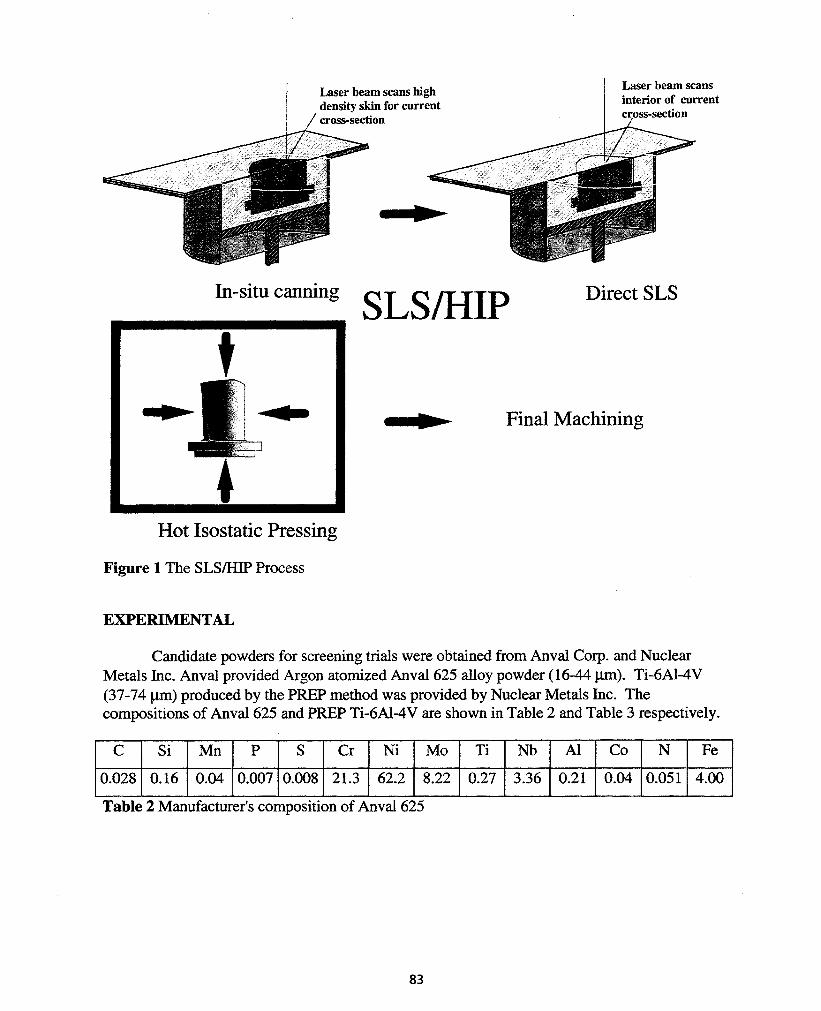
Laser beam scans highdensity skin for currentcross-section
Laser beam scansinterior of currentcross-section
In-situ canning SLSIHIP Direct SLS
Final Machining
Hot Isostatic Pressing
Figure 1 The SLSIHIP Process
EXPERIMENTAL
Candidate powders for screening trials were obtained from Anval Corp. and NuclearMetals Inc. Anval provided Argon atomized Anval625 alloy powder (16-44 J.lIIl). Ti-6Al-4V(37-74 J.lIIl) produced by the PREP method was provided by Nuclear Metals Inc. Thecompositions of Anval 625 and PREP Ti-6Al-4V are shown in Table 2 and Table 3 respectively.
C Si Mn P S Cr Ni Mo Ti Nb Al Co N Fe
0.028 0.16 0.04 0.007 0.008 21.3 62.2 8.22 0.27 3.36 0.21 0.04 0.051 4.00
Table 2 Manufacturer's composition of Anval 625
83

Al V Fe 0 C N H Y Ti
6.35 4.19 0.19 0.19 0.02 0.01 <0.01 < 0.001 Bal
Table 3 Manufacturer's composition of PREP Ti-6AI-4V
Characterization of the powders used in the SLSIHIP experiments included observationof the powder morphology by SEM and measurement of the powder surface area by gasadsorption surface area analysis (BET method).
Morphology
Both the Inconel625 and Ti-6Al-4V powders were quite spherical, as would be expectedfor gas atomized and PREP powders. The high degree of sphericity provided excellent flowcharacteristics. A free flowing powder is important for SLS since the powder layers must besmooth and uniform. The presence of some particle rearrangement as material is drawn into themelt pool beneath the laser beam has also proven beneficial. The micrographs indicate adendritic surface structure for both powders, but the presence of some segregation is notproblematic since the material is melted and resolidified during the SLS process.
Figure 2 SEM micrographs of -325 mesh Anval625 (left) and -200 mesh PREP Ti-6AI-4V (right)
Surface Area Analysis
The surface area of the powder is of greater concern, since the material must bethoroughly degassed prior to SLS processing. There are indications that the presence of oxideformation during SLS processing is a significant factor in influencing both the mechanicalproperties and the part density following the SLS stage. A 5-point BET surface area analysis(Table 4) was performed on the powder using a Micromeritics ASAP 2010 Surface areaAnalyzer. Samples of Inconel 625 and Ti-6Al-4V weighing 26 gm and 18 gm respectively weredegassed at 3500 C for 24 hours.
84

lMaterial Predicted Area (m2/f!.) Measured Area (m2/f!.)IInconel 625 0.035 0.052IPREP Ti-6AI-4V 0.034 0.0686Table 4 BET Surface area analysis
Leak testing
To screen specimens produced by SLS for impermeability, a leak testing apparatus andprocedure was adapted from the Metals handbook article on containerless HIP I6
• For a specimento be acceptable for HIP, a gas impermeable barrier must be provided. A helium leak rate lessthan 1 X 10⁻⁹ standard cm3/s is considered acceptable. Such low leak rates are required becausethe leak rate at typical a HIP pressure of 1000 atm (100 MPa) will be five orders of magnitudegreater than that during leak testing at 1 atmosphere.
Feasibility demonstration
To demonstrate feasibility of constructing a thin walled can acceptable for HIP, arectangular geometry was chosen. The procedure established to qualify specimens and to refineSLS processing parameters is shown in the flowchart of Figure 3. A schematic of the testgeometry is shown in Figure 4.
SLS
Refine
Microstructure Evaluation
Leak test
Microstructure Evaluation
Pass
HlP
Fail
Build 1direction
Laser scan pattern
_-.~. 1°4'
10.125"4 •
1.2"
Figure 3 Specimen qualification procedure Figure 4 Thin wall specimen schematic
SLS apparatus
SLS trials were conducted on a high temperature selective laser sintering machinedesigned and built at the University of Texas. This machine is equipped with a 250 WattNd:YAG laser, powder preheating capability up to 600° C and controlled atmosphere.
85

HIP apparatus
HIP trials were conducted on a ABB model QIH-3 equipped with a graphite heatingelement. Temperatures up to 2000° C and pressures up to 200 MPa are attainable with thegraphite element in inert atmosphere. Argon gas was used as the pressure transmitting medium.
RESULTS AND DISCUSSION
To demonstrate feasibility of constructing gas impermeable thin walls by SLS, specimensconforming to the geometry of Figure 4 were produced. These were then leak tested andscreened according the procedure in Figure 3. Shown on the left in Figure 5 is the cross-sectionof a thin wall specimen produced by SLS. This specimen passed the leak test with a helium leakrate of less than 1 X 10 -10 standard cm3/s. This specimen was post-processed by a HIP cycleconsisting of 1 hour at 1100 °C and 30 mTorr pressure followed by 45 minutes at 1100° C at 66MPa. A cross-section of the HIPed specimen is shown on the right. Average porosity wasmeasured over a metallographic montage in as SLS processed and HIPed specimens revealing adecrease in average porosity from 4.5% to 3.7%.
':.,. ..,', ~ ,, ;, ." .
, ...- .r-.. t ~ •
' .
.j.. ... ,""" .1-~
Figure 5 InconeI 625 Specimen 121496, as SLS processed (left) and HIP post-processed (right)
The next step in SLSIHIP process development was to demonstrate capability ofconstructing a simple shape. A 0.5 inch diameter, 0.5 inch long cylinder was chosen for thispurpose. Shown in Figure 6 is an axial cross-section of an Inconel 625 cylinder processed bySLS to 98.5% density. This specimen was post-processed by a HIP cycle consisting of 3 hoursat 1240 ° C and 25000 psi. This cycle resulted in nearly full densification to 99.5%. A crosssection of the HIPed specimen is shown in Figure 6 Specimen 051797, as SLS processed, 1.5%porosity. Temperature and pressure HIP maps (Ashby) were generated using softwaredeveloped by one of the authors (Bourell). The objective was to correlate experimentallyobserved density with predicted density. These maps show that for Inconel 625 parts with initialdensity in excess of 98%, the dominant mechanism of densification at temperatures higher than1100° C and pressures in excess of 100 MPa (15 ksi) is power law creep. The maps predict thatHIPing conditions of 1100° C and 100 MPa should be sufficient to densify Inconel 625 in excess
86

of 98% density in 1 hour. To ensure full density, a more aggressive HIP cycle consisting of 3hours at 12400 C and 165Mpa (25ksi) was employed.
Figure 6 Specimen 051797, as SLS processed, 1.5% porosity (left) and HIPed, 0.5% porosity(right)
Power Law Creep(II) Stress
1100 1300
Yielding
900
Power Law Creep(I) Stress
l~-----::;;;;=o:::::::==,-:::::==-----~
0.98
0.96.~ 0.94 ~~-?-"" I~ 0.92 1-1'~:;"""'::;"'-------QII) 0.9>.~ 0.88
~ 0.860.84 ~ I
0.820.8 +----+----+-------1
700100010010
1,--------r-....---,.,,_-----,
0.98
0.96
l;> 0.94.;]
~ 0.92 +----_+-...,~'-----..,Q0) 0.9>.~ 0.88
~ 0.86
0.84
0.820.8 _!!!!!!i!~;""'~~~~+--_~
0.1
Pressure, MPa Temperature, °C
Figure 7 Pressure HIP map (at 1240° C) for Inconel625 (left) and temperature HIP map (at 165MPa) for Inconel625 (right)
Single layer screening trials were conducted on candidate materials Ti-6AI-4V, Monel(65%Cu-35%Ni) and Ti-14Al-21Nb, a Titanium Aliminide. Shown in Figure 8 is a cross-sectionof a PREP Ti-6Al-4V single layer (0.15 cm thickness) produced by SLS. This specimensuccessfully passed the leak test with a helium leak rate less than 1 X 10⁻¹⁰ standard cm3ts.Shown in Figure 9 are cross-sections of Ti-14AI-21Nb and Monel single layer specimensdemonstrating full density capability.
87

Figure 8 PREP Ti-6AI-4V, single layer, as SLS processed
Figure 9 Single layer specimens of PREP Ti-14AI-21Nb (left) and Monel (right)
CONCLUSIONS
The feasibility of SLSIHIP has been successfully demonstrated for a simple cylindricalshape made of Inconel 625 superalloy. Preliminary screening trials on PREP Ti-6Al-4V indicatethat a gas impermeable skin can be produced by SLS. Research is ongoing to qualify additionalmaterials including Monel, Ti-14Al-21Nb, Molybdenum and 17-4PH stainless steel. The nextstep in SLSIHIP process development will be to demonstrate a complex geometry part. SLSIHIPhas tremendous potential for rapid, net shape manufacture of high performance metalcomponents at reduced cost and shorter lead times.
88

ACKNOWLEDGEMENTS
The Laboratory for Freeform Fabrication at the University of Texas gratefullyacknowledges funding support provided by the Defense Advanced Research Projects Agencyand The Office of Naval Research and under DARPA/ONR contract NOOOI4-95-C-OI39 titled"Low Cost Metal Processing Using SLSIHIP". Lockheed Martin Vought Systems is the contractprogram manager.
REFERENCES
i Beaman, Joseph J. and Deckard, Carl R., Solid Freeform Fabrication and Selective PowderSintering, 15th NAMRC, North American Manufacturing Research Conference Proceedings,1987, pp. 636-640.2 Deckard, C.R., Ph.D. Dissertation, Department of Mechanical Engineering, The University ofTexas at Austin, 1988.3 Rapid Prototyping and the Selective Laser Sintering Process: Tooling, product literature, DTMCorporation, Austin, Texas.4 Vail, N.K., Preparation and Characterization ofMicroencapsulated, Finely Divided CeramicMaterials for Selective Laser Sintering, Ph.D. dissertation, Department of Chemical Engineering,The University of Texas at Austin, 1994.5 Vail, N. K., Barlow, J.W. and Marcus H.L., Silicon Carbide Preformsfor Metal Infiltration bySelective Laser Sintering ofPolymer Encapsulated Powders, Solid Freeform FabricationSYmposium Proceedings 1993, The University of Texas at Austin, pp. 204-214.6 Deckard, Lucy and Claar, Dennis T., Fabrication ofCeramic and Metal Matrix Compositesfrom Selective Laser Sintered Preforms, Solid Freeform SYmposium Proceedings 1993, TheUniversity of Texas at Austin, pp. 215-222.7 Stucker, Brent E., Bradley, Walter L., Norasetthekul, Somchin (Jiab) and Eubank, Phillip T.,The Production ofElectrical Discharge Machining Electrodes Using SLS: Preliminary Results,Solid Freeform Fabrication Symposium Proceedings 1995, The University of Texas at Austin,fP.278-286.
Bampton, C.C. and Burkett, R., Free Form Fabrication ofMetal Components and Dies, SolidFreeform Fabrication Symposium Proceedings 1995, The University of Texas at Austin, pp. 342345.9 Wohlert, M. and Bourell, D., Rapid Prototyping ofMg/SiC Composites by a Combined SLSand Pressureless Infiltration Process, Solid Freeform Fabrication Symposium Proceedings 1996,The University of Texas at Austin.10 Fuesting, T., L. Brown, S. Das, N. Harlan, G. Lee, J. J. Beaman, D. L. Bourell, J. W. Barlowand K. Sargent, Development ofDirect SLS Processing for Production ofCermet CompositeTurbine Sealing Components-Part I, Solid Freeform Fabriaction SYmposium 1996 Proceedings,pp.39-46.
Fuesting, T., L. Brown, S. Das, N. Harlan, G. Lee, J. J. Beaman, D. L. Bourell, J. W. Barlowand K. Sargent, Development ofDirect SLS Processing for Production of Cermet CompositeTurbine Sealing Components-Part I, Solid Freeform Fabriaction SYmposium 1996 Proceedings,pp.47-55.
89

12 Das, S., N. Harlan, J. J. Beaman and D. L. Bourell, Selective Laser Sintering ofHighPerformance High Temperature Metals, Solid Freeform Fabrication Symposium 1996Proceedings, pp. 89-95.13 Hot Isostatic Pressing ofMetal Powders, Metals Handbook, Vol. 7, 9 th Edition, pp. 425-426.14 Atkinson, H. V., and B. A. Rickinson, Hot Isostatic Pressing, Adam Hilger: Bristol, England,1991, pp. 64-65.15 Knight, Ronald, Joe Wright, Joseph Beaman, and Douglas Freitag, Metal Processing UsingSelective Laser Sintering and Hot Isostatic Pressing (SLSIHIP), Solid Freeform FabricationSymposium 1996 Proceedings, pp. 349-353.]6 Hot Isostatic Pressing ofMetal Powders, Metals Handbook, Vol. 7, 9th Edition, pp. 436.
90