disassemble n71vn series chapter 02-v1 0
TRANSCRIPT
Disassembly Procedure
V1.0 2 - 1
Disassembly Procedure
Please follow the information provided in this section to perform the complete
disassembly procedure of the notebook. Be sure to use proper tools described
before.
SUS N71VN Series Notebook consists of various modules. This chapter describes the procedure for the complete notebook disassembly. In addition, in between procedures, the detailed disassembly procedure of individual modules will be provided for your service needs.
The disassembly procedure consists of the following steps:
Battery Module
Memory Module
Wireless LAN Module
TV-Tuner Module
HDD Module
ODD Module
Keyboard Module
Top Case Module
LCD Module
Motherboard Module
CPU Module
Bottom Case Module
Chapter
2
A

Disassembly Procedure
V1.0 2 - 2
Battery Module
The illustration below shows how to remove the battery module.
Remove Battery Module
Hold the battery latch and take the battery away.
BACK
Memory Module
The illustration shows how to remove the Memory Module.
Remove Memory Module 1. Remove 3 screws here and take the CPU door away.
B A T T E R Y
M E M O R Y

Disassembly Procedure
V1.0 2 - 3
2. Pull two latches here to pop the Memory module up at 45 angles, and then pull out the module at that angle.
BACK

Disassembly Procedure
V1.0 2 - 4
Wireless LAN Module
The illustration below shows how to remove the Wireless LAN Module from the notebook.
Remove Wireless LAN Module
1. Disconnect the Wireless Land antennas and remove 2 screws here.
2. Pull out the WLAN card from its slot.
BACK
W L A N

Disassembly Procedure
V1.0 2 - 5
TV-Tuner Module
The illustration below shows how to remove the TV-Tuner Module from the notebook.
Remove Wireless LAN Module
1. Disconnect the TV-Tuner antenna.
2. Remove 2 screws here and pull out the TV-Tuner card from its slot.
BACK
T V - T U N E R

Disassembly Procedure
V1.0 2 - 6
HDD Module
The illustrations below show how to remove the HDD Module from the notebook.
Remove HDD Module
1. Remove 2 screws here and take the HDD door away.
2. Remove 2screws on each HDD bracket. Lift up the two HDD modules and take it away.
H D D
Disassembly Procedure
V1.0 2 - 7
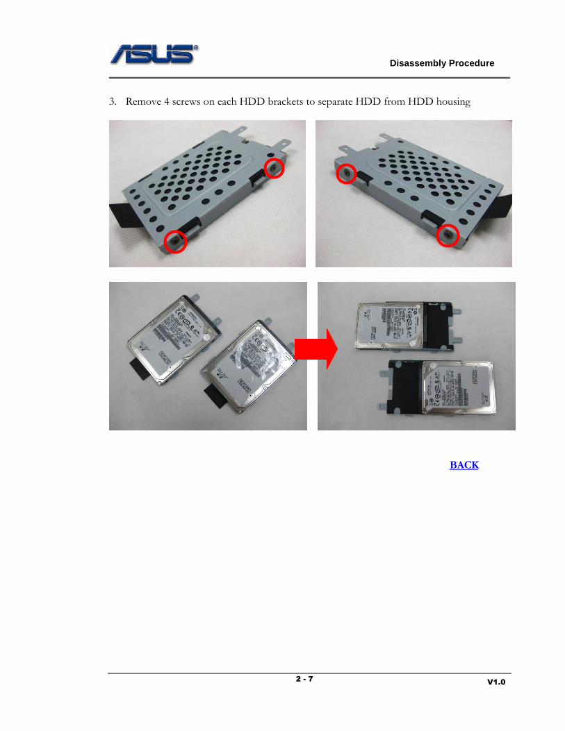
3. Remove 4 screws on each HDD brackets to separate HDD from HDD housing
BACK
Disassembly Procedure
V1.0 2 - 8
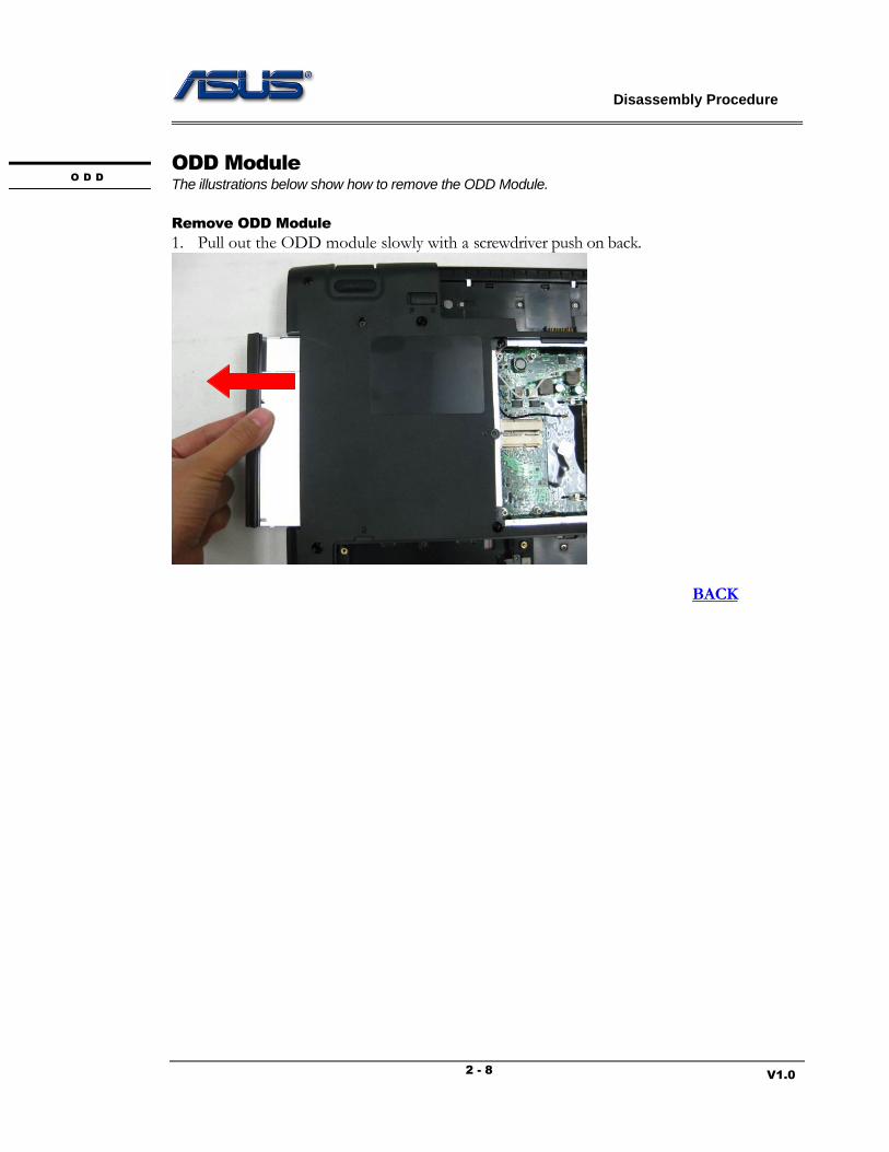
ODD Module
The illustrations below show how to remove the ODD Module.
Remove ODD Module
1. Pull out the ODD module slowly with a screwdriver push on back.
BACK
O D D
Disassembly Procedure
V1.0 2 - 9
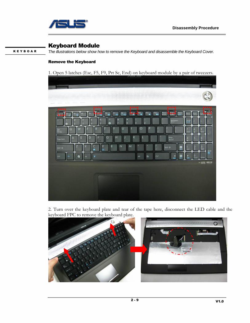
Keyboard Module
The illustrations below show how to remove the Keyboard and disassemble the Keyboard Cover.
Remove the Keyboard
1. Open 5 latches (Esc, F5, F9, Prt Sc, End) on keyboard module by a pair of tweezers.
2. Turn over the keyboard plate and tear of the tape here, disconnect the LED cable and the keyboard FPC to remove the keyboard plate.
K E Y B O A R
Disassembly Procedure
V1.0 2 - 10
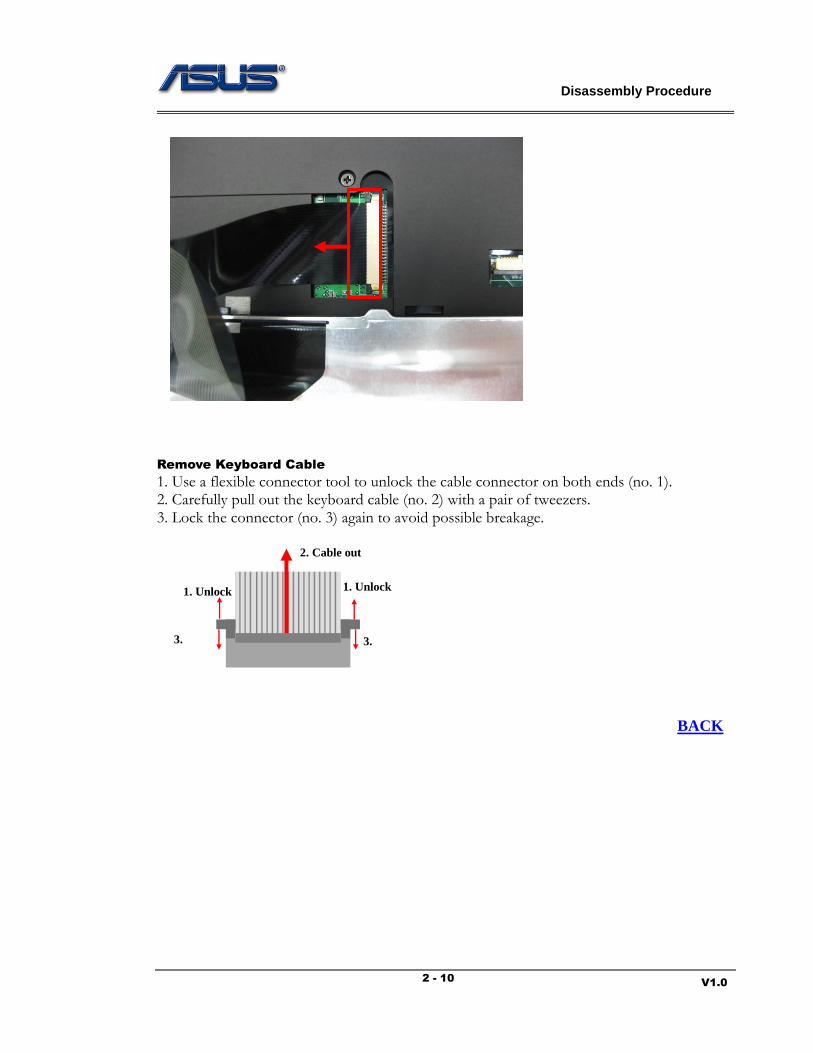
Remove Keyboard Cable
1. Use a flexible connector tool to unlock the cable connector on both ends (no. 1). 2. Carefully pull out the keyboard cable (no. 2) with a pair of tweezers. 3. Lock the connector (no. 3) again to avoid possible breakage.
BACK
1. Unlock
2. Cable out
3.
Lock
1. Unlock
3.
Lock
Disassembly Procedure
V1.0 2 - 11
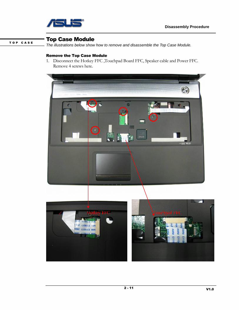
Top Case Module
The illustrations below show how to remove and disassemble the Top Case Module.
Remove the Top Case Module
1. Disconnect the Hotkey FFC ,Touchpad Board FFC, Speaker cable and Power FFC. Remove 4 screws here.
T O P C A S E
Touchpad FFC Hotkey FFC
Disassembly Procedure
V1.0 2 - 12
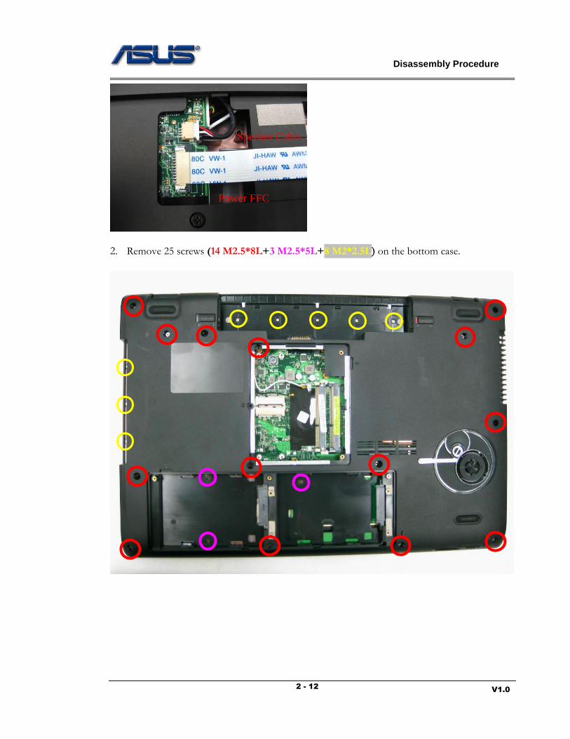
2. Remove 25 screws (14 M2.5*8L+3 M2.5*5L+8 M2*2.5L) on the bottom case.
Speaker Cable
Power FFC
Disassembly Procedure
V1.0 2 - 13
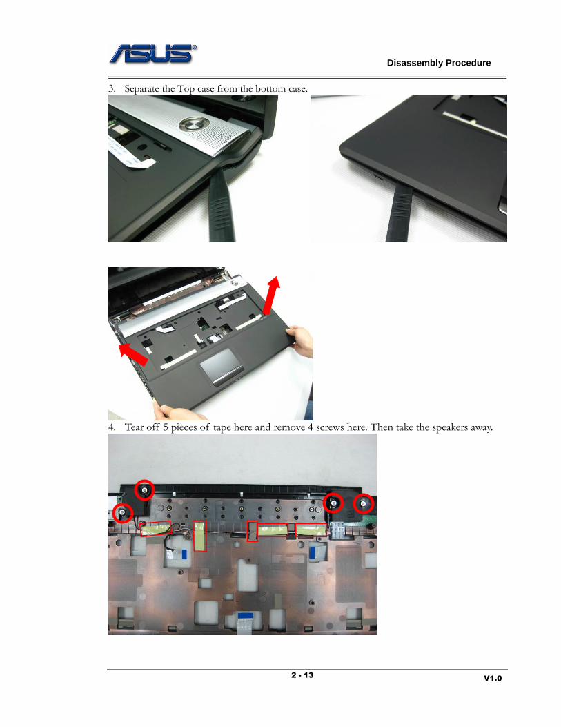
3. Separate the Top case from the bottom case.
4. Tear off 5 pieces of tape here and remove 4 screws here. Then take the speakers away.

Disassembly Procedure
V1.0 2 - 14
2. Reel off the power FFC and disconnect it with the power switch board.
Remove 3 screws here and take the power switch board away.

Disassembly Procedure
V1.0 2 - 15
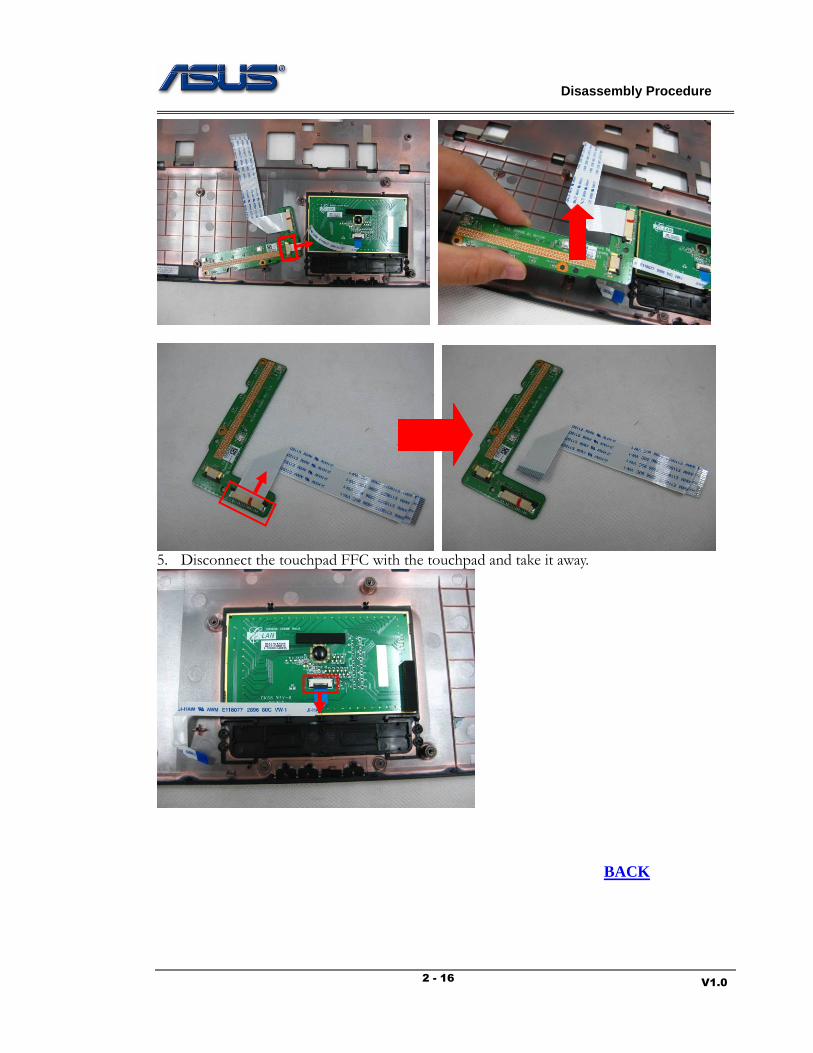
3. Reel off the hotkey FFC and disconnect it with the hotkey board. Remove 2 screws here and take the hotkey board away.
4. Tear off the tape here and remove 2 screws here, then turn over the touchpad board.
Then disconnect the touchpad FFC and remove the touchpad board. Disconnect the touchpad board FFC with the touchpad board.
Disassembly Procedure
V1.0 2 - 16
5. Disconnect the touchpad FFC with the touchpad and take it away.
BACK
Disassembly Procedure
V1.0 2 - 17
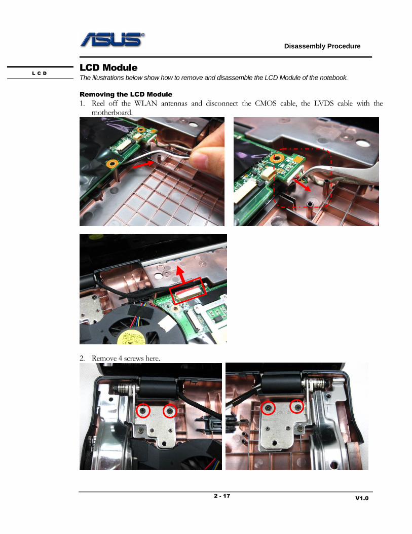
LCD Module
The illustrations below show how to remove and disassemble the LCD Module of the notebook.
Removing the LCD Module
1. Reel off the WLAN antennas and disconnect the CMOS cable, the LVDS cable with the motherboard.
2. Remove 4 screws here.
L C D
Disassembly Procedure
V1.0 2 - 18
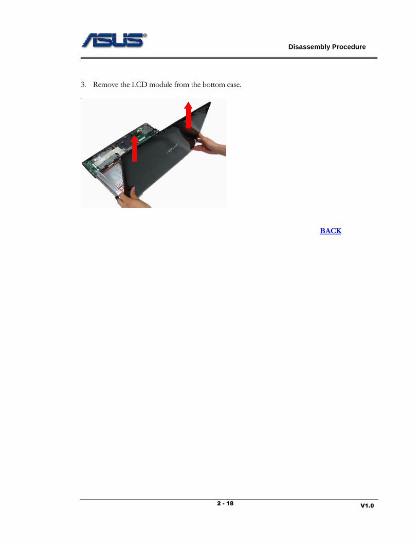
3. Remove the LCD module from the bottom case.
BACK
Disassembly Procedure
V1.0 2 - 19
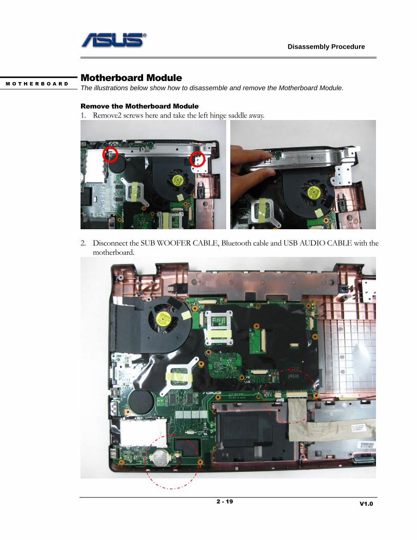
Motherboard Module
The illustrations below show how to disassemble and remove the Motherboard Module.
Remove the Motherboard Module
1. Remove2 screws here and take the left hinge saddle away.
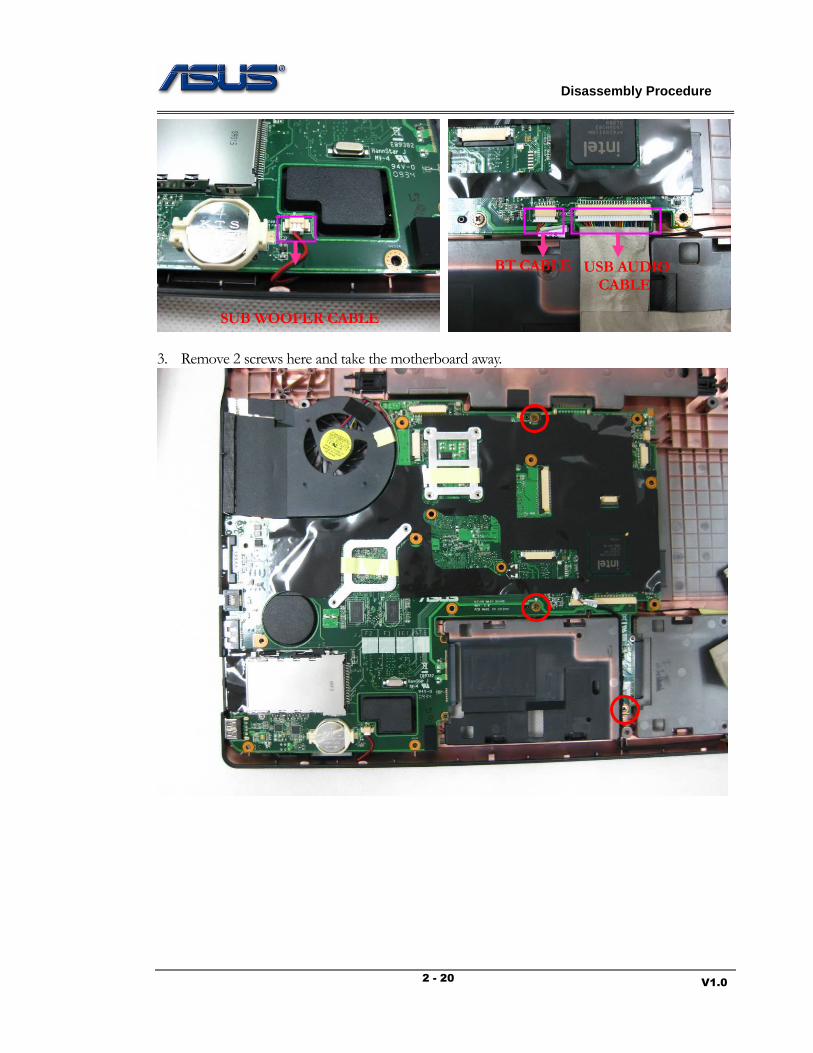
2. Disconnect the SUB WOOFER CABLE, Bluetooth cable and USB AUDIO CABLE with the
motherboard.
M O T H E R B O A R D
Disassembly Procedure
V1.0 2 - 20
3. Remove 2 screws here and take the motherboard away.
SUB WOOFER CABLE
BT CABLE
USB AUDIO
CABLE
Disassembly Procedure
V1.0 2 - 21
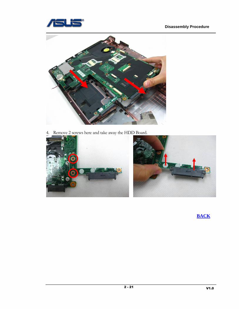
4. Remove 2 screws here and take away the HDD Board.
BACK

Disassembly Procedure
V1.0 2 - 22
CPU Module
The illustrations below show how to remove the CPU module.
Remove the CPU Module
1. Disconnect the fan cable.
2. Remove 8 screws here and take the CPU thermal module away.
3. Turn the non-removable screw here 180 degrees counter-clockwise to loosen the CPU.
C P U
Disassembly Procedure
V1.0 2 - 23
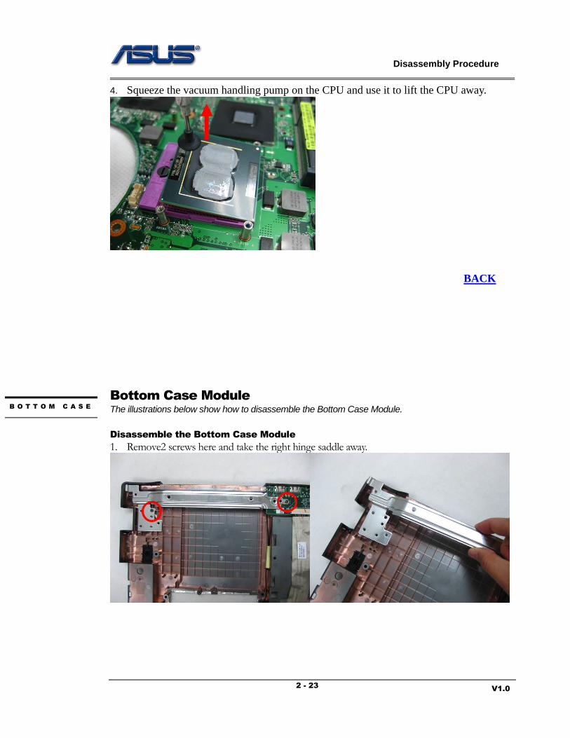
4. Squeeze the vacuum handling pump on the CPU and use it to lift the CPU away.
BACK
Bottom Case Module
The illustrations below show how to disassemble the Bottom Case Module.
Disassemble the Bottom Case Module
1. Remove2 screws here and take the right hinge saddle away.
B O T T O M C A S E

Disassembly Procedure
V1.0 2 - 24
2. Tear off the tape here and take the AUDIO Board away. Then disconnect the USB AUDIO CABLE with it.
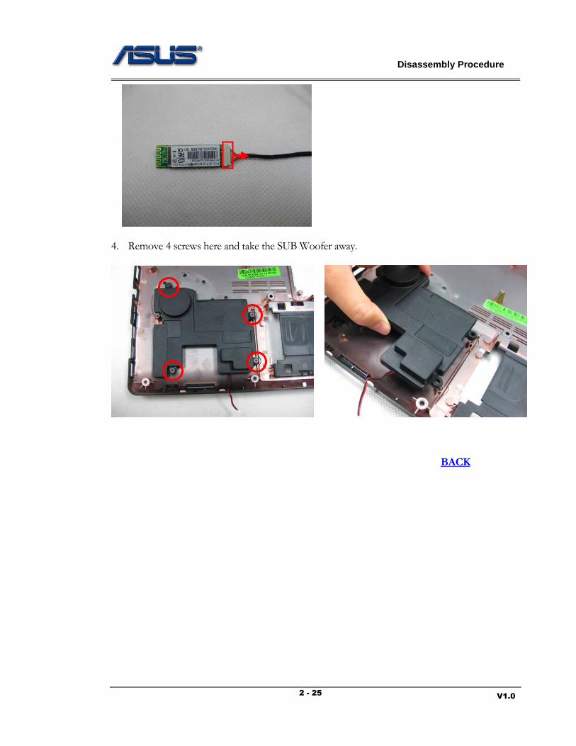
3. Remove the Bluetooth module form the bottom case, and disconnect the Bluetooth cable.
Disassembly Procedure
V1.0 2 - 25
4. Remove 4 screws here and take the SUB Woofer away.
BACK