discontinued mechanical models information & service bulletins · information & service...
TRANSCRIPT

2004 Edition
Manual P/N 02980507(01/04)
© 2004 Alamo Group Inc.
Alamo IndustrialP. O. Drawer 549Seguin, Texas 78155830-372-3551
INFORMATION& SERVICEBULLETINS
DISCONTINUEDMECHANICAL
MODELS


© 2004 Alamo Group Inc.
INFORMATION & SERVICEBULLETINS INTRODUCTION
This Book is divided into two Sections
Section One - Technical Information Bulletins
1. Technical Information Bulletins: Information Bulletins are listed by Bulletin Number (Date).Example the oldest Bulletin will be listed first and the most recent bulletin will be listed last.Bulletin No. 021002 = first & second digits are the month, the third & fourth digits are the dayof the month and the fifth & sixth digits are the year this means, the bulletin was written on Feb,10, 2002. If more than one bulletin was written on that day the a dash with a number will added,example -1, -2 etc.
2. Authorize Repairs: Technical Information Bulletins do not authorize any repairs to be madeunder warranty or any other circumstance unless specifically instructed to do so.
3. Bulletin Reference: Some Technical Information Bulletins will refer to the correspondingService Bulletins for repairs and some are for information only.
4. Bulletin Instructions: Technical Information Bulletins should have all the instructions as towhat you need, but may not have all the information needed to make an installation complete.In some cases it may be required to refer to other manuals for more complete information, thisshould be suggested in the Technical Information Bulletin.
5. All Technical Information Bulletins printed in this Manual will void any previously printed Bulletins.Any changes in these bulletins are the final version as of the date of this manual.
Section Two - Service Bulletins
1. Service Bulletin No: Service Bulletins are listed by Bulletin Number (Date). Example theoldest Bulletin will be listed first and the most recent bulletin will be listed last. Bulletin No. 021004= first & second digits are the Year, the third & fourth digits are the day of the month and the fifth& sixth digits are the month, this means the bulletin was written on Apr, 10, 2002. If more thanone bulletin was written on that day the a dash with a number will added, example -1, -2 etc.
2. Repairs: Service Bulletins are intended to authorize only the repairs listed on It to be madeunder warranty or any other circumstance unless specifically instructed to do so.
3. Parts: This is the Rate at which compensation will be allowed under warranty for repair parts.4. Labor: This is the amount of labor (hours) that are allowed to make this repair under warranty.5. Parts Disposition: Service Bulletins list the disposition of any parts that are removed during the
repair. If listed removed parts must be held awaiting return to factory if instructed to do so.6. Termination Date: Service bulletins show a termination date, this is the date that the Bulletin
will be discontinued, Any repairs must be made and all warranty applications filed by the listeddate.
7. All Service Bulletins printed in this Manual will void any previously printed Bulletins. Anychanges in these bulletins are the final version as of the date of this manual.

© 2004 Alamo Group Inc.
INDEXDISCONTINUED MECHANICAL
MODELSSection 1
Technical Information Bulletins
INDEX - 1
Bulletin No. (Old No.) Page Date Description
----------......................... 1-1................-----------.... Information Bulletins Introduction092694.. (940014A)...... 1-2................09/26/94.... Gauge Wheel Bearing Conversion (GF)101494.. (940018).........1-3................10/14/94.... Spindle Adjustment (GF)040896.......................... 1-4................04/08/96.... Hydraulic Cylinder Leaking Oil (All)050697.. (050697A)...... 1-5................05/06/97.... Springless Slip Cutch Adjustment (All)050697.. (043097R)...... 1-5................05/06/97.... Springless Slip Cutch Adjustment (All)102398.......................... 1-6................10/23/98.... Clutch Disk Lining, other than OEM (All)112498.......................... 1-7................11/24/98.... Three Point Lift Hitch Identification (All)
© 2004 Alamo Group Inc. INDEX - 2
INDEXDISCONTINUED MECHANICAL
MODELSSection 2
Service BulletinsBulletin No. (Old No.) Page Date Description
----------......................... 2-1............... -----------.... Service Bulletin Introduction850102.. (85-002)......... 2-2............... 02/01/85.... Height Adjustment (TK80, TK90, TK101)852207.. (85-006)......... 2-3............... 07/22/85.... Gearbox Flex Coupler (TK80, TK90, TK101)862705.. (86-003)......... 2-4............... 05/27/86.... Blade Bar Timing *TK90, TK101)861906.. (86-004)......... 2-5............... 06/19/86.... Replacement Gearbox Available (TK90)860107.. (86-005)......... 2-6............... 07/01/86.... Center section Deck Reinforcement (TK15-IV)861108.. (86-006)......... 2-7............... 08/11/86.... Slip Clutch Adjustment (TK15, TK15HD)860310.. (86-007)......... 2-8............... 10/03/86.... Blade Recall (TK15, TK15HD)860610.. (86-008)......... 2-9............... 10/06/86.... Center Deck Welding Required (TK20-IV)872206.. (87-002)......... 2-10............. 06/22/87.... Output Shaft Parts Inter-Change (TK90, TK100)870311.. (87-003)......... 2-11............. 11/03/87.... Hub Cap Retainer (All Pull Type)870312.. (87-004)......... 2-12............. 12/03/87.... Wing Driveline Installation (TK15-IV, TK20-IV)881101.. (88-001)......... 2-13............. 01/11/88.... Wing Driveline Universal Joint Yoke (TK15-IVD)881002.. (88-002)......... 2-14............. 02/10/88... Gearbox Oil Leak (TK15-IVD)891508.. (89-010)......... 2-15............. 08/15/89... Cutter Shaft Re-Design (T-48)902404.. (90-005)......... 2-16............. 04/24/90... Tail Wheel Modification (BD80)902205.. (90-007)......... 2-17............. 05/22/90... Spindle Mount & Tail Whl Brkt Modification (BD80)900106.. (90-008)......... 2-18............. 06/01/90... Spindle Lubrication Instructions (BD80)901106.. (90-009)......... 2-19............. 06/11/90... Jack Shaft Length Adjustment (A310, A210)900308.. (90-011)......... 2-20............. 08/03/90... Center Gearbox Replacement (A310, A210)900908.. (90-013)......... 2-21............. 08/09/90... Center Outer Axle Replacement (A315, A415)902210.. (90-018)......... 2-22............. 10/22/90... Jack Shaft support Modification (A315, A210)912708.. (91-005)......... 2-23............. 10/30/91... Gearbox Re-Design (A415, A315, AG60, AG72)922002.. (92-002)......... 2-24............. 02/20/92... Aircraft Tire & Wheel Operating Procedure (All)922905.. (92-008)......... 2-25............. 05/29/92... Slide Yoke Q.D. Collar Modification (AG15-IV
A415, AG84B, A315, A310, AG20, AG10)932903.. (93-001)......... 2-26..............03/29/93... Tires, Blades & Roller Update (GF)930204-1 (93-002)....... 2-27..............04/02/93... Blade Stiffener Bar (GF)930204-2 (93-005)....... 2-28..............04/02/93.... Front Roller & Bearing Upgrade (GF)930207.. (93-007)......... 2-29..............07/02/93.... Rear Lift Chains & Wing Transport Bar (GF)942501.. (940003).........2-30..............01/25/94.... Spindle Upgrade (GF)951704.. (950005).........2-31..............04/17/95.... Gauge Wheel Re-Location (GF)971612.. (970011A)...... 2-32..............12/16/97... Coil Spring Kit For Slip Clutch (All)981704.. (980001A)...... 2-33..............04/17/98... Blade Recall (AG72, AG72B, AG60, AG60B, AG15)002112.. (122100A)...... 2-34..............12/21/00... Blade Recall (All)011704.. (041701B)...... 2-36..............04/17/01... Blade Recall, Second Notice (All)

© 2004 Alamo Group Inc.
NOTES

© 2004 Alamo Group Inc. 1-1
MECHANICAL DISCONTINUED MODELS
SECTION 1
TECHNICALINFORMATION
BULLETINS
(This Book is divided into two Sections)
Section One - Technical Information Bulletins
1. Technical Information Bulletins: Information Bulletins are listed by Bulletin Number (Date).Example the oldest Bulletin will be listed first and the most recent bulletin will be listed last.Bulletin No. 021002 = first & second digits are the month, the third & fourth digits are the dayof the month and the fifth & sixth digits are the year this means, the bulletin was written on Feb,10, 2002. If more than one bulletin was written on that day the a dash with a number will added,example -1, -2 etc.
2. Authorize Repairs: Technical Information Bulletins do not authorize any repairs to be madeunder warranty or any other circumstance unless specifically instructed to do so.
3. Bulletin Reference: Some Technical Information Bulletins will refer to the correspondingService Bulletins for repairs and some are for information only.
4. Bulletin Instructions: Technical Information Bulletins should have all the instructions as towhat you need, but may not have all the information needed to make an installation complete.In some cases it may be required to refer to other manuals for more complete information, thisshould be suggested in the Technical Information Bulletin.
5. All Technical Information Bulletins printed in this Manual will void any previously printed Bulletins Any changes in these bulletins are the final version as of the date of this manual.
© 2004 Alamo Group Inc. 1-2
MECHANICAL DISCONTINUED MODELS
TECHNICAL INFORMATION BULLETIN No. 092694Alamo Industrial ™ Technical Services Department
1502 East WalnutSeguin, Texas 78155
830-372-2708
Models: Grass Flex Date:Sep. 26, 1994
Bulletin No:092694(old 940014A)
This document does not authorize the repair or replacement of parts under warranty
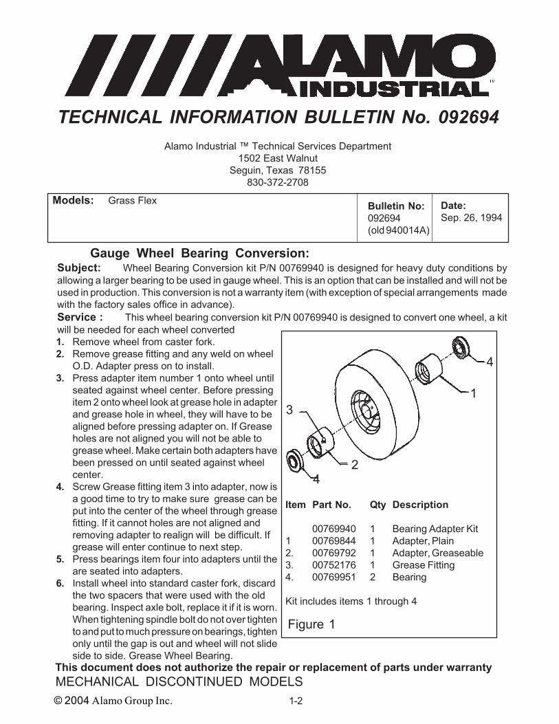
Gauge Wheel Bearing Conversion:Subject: Wheel Bearing Conversion kit P/N 00769940 is designed for heavy duty conditions byallowing a larger bearing to be used in gauge wheel. This is an option that can be installed and will not beused in production. This conversion is not a warranty item (with exception of special arrangements madewith the factory sales office in advance).Service : This wheel bearing conversion kit P/N 00769940 is designed to convert one wheel, a kitwill be needed for each wheel converted1. Remove wheel from caster fork.2. Remove grease fitting and any weld on wheel
O.D. Adapter press on to install.3. Press adapter item number 1 onto wheel until
seated against wheel center. Before pressingitem 2 onto wheel look at grease hole in adapterand grease hole in wheel, they will have to bealigned before pressing adapter on. If Greaseholes are not aligned you will not be able togrease wheel. Make certain both adapters havebeen pressed on until seated against wheelcenter.
4. Screw Grease fitting item 3 into adapter, now isa good time to try to make sure grease can beput into the center of the wheel through greasefitting. If it cannot holes are not aligned andremoving adapter to realign will be difficult. Ifgrease will enter continue to next step.
5. Press bearings item four into adapters until theare seated into adapters.
6. Install wheel into standard caster fork, discardthe two spacers that were used with the oldbearing. Inspect axle bolt, replace it if it is worn.When tightening spindle bolt do not over tightento and put to much pressure on bearings, tightenonly until the gap is out and wheel will not slideside to side. Grease Wheel Bearing.
1
2
3
4
4
Item Part No. Qty Description
00769940 1 Bearing Adapter Kit1 00769844 1 Adapter, Plain2. 00769792 1 Adapter, Greaseable3. 00752176 1 Grease Fitting4. 00769951 2 Bearing
Kit includes items 1 through 4
Figure 1
© 2004 Alamo Group Inc. 1-3
MECHANICAL DISCONTINUED MODELS
TECHNICAL INFORMATION BULLETIN No. 101494Alamo Industrial ™ Technical Services Department
1502 East WalnutSeguin, Texas 78155
830-372-2708
Models: Grass Flex Date:Oct. 14, 1994
Bulletin No:101494(old # 940018)
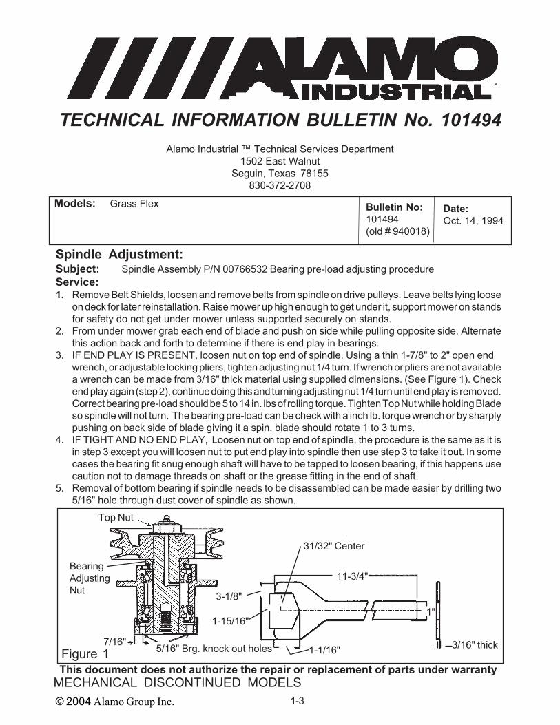
Spindle Adjustment:Subject: Spindle Assembly P/N 00766532 Bearing pre-load adjusting procedureService:1. Remove Belt Shields, loosen and remove belts from spindle on drive pulleys. Leave belts lying loose
on deck for later reinstallation. Raise mower up high enough to get under it, support mower on standsfor safety do not get under mower unless supported securely on stands.
2. From under mower grab each end of blade and push on side while pulling opposite side. Alternatethis action back and forth to determine if there is end play in bearings.
3. IF END PLAY IS PRESENT, loosen nut on top end of spindle. Using a thin 1-7/8" to 2" open endwrench, or adjustable locking pliers, tighten adjusting nut 1/4 turn. If wrench or pliers are not availablea wrench can be made from 3/16" thick material using supplied dimensions. (See Figure 1). Checkend play again (step 2), continue doing this and turning adjusting nut 1/4 turn until end play is removed.Correct bearing pre-load should be 5 to 14 in. lbs of rolling torque. Tighten Top Nut while holding Bladeso spindle will not turn. The bearing pre-load can be check with a inch lb. torque wrench or by sharplypushing on back side of blade giving it a spin, blade should rotate 1 to 3 turns.
4. IF TIGHT AND NO END PLAY, Loosen nut on top end of spindle, the procedure is the same as it isin step 3 except you will loosen nut to put end play into spindle then use step 3 to take it out. In somecases the bearing fit snug enough shaft will have to be tapped to loosen bearing, if this happens usecaution not to damage threads on shaft or the grease fitting in the end of shaft.
5. Removal of bottom bearing if spindle needs to be disassembled can be made easier by drilling two5/16" hole through dust cover of spindle as shown.
This document does not authorize the repair or replacement of parts under warranty
Top Nut
BearingAdjustingNut
5/16" Brg. knock out holes7/16"
3-1/8"1"
11-3/4"
1-1/16"
1-15/16"
31/32" Center
3/16" thickFigure 1

© 2004 Alamo Group Inc. 1-4
MECHANICAL DISCONTINUED MODELS
TECHNICAL INFORMATION BULLETIN No. 040896Alamo Industrial ™ Technical Services Department
1502 East WalnutSeguin, Texas 78155
830-372-2708
Models: All Models using Single Acting Hydraulic Cylinder Date:Apr. 8, 1996
Bulletin No:040896
This document does not authorize the repair or replacement of parts under warranty
Oil Leaking from new single Acting Hydraulic Cylinders:
There have been numerous cases of the dealers and customers replacing single actinghydraulic cylinders on new machines due to oil leakage out of the vent plug in the cylinder.
In many of these instances, no defect could be found in the cylinders. Further investigationhas revealed that he manufacture of our cylinders is leaving oil in the cylinders after their testing. TheOil is left to help protect the interior of the cylinders during storage. When the cylinders are fullyactuated, they are forcing this oil out the vent plug, causing what appears to be a leaking cylinderthrough the vent plug. Even the oil is cleaned off the cylinder after testing there is enough oil still insidethe cylinder to bleed out when used.
If you have a New Cylinder that appears to be leaking from the vent plug, The oil should becleaned off and unit ran for a few days to a week to determine if the Cylinder is leaking, or if it is theoil that was left in the cylinder to protect it. It has been found that in some cases it has taken as muchas a week for this to appear that it is not leaking.
If after running and cycling the cylinder during operation and the cylinder continues to leak thenthe necessary repair should be performed.
Cylinders that are attracting dust around them is not considered to be leaking. This dustcollecting around them is considered normal.
All Cylinder that are returned as leaking will be pressure tested for leakage to determine thecondition of the Cylinder and its components.

© 2004 Alamo Group Inc. 1-5
MECHANICAL DISCONTINUED MODELS
TECHNICAL INFORMATION BULLETIN No. 050697Alamo Industrial ™ Technical Services Department
1502 East WalnutSeguin, Texas 78155
830-372-2708
Models: All Models 2 or 4 Disk Springless Design Slip Clutch Date:May 6, 1997
Bulletin No:050697(old # 050697A& # 043097R)
This document does not authorize the repair or replacement of parts under warranty
Springless Slip Clutch Adjustment Procedure:In order to avoid damage to the mower or clutch assembly, it is important that the clutches
slip when an obstacle which creates a load that is heavier than the clutch setting is encountered. Inorder to ensure that the clutches are properly set the following adjustment procedure must befollowed. Make note, step 3 must match the type clutch, 2 disk or 4 disk type.1. Loosen all of the 8 clutch adjusting bolts until they are loosely in the clutch. While you are doingthis it is a good time to inspect the clutch to make sure all the friction disk are in good condition andare not stuck to the pressure / drive plates. See the operators / parts manual for more detail.2. Gradually and evenly tighten the bolts to the correct initial setting. To achieve the properinitial setting. Gradually tighten all of the bolts in an alternating pattern (See Figure 2) until the bolthead and nut comes in contact with the clutch outer plate. Continuing tightening the nuts only untilthe point at which the bolt and nut can be rotated in the housing using 5 to 10 inch lbs. of force. Severalcycles of tightening may be necessary until this hand tight point is reached.3A. 2 Disk Clutch: If your unit uses a 2 disk clutch, use the proper size wrench to gradually tightenthe bolts in sequence (See Figure 2) from 7/8 to 1 full additional turns more to achieve the final setting3B. 4 Disk Clutch: If your unit uses a 4 disk clutch, use the proper size wrench to gradually tightenthe bolts in sequence (See Figure 2) from 1-1/8 to 1-1/4 full additional turns more to achieve the finalsetting
1
2
3
4
56
7
8
Figure 1 Figure 2

© 2004 Alamo Group Inc. 1-6
MECHANICAL DISCONTINUED MODELS
TECHNICAL INFORMATION BULLETIN No. 102398Alamo Industrial ™ Technical Services Department
1502 East WalnutSeguin, Texas 78155
830-372-2708
Models: All Models Using a Slip Clutch on Driveline Date:Oct. 23, 1998
Bulletin No:102398
This document does not authorize the repair or replacement of parts under warranty
Clutch Disk Linings, Using Will Fit Substitute :Evidence recently revealed indicates a general attitude of many dealers to provide "will fit" or
non OEM clutch disk linings as replacement parts for the Alamo Industrial standard disk lining.
Many of these substitute disk are constructed of a material which exhibits a low pH and are,therefore, acidic in nature and tend to attract moisture. These characteristics result in a mild acidicreaction or electrolysis and corrosion of the metal components. Testing has reveled that thiscorrosion will result in adhesion of the disk lining to the metal plates in as little as two weeks time. Infact , in some cases, it was required to chisel the lining from the metal plate with a hammer and chisel.
Typical modes of failure which result from this adhesion of the lining involve many mechanicalcomponent failures to mower as well as tractor.
Clutch lining exhibiting this characteristic can be identified as being dark grey or black in color,and are available from many "will fit" suppliers. The current Alamo Industrial clutch Disk lining materialis formulated with a pH of 12 which indicates a very basic or alkaline material. In addition, the materialis impregnated with brass to provide a smooth slipping characteristic and lubrication during clutchactivation. Zinc is also impregnated into the material to provide for corrosion resistance due toelectrolysis. These standard disk are identified
Figure 1
as being tan or light brown in color, and appearto be more dense in structure than the "will Fit"disks.
Warranty claims for components fail-ures when these "will fit" disk linings are used tosubstitute for Alamo Industrial replacement partswill be subject to denial pending investigationinto the use of these. If it is determine these "willfit" disk are being used all warranty on failure ofany of the drive components, Drivelines, Gear-boxes, Blade Carriers, Clutch, Clutch Compo-nents or the Tractor itself will be denied.
Friction Disk Lining

© 2004 Alamo Group Inc. 1-7
MECHANICAL DISCONTINUED MODELS
TECHNICAL INFORMATION BULLETIN No. 112498Alamo Industrial ™ Technical Services Department
1502 East WalnutSeguin, Texas 78155
830-372-2708
Models: All Three Point Lift Type Models Date:Nov. 24, 1998
Bulletin No: 112498
This document does not authorize the repair or replacement of parts under warranty
Three Point Lift Category Dimensions:
There have been numerous inquiries as to the sizes and dimensions relating to the categoryof the three point hitch. The purpose of this bulletin is to offer a quick reference.
File this information in your sales manual for reference. This information concerns the sizesof the hitches available on tractors. The term used to identify the size is "category". The categoriesare linked to the tractor horse power. The Horse power divisions overlap and some tractors are intwo categories. Cat "0" is for garden tractors, less than 20 HP. Cat "I" is for 20 to 45 HP. Cat "II" isfor 40 to 100 HP. Cat "III" is 80 to 225 HP and Cat "IV" is from 180 to 400 HP.
Cat. A-Frame Upper Pin DiaHitch Width Height Top & Btm
("A") ("B") ("C" & "D")"0" 20" 12" 5/8" & 21/32""I" 27" 18" 3/4" & 7/8""II" 32" 19" 1" & 1-1/8""III"-N 32" 22" 1-1/4" & 1-7/16""III" 38" 22" 1-1/4" & 1-7/16""IV" 46" 27" 1-3/4" & 2"
Note: There are units that will be installed withdifferent size hitch pin (item "D") than the with.This is usually done as an example, Cat I Hitchwith Cat II Pins. There is also Cat III Narrow,this is special Cat II Width with Cat 3 height.All tractors can not be made to fit a smallerCat Hitch, it depends on tractor manufactureras to whether it was designed to.
"A"
"B"
"C"
"D"Figure 1

© 2004 Alamo Group Inc. 1-8
MECHANICAL DISCONTINUED MODELS
NOTES

© 2004 Alamo Group Inc. 2-1MECHANICAL DISCONTINUED MODELS
SECTION 2
SERVICEBULLETINS
(This Book is divided into two Sections)Section Two - Service Bulletins
1. Service Bulletin No: Service Bulletins are listed by Bulletin Number (Date). Example theoldest Bulletin will be listed first and the most recent bulletin will be listed last. Bulletin No. 021004= first & second digits are the Year, the third & fourth digits are the day of the month and the fifth& sixth digits are the month, this means the bulletin was written on Apr, 10, 2002. If more thanone bulletin was written on that day the a dash with a number will added, example -1, -2 etc.
2. Repairs: Service Bulletins are intended to authorize only the repairs listed on It to be madeunder warranty or any other circumstance unless specifically instructed to do so.
3. Parts: This is the Rate at which compensation will be allowed under warranty for repair parts.4. Labor: This is the amount of labor (hours) that are allowed to make this repair under warranty.5. Parts Disposition: Service Bulletins list the disposition of any parts that are removed during the
repair. If listed removed parts must be held awaiting return to factory if instructed to do so.6. Termination Date: Service bulletins show a termination date, this is the date that the Bulletin
will be discontinued, Any repairs must be made and all warranty applications filed by the listeddate.
7. All Service Bulletins printed in this Manual will void any previously printed Bulletin. Anychanges in these bulletins are the final version as of the date of this manual.

© 2004 Alamo Group Inc. 2-2
MECHANICAL DISCONTINUED MODELS
SERVICE BULLETIN No. 850102Alamo Industrial Technical Services Department
1502 East WalnutSeguin, Texas 78155
830-372-2708
Height Adjustment :
Subject:To prevent scalping with blades for longer blade life.
Service Required:For maximum blade life, the front skid shoe should be adjusted to 1/2 the cutting height below the
blade as shown in figure 1. Example, for 6" cutting height, adjust skid to 3" below the blade or to the lowestadjustment of the skid shoe.
Models: TK-80, TK-90 & TK-101 Date:
Feb. 1, 1985
Bulletin No: 850102(Old # 85-002)
Parts:100 % at Dealer Net
Labor:.0 hr. (to be determine oncase by case)
Termination Date:May 15, 1985
Old Parts Disposition:No Parts Involved
Warranty Compensation will be provided following proper filing of warranty claim in accordance withthe Alamo Industrial Warranty Policy. Claim allowance may vary in accordance with laws governing aspecific region. Any Warranty associated with this service bulletin must be within authorized dates.
1/2 Cutting Height
Figure 1

© 2004 Alamo Group Inc. 2-3MECHANICAL DISCONTINUED MODELS
SERVICE BULLETIN No. 852207Alamo Industrial Technical Services Department
1502 East WalnutSeguin, Texas 78155
830-372-2708
Gearbox Flex Couplers, Dual Spindle Models :
Subject:Longer life for the flex couplers used between the gearboxes on dual spindle models.
Service Required:If rubber disc on the gearbox flex couplers show unusual distortion due to cutting conditions, the
following is recommended. Convert from 2 disc to a 3 disc setup.1. Remove the spacer shown (See Figure 1) saving all bolts, nuts, washers and cotter pins.2. Install an additional rubber disc P/N 00749172 & reinstall the bolts and other hardware.3. Torque bolts evenly (alternating pattern) to 50 ft lbs maximum. (See Figure 2)
Models: TK-80, TK-90 & TK-101 Date:
Jul. 22, 1985
Bulletin No: 852207(Old # 85-006)
Parts:100 % at Dealer Net
Labor:.0 hr. (to be determine oncase by case)
Termination Date:Sep 30, 1985
Old Parts Disposition:No Parts Involved
Warranty Compensation will be provided following proper filing of warranty claim in accordance withthe Alamo Industrial Warranty Policy. Claim allowance may vary in accordance with laws governing aspecific region. Any Warranty associated with this service bulletin must be within authorized dates.
Figure 1 Figure 2Remove Spacer
Remove Spacer
2 Disc Coupler 3 Disc Coupler
Install Third Disc
Install Third Disc

© 2004 Alamo Group Inc. 2-4
MECHANICAL DISCONTINUED MODELS
SERVICE BULLETIN No. 862705Alamo Industrial Technical Services Department
1502 East WalnutSeguin, Texas 78155
830-372-2708
Blade Bar Timing :
Subject:Blade Bar timing to eliminate Blade interference on dual spindle models. This is done to prevent
blade damage of blades hitting each other.Service Required:
Items 1 & 2 shown in figure 1 are 1/2" X 3-1/2" long grade 8 bolts and locknuts. This bolt is designedto shear when either gearbox is shock loaded. Due to blade overlap and blade rotation as shown in figure2, it is important that the blade bars be in relative position shown in figure 2, when replacing the shear boltor if the blade bars have to be reinstalled. This will prevent blade interference during blade rotation. NOTE:If the blades cannot be set as shown, it is preferred that one of the carriers be backed up (opposite rotationof cut) a maximum of 10°.
Models: TK-90 & TK-101 Date:
May 27, 1986
Bulletin No: 862705(Old # 86-003)
Parts:100 % at Dealer Net
Labor:.0 hr. (to be determine oncase by case)
Termination Date:Jul. 30, 1986
Old Parts Disposition:No Parts Involved
Warranty Compensation will be provided following proper filing of warranty claim in accordance withthe Alamo Industrial Warranty Policy. Claim allowance may vary in accordance with laws governing aspecific region. Any Warranty associated with this service bulletin must be within authorized dates.
Figure 1 Figure 2
1,2 1,2
10° Maximum retardedtiming is allowed

© 2004 Alamo Group Inc. 2-5MECHANICAL DISCONTINUED MODELS
SERVICE BULLETIN No. 861906Alamo Industrial Technical Services Department
1502 East WalnutSeguin, Texas 78155
830-372-2708
Replacement Gearbox & Blade Carrier Kit :
Subject:Gearbox and blade carrier replacement kit.
Service Required: Should you experience gearbox failures with listed serial numbers on the TK-90, Terrain King
Corporation has developed a replacement Kit P/N 00755390 that is designed to replace the failed gearboxand blade carriers. This Kit consist of 2 gearboxes and Blade Bar carriers and must be installed as a kitto insure proper operation of the unit. Serial numbers relating to this replacement must be furnished toTerrain King Corporation when ordering this kit. If gearboxes are not changed as a kit damage will result.
Serial Numbers Effected:
Models: TK-90 (See Serial Numbers Below) Date:
Jun. 19, 1986
Bulletin No: 861906(Old # 86-004)
Parts:100 % at Dealer Net
Labor:.0 hr. (to be determine oncase by case)
Termination Date:Aug. 30, 1986
Old Parts Disposition:Hold Parts for return
Warranty Compensation will be provided following proper filing of warranty claim in accordance withthe Alamo Industrial Warranty Policy. Claim allowance may vary in accordance with laws governing aspecific region. Any Warranty associated with this service bulletin must be within authorized dates.
S/N Product
42624 TK-90L42625 TK-90L42626 TK-90L42627 TK-90L42628 TK-90L42629 TK-90L42630 TK-90L42631 TK-90P42632 TK-90P42633 TK-90P42634 TK-90P42635 TK-90P42636 TK-90P
S/N Product
42637 TK-90P42845 TK-90P43521 TK-90L43536 TK-90L43558 TK-90P43582 TK-90L43582 TK-90L43611 TK-90P43612 TK-90P43613 TK-90P43614 TK-90P43615 TK-90P43616 TK-90P
S/N Product
43617 TK-90P43618 TK-90P43619 TK-90P43620 TK-90P43717 TK-90L43720 TK-90L43721 TK-90L43726 TK-90L43807 TK-90L44043 TK-90P44559 TK-90L44566 TK-90L

© 2004 Alamo Group Inc. 2-6
MECHANICAL DISCONTINUED MODELS
SERVICE BULLETIN No. 860107Alamo Industrial Technical Services Department
1502 East WalnutSeguin, Texas 78155
830-372-2708
Center Section Deck Reinforcement :
Subject:Reinforcement of center section frame. Kit P/N 00755401 will provide necessary parts to complete
this modification. To give better structural strength to the center section weldment.Service Required:
Weld a 3-1/2" X 2-1/2" X 1/4" angle to each 5" X 3" X 5/16" main angles as shown in section A-A.These angles will weld on the front lug of the wing cylinder mounting and extend forward beyond centersection gearbox. Weld a 3/4" X 3" flat bar on the center angle as shown in section B-B from the front ofaxle lug to the cross angle at the rear of the gearbox.
Models: TK15-IV Date:
Jul. 1, 1986
Bulletin No: 860107(Old # 86-005)
Parts:100 % at Dealer Net
Labor:.0 hr. (to be determine oncase by case)
Termination Date:Sep. 30, 1986
Old Parts Disposition:No Parts Involved to return
Warranty Compensation will be provided following proper filing of warranty claim in accordance withthe Alamo Industrial Warranty Policy. Claim allowance may vary in accordance with laws governing aspecific region. Any Warranty associated with this service bulletin must be within authorized dates.
3-1/2" X 2-1/2" X 1/4" Angle
1/4 3-6Both Sides
B
B
A
A
1/4 2-4
3/4" X 3" Flat Bar
3-1/2" X 2-1/2" X 1/4" Angle
3-1/2 ref.
Sec. A - A
Sec. B - B
3/4 X 3
3-1/2 X 2-1/4 X 1/4
Figure 1
© 2004 Alamo Group Inc. 2-7MECHANICAL DISCONTINUED MODELS
SERVICE BULLETIN No. 861108Alamo Industrial Technical Services Department
1502 East WalnutSeguin, Texas 78155
830-372-2708
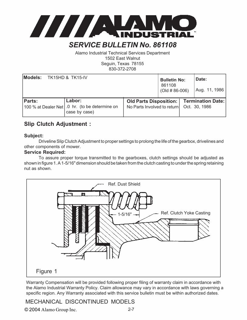
Slip Clutch Adjustment :
Subject:Driveline Slip Clutch Adjustment to proper settings to prolong the life of the gearbox, drivelines and
other components of mower.Service Required:
To assure proper torque transmitted to the gearboxes, clutch settings should be adjusted asshown in figure 1. A 1-5/16" dimension should be taken from the clutch casting to under the spring retainingnut as shown.
Models: TK15HD & TK15-IV Date:
Aug. 11, 1986
Bulletin No: 861108(Old # 86-006)
Parts:100 % at Dealer Net
Labor:.0 hr. (to be determine oncase by case)
Termination Date:Oct. 30, 1986
Old Parts Disposition:No Parts Involved to return
Warranty Compensation will be provided following proper filing of warranty claim in accordance withthe Alamo Industrial Warranty Policy. Claim allowance may vary in accordance with laws governing aspecific region. Any Warranty associated with this service bulletin must be within authorized dates.
Figure 1
Ref. Dust Shield
1-5/16" Ref. Clutch Yoke Casting

© 2004 Alamo Group Inc. 2-8
MECHANICAL DISCONTINUED MODELS
SERVICE BULLETIN No. 860310Alamo Industrial Technical Services Department
1502 East WalnutSeguin, Texas 78155
830-372-2708
Blade Recall :
Subject:Blades P/N 00750787 and 00750788 Recall. Blades with rounded ends replacement.
Service Required:Blades shipped with rounded ends (See Figure 2) do not meet specifications. These blades are
NOT marked with P/N 00750787 and 00750788 at the end (See Figure 2). They are being replaced withblades that will have a square end and have the P/N stamped into them (See Figure 1). Check all the bladeson current units as well as all blades in your parts inventory.
Models: TK15HD & TK15-IV Date:
Oct. 3, 1986
Bulletin No: 860310(Old # 86-007)
Parts:100 % at Dealer Net
Labor:.0 hr. (to be determine oncase by case)
Termination Date:Dec. 30, 1986
Old Parts Disposition:Hold Parts For return
Warranty Compensation will be provided following proper filing of warranty claim in accordance withthe Alamo Industrial Warranty Policy. Claim allowance may vary in accordance with laws governing aspecific region. Any Warranty associated with this service bulletin must be within authorized dates.
Figure 1 Figure 2
Part Number isStamped Here
Squared End
NO Part NumberStamped Here
Rounded End End
NewBlade
OldBlades

© 2004 Alamo Group Inc. 2-9MECHANICAL DISCONTINUED MODELS
SERVICE BULLETIN No. 860610Alamo Industrial Technical Services Department
1502 East WalnutSeguin, Texas 78155
830-372-2708
Center Deck Welding Required :
Subject:Reinforcement of TK20-IV Center Section Wing Attaching Channel due to weld failure wherechannel is welded to main deck plate (See Figure 1). To prevent structural damage due to weldfailure in this area.
Service Required:1. Re-weld with a continous weld bead along the seam where channel is attchaed to deck plate at
the outside of channel.2. At the rear of the center section where 2-1/2" X 3-1/2" X 3/8" angle is located, position item 1
(1/4" X 4" X 8" flat bar) 1/2" above the deck plate on the channel and weld to channel and angle.Install on both right and left hinge channel.
Models: TK20-IV Date:
Oct. 6, 1986
Bulletin No: 860610(Old # 86-008)
Parts:100 % at Dealer Net
Labor:.0 hr. (to be determine oncase by case)
Termination Date:Dec. 30, 1986
Old Parts Disposition:No Parts To Return
Warranty Compensation will be provided following proper filing of warranty claim in accordance withthe Alamo Industrial Warranty Policy. Claim allowance may vary in accordance with laws governing aspecific region. Any Warranty associated with this service bulletin must be within authorized dates.
1
1
3/8
1/2
Butt Weld ContinousAlong This Seam
Figure 1
3/8

© 2004 Alamo Group Inc. 2-10
MECHANICAL DISCONTINUED MODELS
SERVICE BULLETIN No. 872206Alamo Industrial Technical Services Department
1502 East WalnutSeguin, Texas 78155
830-372-2708
Gearbox Output Shaft Parts Inter-Change :
Subject:Interchangeability of parts for gearboxes. Using the long Spacer P/N 00563800 with bearing cap
P/N 00563400 and using the short spacer P/N 6710510 with bearing cap P/N 711052.Service Required:
As shown in figure 1, the long spacer (2.56" long & P/N 00563800) is used with bearing cap P/N00563400. The short spacer (2.415" long & P/N 6710510) is used with bearing cap P/N 711052. Theseparts must be used in pairs. To distinguish the difference between which measure the spacer, or look atthe Bearing cap. The Bearing cap (P/N 711052) for the long spacer has a sunken area 1/8" deep that thelower bearing sits into, the cap used with the short spacer will not. DO NOT try to mix these bearings andcaps, both will work in the same gearbox as long as the cap is used that fits the spacer.
Models: TK90 & TK100 Date:
Jun. 22, 1987
Bulletin No: 872206(Old # 87-002)
Parts:100 % at Dealer Net
Labor:.0 hr. (to be determine oncase by case)
Termination Date:Aug. 30, 1987
Old Parts Disposition:No Parts To Return
Warranty Compensation will be provided following proper filing of warranty claim in accordance withthe Alamo Industrial Warranty Policy. Claim allowance may vary in accordance with laws governing aspecific region. Any Warranty associated with this service bulletin must be within authorized dates.
Figure 1
00563400Bearing Capwith LongSpacer00563800
2.56" long 2.415" long
Bearing sits 1/8"into Bearing Cap
Bearing sits flushon Bearing Cap
711052Bearing Capwith shortSpacer6710510
© 2004 Alamo Group Inc. 2-11MECHANICAL DISCONTINUED MODELS
SERVICE BULLETIN No. 870311Alamo Industrial Technical Services Department
1502 East WalnutSeguin, Texas 78155
830-372-2708
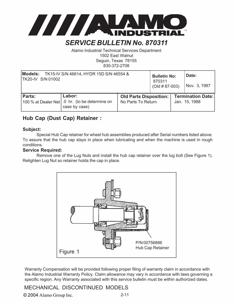
Hub Cap (Dust Cap) Retainer :
Subject:Special Hub Cap retainer for wheel hub assemblies produced after Serial numbers listed above.
To assure that the hub cap stays in place when lubricating and when the machine is used in roughconditions.Service Required:
Remove one of the Lug Nuts and install the hub cap retainer over the lug bolt (See Figure 1).Retighten Lug Nut so retainer holds the cap in place.
Models: TK15-IV S/N 46614, HYDR 15D S/N 46554 &TK20-IV S/N 01002
Date:
Nov. 3, 1987
Bulletin No: 870311(Old # 87-003)
Parts:100 % at Dealer Net
Labor:.0 hr. (to be determine oncase by case)
Termination Date:Jan. 15, 1988
Old Parts Disposition:No Parts To Return
Warranty Compensation will be provided following proper filing of warranty claim in accordance withthe Alamo Industrial Warranty Policy. Claim allowance may vary in accordance with laws governing aspecific region. Any Warranty associated with this service bulletin must be within authorized dates.
Figure 1
P/N 00756886Hub Cap Retainer

© 2004 Alamo Group Inc. 2-12
MECHANICAL DISCONTINUED MODELS
SERVICE BULLETIN No. 870312Alamo Industrial Technical Services Department
1502 East WalnutSeguin, Texas 78155
830-372-2708
Wing Driveline Installation :Subject:
Wing Driveline installation, Change in way wing drivelines are being installed. The output shaft onthe divider gearbox has 1-1/2" of spline in front of the Q.D. locking groove for the slip clutch to clamp on.This additional distance will give better support to the slip clutch and reduce the wear on the splines.Service Required:
Install the two wing drivelines with the slip clutch end mounted on the divider gearbox and the Q.D.Yoke mounted on the wing gearbox end. This is the opposite the way these were mounted in the past.
Models: TK15-IV, TK20-IV Date:
Dec. 3, 1987
Bulletin No: 870312(Old # 87-004)
Parts:100 % at Dealer Net
Labor:.0 hr. (to be determine oncase by case)
Termination Date:Feb. 28, 1988
Old Parts Disposition:No Parts To Return
Warranty Compensation will be provided following proper filing of warranty claim in accordance withthe Alamo Industrial Warranty Policy. Claim allowance may vary in accordance with laws governing aspecific region. Any Warranty associated with this service bulletin must be within authorized dates.
Figure 1
Install Drivelines with theslip clutch mounted onthe divider gearboxeswith the 1-3/8 Splines

© 2004 Alamo Group Inc. 2-13MECHANICAL DISCONTINUED MODELS
SERVICE BULLETIN No. 881101Alamo Industrial Technical Services Department
1502 East WalnutSeguin, Texas 78155
830-372-2708
Wing Driveline Yoke Inspection :
Subject:Cat IV Series 6 (35R Rating) wing driveline yokr and cross repair kit (universal joint), consisting of:
(1) 00752883 Q.D. Yoke, (1) 00754153 Inner Yoke and (1) 00752896 Cross Journal Set (universal joint).Service Required:
Our supplier has found that some of the yoke bearing cup diameters have been machined largerthan specified. Please examine your drivelines as follows.
Disconnect the 1-3/8" X 6 Spline Q.D. Yoke from the divider gearbox, Swivel the outer yoke on thecross bearing journal while observing the cup in the yoke ear. The cross bearing cup should not moveinside the yoke ear. it should be a press fit and move with the yoke ear. If the Cup moves inside the yokeear the yoke will need to be replaced. Order repair kit P/N 00757131.
Models: TK15-IVD Date:
Jan. 11, 1988
Bulletin No: 881101(Old # 88-001)
Parts:100 % at Dealer Net
Labor:.0 hr. (to be determine oncase by case)
Termination Date:Mar. 30, 1988
Old Parts Disposition:No Parts To Return
Warranty Compensation will be provided following proper filing of warranty claim in accordance withthe Alamo Industrial Warranty Policy. Claim allowance may vary in accordance with laws governing aspecific region. Any Warranty associated with this service bulletin must be within authorized dates.
Figure 1
This cup should rotate with theQ.D yoke ear when it is rotated.

© 2004 Alamo Group Inc. 2-14
MECHANICAL DISCONTINUED MODELS
SERVICE BULLETIN No. 881002Alamo Industrial Technical Services Department
1502 East WalnutSeguin, Texas 78155
830-372-2708
Gearbox Oil Level For TK15-IV :
Subject:Oil level for the gearboxes (except Divider Gearbox) on the TK15-IVD with the Gearboxes that
have the square bolt on top cover. Some of the gearboxes on the TK15IVD did not have enough oil addedat the factory to bring them up to the oil level plug after the oil drained into the lower bearing cavity.
Models: TK15-IVD Date:
Feb. 10, 1988
Bulletin No: 881002(Old # 88-002)
Parts:100 % at Dealer Net
Labor:.0 hr. (to be determine oncase by case)
Termination Date:Apr. 30, 1988
Old Parts Disposition:No Parts To Return
Warranty Compensation will be provided following proper filing of warranty claim in accordance withthe Alamo Industrial Warranty Policy. Claim allowance may vary in accordance with laws governing aspecific region. Any Warranty associated with this service bulletin must be within authorized dates.
Figure 1
Service Required:Check the oil level of all the
TK15-IVD gearboxes prior to operatingthe machines. Let the wing down to thehorizontal position and allow the oil inthe wing gearboxes to drain into thelower bearing cavity. Add oil until the oilreaches the oil level plug at the rear ofthe gearbox (See Figure 1).
OilLevelPlug
Oil Fill Plug
This Gearbox has asquare bolt on topcover.

© 2004 Alamo Group Inc. 2-15MECHANICAL DISCONTINUED MODELS
SERVICE BULLETIN No. 891508Alamo Industrial Technical Services Department
1502 East WalnutSeguin, Texas 78155
830-372-2708
Cutter Shaft Change :
Subject:Cuttershaft Size increase. The cutter shaft diameter has been increased from 1-3/4" OD tube
to 2" OD tube. This will reduce vibration at high RPM due to flex in cuttershaft.Service Required:
The complete cuttershaft (old P/N 106118 a 1-3/4" dia.) is different, the new cuttershaft (New P/N 106743 a 2" dia) also will use different clips to hold the blades. The old clip (P/N 101992) will have tobe replaced with the new clip (P/N 101017) which is shorter. Special Note: DO NOT use the old clip onthe new (2") cuttershaft, Knives could hit deck at high RPM.
Models: T-48 Flail Date:
Aug. 15, 1989
Bulletin No: 891508(Old # 89-010)
Parts:100 % at Dealer Net
Labor:.0 hr. (to be determine oncase by case)
Termination Date:Oct. 30, 1989
Old Parts Disposition:No Parts To Return
Warranty Compensation will be provided following proper filing of warranty claim in accordance withthe Alamo Industrial Warranty Policy. Claim allowance may vary in accordance with laws governing aspecific region. Any Warranty associated with this service bulletin must be within authorized dates.
Old Clip New Clip
P/N 101992 P/N 101017
3/4"7/8"
This Clip usedon 1-3/4" cuttershaft only
This Clip usedon 2" cuttershaft only
Cuter Shaft Diameter increased from 1-3/4" to 2"
Figure 1

© 2004 Alamo Group Inc. 2-16
MECHANICAL DISCONTINUED MODELS
SERVICE BULLETIN No. 902404Alamo Industrial Technical Services Department
1502 East WalnutSeguin, Texas 78155
830-372-2708
Tail Wheel Adjustment Modification :
Subject:The Single Tail Wheel on the BD80 offset 3 point lift type mowers would not stay in adjustment
at certain heights. This modification kit will maintain the Tail Wheel cutting height.Service Required:
To install the kit raise the mower until the tail wheel clears the ground. Loosen the (4) bolts thathold the tail wheel in place, allowing the tail wheel to touch the ground. Remove the "U" adjustment bracketand discard. Bolt the two new adjusting brackets , one on each side of tail wheel beam. The single holein the brackets will be up and toward the front of the mower. Bolt the two adjusting Straps (existing Parts)to the top hole while inserting the busing between the new brackets. Set the mower to the desired cuttingheight and tighten the four bolts that clamp the brackets to the tail wheel beam.
Models: BD80 Offset Lift Type Date:
Apr. 24, 1990
Bulletin No: 902404(Old # 90-005)
Parts:100 % at Dealer Net
Labor:0.5 hr. At Dealer RegisteredLabor Rate
Termination Date:Jun. 30, 1990
Old Parts Disposition:Discard old parts.
Warranty Compensation will be provided following proper filing of warranty claim in accordance withthe Alamo Industrial Warranty Policy. Claim allowance may vary in accordance with laws governing aspecific region. Any Warranty associated with this service bulletin must be within authorized dates.
Figure 1
1
2
3
45
67
8
910 4
2
4
Item Part No. Qty Description
1. 00758003 1 Tail Wheel Tube2. 10406000 3 Bolt3.* 00750311 4 Bolt4.* 00695100 8 Locknut5.* 02845800 1 Bolt6. B742023 1 Caster Wheel Asy.7.* 00759983 2 Adjustment Bracket8. 00757927 2 Bar9. 361129 2 Bushing10.* 671075 1 Spacer
© 2004 Alamo Group Inc. 2-17MECHANICAL DISCONTINUED MODELS
SERVICE BULLETIN No. 902205Alamo Industrial Technical Services Department
1502 East WalnutSeguin, Texas 78155
830-372-2708
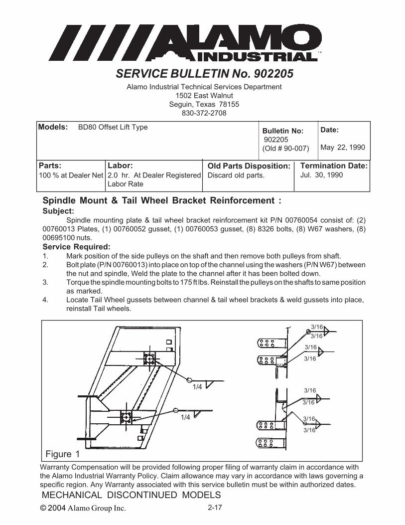
Spindle Mount & Tail Wheel Bracket Reinforcement :Subject:
Spindle mounting plate & tail wheel bracket reinforcement kit P/N 00760054 consist of: (2)00760013 Plates, (1) 00760052 gusset, (1) 00760053 gusset, (8) 8326 bolts, (8) W67 washers, (8)00695100 nuts.Service Required:1. Mark position of the side pulleys on the shaft and then remove both pulleys from shaft.2. Bolt plate (P/N 00760013) into place on top of the channel using the washers (P/N W67) between
the nut and spindle, Weld the plate to the channel after it has been bolted down.3. Torque the spindle mounting bolts to 175 ft lbs. Reinstall the pulleys on the shafts to same position
as marked.4. Locate Tail Wheel gussets between channel & tail wheel brackets & weld gussets into place,
reinstall Tail wheels.
Models: BD80 Offset Lift Type Date:
May 22, 1990
Bulletin No: 902205(Old # 90-007)
Parts:100 % at Dealer Net
Labor:2.0 hr. At Dealer RegisteredLabor Rate
Termination Date:Jul. 30, 1990
Old Parts Disposition:Discard old parts.
Warranty Compensation will be provided following proper filing of warranty claim in accordance withthe Alamo Industrial Warranty Policy. Claim allowance may vary in accordance with laws governing aspecific region. Any Warranty associated with this service bulletin must be within authorized dates.
Figure 1
3/16
1/4
1/4
3/16
3/16
3/16
3/16
3/16
3/163/16

© 2004 Alamo Group Inc. 2-18
MECHANICAL DISCONTINUED MODELS
SERVICE BULLETIN No. 900106Alamo Industrial Technical Services Department
1502 East WalnutSeguin, Texas 78155
830-372-2708
Spindle Lubrication Instruction :Subject:
Spindle lubrication, to ensure proper lubrication of upper spindle housing bearing.Service Required:
To ensure the proper lubrication of the upper spindle bearing, pump grease into the spindle cavityuntil the grease is forced out of the breather hole in the upper bearing cap. Rotate spindle shaft and keeppumping grease until grease is force out of breather hole. Lubricate spindle every 8 hours of operation.NOTE: Belt shields must be removed to observe breather hole. Replace shield after lubricating spindlefor safety and to prevent material build up around the belts.
Models: BD80 Pull Type , BD80 Lift Type & BD80 Offset Lift Type Date:
Jun. 1, 1990
Bulletin No: 900106(Old # 90-007)
Parts:100 % at Dealer Net
Labor:.0 hr. To be determined
Termination Date:Aug. 30, 1990
Old Parts Disposition:No Parts involved
Warranty Compensation will be provided following proper filing of warranty claim in accordance withthe Alamo Industrial Warranty Policy. Claim allowance may vary in accordance with laws governing aspecific region. Any Warranty associated with this service bulletin must be within authorized dates.
Figure 1
Breather Hole is inline with the greasefitting
Grease every 8 hoursuntil grease is forcedout of breather hole.

© 2004 Alamo Group Inc. 2-19MECHANICAL DISCONTINUED MODELS
SERVICE BULLETIN No. 901106Alamo Industrial Technical Services Department
1502 East WalnutSeguin, Texas 78155
830-372-2708
Jackshaft Length Adjustment :Subject:
Procedure for shortening the Jack Shaft to provide additional clearance for mower operation inrough terrain.Service Required:
To shorten jackshaft. (1) Remove screw from shield and release the two white clips by pushingthem inward until they release. (2) Slide the shield cone toward the splined end of the jackshaft exposingthe pinned yoke. (3) Drive the roll pin out of the yoke and tube. (4) Measure 7/8" from the end of the yokeand mark the tube. (5) Drive the tube into the yoke 7/8" to your mark. (6) Redrill the tube and install theroll pin. (7) Reassemble the shield on the driveline. Follow operating instructions for rough terrain asoutlined in your operators manual. (8) Check draw bar setting to make certain that it is adjusted to theproper distance as outline in the operators manual (also there should be a decal located on the tongueof the mower).
Models: A315, A210 Date:
Jun. 11, 1990
Bulletin No: 901106(Old # 90-009)
Parts:100 % at Dealer Net
Labor:.0 hr. No Labor Allowance
Termination Date:Aug. 30, 1990
Old Parts Disposition:No Parts involved
Warranty Compensation will be provided following proper filing of warranty claim in accordance withthe Alamo Industrial Warranty Policy. Claim allowance may vary in accordance with laws governing aspecific region. Any Warranty associated with this service bulletin must be within authorized dates.
Figure 1
7/8"7/8" Mark tube 7/8" from yoke

© 2004 Alamo Group Inc. 2-20
MECHANICAL DISCONTINUED MODELS
SERVICE BULLETIN No. 900308Alamo Industrial Technical Services Department
1502 East WalnutSeguin, Texas 78155
830-372-2708
Center Divider Gearbox Replacement:Subject:
Center gearbox replacement due to faulty shims and possible improper gear backlash settings.Each Dealer and/or retail customer with a unit involved is being notified individually as to the replacementof gearbox.Service Required:
Replace center divider gearbox with gearbox which has been rebuilt at factory. See serial numberlisted above, if you have one of these units and was not notified contact customer service dept. If gearboxhas been replaced since unit was put it in to service this change will not be required.
Models: A315 S/N 10000 to 10026 A210 S/N 10000 to 10018
Date:
Aug. 3, 1990
Bulletin No: 900308(Old # 90-011)
Parts:100 % at Dealer Net
Labor:2.0 hr. At Dealer RegisteredLabor Rate
Termination Date:Oct. 30, 1990
Old Parts Disposition:No Parts ReturnableInvolved
Warranty Compensation will be provided following proper filing of warranty claim in accordance withthe Alamo Industrial Warranty Policy. Claim allowance may vary in accordance with laws governing aspecific region. Any Warranty associated with this service bulletin must be within authorized dates.
Figure 1
Center Gearbox Assembly
Top View

© 2004 Alamo Group Inc. 2-21MECHANICAL DISCONTINUED MODELS
SERVICE BULLETIN No. 900908Alamo Industrial Technical Services Department
1502 East WalnutSeguin, Texas 78155
830-372-2708
Center Outer Axle Weldment Replacement:Subject:
Center outer axle weldments replacement. Replace outer axle welments on center axle whichcould experience failure, especially if wing axle is backed into obstruction.Service Required:
Replace center outer axle weldment P/N 00759143. The new weldment will be stronger built withreinforcement. Dealers and/or retail customers are being notified. See serial number listing above forunits effected. If you have one of these units and are not notified contact customer service. See Operator/ Parts Manual for axle part numbers.
Models: A315 S/N 10000 to 10029 A210 S/N 10000 to 10034 A415 S/N 10000 to 10004 A310 S/N 10000 to 10004
Date:
Aug. 9, 1990
Bulletin No: 900908(Old # 90-013)
Parts:100 % at Dealer Net
Labor:1.0 hr. At Dealer RegisteredLabor Rate
Termination Date:Oct. 30, 1990
Old Parts Disposition:Hold Parts for return
Warranty Compensation will be provided following proper filing of warranty claim in accordance withthe Alamo Industrial Warranty Policy. Claim allowance may vary in accordance with laws governing aspecific region. Any Warranty associated with this service bulletin must be within authorized dates.
Figure 1
00759143 Outer Axle Weldment

© 2004 Alamo Group Inc. 2-22
MECHANICAL DISCONTINUED MODELS
SERVICE BULLETIN No. 902210Alamo Industrial Technical Services Department
1502 East WalnutSeguin, Texas 78155
830-372-2708
Jackshaft Bearing Supports Update:Subject:
Jackshaft bearing support redesign. To eliminate any possibility of interference between bearingsupport assembly and driveline yoke. To identify if supports need to be changed look at the supports, thenew design will have spacers welded to it where the bearing housing slides into them. Also the new designwill have a curved bend in them as shown in figure 1.Service Required:
Replace old design bearing supports with the new style support weldments. These supports aresold as a kit P/N 00760669 which includes hardware, bolts, nuts, spacer and supports.
Models: A315 & A210 (All units shipped to date) Date:
Oct. 22, 1990
Bulletin No: 902210(Old # 90-018)
Parts:100 % at Dealer Net
Labor:1.0 hr. At Dealer RegisteredLabor Rate
Termination Date:Dec. 30, 1990
Old Parts Disposition:Hold Parts for return
Warranty Compensation will be provided following proper filing of warranty claim in accordance withthe Alamo Industrial Warranty Policy. Claim allowance may vary in accordance with laws governing aspecific region. Any Warranty associated with this service bulletin must be within authorized dates.
Figure 1
Item Part No. Qty Description
1.* 00760585 2 Support2.* 00760527 1 Spacer3.* 00001800 5 Locknut4.* 4994 1 Bolt5. 00013300 4 Bolt6. 15B800 4 Washer7. 681112 2 Bushing8. 00759868 1 Spacer9. 562142 1 Bracket10. 531116 1 Bearing11. 531111 1 Bearing Housing
* Kit P/N 00760669 includes items 1 thru 4
1
1
2
3
3
6
59
10 11
8
4
7
3

© 2004 Alamo Group Inc. 2-23MECHANICAL DISCONTINUED MODELS
SERVICE BULLETIN No. 912708Alamo Industrial Technical Services Department
1502 East WalnutSeguin, Texas 78155
830-372-2708
Gearbox Bearing Spacer Redesign:
Subject:Gearbox Bearing Spacer has been redesigned from a two piece screw together type to one piece
type. A bearing adjusting nut and tabbed locking washer has been added to the top of the output shaft.This changes the way that the output bearing pre-load is adjusted.Service Required:
There are no actual repairs authorized beyond normal warranty. If repairing a gearbox with theold two piece spacer, a kit has been developed to update the old style shaft and bearing spacer to thenew one piece type. Kit P/N 00761517, this kit will include new Output Shaft, Bearing Spacer andadjusting Nut. You will use the existing bearings, shims, spacers and bearing cap. Gearbox part numberwill not change and all other components are the same. (See Insert Sheet P/N 00761518)
Models: A415, AG60, AG60B, AG72. AG72B Date:
Aug. 27, 1991
Bulletin No: 912708(Old # 91-005)
Parts:100 % at Dealer Net
Labor:.0 hr. to be tertermined
Termination Date:Oct. 30, 1991
Old Parts Disposition:No Parts Involved
Warranty Compensation will be provided following proper filing of warranty claim in accordance withthe Alamo Industrial Warranty Policy. Claim allowance may vary in accordance with laws governing aspecific region. Any Warranty associated with this service bulletin must be within authorized dates.
1212121212121212
1212121212121212
Old style w/ 2piece bearingspacer New style w/ 1
piece bearingspacer &adjusting nut
Figure 1

© 2004 Alamo Group Inc. 2-24
MECHANICAL DISCONTINUED MODELS
SERVICE BULLETIN No. 922002Alamo Industrial Technical Services Department
1502 East WalnutSeguin, Texas 78155
830-372-2708
Aircraft Tire & Wheel Operating Procedure :
Subject:The Aircraft Tire & Wheel needs to be operated in a safe manner, the purpose of this bulletin is
to instruct on the proper and safe operation of this wheel
Service Required:Wheel inspection, operation procedures and operating limitations.
1. Maximum inflation pressure 50 psi.2. Maximum Transport Speed 20 MPH3. DO NOT mount any other type tire on
wheel supplied with the aircraft tire.4. Remove all air pressure from tire prior
to trying to dismount tire.5. Alamo replacement tube the aircraft tire
and wheel (P/N 00749700 Tire & Wheel)is Tube P/N 00720302, This is a specialtube for the aircraft tire and is not generallyavailable at most tire stores.
Parts Involved:P/N 00749700 = Aircraft Tire & Wheel
Assembly (25.5 X 8 X 1420-Ply Aircraft Tire & Wheel).
P/N 00720302 = Replacement Tube forAircraft Tire & Wheel above.
Models: All Models using Aircraft Tire & Wheel P/N 00749700 Date:
Feb. 20, 1992
Bulletin No: 922002(Old # 92-002)
Parts:100 % at Dealer Net
Labor:.0 hr. (to be determine oncase by case)
Termination Date:May 15, 1992
Old Parts Disposition:No Parts Involved
Warranty Compensation will be provided following proper filing of warranty claim in accordance withthe Alamo Industrial Warranty Policy. Claim allowance may vary in accordance with laws governing aspecific region. Any Warranty associated with this service bulletin must be within authorized dates.
Figure 1
DO NOT REMOVE theseassembly bolts beforeall air pressure hasbeen releasedfrom tire

© 2004 Alamo Group Inc. 2-25MECHANICAL DISCONTINUED MODELS
SERVICE BULLETIN No. 922905Alamo Industrial Technical Services Department
1502 East WalnutSeguin, Texas 78155
830-372-2708
Slide Yoke QD Collar Modification :
Subject:1-3/8" X 6 Spline & 1-3/8" X 21 Spline PTO Yokes which connect to the tractor. The Metal ring of
the design shown (see figure 1) must be replaced. If not replaced it could disconnect from the tractor PTOshaft.
Service Required:Remove the retaining ring (1), then remove the collar (2) and the metal ring (3). Inspect the metal
ring to determine what type is present, replace metal ring as required. Reinstall collar (2) and retaining ring(1). Make certain the locking balls are in place.
Parts Involved: (item 4 in Figure 1)Parts were sent to customers.
Models: AG15-IV, A415, AG84B (Pull Type), A310, AG20, AG10 Date:
May 29, 1992
Bulletin No: 922905(Old # 92-008)
Parts:100 % at Dealer Net
Labor:0.25 hr. At DealerRegistered Labor Rate
Termination Date:July 31, 1992
Old Parts Disposition:Discard old parts
Warranty Compensation will be provided following proper filing of warranty claim in accordance withthe Alamo Industrial Warranty Policy. Claim allowance may vary in accordance with laws governing aspecific region. Any Warranty associated with this service bulletin must be within authorized dates.
1/2" RadiusMetal Ring Designwhich must bereplaced
New Metal Ring replacementdesign with chamfer
1/8"
3/16"1 2 34
5 Item Description1 Retaining Ring2. Outer Collar3 Locking Balls4. Metal Lock Ring5. Spring
Figure 1

© 2004 Alamo Group Inc. 2-26
MECHANICAL DISCONTINUED MODELS
SERVICE BULLETIN No. 932903Alamo Industrial Technical Services Department
1502 East WalnutSeguin, Texas 78155
830-372-2708
Parts Update, Tires, Blade Washer & Bolt, Roller Brackets :
Subject:There are a number of parts that are being replaced. The parts will be shipped to the Dealer for
update without a order being placed. This update is to upgrade to latest specifications. Submit Warrantyfor labor only.
Service Required:1. Replace Mower Deck tires so bearings can be greased.2. Replace Blade Washer due to defective parts.3. Replace Roller Brackets for increased adjustment in cutting height.4. Replace Blade Retaining Bolt to update to latest specification. Detailed service information will be
sent with parts shipment.
Parts Required: (quantity shown is per mower with 3 decks)
Part No. Qty Description
00763662 12 Tire & Wheel Complete4816 9 Blade Washer00765310 9 Blade Bolt00764795 3 Roller Bracket, LH00764794 3 Roller Bracket, RH00763618 1 Operators Manual
Models: Grass Flex, S/N 10026 to 10049 Date:
Mar. 29, 1993
Bulletin No: 932903(Old # 93-001)
Parts:100 % at Dealer Net
Labor:2.0 hr. At DealerRegistered Labor Rate
Termination Date:May 30, 1993
Old Parts Disposition:No Returnable Parts
Warranty Compensation will be provided following proper filing of warranty claim in accordance withthe Alamo Industrial Warranty Policy. Claim allowance may vary in accordance with laws governing aspecific region. Any Warranty associated with this service bulletin must be within authorized dates.
© 2004 Alamo Group Inc. 2-27MECHANICAL DISCONTINUED MODELS
SERVICE BULLETIN No. 930204-1Alamo Industrial Technical Services Department
1502 East WalnutSeguin, Texas 78155
830-372-2708
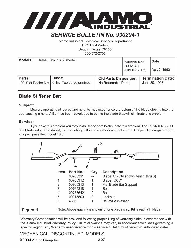
Blade Stiffener Bar:
Subject:Mowers operating at low cutting heights may experience a problem of the blade dipping into the
sod causing a hole. A Bar has been developed to bolt to the blade that will eliminate this problem
Service:If you have this problem you may install these bars to eliminate this problem. The kit P/N 00765311
is a Blade with bar installed, the mounting bolts and washers are included, 3 kits per deck required or 9kits per grass flex model 16.5'
Models: Grass Flex- 16.5' model Date:
Apr. 2, 1993
Bulletin No: 930204-1(Old # 93-002)
Parts:100 % at Dealer Net
Labor:.0 hr. Toe be determined
Termination Date:Jun. 30, 1993
Old Parts Disposition:No Returnable Parts
Warranty Compensation will be provided following proper filing of warranty claim in accordance withthe Alamo Industrial Warranty Policy. Claim allowance may vary in accordance with laws governing aspecific region. Any Warranty associated with this service bulletin must be within authorized dates.
Item Part No. Qty Description00765311 -- Blade Kit (Qty shown item 1 thru 6)
1. 00765312 1 Blade. CCW2. 00765313 1 Flat Blade Bar Support3. 00765318 1 Bolt4. 00753642 2 Bolt5. 00015800 2 Locknut6. 4816 1 Belleville Washer
Note: Above quanity is shown for one blade only. Kit is each (1) bladeFigure 1
1
2
3
4
5
6

© 2004 Alamo Group Inc. 2-28
MECHANICAL DISCONTINUED MODELS
SERVICE BULLETIN No. 930204-2Alamo Industrial Technical Services Department
1502 East WalnutSeguin, Texas 78155
830-372-2708
Front Roller Bearing Upgrade :
Subject:There are mowing operations and mowing conditions where a stronger front roller bearing is
needed. There is a Roller which has been designed to be stronger than the stock roller, The Stronger rolleris kit P/N 00765314, this kit has one roller and hardware, it will be required to order kits one for each deck(3 decks per grass flex). These rioller are optional and not required.
Service:Replace standard roller with updated roller and bracket assembly as shown.
Models: Grass Flex- 16.5', 15.5', 14.5' & 13.5' models Date:
Apr. 2, 1993
Bulletin No: 930204-2(Old # 93-005)
Parts:100 % at Dealer Net
Labor:.0 hr. Toe be determined
Termination Date:Jun. 30, 1993
Old Parts Disposition:No Returnable Parts
Warranty Compensation will be provided following proper filing of warranty claim in accordance withthe Alamo Industrial Warranty Policy. Claim allowance may vary in accordance with laws governing aspecific region. Any Warranty associated with this service bulletin must be within authorized dates.
1
2
3
4
5
6
78
9 Item Part No. Qty Description
1. 00765316 1 Plate, Brkt. RH2. 00765317 1 Plate, Brkt. LH3. 00765315 1 Roller Assembly4. 00764933 1 Axle Weldment5. 02822500 2 Flatwasher6. 00753642 4 Bolt7. 4528 4 Locknut8. 00750959 1 Bolt9. 00001800 1 LocknutFigure 1

© 2004 Alamo Group Inc. 2-29MECHANICAL DISCONTINUED MODELS
SERVICE BULLETIN No. 930207Alamo Industrial Technical Services Department
1502 East WalnutSeguin, Texas 78155
830-372-2708
Rear Lift Chains & Wing Transport Bars:
Subject:Rear lift Chains on center rear deck and wing transport bars, Inspect parts to make sure correct
parts are installed from factory.
Service Required:Check number of links in rear deck lift chains. Make certain there are only 5 links used, any excess
links will have to be cut off. Shackles will have to be connected to first link and fifth link only See Figure 1and parts manual for detail description of parts.
Check wing transport bar to make certain that there is a slotted hole in one end, if not, replace thetransport bar with P/N 00763795, or cut slotted hole as shown in figure 1.
Models: Grass Flex, S/N 10001 to 10065 Date:
Jul. 2, 1993
Bulletin No: 932903(Old # 93-007)
Parts:100 % at Dealer Net
Labor:.0 hr. To be determined
Termination Date:Sep. 30, 1993
Old Parts Disposition:No Returnable Parts
Warranty Compensation will be provided following proper filing of warranty claim in accordance withthe Alamo Industrial Warranty Policy. Claim allowance may vary in accordance with laws governing aspecific region. Any Warranty associated with this service bulletin must be within authorized dates.
Wing Transport Bar1 Round Hole1 Slotted Hole
Lift Chain. 5 Links
Figure 1

© 2004 Alamo Group Inc. 2-30
MECHANICAL DISCONTINUED MODELS
SERVICE BULLETIN No. 942501Alamo Industrial Technical Services Department
1502 East WalnutSeguin, Texas 78155
830-372-2708
Spindle Upgrade (GF):
Subject:Replace parts on all mowing heads at the same time. Kits must be ordered by size of mower head,
72" head is kit P/N 00768960 and the 60" kit is P/N 00768959. Each kit will consist of enough parts to changeone deck (3 decks per grass flex). This will only pertain to units unsold and in dealer inventory.Service Required:
Remove blades, spindles, belt sheaves and associated hardware from mowing decks. Retain allparts to be returned to factory for credit. Install new parts supplied in the kits. Notice: inbound and outboundFreight for parts will be allowed as warranty.
Check bearing pre-load by applying force to blade. If movement is noticed, remove sheave andtighten adjusting nut, Do not overtighten as this will cause heat build up in spindle and damage bearings.
Models: Grass Flex, GF16.5, 15.5', 14.5' & 13.5'Units in dealer inventory only need to be changed.S/N 10124 and under only
Date:
Jan. 25, 1994
Bulletin No: 942501(Old # 940003)
Parts:100 % at Dealer Net
Labor:6.0 hr. At DealerRegistered Labor Rate
Termination Date:Mar. 30, 1994
Old Parts Disposition:Hold Parts For Return
Warranty Compensation will be provided following proper filing of warranty claim in accordance withthe Alamo Industrial Warranty Policy. Claim allowance may vary in accordance with laws governing aspecific region. Any Warranty associated with this service bulletin must be within authorized dates.
Figure 1
Item Part No. Qty Description
1. 00766532 3 Spindle Housing Asy.2. 00766448 3 Sheave, Double Groove3. 00766480 3 Blade Bolt4. 00766077 3 Washer5. 00766572 3 Blade, 60" Mower Only
00765445 3 Blade, 72" Mower Only6. 00766548 3 Top Lock Jam Nut7. 15B1400 3 Washer8. 02959013 3 Square Key
Quantity Shown for one deck only
1
2
34
5
6,7
8

© 2004 Alamo Group Inc. 2-31MECHANICAL DISCONTINUED MODELS
SERVICE BULLETIN No. 951704Alamo Industrial Technical Services Department
1502 East WalnutSeguin, Texas 78155
830-372-2708
Gauge Wheel Relocation :
Subject:In some instances the inside rear gauge wheel tire on the wings will interfere with the large dolly
tire
Service Required:Drill new holes in deck to enable the gauge wheel axle beam to be moved on deck three inches.
This move will allow the tire clearence needed. Used drawing in figure 1 to relocate Axle beam on deckusing the existing hardware.
Models: Grass Flex, GF15.5 Date:
Apr. 17, 1995
Bulletin No: 951704(Old # 950005)
Parts:100 % at Dealer Net
Labor:0.5 hr. At DealerRegistered Labor Rate
Termination Date:Jun 30, 1995
Old Parts Disposition:No Returnable Parts
Warranty Compensation will be provided following proper filing of warranty claim in accordance withthe Alamo Industrial Warranty Policy. Claim allowance may vary in accordance with laws governing aspecific region. Any Warranty associated with this service bulletin must be within authorized dates.
LargeDollyTire
Interference Zone
Gauge Wheel Tire
This hole should already be in deck
3"
Drill this hole 3"toward centerof deck, holedia. 13/32"
Existing holes
From this current hole at the equaldistance from the back of the deck
Figure 1

© 2004 Alamo Group Inc. 2-32
MECHANICAL DISCONTINUED MODELS
SERVICE BULLETIN No. 971612Alamo Industrial Technical Services Department
1502 East WalnutSeguin, Texas 78155
830-372-2708
Clutch Coil Spring Kits :
Subject:During September of 1996, utilization of a "springless" design 2 and 4 disk slip clutch (figure 1)
was implemented for use in several mower models. This design was used to replace the original externalcoil spring design (Figure 2), and provided equal levels of durability and safety along with a cleanerappearance. However, the difficulty involved in adjusting this clutch, along with its lack of acceptance bycustomers, has necessitated the discontinuation of the new clutch, and a return to the old design.
Service Required:Convert the new internal spring (Springless) design clutch to the old coils spring design using
the conversion kits listed. 2 disk clutch use kit P/N 00773222 & 4 disk clutch use kit P/N 00773224.The Spring Kits will include pressure plate, Bolts, Nuts and Springs (Kit will not included clutch lining)1. Remove the clutch from the gearbox. Disassemble the clutch assembly and remove thepressure plate along with the nuts and bolts.2. Reassemble the clutch using the diagram and parts breakdown located in the parts section ofthe Operators manual. Install all the parts, pressure plate, springs, bolts and nuts.3. Adjust the clutch in accordance with the instructions provided in the Operators manual.
Models: All AG Mechanical mowers using either the 2 or 4 diskinternal spring design (Springless) slip clutchClutch P/N 00756075A (4 disk) or 00754320A (2 disk)
Date:
Dec. 16, 1997
Bulletin No: 971612(Old # 970011A)
Parts:100 % at Dealer Net
Labor:1.0 hr. At Dealer RegisteredLabor Rate
Termination Date:Feb 28, 1998
Old Parts Disposition:Retain Parts for return
Warranty Compensation will be provided following proper filing of warranty claim in accordance withthe Alamo Industrial Warranty Policy. Claim allowance may vary in accordance with laws governing aspecific region. Any Warranty associated with this service bulletin must be within authorized dates.
Figure 1 Figure 2
Internal Spring(Springless)Clutch
External Spring(Coil Spring)Clutch
© 2004 Alamo Group Inc. 2-33MECHANICAL DISCONTINUED MODELS
SERVICE BULLETIN No. 981704Alamo Industrial Technical Services Department
1502 East WalnutSeguin, Texas 78155
830-372-2708
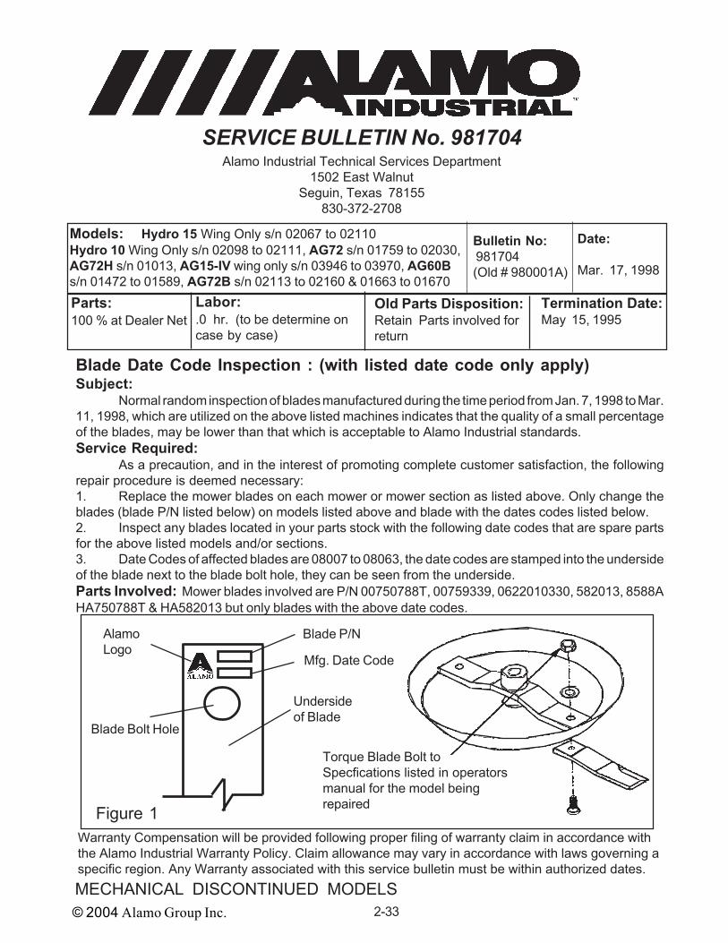
Blade Date Code Inspection : (with listed date code only apply)Subject:
Normal random inspection of blades manufactured during the time period from Jan. 7, 1998 to Mar.11, 1998, which are utilized on the above listed machines indicates that the quality of a small percentageof the blades, may be lower than that which is acceptable to Alamo Industrial standards.Service Required:
As a precaution, and in the interest of promoting complete customer satisfaction, the followingrepair procedure is deemed necessary:1. Replace the mower blades on each mower or mower section as listed above. Only change theblades (blade P/N listed below) on models listed above and blade with the dates codes listed below.2. Inspect any blades located in your parts stock with the following date codes that are spare partsfor the above listed models and/or sections.3. Date Codes of affected blades are 08007 to 08063, the date codes are stamped into the undersideof the blade next to the blade bolt hole, they can be seen from the underside.Parts Involved: Mower blades involved are P/N 00750788T, 00759339, 0622010330, 582013, 8588AHA750788T & HA582013 but only blades with the above date codes.
Models: Hydro 15 Wing Only s/n 02067 to 02110Hydro 10 Wing Only s/n 02098 to 02111, AG72 s/n 01759 to 02030,AG72H s/n 01013, AG15-IV wing only s/n 03946 to 03970, AG60Bs/n 01472 to 01589, AG72B s/n 02113 to 02160 & 01663 to 01670
Date:
Mar. 17, 1998
Bulletin No: 981704(Old # 980001A)
Parts:100 % at Dealer Net
Labor:.0 hr. (to be determine oncase by case)
Termination Date:May 15, 1995
Old Parts Disposition:Retain Parts involved forreturn
Warranty Compensation will be provided following proper filing of warranty claim in accordance withthe Alamo Industrial Warranty Policy. Claim allowance may vary in accordance with laws governing aspecific region. Any Warranty associated with this service bulletin must be within authorized dates.
Figure 1
Mfg. Date Code
Undersideof Blade
Blade Bolt Hole
Blade P/NAlamoLogo
Torque Blade Bolt toSpecfications listed in operatorsmanual for the model beingrepaired

© 2004 Alamo Group Inc. 2-34
MECHANICAL DISCONTINUED MODELS
SERVICE BULLETIN No. 002112Alamo Industrial Technical Services Department
1502 East WalnutSeguin, Texas 78155
830-372-2708
Blade Replacement Notice, Rotary Mowers:Subject:
During random inspection of rotary mower blades, we determined that a small quantity of bladesmay be of a quality lower than that which is acceptable to Alamo Industrial. These blades can beidentified by the Alamo Industrial Logo, Part Number and Date code that is stamped on the blade nextto the blade bolt hole (See Figure 1). Refer to the Blade Numbers listed in this bulletin and theircorresponding date codes to identify the blades to be replaced.Service Required:
To prevent possible blade failures, the following repair procedure is deemed necessary.Immediately inspect all Alamo Industrial Rotary Mowers to determine if they are fitted with bladesidentified in this bulletin. Replace all blades that have matching part numbers and date codes listed onthe following pages. Inspect all of your Parts Inventory of blades to determine if any of these blades onhand match the part numbers and date code. Only blade with matching part number AND date codeswill apply to this bulletin. Blade can be check without removing them as the part number and date codesare on the underside of the blade.Parts Required:
Rotary Mower Blades on mowers and / or in parts inventory should be replaced if numbers anddate codes match those listed.
Models: Any Rotary Mower using any of the blade Part Numberswith the indicated date codes listed in this bulletin.
Date:
Dec. 21, 2000
Bulletin No: 002112(Old # 122100A)
Parts:100 % at Dealer Net
Labor:Refer to Alamo Flat ratemanual for labor time
Termination Date:Apr. 30, 2001
Old Parts Disposition:Retain Removed Parts forRecall
Continued Next Page
Figure 1
Mfg. Date Code
Undersideof Blade
Blade Bolt Hole
Blade P/NAlamoLogo
Torque Blade Bolt toSpecfications listed in operatorsmanual for the model beingrepaired

© 2004 Alamo Group Inc. 2-35MECHANICAL DISCONTINUED MODELS
Warranty Compensation will be provided following proper filing of warranty claim in accordance withthe Alamo Industrial Warranty Policy. Claim allowance may vary in accordance with laws governing aspecific region. Any Warranty associated with this service bulletin must be within authorized dates.
Service Bulletin 002112 Continued from previous Page
SERVICE BULLETINNo. 002112
NOTICE:The following list of Blades and date codes are the only blades that this bulletin applies to. The
part number with the corresponding date code must be stamped on the same blade. Do Not changea blade based on part number or date code alone.
Blade Part No. Date Code
00127028....................................................... 0158 or 0159 or H1094
00750787T..................................................... 0080 or 0081
00750788T..................................................... 0073 or 0075
00752974....................................................... 0295
00753254....................................................... 0110 or A09619
00753841....................................................... 0166 or 0167 or 0306
00753842....................................................... 0165 or 0166
00762435....................................................... 0167
00770975....................................................... 8306 or 9321
02726900....................................................... 0089 or 0129 or 0131 or 0130 (*)
02886200....................................................... 0215
02962635....................................................... 0201
02964824....................................................... 0027
0582010330................................................... 0180 or 0285 or 0287
1255A............................................................. A000550
582013........................................................... A000660
7520............................................................... 0230
8588............................................................... 0010 or 0095 or 0096 or 0138 or 0251
or 7246 or 9134 or 9258
8589............................................................... 0146 or 0153 or 0158 or 0244 or 0251
8590............................................................... 0143 or 0144 or 0234
(*) Heat Code

© 2004 Alamo Group Inc. 2-36
MECHANICAL DISCONTINUED MODELS
SERVICE BULLETIN No. 011704Alamo Industrial Technical Services Department
1502 East WalnutSeguin, Texas 78155
830-372-2708
Blade Replacement Notice, Rotary Mowers: - SECOND NOTICE -Subject:
During random inspection of rotary mower blades, we determined that a small quantity of bladesmay be of a quality lower than that which is acceptable to Alamo Industrial. These blades can beidentified by the Alamo Industrial Logo, Part Number and Date code that is stamped on the blade nextto the blade bolt hole (See Figure 1). Refer to the Blade Numbers listed in this bulletin and theircorresponding date codes to identify the blades to be replaced.Service Required:
To prevent possible blade failures, the following repair procedure is deemed necessary.Immediately inspect all Alamo Industrial Rotary Mowers to determine if they are fitted with bladesidentified in this bulletin. Replace all blades that have matching part numbers and date codes listed onthe following pages. Inspect all of your Parts Inventory of blades to determine if any of these blades onhand match the part numbers and date code. Only blade with matching part number AND date codeswill apply to this bulletin. Blade can be check without removing them as the part number and date codesare on the underside of the blade.Parts Required:
Rotary Mower Blades on mowers and / or in parts inventory should be replaced if numbers anddate codes match those listed.
Models: Any Rotary Mower using any of the blade Part Numberswith the indicated date codes listed in this bulletin.
- SECOND NOTICE -
Date:
Apr. 17, 2001
Bulletin No: 011704(Old # 041701B)
Parts:100 % at Dealer Net
Labor:Refer to Alamo Flat ratemanual for labor time
Termination Date:May. 30, 2001
Old Parts Disposition:Retain Removed Parts forRecall
Continued Next Page
Figure 1
Mfg. Date Code
Undersideof Blade
Blade Bolt Hole
Blade P/NAlamoLogo
Torque Blade Bolt toSpecfications listed in operatorsmanual for the model beingrepaired

© 2004 Alamo Group Inc. 2-37MECHANICAL DISCONTINUED MODELS
Warranty Compensation will be provided following proper filing of warranty claim in accordance withthe Alamo Industrial Warranty Policy. Claim allowance may vary in accordance with laws governing aspecific region. Any Warranty associated with this service bulletin must be within authorized dates.
Service Bulletin 011704 Continued from previous Page
SERVICE BULLETINNo. 011704
NOTICE:The following list of Blades and date codes are the only blades that this bulletin applies to. The
part number with the corresponding date code must be stamped on the same blade. Do Not changea blade based on part number or date code alone.
Blade Part No. Date Code
00127028....................................................... 0158 or 0159 or H1094
00750787T..................................................... 0080 or 0081
00750788T..................................................... 0073 or 0075
00752974....................................................... 0295
00753254....................................................... 0110 or A09619
00753841....................................................... 0166 or 0167 or 0306
00753842....................................................... 0165 or 0166
00762435....................................................... 0167
00770975....................................................... 8306 or 9321
02726900....................................................... 0089 or 0129 or 0131 or 0130 (*)
02886200....................................................... 0215
02962635....................................................... 0201
02964824....................................................... 0027
0582010330................................................... 0180 or 0285 or 0287
1255A............................................................. A000550
582013........................................................... A000660
7520............................................................... 0230
8588............................................................... 0010 or 0095 or 0096 or 0138 or 0251
or 7246 or 9134 or 9258
8589............................................................... 0146 or 0153 or 0158 or 0244 or 0251
8590............................................................... 0143 or 0144 or 0234
(*) Heat Code

© 2004 Alamo Group Inc. 2-38
MECHANICAL DISCONTINUED MODELS
NOTES


© 2004 Alamo Group Inc.
Discontinued Mechanical Models Technical Information and
Service Bulletin Manual
Manual P/N 02980507(01/04)