discovering high-level bpmn process models from...
TRANSCRIPT

Noname manuscript No.(will be inserted by the editor)
Discovering High-level BPMN Process Models from EventData
A. A. Kalenkova · A. Burattin · M. de Leoni ·W. M. P. van der Aalst · A. Sperduti
Received: / Accepted: date
Abstract Process mining is a well established research discipline comprising approachesfor process analysis based on the history of process executions. One of the main directionsin the process mining field is process discovery. Process discovery aims to develop methodsfor constructing process models from the event logs. The ultimate goal of process discoveryis to obtain readable process models, which represent process behavior in the best possibleway. Process discovery techniques rarely use higher-level process modeling notations likeBPMN and tend to focus on the control-flow perspective. However, end-users are morefamiliar with notations like BPMN and are interested in the data and resource perspectives.This paper gives an overview of existing process discovery techniques and presents a BPMNmeta-model, which describes models that can be obtained from the event logs using existingdiscovery techniques. Besides that the paper presents an integrated discovery approach forthe construction of high-level BPMN models that comply with the BPMN meta-model. Theproposed integrated approach was applied to real-life event logs and it was shown that itallows for obtaining readable process models, which reflect the process behavior.
Keywords process mining, process discovery, BPMN (Business Process Model andNotation), process modeling perspectives
This work was supported by the Basic Research Program at the National Research University Higher Schoolof Economics, funded by RFBR and Moscow city Government according to the Research project No 15-37-70008 “mol_a_mos” and RFBR (Project No 15-37-21103) and was supported by the Eureka-EurostarsPROMPT project (E!6696).
A. A. KalenkovaNational Research University Higher School of Economics, Moscow, RussiaE-mail: [email protected]
A. BurattinUniversity of Innsbruck, Innsbruck, AustriaE-mail: [email protected]
M. de Leoni ·W. M. P. van der AalstEindhoven University of Technology, Eindhoven, NetherlandsE-mail: [email protected],[email protected]
A. SperdutiThe University of Padua , Padua, ItalyE-mail: [email protected]

2 A. A. Kalenkova et al.
1 Introduction
Information systems in different domains, such as healthcare, tourism, banking, governmentand others, record operational behavior in the form of event logs. The process mining disci-pline [1] offers dozens of techniques to discover, analyze, and visualize processes runningin information systems basing on the event logs. The representational bias (the languagefor processes representation) plays an important role in the process discovery. In this workwe take BPMN language [24] as a representational bias and as a starting point for processdiscovery. BPMN is a common process modeling language widely used by analysts and pro-grammers in various domains. This work aims to bridge the gap between existing processmining techniques and BPMN – a commonly used industrial process modeling standard.Although there exist techniques [9, 10, 14, 16] for discovering some of the BPMN modelingconstructs, these are often limited to a single perspective, e.g., just the control flow, sub-processes, or just resources. The goal of this work was to formalize and project the BPMNspecification onto the process mining domain and suggest a unified integrated approach al-lowing for the discovery of multiperspective BPMN models. Such an approach gives anability not only to analyze and visualize discovered processes in BPMN-complaint editors,but even automate their executions using one of the BPMN engines.
First, we analyzed the BPMN meta-model [24], extracting the main modeling elements,which can be discovered using process mining techniques. Thus, three main types of BPMNmodels, which inherit core BPMN modeling constructs were identified: BPMN models withdata, hierarchical BPMN models and BPMN models with resources. Formal execution se-mantics for these types of models were defined. After that we analyzed the applicabilityof the existing process discovery techniques to mine these specific models. For hierarchi-cal BPMN models a novel algorithm, which uses a well-defined method for constructingcomposite process models from localized event logs [4], was adopted and justified. It wasproven that each log trace that can be replayed by a composite process model, constructedfrom a localized event log, can be replayed by the target hierarchical BPMN model. Thenan integrated approach for mining integrated BPMN models, which combines different per-spectives, including data, resource, and hierarchical BPMN models, was developed. Theintegrated discovery approach was implemented as plugin for ProM (Process Mining Frame-work) [13]. It was evaluated using real-life event logs taken from government, online salesand banking domains. The underlying approach for discovering composite process modelsfrom localized event logs [4] allows us to apply some of the techniques, such as resourcediscovery and alignment construction, to each of the submodels, thus significantly reducingthe overall discovery time. The behavioral and structural characteristics of the discoveredBPMN models were also evaluated. The structural characteristics of BPMN models discov-ered from real-life event logs were compared with the structural characteristics of BPMNmodels taken from the Signavio model collection, and thus, it was shown that the modelsdiscovered automatically using the integrated approach resemble manually created models,which are common for the analysts.
The remainder of this paper is organized as follows. Section 2 gives an overview ofrelated work. In Section 3 all notions, including event logs, Petri nets, BPMN modelingconstructs are introduced. Besides that Section 3 presents semantics for various types ofBPMN modeling constructs. Section 4 demonstrates the applicability of the existing pro-cess discovery techniques to mine different types of BPMN models. Moreover, Section 4introduces and justifies an approach for the discovery of hierarchical BPMN models, usingtechniques described in [4]. An integrated discovery approach is presented in Section 4 as
Discovering High-level BPMN Process Models from Event Data 3
well. Section 5 describes implementation aspects of the integrated discovery approach. Allexperimental results are presented in Section 6. Section 7 concludes the paper.
2 Related Work
Recently a few techniques for discovering BPMN models from event logs were proposed.In [9, 14] a novel method for mining hierarchical BPMN models with subprocesses is pre-sented. Paper [10] suggests an approach for discovering BPMN models represented by con-trol and resource perspectives.
Our approach is an extension of the previous work limited to flat BPMN models discov-ery [16, 17]. In [16] a conversion algorithm for relating Petri nets and flat BPMN modelsis introduced and justified. This algorithm gives a solid background for applying advanceddiscovery techniques proposed in this paper. In [17] technical aspects of its implementationare presented.
In contrast to the approaches [10], which are limited to just the control and resource per-spectives, and based on a rather specific process discovery algorithm, we present a flexiblediscovering framework based on the BPMN meta-model tailored towards the process min-ing field. Thus, our approach incorporates various discovery techniques in a flexible manner,allowing discovering data flows, subprocesses and other modeling elements.
The subprocess discovery technique presented in this paper is based on a robust ap-proach for discovering composite process models from localized event logs enriched withadditional information on the so-called "location" of events (enabling the discovery of hier-archical models) [4]. The approach [4] gives formal guarantees on replay of the log traces,is flexible and can be potentially used for the discovery of different types of communicationconstructions. In this work we used it for mining subprocesses with multiple arbitrary out-going flows modeled as cancellations, while in [9, 14] only global cancellations, which leadto a termination event of the entire process model are discovered. Moreover, in comparisonwith [9, 14] due to the formal nature of the approaches [4] and [16] the language inclusionproperty of the proposed subprocess discovery technique was verified.
3 Event Logs, Petri Nets, and BPMN Modeling Constructs
This section defines main concepts, including event logs and process modeling formalisms,which will be referred later in this paper.
3.1 Event Logs
Event logs, containing information systems’ behavior, are considered as a starting point forthe process discovery algorithms.
The definition of event logs reflects the definition reported in [4]. Let UA be a set ofpossible activity names, UAttr and UVal be sets of event attributes and their values.
A tuple L = (E,Tr, act, attr) is called an event log, if E is a set of events, Tr ⊆ E? is aset of traces (each trace is a sequence of events), act : E → UA maps events onto activitynames, and attr : E → (UAttr 9 UVal)
1 defines per event the attributes and their values.Consider the fragment of an event log presented in Tab. 1. This event log contains infor-
19 denotes a partial function, which is defined for a subset of domain elements.

4 A. A. Kalenkova et al.
Case ID Activity Name Resource Time (minutes)e1 1 "receive application" "John" -e2 1 "send acknowledgment of receipt" "John" 1e3 2 "receive application" "Mary" -e4 1 "process application" "Kate" 124e5 2 "send acknowledgment of receipt" "Mary" 5e6 2 "forward to competent authority" "Jane" 25
Table 1: An event log of an application processing procedure.
mation about executions of an application processing procedure. The arrival of an applica-tion initiates a process instance. After the application is received an acknowledgment is sentback to the applicant and the application is either processed or forwarded to a competentauthority. Each case (identified by the attribute Case ID) corresponds to the processing of aconcrete application and represents a sequence of events (a trace). The values of Resourceand Time attributes are given for these events. The resource attribute sets an event performer,while Time attribute presents time in minutes needed for the execution of a correspondingoperation. More formally, this event log can be defined as a tuple L = (E,Tr, act, attr),where E = {e1, e2, e3, e4, e5, e6}, Tr = {〈e1, e2, e4〉 , 〈e3, e5, e6〉}, act(e1) = act(e3) ="receive application", act(e2) = act(e5) = "send acknowledgment of receipt", act(e4) ="process application", act(e6) = "forward to competent authority". Event attributes are de-fined in the following way: attr(e1)("Resource") = "John", attr(e2)("Time") = "1", whereUA = { "receive application", "send acknowledgment of receipt", "process application","forward to competent authority" }, UAttr = { "Resource", "Time" }, UVal = { "John","Mary", "Kate", "Jane", 1, 5, 25, 124 }.
Suppose that E′ ⊆ E is a subset of events, then the projection L↑E′ of the log L =(E,Tr, act, attr) on set E′ is defined as follows: L↑E′ = (E↑E′ ,Tr↑E′ , act↑E′ , attr↑E′),where E↑E′ = E∩E′, act↑E′ = act∩ (E′ → UA), attr↑E′ = attr∩ (E′ → (UAttr 9 UVal)),and Tr↑E′ = {t↑E′ |t ∈ Tr}, where t↑E′ is defined inductively: if t = 〈〉, then t↑E′ = 〈〉, ift = 〈e〉 · t′, and e ∈ E′, then t↑E′ = 〈e〉 · t′↑E′ , if e /∈ E′, then t↑E′ = t′↑E′ .
3.2 Petri Nets
Petri nets is the most popular low-level process modeling formalism used in the context ofprocess mining. A Petri net is a tuple PN = (P, T, F,Minit,Mfinal), where P is the set ofplaces, T is the set of transitions, P ∩ T = ∅, and F ⊆ (P × T ) ∪ (T × P ) is the flowrelation, and Minit,Mfinal are initial and final markings respectively. A marking is a functionM ∈ P → N, which maps places to natural numbers. Thus, Minit,Mfinal ∈ P → N. In amarking M place p contains M(p) tokens represented as black dots. In addition, we will usethe following notation: by [p1, p
32] we will denote a marking, in which place p1 contains one
token, place p2 contains three tokens, while other place are empty.For transition t sets of input and output places are defined as: •t = {p ∈ P |(p, t) ∈ F},
and t• = {p ∈ P |(t, p) ∈ F} correspondingly. Places are represented by circles, transitionsby boxes, and the flow relation by directed arcs.
Transition t is enabled in marking M iff ∀p ∈ •t : M(p) ≥ 1, i.e., each input placecontains at least one token. An enabled transition t may fire, i.e., one token is removed fromeach of the input places •t and one token is added to each of output places t•.

Discovering High-level BPMN Process Models from Event Data 5
A labeled Petri net PN = (P, T, F,Minit,Mfinal, l) is defined as a Petri net (P, T, F,Minit,
Mfinal) and a labeling function l ∈ T 9 UA, which maps transitions to a universe of activitynames. If l is not defined for t ∈ T , then t is called invisible and represented as a black box.Function l can be applied to transition sequences using the following inductive definition:l(〈〉) = 〈〉, l(〈t〉 · σ′) equals l(t) · l(σ′), if l(t) is defined, and l(σ′), otherwise.
Let us consider an event log L = (E,Tr, act, attr). We say that trace 〈e1, ..., ek〉 ∈ Ecan be replayed by a labeled Petri net PN = (P, T, F,Minit,Mfinal, l) if there is a sequenceof transition firings σ, leading from the initial marking Minit to the final marking Mfinal, suchthat l(σ) = 〈act(e1), ..., act(ek)〉.2
Now let us extend Petri nets and define Petri nets with data, which were introduced in[22]. A Petri net with data is a tuple DPN = (PN, V, U,R,W,G), where PN is a labeledPetri net, V is a set of variables, U is a domain function, which defines possible valuesfor each variable v. By D = ∪v∈V U(v) we denote a set of all possible variables’ values.Functions R : T → 2V and W : T → 2V define sets of variables read and written by eachtransition respectively. Guard function G : T 9 GV , where GV is a set of guards, associatestransitions with guards. Variables are shown as circles with dashed boarders, transitions,which read or write variables, are connected with them by incoming or outgoing dashedarrows respectively.
A transition is enabled iff a corresponding guard (in case it was defined for that transi-tion) evaluates to true and all the input places contain at least one token. A state of a Petrinet with data is a pair (M,Val), such that M is a marking, and Val is a function which mapsvariables to its values, i.e., Val : V → D ∪ {⊥}. Sign ⊥ denotes that the variable does nothave a value.
An example of a Petri net with data DPN = (PN, V, U,R,W,G), where PN =(P, T, F,Minit,Mfinal, l) is presented in Fig. 1.
pay by
card
choose
payment
type
book
hotel
view hotel
details
p1 p2
p5
p3 p4 p7
p6
t1t2
t3
t4
t6
t7
pay by
e-money
PaymentType=
''e-money''
PaymentType=
''card''
t5
PaymentType=
''none''
Payment
Type
Fig. 1: An example of a Petri net with data.
This Petri net describes a booking process, where the user first books a hotel,chooses the payment type, pays for the reservation (using one of the payment types)or skips the payment, and views the hotel details (before, after, or during the pay-
2Note that invisible steps in the process model do not need to be observed in the event log.
6 A. A. Kalenkova et al.
ment). Formally, P = {p1, p2, p3, p4, p5, p6, p7}, T = {t1, t2, t3, t4, t5, t6, t7}, F ={(p1, t1), (t1, p2), (t1, p5), (p2, t2), (t2, p3), (p3, t3), (p3, t4), (p3, t5), (t3, p4), (t4, p4), (t5,p4), (p4, t7), (p5, t6), (t6, p6), (p6, t7), (t7, p7)}, l(t1) = "book hotel", l(t2) ="choosepayment type", l(t3) ="pay by e-money", l(t4) ="pay by card", l(t6) ="view hotel details",for transitions t5 and t7 the value of l is not defined. Place p1 contains one token in theinitial marking, formally Minit = [p1], the final marking can be set as Mfinal = [p7]. The setof variables V is represented by a variable PaymentType, i.e., V = {PaymentType}, theset of its possible values is defined as U(PaymentType) = {"e-money","card","none"}.Transition t2 writes the variable PaymentType, transitions t3, t4, and t5 read it, formally,W (t2) = {PaymentType}, R(t3) = R(t4) = R(t5) = {PaymentType}. More-over, guard conditions for t3, t4, and t5 depend on the value of PaymentType: G(t3),G(t4), and G(t5) are defined as "PaymentType="e-money", "PaymentType="card", and"PaymentType="none" respectively, for other transitions the guard function is not specified.This Petri net can replay 8 traces, represented by distinct sequences of activity names. Forinstance, 〈e1, e2, e3, e4〉, where act(e1) = "book hotel", act(e2) = "choose payment type",act(e3) = "view hotel details", act(e4) = "pay by card", is an example of such a trace.
3.3 BPMN Modeling Constructs
In this subsection we will introduce BPMN modeling constructs defined on the basis ofBPMN 2.0 specification [24]. BPMN offers a wide range of modeling elements, but notall of them are frequently employed [23]. In contrast to the existing formal BPMN se-mantics [11, 18, 27] in this paper we consider all key BPMN constructs, which cover themain workflow perspectives: control, resource, and data. We will restrict ourselves to privateBPMN diagrams, which are used to model internal business processes without interactionwith the environment. Modeling and discovering of interacting processes is out of the scopeof this paper and can be considered as a direction for the future work.
We iteratively introduce and formalize various types of BPMN diagrams. To show theirrelations with the BPMN standard corresponding meta-models extracted from [24] enumer-ating all BPMN diagram elements and their relations used in the context of a particulardiagram type are presented. Native classes of modeling elements and abstract classes areshown in white and gray respectively. Classes of BPMN diagrams added in this work arehighlighted in blue. For each native BPMN class a parent package from [24] is specified.
3.3.1 Core BPMN Models
Core BPMN models are used to formalize flat processes represented by control flow per-spective.
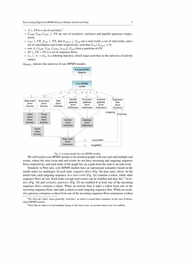
A meta-model, which describes elements of core BPMN models, is presented in Fig. 2.It shows various types of flow nodes, including tasks, gateways, and events. Tasks standfor atomic process steps, gateways are used to model routing constructions, start and endevents denote the beginning and completion of the process respectively. The nodes can beconnected via directed sequence flows independently of their type.
Graphical notations of BPMN elements used within core models are presented in Fig. 3.Let us define core BPMN models formally. A core BPMN model is a tuple BPMNcore =(FN, A,GXOR, GOR, GAND, estart, Eend, Ecancel, SF, λA), where
– FN is a set of flow nodes,
Discovering High-level BPMN Process Models from Event Data 7
– A ⊆ FN is a set of activities,3
– GXOR, GOR, GAND ⊆ FN are sets of exclusive, inclusive and parallel gateways respec-tively,
– estart ∈ FN, Eend ⊆ FN, and Ecancel ⊆ Eend are a start event, a set of end events, and aset of cancellation end events respectively, such that Eend\Ecancel 6= ∅,
– sets A, GXOR, GOR, GAND, {estart}, Eend form a partition of FN,– SF ⊆ FN× FN is a set of sequence flows,– λA ∈ A → UA, is a labeling function, which maps activities to the universe of activity
names.
UBPMNC denotes the universe of core BPMN models.
Private BPMN
diagram
Core BPMN
model
Task
(from
Activities)
1
1..*
Flow node
(from
Common)
Activity
(from
Activities)
Exclusive
gateway
(from
Gateways)
1
1
Gateway
(from
Gateways)
Inclusive
gateway
(from
Gateways)
1
*Parallel
gateway
(from
Gateways)
1
*
Start event
(from
Events)
End event
(from
Events)
11
*
Event
(from
Events)
Throw
event
(from
Events)
Catch
event
(from
Events)
Sequence
flow
(from
Common)
1
*
+outgoing+incoming
* *
+sourceRef1
+targetRef1
*
Fig. 2: A meta-model for core BPMN models.We will restrict core BPMN models to be oriented graphs with one start and multiple end
events, where the start event and end events do not have incoming and outgoing sequenceflows respectively, and each node of the graph lies on a path from the start to an end event.
Similarly to Petri nets, core BPMN models have an operational semantics based on themodel states (or markings). In each state, sequence flows (Fig. 3h) may carry tokens. In theinitial state each outgoing sequence of a start event (Fig. 3a) contains a token, while othersequence flows do not. Each node (except start event) can be enabled and may fire.4 Activ-ities (Fig. 3d) and exclusive gateways (Fig. 3f) are enabled if at least one of the incomingsequence flows contains a token. When an activity fires it takes a token from one of theincoming sequence flows and adds a token to each outgoing sequence flow. While an exclu-sive gateway consumes a token from one of the incoming sequence flows and passes a token
3We will call "tasks" more generally "activities" in order to extend their semantics in the case of hierar-chical BPMN models.
4Note that in order to avoid multiple firings of the start event, we assume that it can’t be enabled.

8 A. A. Kalenkova et al.
to one of the outgoing sequence flows. A parallel gateway (Fig. 3e) is enabled only if eachof the incoming sequence flows contains at least one one token. When an enabled parallelgateway fires, it takes a token from each incoming sequence flow and produces a token toeach outgoing sequence flow. The semantics of inclusive gateways (Fig. 3g) is non-local.
a. b. c.
e. f. g.
h.
d.
Fig. 3: Elements of core BPMN model: a.start event, b. end event, c. cancellation endevent, d. task, e. parallel gateway, f. exclu-sive gateway, g. inclusive gateway, h. se-quence flow.
An inclusive gateway fires if some of the incomingsequence flows contain tokens and it is not possi-ble to reach a marking from the current marking,in which currently empty incoming sequence flowwill contain tokens, without firing this gateway.Inclusive gateway produces tokens for some of theoutgoing sequence flows.
End event (Fig. 3b) consumes all the tokens asthey arrive. Beyond ordinary end events we alsoconsider cancellation end events (Fig. 3c), whichterminate the entire process, consuming all the to-kens from its sequence flows. The BPMN nota-tion contains a wide range of event constructs, thesemantics of which involves cancellation. Thesecould be error, signal, cancel, and other types ofevents. In this paper we combine all of them to-
gether conceptually as one type called cancel events.
3.3.2 BPMN Models with Data
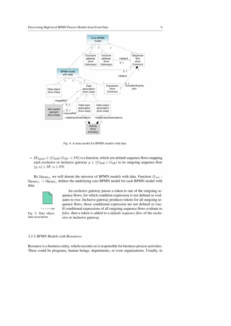
In this subsection we will extend core BPMN modeling constructs by adding the data per-spective. As Fig. 4 shows a BPMN model with data may contain data objects. Activities,which read or write data are connected with corresponding data objects via input or outputdata associations respectively. Fig. 5 shows a graphical representation of a data object anda data association.
Also a BPMN model with data may incorporate conditional expressions. The values ofcondition expression are calculated on the basis of data object values and define conditionsfor passing tokens to the corresponding sequence flows.
Despite the fact that according to the meta-model (Fig. 4) default sequence flows canbe used within core BPMN models, we will add them to BPMN models with data only,since without conditional expressions default sequence flows do not influence the modelexecution.
In contrast to the BPMN specification (Fig. 4), where for any arbitrary sequence flowa corresponding condition expression can be determined, we will assume that conditionexpressions are set only for outgoing sequence flows of exclusive and inclusive gateways.
Formally, BPMN model with data is a tuple BPMNdata =(BPMNcore,DO,DA,Expr, SFdefault), where:
– BPMNcore = (FN, A,GXOR, GOR, GAND, estart, Eend, Ecancel, SF, λA) is a core BPMNmodel,
– DO is a set of data objects,– DA ⊆ (DO×A) ∪ (A×DO) is a set of input and output data associations,– Expr ∈ (SF ∩ ((GXOR ∪ GOR)) × FN) 9 UExpr, where UExpr is a universe of condi-
tional expressions, is a function, which defines conditional expressions for some of theoutgoing sequence flows of exclusive and inclusive gateways,
Discovering High-level BPMN Process Models from Event Data 9
Core BPMN
model
BPMN model
with data
1*
Data
association
(from Data)
Data input
association
(from Data)
Data output
association
(from Data)
Activity
(from
Activities)
+dataInputAssociations
1
+dataOutputAssociations*
1
Item aware
element
(from Data)
1*
Data object
(from Data)
0..1
0..1
*
*
+targetRef
+sourceRef
*
Sequence
flow
(from
Common)
Expression
(from
Common)
1
0..1+conditionExpres
sion
Exclusive
gateway
(from
Gateways)
Inclusive
gateway
(from
Gateways)
*
1
*
0..1
+default
0..1
+default
*
1 1
*1
Fig. 4: A meta-model for BPMN models with data.
– SFdefault ∈ (GXOR∪GOR → FN) is a function, which sets default sequence flows mappingeach exclusive or inclusive gateway g ∈ (GXOR ∪ GOR) to its outgoing sequence flow(g, n) ∈ SF, n ∈ FN.
By UBPMND we will denote the universe of BPMN models with data. Function Dcore :UBPMND → UBPMNC defines the underlying core BPMN model for each BPMN model withdata.
Fig. 5: Data object,data association.
An exclusive gateway passes a token to one of the outgoing se-quence flows, for which condition expression is not defined or eval-uates to true. Inclusive gateway produces tokens for all outgoing se-quence flows, those conditional expression are not defined or true.If conditional expressions of all outgoing sequence flows evaluate tofalse, then a token is added to a default sequence flow of the exclu-sive or inclusive gateway.
3.3.3 BPMN Models with Resources
Resource is a business entity, which executes or is responsible for business process activities.These could be programs, human beings, departments, or even organizations. Usually, in

10 A. A. Kalenkova et al.
private BPMN models resources are represented as lanes.5 An example of a BPMN modelwith lanes is presented in Fig. 6.
Lane2
Lane1
A
B
Fig. 6: An example of a BPMN model with lanes.
A meta-model for BPMN models withresources is shown in Fig. 7. As one maysee from this meta-model, each lane be-longs to a lane set, which in turn can becontained by a lane. Here we will con-sider only one level of granularity. Lanesmay contain flow nodes, such as activities,gateways, events. Note that sequence flowsmay cross lane’s boundaries.
Core BPMN
model
BPMN model
with resources
Lane set
(from
Process)
1
1
Lane
(from
Process)
0..1
+parentLane
0..1
+childLaneSet
+lanes*
1 +laneSet
*
Flow node
(from
Common)
* +lanes
+flowNodesRefs
Fig. 7: A meta-model for BPMN models with re-sources.
Now let us give a formal definitionof BPMN models with resources, whichincorporates a set of lanes and a mappingfunction.
BPMN model with resources is atuple BPMNres = (BPMNcore,Lanes,map), where
– BPMNcore = (FN, A,GXOR, GOR,
GAND, estart, Eend, Ecancel, SF, λA) isa core BPMN model,
– Lanes is a set of lanes representingresources,
– map : FN 9 Lanes is a partial func-tion which maps some of the nodesonto set of lanes.
UBPMNR denotes the universe of BPMN models with resources, function Rcore :UBPMNR → UBPMNC specifies underlying core BPMN models for BPMN models with re-sources.
3.3.4 Hierarchical BPMN Models
A hierarchical BPMN model represents a nested structure of a process by adding subpro-cesses and intermediate cancellation events (Fig. 8).
As it follows from Fig. 8 a subprocess is an activity, which considered as a containerwith inner flow nodes, such as start/end events, tasks, inner subprocesses and gateways.Thus, subprocesses can be represented as core BPMN models.
The behavior of hierarchical BPMN models builds on the behavior of core BPMN mod-els and extends their semantics in execution of non-task activities, i.e., subprocesses.
Each subprocess can be activated if and only if one of the incoming sequence flowscontains a token and there are no tokens inside the subprocess and its child subprocesses.An activated subprocess consumes a token from an incoming sequence flow and produces atoken to each outgoing sequence flow of the inner start event. If the subprocess terminatesnormally (all tokens were consumed by non-cancellation end events), then a token is passedto each regular outgoing sequence flow. In case a cancellation end event terminates the
5Despite the fact that an assignment of lanes is not strictly defined in the BPMN 2.0 specification, mostfrequently they are used to model resources.

Discovering High-level BPMN Process Models from Event Data 11
Core BPMN
model
Hierarchical
BPMN model
Lane set
(from
Process)
Lane
(from
Process)
0..1
+parentLane
0..1
+childLaneSet
+lanes
*
1
+laneSet
Flow
elements
container
(from
Common)
+flowElements
Container
0..1 +laneSets
*
Flow
element
(from
Common)
* +flowElements
Flow node
(from
Common) *
+lanes
+flowNodesRefs
*
Activity
(from
Activities)
Sub
process
(from
Activities)
1
*
Event
(from
Events)
Catch event
(from
Events)
Boundary
event
(from
Events)
+attachedToRef
+boundaryEventRefs
1
*
*
1
Fig. 8: A meta-model for hierarchical BPMN models.
subprocess, then a control is passed to an outgoing sequence flow marked by a correspondingboundary event. We will assume that boundary events are attached to subprocesses only.Namely, we will not consider boundary events attached to tasks.
An example of a subprocess is presented in Fig. 9. The end cancellation event and thecorresponding boundary event are marked with an additional “x” sign.
D
C
B
A
Fig. 9: An example of a BPMN model with subprocesses.
Now let us define hierarchical models formally. A hierarchical BPMN model is a tuple:BPMNh = (BPMNSubProc,BPMN0, H, ref, cancel), where
– BPMNSubProc = {BPMN1, ...,BPMNm}6 is a set of subprocesses, presented by coreBPMN models,
6Let A = A0 ∪A1 ∪ ...∪Am, SF = SF0 ∪ SF1 ∪ ...∪ SFm, and Ecancel = Ecancel0 ∪Ecancel1 ∪ ...∪Ecancelm , where A0, A1,..., Am, SF0,SF1,..., SFm, and Ecancel0 ,Ecancel1 ,..., Ecancelm are sets of activities,sequence flows, and cancellation events of core models BPMN0,BPMN1,...,BPMNm respectively. Note thatthese sets are assumed to be mutually disjoint.

12 A. A. Kalenkova et al.
– BPMN0 is a core BPMN model, which represents the root process model, such thatBPMN0 /∈ BPMNSubProc,
– H : BPMNSubProc×(BPMNSubProc∪{BPMN0}) is a tree relation, which specifies a parentmodel for each model from BPMNSubProc, where BPMN0 acts as a root of this tree,
– ref : A 9 BPMNSubProc, is an injective function, such that ∀i ∈ 0,m∀j ∈ 1,m thefollowing condition: ∃a ∈ Ai : ref(a) = BPMNj iff (BPMNj ,BPMNi) ∈ H , holds,
– cancel : Ecancel → SF is an injective function, which maps cancellation end events ofeach BPMNchild ∈ BPMNSubProc to outgoing sequence flows of activity a marked bycorresponding boundary events, where ref(a) = BPMNchild.
3.3.5 Integrated BPMN Models
Since the aim of this work is to discover integrated BPMN models, consisting of variousperspectives (Fig. 10), we provide the following definition.
An integrated BPMN model is a tuple BPMNi = (BPMNh,FD,FR), where
– BPMNh = (BPMNSubProc,BPMN0, H, ref, cancel) is a hierarchical BPMN model,– FD ∈ (BPMNSubProc ∪ {BPMN0}) 9 UBPMND is a function, which maps core BPMN
models to BPMN models with data, such that if FD(BPMNcore) = BPMNdata, thenDcore(BPMNdata) = BPMNcore, i.e., BPMNdata extends BPMNcore,
– FR ∈ (BPMNSubProc∪{BPMN0}) 9 UBPMNR maps core BPMN models to BPMN mod-els with resources, if FR(BPMNcore) = BPMNres, then Rcore(BPMNres) = BPMNcore,i.e., BPMNres incorporates BPMNcore and extends it with resources.
Core BPMN
model
Hierarchical
BPMN model
BPMN model
with resources
BPMN model
with data
Integrated BPMN
model
Fig. 10: A meta-model for integrated BPMN models.
As it follows from the definition,each core BPMN model, even if it rep-resents a subprocess, can be extended byboth resources and data. Each lane setmay belong to a flow elements container,which is represented by a process or asubprocess (Fig. 8). That means, eachlane set may be contained by a subpro-cess or a process itself. That also holdsfor data, since (according to the BPMNspecification) each subprocess may haveits own variables.
4 A Framework for Discovering Integrated BPMN Models
4.1 Transforming Flat Process Models to BPMN
Flat process models, such as Petri nets, causal nets and process trees can be obtained fromevent logs by using existing process discovery techniques.
In this subsection approaches for the transformation of flat process models to BPMN,used as a basis for the discovering technique presented in this paper, are introduced by ex-amples. Their detailed formal description can be found in [16]. Moreover, these approacheswere implemented as plugins [17] for ProM [13]. ProM is an open-source framework fordeveloping process mining algorithms.
Discovering High-level BPMN Process Models from Event Data 13
4.1.1 Converting labeled Petri nets
register
book
flight
paybook
hotel
rent
car
Fig. 11: A labeled Petri net of a booking process.
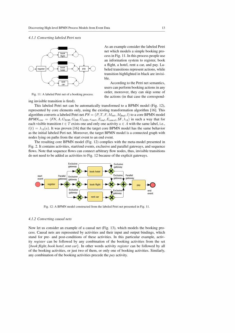
As an example consider the labeled Petrinet which models a simple booking pro-cess in Fig. 11. In this process people usean information system to register, booka flight, a hotel, rent a car, and pay. La-beled transitions represent actions, whiletransition highlighted in black are invisi-ble.
According to the Petri net semantics,users can perform booking actions in anyorder, moreover, they can skip some ofthe actions (in that case the correspond-
ing invisible transition is fired).This labeled Petri net can be automatically transformed to a BPMN model (Fig. 12),
represented by core elements only, using the existing transformation algorithm [16]. Thisalgorithm converts a labeled Petri net PN = (P, T, F,Minit,Mfinal, l) to a core BPMN modelBPMNcore = (FN, A,GXOR, GOR, GAND, estart, Eend, Ecancel, SF, λA) in such a way that foreach visible transition t ∈ T exists one and only one activity a ∈ A with the same label, i.e.,l(t) = λA(a). It was proven [16] that the target core BPMN model has the same behavioras the initial labeled Peri net. Moreover, the target BPMN model is a connected graph withnodes lying on paths from the start event to an end event.
The resulting core BPMN model (Fig. 12) complies with the meta-model presented inFig. 2. It contains activities, start/end events, exclusive and parallel gateways, and sequenceflows. Note that sequence flows can connect arbitrary flow nodes, thus, invisible transitionsdo not need to be added as activities to Fig. 12 because of the explicit gateways.
start
event
Parallel
gateway
Exclusive
gateway
Exclusive
gateway
Exclusive
gateway
book hotel
register book flight
rent car
Exclusive
gateway
Exclusive
gateway
Exclusive
gateway
Parallel
gateway
pay
end
event
Fig. 12: A BPMN model constructed from the labeled Petri net presented in Fig. 11.
4.1.2 Converting causal nets
Now let us consider an example of a causal net (Fig. 13), which models the booking pro-cess. Causal nets are represented by activities and their input and output bindings, whichstand for pre- and post-conditions of these activities. In this particular example, activ-ity register can be followed by any combination of the booking activities from the set{book flight, book hotel, rent car}. In other words activity register can be followed by allof the booking activities, or just two of them, or only one of booking activities. Similarly,any combination of the booking activities precede the pay activity.

14 A. A. Kalenkova et al.
register
book
flight
book
hotelpay
rent
car
Fig. 13: A causal net, which models the booking process.
Each activity of acausal net can be trans-formed to a correspondingBPMN activity.
Exclusive and parallelgateways can be used tomodel bindings. If an ac-tivity has several input oroutput bindings a corre-sponding exclusive gate-way is added. Parallel gate-ways are used model bind-
ings consisting of multiple elements. In contrast to exclusive and parallel gateways inclusivegateways compactly represent bindings within BPMN models.
The causal net presented in Fig. 13 can be transformed to a BPMN model with inclusivegateways (Fig. 14), which naturally model overlapping input and output bindings.
start
event
Inclusive
gateway
book hotel
register book flight
rent car
Inclusivel
gateway
pay
end
event
Fig. 14: A BPMN model with inclusive gateways constructed form the causal net presented in Fig. 13.
4.1.3 Converting process trees
register pay
book
flight
book
hotel
rent
car
Fig. 15: Process of a bookingprocess.
Process trees (Fig. 15) are yet another formalism forprocess modeling. They are often obtained as a resultof applying process discovery algorithms (e.g. Inductiveminer [19] or Genetic miner [6]). They were proposedin [19] and defined as directed trees with root, branchand leaf nodes. Each branch node is considered to bean operator node, leaf nodes stand for atomic activities,while a root node denotes an entire process model.
Process tree is defined inductively:
– a ∈ UA ∪ {τ} is a process tree, representing anatomic activity (τ denotes the silent activity);
– Let M1,...Mn, where n ≥ 1 be process trees, and⊕
be a process tree operator, then⊕
(M1, ...Mn) is aprocess tree.
There can the following types of process tree opera-tors:×denotes the exclusive choice between one of the subtrees,→ is a sequential execu-tion of all subtrees, " means the structured loop, where M1 is a loop body and M2, ...,Mn
are alternative loop back paths (n ≥ 2),∧ denotes parallel execution of all subtrees.

Discovering High-level BPMN Process Models from Event Data 15
An example of a process tree shown in Fig. 15 is inductively converted to a labeled Petrinet presented earlier in Fig. 11. Note that any process tree can be converted to a correspond-ing Petri net, while the opposite is not always true, since there is no guarantee that a givenPetri net is structured.
4.2 Converting Petri Nets with Data to BPMN Models with Data
In this subsection we will introduce an approach for transforming Petri nets with data to dataBPMN models. Note that this approach can be extended to other process models, such ascausal nets and process trees enhanced with data.
Fig. 16: Conversion of data objects, data associations and guards.
Suppose that DPN = (PN, V, U,R,W,G) is an initial Petri net with data. In order totransform this model to a target BPMN model with data BPMNdata = (BPMNcore,DO,DA,Expr, SFdefault), where BPMNcore = (FN, A,GXOR, GOR, GAND, estart, Eend, Ecancel, SF, λA),the following steps are to be performed:
1. labeled Petri net PN = (P, T, F,Minit,Mfinal, l) is converted to a core BPMN modelBPMNcore, using the algorithm described in [16] (without removing activities, whichcorrespond to invisible transitions); by MA : T → A, we denote a function, which mapstransitions to activities;
2. for each variable from V a data object do is created and added to the target BPMNmodel, the mapping of variables to data objects is defined as a function MD : V → DO;
3. for each non-invisible t ∈ T , for each v ∈ R(t), a data input association(MD(v),MA(t)) is added to DA; similarly, for each t ∈ T , for each variable v fromW (t), a data output association (MA(t),MD(v)) is created and added to DA;
4. for each t ∈ T with a guard G(t) an expression for each incoming sequence flow ofactivity MA(t) is set to G(t), if the source node of this sequence flow is an exclusive orinclusive gateway, 7 default condition expressions are chosen in an arbitrary way;
7According to the guard mining algorithm presented in [22] guards are specified for those transitionsonly, preceding places of which form decision points. Thus, these places will be transformed to exclusiveBPMN gateways using existing conversion algorithms.

16 A. A. Kalenkova et al.
5. each activity corresponding to an invisible transition is removed from the target BPMNdiagram along with incoming and outgoing sequence flows in accordance with the sim-plification technique presented in [16]; all outgoing sequence flows of exclusive gate-ways added instead of removed sequence flows inherit condition expressions.
Variables, read and write functions of a data Petri net are trivially transformed to dataobjects, input and output data associations respectively.
To illustrate the conversion of guards let us consider a fragment of a Petri net presentedin Fig. 16 a. and a corresponding fragment of a data BPMN model shown in Fig. 16 b. Thisexample shows that each guard is transformed to condition expressions of correspondingsequence flows.
4.3 Enhancing Core BPMN Models by Adding Resource Perspective
In this subsection an approach for the enhancement of core BPMN models by addingresources will be introduced. The enhancement algorithm takes a core BPMN modelBPMNcore = (FN, A,GXOR, GOR, GAND, estart, Eend, Ecancel, SF, λA), an event log L =(E,Tr, act, attr) as input parameters and enhances BPMNcore with resources by specifyingmap : FN 9 Lanes function, which maps tasks and other elements to lanes, producing aBPMN model BPMNres = (BPMNcore,Lanes,map), where Lanes is a set of resources.
The algorithm is illustrated using an example.8 Let us consider a fragment of the eventlog L = (E,Tr, act, attr), E = {e1, e2, e3, e4, e5, e6}, Tr = {〈e1, e2, e4〉 , 〈e3, e5, e6〉},presented in Tab. 1. For each event a resource performing this event is specified. For ex-ample, attr(e1)("Resource") = attr(e2)("Resource") = "John", attr(e3)("Resource") ="Mary", etc. The initial set of resources, which perform activities is defined as: R =∪e∈E {attr(e)("Resource")}. Thus, R = {"John","Mary","Kate","Jane"}.
Now let us consider a core BPMN model discovered from this log (Fig. 17), using theInductive mining algorithm [20] and the Petri net to BPMN conversion technique presentedin Section 4.1.
receive
application
send
acknowledgment
of receipt
process
application
forward to
competent
authority
t2t1
t3
t4
Fig. 17: A core BPMN model without lanes.
The approach we apply for the further model enhancement [8] assigns each task ofa BPMN model to an aggregate resource (lane), while corresponding events in a logmay be associated with different resources. First, we consider pairs of source and tar-get tasks, which are connected via sequence flow (with possible intermediate gateways),such that for at least one of them t ∈ A exists a corresponding event e ∈ E, for which
8For the detailed description of the approach please refer to [8].
Discovering High-level BPMN Process Models from Event Data 17
act(e) = λA(t) and attr(e)("Resource") is defined.9 In our example these pairs are:(t1, t2), (t2, t3), (t2, t4). Then for each such a pair we define degree of no handover:wtitj =
|Utiti→tj(L) ∩ Utjti→tj
(L)|+|σ=(Uti→tj (L))|
|Utiti→tj(L)|+|Utjti→tj
(L)|, where Utiti→tj
(L) is a multiset over R, such
that r ∈ R belongs to it n number of times, where n = |{ei ∈ E|∃tr ∈ Tr, ∃ej ∈ E,∃α, β ∈E∗ : tr = α·〈ei〉·〈ej〉·β∧act(ei) = λA(ti)∧act(ej) = λA(tj)∧attr(ei)("Resource") = r}|,i.e., it specifies the number of times task ti followed by tj will be executed by resource r.Similarly, Utjti→tj
(L) defines the number of times task tj preceded by ti will be executedby resource r, and σ=(Uti→tj (L)) specifies the number of times tasks ti and tj , where tj ispreceded by ti, are both executed by resource r.
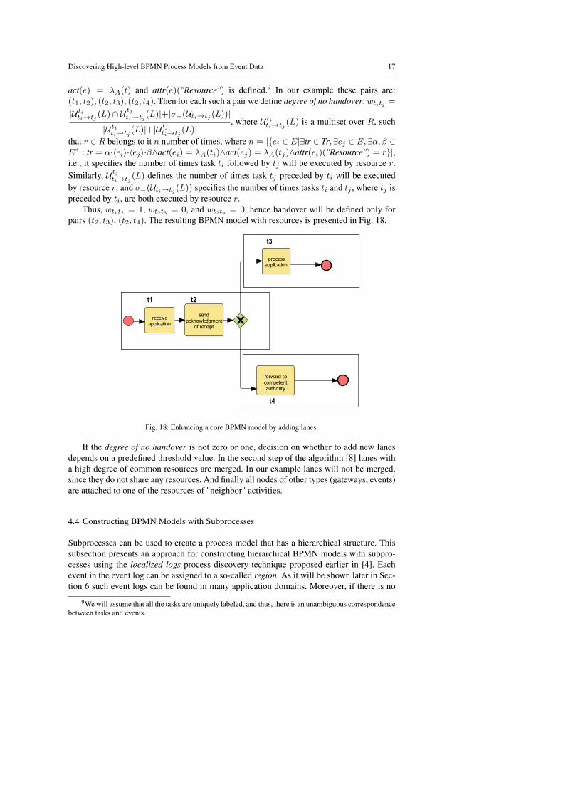
Thus, wt1t2 = 1, wt2t3 = 0, and wt2t4 = 0, hence handover will be defined only forpairs (t2, t3), (t2, t4). The resulting BPMN model with resources is presented in Fig. 18.
receive
application
send
acknowledgment
of receipt
process
application
forward to
competent
authority
t2t1
t3
t4
Fig. 18: Enhancing a core BPMN model by adding lanes.
If the degree of no handover is not zero or one, decision on whether to add new lanesdepends on a predefined threshold value. In the second step of the algorithm [8] lanes witha high degree of common resources are merged. In our example lanes will not be merged,since they do not share any resources. And finally all nodes of other types (gateways, events)are attached to one of the resources of "neighbor" activities.
4.4 Constructing BPMN Models with Subprocesses
Subprocesses can be used to create a process model that has a hierarchical structure. Thissubsection presents an approach for constructing hierarchical BPMN models with subpro-cesses using the localized logs process discovery technique proposed earlier in [4]. Eachevent in the event log can be assigned to a so-called region. As it will be shown later in Sec-tion 6 such event logs can be found in many application domains. Moreover, if there is no
9We will assume that all the tasks are uniquely labeled, and thus, there is an unambiguous correspondencebetween tasks and events.

18 A. A. Kalenkova et al.
register
c1:
r1
r2
c2:
c3:e1
select
flight
select
hotele3
r1
r2
e6 e11select
flighte7
select
hotel
pay
e10register
book flighte8
e9 book hotel
r1
r2
e12 e17select
flighte13
select
hotel
pay
e16
register
book flighte15
e14book hotel
c4:
r1
r2
e18
select
flight
e19select
hotel
register
e20
сancel
hotel
e2
e4r3сancel
e5
r3
cancel
flight e22e21 cancel
Fig. 19: Localized event log of a booking process. Regions r1, r2, and r3 correspond to booking flight,booking hotel, and cancellation procedures respectively.
information on events’ localization, then in most of the cases an event log can be enrichedwith additional data on a basis of expert knowledge.
Now let us give a definition of a localized event log [4]. A localized event log is atriplet LL = (L,R, loc), where L = (E,Tr, act, attr) is an event log, R is a set of regions(or localizations), and loc : E → PNE(R).10 We will consider only stable localized eventlogs. A localized event log LL = (L,R, loc) with L = (E,Tr, act, attr) is called stable iff∀e1, e2 ∈ E, such that act(e1) = act(e2), holds loc(e1) = loc(e2).
An example of a localized event log is presented in Fig. 19. This localized event logcontains four traces and three regions. Events with names "select flight", "book flight" and"select hotel", "book hotel" belong to regions r1 and r2 corresponding to the booking flightand booking hotel procedures respectively. Events named "register", "pay" are attached toboth regions r1 and r2, since these events correspond to both booking procedures. Eventslabeled by "cancel flight" and "cancel hotel" belong to a specific booking region (r1 or r2respectively) and a cancellation region r3, while event with the name "cancel" belongs tothe cancellation region only.
The localized logs discovery approach performs a construction of a target labeledPetri net from a localized event log LL = (L,R, loc), R = {r1, ..., rk}, where L =(E,Tr, act, attr), in three steps:
1. For each region ri ∈ R a labeled Petri net PNi = (Pi, Ti, Fi, li,Miniti ,Mfinali) is dis-covered from a projection of the log L↑Ei
= (E↑Ei,Tr↑Ei
, act↑Ei, attr↑Ei
) on a set ofevents Ei = {e ∈ E|loc(e) ∈ ri}, using one of the existing process discovery tech-niques in such a way that ∀t1, t2 ∈ Tr if li(t1) = li(t2), then t1 = t2, i.e., all transitionsare uniquely labeled11;
2. A resulting labeled Petri net PNU = (P, T, F, l,Minit,Mfinal) is defined as a union of alldiscovered labeled Petri nets PN1, ...,PNk, where transitions with the same labels aremerged;
10PNE(X) defines a set of non-empty subsets of X .11Note that most of the discovery methods allow for constructing such models

Discovering High-level BPMN Process Models from Event Data 19
3. All structurally redundant hanging places and redundant arcs leading to hanging placesare removed.
For the description of the localized logs discovery algorithm please refer to [4].A labeled Petri net constructed from the localized event log (Fig. 19) on the basis of the
Inductive mining approach [20] is shown in Fig. 20. All transitions are highlighted in thecolors of regions they belong to (if a transition belongs to several regions it is highlighted inseveral colors).
register cancel
select
flight
select
hotel
book
flight
pay
book
hotel
cancel
flight
cancel
hotelp1
p2
p3
p4
p5
p6
p7
p8
p9
p10
Fig. 20: A labeled Petri net constructed from the localized event log presented in Fig. 19.
After the labeled Petri net is constructed, it is transformed into a core BPMN model us-ing algorithms presented in [16]. Then the core BPMN is converted to a hierarchical BPMNmodel. For that aim groups af activities corresponding to the same region are identified, andfor each such a group dominating and postdominating activities are found (for the formaldefinitions and an algorithm for finding these activities please refer to [21]). Having domi-nating and postdominating activities it is verified whether these activities can serve as starand end subprocess’s points (it is checked that the subprocess either contains all the activ-ities solely belonging to a region or do not contain any of them, i.e., subprocesses do notintersect and can be only nested into each other). Also it is verified that the subprocess hasonly one start activity and if there are multiple end activities it is additionally checked that allof them except one correspond to the events marked with a special cancellation attribute. Inour example we will assume that the events named "cancel" are marked with a cancellationattribute.
The result of applying conversions and subprocesses identification techniques to thePetri net (Fig 20) is shown in Fig. 21. This hierarchical BPMN model contains one subpro-
register
select flight
select hotel
book flight
cancel flight
cancel hotel
book hotel
pay
cancel
Fig. 21: A hierarchical BPMN model constructed from the labeled Petri net presented in Fig. 20.

20 A. A. Kalenkova et al.
cess, which incorporates all the activities solely belonging to r1 and r2 regions, while the"cancel" activity, solely belonging to the region r3, is outside of its boundaries. The subpro-cess has one start point represented by the "register" activity and two end points representedby the "pay" and "cancel" activities. Since the corresponding events of the "cancel" activityare marked with a cancellation attribute the subprocess is connected with the "cancel" ac-tivity via an intermediate cancellation event attached to its boundary. Activation of the endcancellation event leads to the termination of the subprocess (all the tokens are removed)and yields a token to the outgoing sequence flow marked with the intermediate cancellationevent. If the subprocess terminates normally (all the tokens are consumed by the normal endevent), a token is passed to the regular outgoing sequence flow, activating the "pay" activity.
In contrast to the initial Petri net (Fig. 20), where the traces with cancellations can’t bereplayed (assuming that [p9] is the final state), this hierarchical BPMN model accepts allthe log traces (all the tokens are consumed by the end events). In case one of the bookingprocedures completes successfully, while the other is canceled, the entire BPMN subprocesswill be canceled as well. Moreover, in the hierarchical BPMN model no booking can beperformed after the cancellation, while in the labeled Petri net a booking transition canfire after the other booking procedure was canceled. Thus, the hierarchical BPMN model(Fig. 21) describes the booking process accurately than the corresponding Petri net (Fig. 20).
To show the importance of the regions selection we will consider an event log of thesame booking process with differently chosen regions (Fig. 22). Note that this event log
registerc1:
r1
r2
c2:
c3:
e1 e4
select
flight e2
select
hotel
cancel
e3
r1
r2
e5 e10
select
flighte6
select
hotel
pay
e9
register
book flighte7
e8 book hotel
r1
r2
e11 e16
select
flighte12
select
hotel
pay
e15
register
book flighte14
e13 book hotel
c4:
r1
r2
e17
select
flight
e18select
hotel
e20register
e19
cancel
Fig. 22: Localized event log of a booking process. Regions r1 and r2 correspond to booking flight andbooking hotel procedures respectively.
in contrast to the previous one (Fig. 19) does not contain specific cancellation events, andcancellations are represented by an aggregate cancellation event only. Also note that bothlocalized event logs can be easily constructed one from another during the preprocessing. APetri net discovered from this event log using the localized logs approach [4] on the basis ofthe Inductive miner technique [20] is presented in Fig. 23.
This labeled Petri net can replay any trace from the event log (Fig. 22), assuming that[p1] and [p8] are the initial and the final markings of this Petri net respectively. In [4] it wasproven that: if for each region ri ∈ R trace t↑Ei
can be replayed in PNi, then trace t can bereplayed by the entire model PNU . That is holds for the labeled Petri net (Fig. 23), since foreach region ri ∈ R every trace t↑Ei
can be replayed on a corresponding labeled Petri netPNi.

Discovering High-level BPMN Process Models from Event Data 21
register cancel
select
flight
select
hotel
book
flight
pay
book
hotel
p1
p2
p3
p4
p5
p6
p7
p8
Fig. 23: A labeled Petri net constructed from the localized event log presented in Fig. 22.
A hierarchical BPMN model constructed from the labeled Petri (Fig. 23) is shown inFig. 24. Again we assume that events named "cancel" are marked with a cancellation at-tribute. This BPMN model contains two booking subprocesses with unique start and twofinal activities, one of which corresponds to the events marked with a cancellation attribute.The BPMN model accepts all the traces of the localized event log (all tokens are consumedby the end event). At the same time in contrast to the initial labeled Petri net (Fig. 23) thismodel may reach a so-called dead state, in which no node is enabled, while some sequenceflows contain tokens. This can happen if one of the subprocesses is canceled, while the otherfinished its execution in a regular way. Hence taking this localized event log (Fig. 22) as astarting point the labeled Petri net (Fig. 23) is more preferable as a model for the bookingprocess description than the corresponding hierarchical BPMN model (Fig. 24).
register
select
flight
book flight
pay
cancel
\
select
hotel
book hotel
Fig. 24: A hierarchical BPMN model constructed from the labeled Petri net presented in Fig. 23.
Thus, considering these two examples of localized event logs and corresponding pro-cess models, one may conclude that characteristics of synthesized labeled Petri nets andhierarchical BPMN models dramatically depend on localization of events.
4.5 Integrated Discovery Approach
This subsection presents an integrated discovery approach for constructing hierarchical mul-tiperspective BPMN models. This approach incorporates all methods introduced above.

22 A. A. Kalenkova et al.
The entire schema of the approach is presented in Fig. 25. First, a localizedevent log LL is filtered and logs L1, ..., Lk corresponding to regions are extracted.
Localized
event log LL
Filtering
Discovering Petri nets
Event log L1 Event log Lk
…
Labeled Petri
net PN1
... ...Labeled Petri
net PNk
Replaying event logs
…
Labeled Petri net PN1
Replay result R1
... ...
Merging Petri nets
and replay results
Petri net with
data DPN
BPMN model with data
BPMNdata
Integrated BPMN
model (with data)
BPMN'i
Core BPMN
model BPMN1
Core BPMN
model BPMNm
Integrated BPMN
model (with data and
resources) BPMNi
Labeled Petri net PNk
Replay result Rk
Labeled Petri
net PNReplay result R
Discovering Petri net
with data
Convert to BPMN
Construct subprocesses
Discover roles
Fig. 25: The integrated discovery approach presentedin this paper
After that labeled Petri netsPN1, ...,PNk are discovered fromthese event logs using one of the existingdiscovery techniques.
Then each event log Li is replayedon a corresponding labeled Petri netPNi and an alignment Ri (a sequenceof replay steps, including synchronouslog and model moves, log only andmodel only moves) is constructed. Theselabeled Petri nets and alignments aremerged to a unified Petri net PN anda corresponding alignment R using thetechniques presented in [4] and [26] cor-respondingly.
Next a method for enriching Petrinets with data recorded in the event logsusing a corresponding alignment [22] isapplied, and as a result a Petri net withdata, i.e., DPN, is obtained.
Then the Petri net with data isconverted to a BPMN model withdata BPMNdata using existing conversiontechniques introduced above and thor-oughly presented in [16, 17].
On the basis of localization infor-mation contained in the initial eventlog subprocesses are constructed withinBPMNdata using Algorithm 1 describedabove. Although the procedure of con-structing subprocesses is defined for coreBPMN models, BPMN models with datacan also be transformed to integratedBPMN models with subprocesses anddata perspective. In that case commondata variables are duplicated.
The resulting integrated modelBPMN′i = (BPMNh,FD,F ′R) isrepresented by a hierarchical BPMNmodel BPMNh, which in its turn con-tains a set of core BPMN models:BPMN0,BPMN1,...,BPMNm. FunctionFD defines a data perspective for eachof these models.
After that the core BPMN modelsare enriched with resources on the basis of information presented in the correspond-

Discovering High-level BPMN Process Models from Event Data 23
ing event logs. The target integrated BPMN model can be represented as BPMNi =(BPMNh,FD,FR), where function FR defines a resource perspective of the core BPMNmodels.
Note that log partitioning allows to dramatically reduce the total time computationalcomplexity. Log partitioning works especially well for the algorithms of enriching Petri netswith data, since they involve replay techniques, which are known to be time consuming forlarge models and logs. Moreover, discovery of models from the real-life event logs presentedin Section 6 cannot be performed in any reasonable amount of time without log partitioning.
5 Tool Support
The tool called MultiPerspectiveMiner12 was developed as a plugin for ProM (Process min-ing) framework [13] – an open source extensible platform, widely used for the analysis ofevent logs. The MultiPerspectiveMiner implements the integrated discovery approach andfunctionally depends on other mining and analysis plugins called during the integrated dis-covery.
Figure 26 shows screenshots of mining parameters selection. Thus, in Fig. 26(a) theselection of process modeling perspectives is presented. Besides the control flow perspec-tive, which is mandatory for mining, the user can choose data, resources perspectives orboth of them. Fig. 26(b) shows configuration types. In case the user chooses Simple con-figuration, the Inductive miner [20] will be selected as an underlying control flow miningalgorithm. In advanced configuration the user can choose from a variety of control flow min-ing algorithms. For mining process models with subprocesses the user is to select advancedconfiguration with localization.
Fig. 26: Parameters of the Multiperspective Miner
6 Case Studies
In this section we evaluate of the integrated discovery approach presented in the earlier sec-tions. First, we show that our discovery approach can assist in extracting in-depth knowledgefrom real-life event logs and represent them in terms of convenient BPMN models. Then be-havioral and structural characteristics of BPMN models discovered from the real-life eventlogs are obtained. Finally, using these structural characteristics the discovered BPMN mod-els are compared to the manually created BPMN models from the Signavio model collection.
12See https://svn.win.tue.nl/repos/prom/Packages/MultiPerspectiveMiner/

24 A. A. Kalenkova et al.
6.1 Discovering Multiperspective BPMN Models
6.1.1 Discovering Municipal Processes
First we took event logs from building permit administrative processes of five Dutch munic-ipalities [12] (containing 1199, 832, 1409, 1053, and 1156 traces respectively) and analyzedthem. These event logs contain information on processes managed by an information systemand performed by human resources. A fragment of one of the event logs after preprocessingis shown in Table 2. Each row represents an event occurrence and contains a case id, an ac-tivity name, a timestamp, a resource identifier, a subprocess name (derived from an originalevent code), and a value of additional question parameter.
Case ID Activity Name Timestamp Resource ID Subprocess Questionname
5772892 application received 2012-09-04 560912 HOOFD EMPTYT13:12:34
5772892 send confirmation 2012-09-04 560912 HOOFD trueT13:12:36
5772892 enter date acknowledgment 2012-09-04 560912 HOOFD EMPTYT13:16:20
5772892 forward to the competent 2012-09-04 560912 DRZ falseauthority T13:16:24
5772892 start regular procedure 2012-09-04 560912 BPT truewithout MER T13:16:24
... ... ... ... ... ...5772892 publish document 2012-10-23 560890 HOOFD true
T15:48:36
Table 2: Event log of a Dutch municipality processes.
This fragment of the log describes one case of the building permit process. First, re-source 560912 receives an application, then sends a confirmation of receipt and enters a dateof acknowledgment (all these activities are performed within the main subprocess HOOFD),after that within DRZ subprocess resource 560912 decides not forward the application to thecompetent authority (note that the value of ’question’ parameter is set to false), and finally heor she starts a regular procedure of application processing without MER (assessment of theimpact on the environment) within BPT subprocess. After several steps of the applicationprocessing another resource 560890 publishes a document with a final decision.
The result of applying the integrated discovery approach to one of the event logs ispresented in Fig. 27.
The resulting BPMN model describes building permit process and contains 13 subpro-cesses with control flow obtained on the basis of the Inductive miner [20] using Subprocessattribute as a localization information for [4] approach. The data and resource perspectiveswere discovered by [22] and [8] algorithms respectively. Constructing resources withinsubprocesses allowed to build a more detailed diagram and significantly reduce time costsfor the resource discovery. Moreover, the division of the model into subprocesses made itpossible to apply the data perspective mining [22] (which relies on the model and log align-
Discovering High-level BPMN Process Models from Event Data 25
Fig. 27: An entire BPMN model obtained by the integrated discovery approach from the Dutch municipal-ity event log. All the fragments of subprocesses described later in this section are marked with boxes ofcorresponding colors.
ment and thus known to be possibly time consuming as logs and models get bigger), usingthe divide and conquer approach [2].
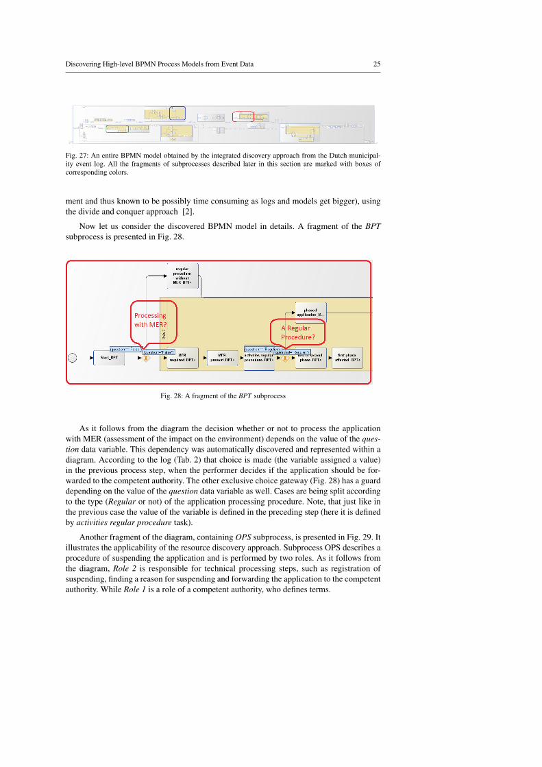
Now let us consider the discovered BPMN model in details. A fragment of the BPTsubprocess is presented in Fig. 28.
Fig. 28: A fragment of the BPT subprocess
As it follows from the diagram the decision whether or not to process the applicationwith MER (assessment of the impact on the environment) depends on the value of the ques-tion data variable. This dependency was automatically discovered and represented within adiagram. According to the log (Tab. 2) that choice is made (the variable assigned a value)in the previous process step, when the performer decides if the application should be for-warded to the competent authority. The other exclusive choice gateway (Fig. 28) has a guarddepending on the value of the question data variable as well. Cases are being split accordingto the type (Regular or not) of the application processing procedure. Note, that just like inthe previous case the value of the variable is defined in the preceding step (here it is definedby activities regular procedure task).
Another fragment of the diagram, containing OPS subprocess, is presented in Fig. 29. Itillustrates the applicability of the resource discovery approach. Subprocess OPS describes aprocedure of suspending the application and is performed by two roles. As it follows fromthe diagram, Role 2 is responsible for technical processing steps, such as registration ofsuspending, finding a reason for suspending and forwarding the application to the competentauthority. While Role 1 is a role of a competent authority, who defines terms.

26 A. A. Kalenkova et al.
Fig. 29: A fragment of the OPS subprocess
Figure 30 presents a fragment of EIND subprocess, constructed in case the event logwas enriched with additional cancel attributes.13 This subprocess describes the terminationprocedure. If the result of terminate on request task execution is true (it was decided toterminate the entire process), then the cancellation occurs and a token is produced to an out-going sequence flow marked with a corresponding boundary cancellation event, leading tothe final process task. Whereas it was decided not to terminate the entire process, subprocessEIND terminates normally and a token is produced to an ordinary outgoing sequence flowof the subprocess, resuming execution of the entire process.
Fig. 30: A subprocess with a cancellation event
6.1.2 Discovering a Booking Process
A real-life event log of a ticketing system was analyzed as well. This log contains 774 tracesand describes the behavior of a web-based system used for searching and booking flights.Each trace of the log represents the user interactions with the ticketing system. The usercan buy a flight and get an insurance. For that purpose he or she needs to fill the form withpersonal data, choose an insurance type, choose a type of payment, and pay.
A hierarchical BPMN diagram of the online booking process discovered from the eventlog contains subprocesses describing filling personal data, registration of insurance, andpayment procedures.
13Note that in the overall diagram (Fig. 27) the fragment of this subprocess is shown without cancellationevent.

Discovering High-level BPMN Process Models from Event Data 27
Fig. 31: A fragment of the filling personal data subpro-cess
A fragment of the filling personaldata subprocess is presented in Fig. 31.The resource perspective in the dia-gram shows that different groups ofusers perform different steps withinthe subprocesses. As it follows fromthis diagram there are two groups ofusers: the first group fills the forms inorder to buy a flight, while users fromthe other group just check/uncheck thedocument expiry date checkbox. Theother important observation is that theusers fill the form fields in an arbitraryorder: the parallel gateway splits thecontrol flow into several subflows, eachof which corresponds to a concrete filedof the personal data form.
6.1.3 Discovering a Banking Process
Fig. 32: A fragment of the service subprocess
Another event log being analyzed is asmall (66 traces) software log of a bank-ing information system, which consistsof three program layers (front, service,and database) and handles user requests.First, the user request is received by thefront layer and transmitted to the nextservice layer. The service layer imple-ments the business logics of the pro-cess, calling the database layer methodsto store and retrieve data. Each programlayer was represented as a subprocess.Fig. 32 shows a fragment of the service
layer, it contains an exclusive gateway with guards, identifying types of operations (typesof requests for a reference information) and passing the control to corresponding outgoingsequence flows.
6.2 Analyzing Discovered BPMN Models
In the previous subsection we have discussed the capability of the integrated discovery ap-proach to build relevant multiperspective BPMN diagrams from real-life event logs. Now letus consider behavioral and structural characteristics of BPMN models discovered from thereal-life event logs.
For the experiments we have chosen 7 real-life event logs: 5 event logs of building per-mit administrative processes of Dutch municipalities (denoted as M1-M5), an event log of aticketing system (TS), and an event log of a banking system (BS). These event logs are de-scribed in the subsections 6.1.1, 6.1.2, and 6.1.3 respectively. For mining data and resource

28 A. A. Kalenkova et al.
perspectives approaches [22] and [8] were used. To discover subprocesses all the eventlogs were preprocessed (the information needed for event localization was learned from theevent attributes) and then a discovery approach [4] was applied. The Inductive miner tech-nique [20] was used as an underlying control flow discovery method. The discovered Petrinets were converted to BPMN models using an algorithm presented in [16].
Since the aim of the work is to discover readable and convenient process models, theanalysis of their structural characteristics is meaningful. Next to these structural character-istics we need to estimate behavior parameters of the models to evaluate their quality withrespect to the initial event logs. In order to relate initial event logs and discovered processmodels, we consider three standard metrics: fitness, precision and generalization [1]. Fit-ness shows if the model can replay a given event log. If all the traces of the log can bereplayed by a model then the value of the fitness function is 1. If there are non-fitting traces,then corresponding alignments, represented as sequences of synchronous and asynchronoussteps performed to replay a trace on a model, are calculated and penalties are estimatedin such a way that the value of the fitness function will be decreased proportionally to thenumber of asynchronous log and model moves in the alignment. The detailed descriptionof fitness function can be found in [3]. In this work we calculate the fitness value for eachsubprocesses, using the approach presented in [26] and then take a weighted sum, wherecoefficients depend on the number of times subprocesses’ traces appear in the initial eventlog.
Having a fitting process model is not sufficient, because it is easy to construct a processmodel that can replay any trace, but that has no relation to the log. Thus, an additional pro-cess metric: precision is needed. The precision shows if the model does not allow too muchbehavior. The generalization metric indicates whether the model is general enough. We cal-culated precision and generalization metrics for the discovered Petri net models, replayingthe alignments. For the detailed descriptions of these metrics please refer to [5, 7]. Table 3presents the behavioral characteristics of the models discovered from the event logs.
Log Fitness Precision Genera-traces lization
M1 0.90 0.85 0.99M2 0.72 0.91 0.98M3 0.82 0.63 0.99M4 0.66 0.75 0.99M5 0.76 0.8 0.98TS 0.77 0.78 0.98BS 0.99 0.55 0.71
Table 3: Behavioral characteristics of processmodels discovered from the event logs
Structural metrics of process models highlycorrelate with their readability. The followingstructural metrics were considered during theanalysis of the discovered models: number ofnodes (including number tasks, XOR gateways,AND gateways, data objects, subprocesses, andswimlanes), number of control flows, density (ra-tio of the number of control flows to the pos-sible maximum number of control flows), diam-eter (the maximal shortest path from the startnode to a graph node), depth (maximal nesting ofthe graph), number of child nodes for compound
nodes. As it was statistically shown in [25], the number of nodes, density, diameter, anddepth have a negative correlation with the process model understandability. Thus, we wereespecially interested in these metrics. Structural metrics of the discovered process modelsare presented in Table 4.

Discovering High-level BPMN Process Models from Event Data 29
Number of Number of NumberLog tasks, Num- swim- Number of of data
traces XOR, AND ber of lanes child nodes Density Diameter Depth objectsgateways flows and sub- and
processes guards
M1 180, 24, 60 350 13, 14 124 / 1 / 12.8 0.003 35 / 4 / 10.6 3 2, 5M2 235, 49, 72, 2 482 11, 22 191 / 1 / 13.2 0.003 44 / 4/ 12.7 3 2, 3M3 238, 44, 66 494 10, 22 31 / 1 / 7.7 0.003 27 / 4/ 10.5 2 2, 6M4 265, 44, 72 504 14, 37 134 / 1 / 9.5 0.002 31 / 4 / 13.8 3 2, 5M5 255, 44, 88 512 13, 42 177 / 1 / 9.5 0.002 35 / 4 / 12.4 3 2, 3TS 59, 4, 20 134 6, 5 47 / 1 / 12.0 0.009 13 / 2 / 7.3 3 6, 4BS 74, 4, 10 159 4, 4 31 / 2 / 16 0.1 11 / 2 / 7.0 3 3, 4
Table 4: Structural characteristics of process models discovered from the event logs. 14
These structural characteristics of the discovered process models were compared withthe characteristics of the BPMN models constructed manually. For that reason the existingSigavio collection of 4781 BPMN models from various domains was analyzed. The resultsbased on the Signavio collection analysis are presented in Table 5. For each parameter max-imal, minimal and average values are specified.
Number of Number of Numbertasks, Num- swim- Number of of data
XOR, AND ber of lanes child nodes Density Diameter Depth objectsgateways flows and sub- and
processes guards
34/ 0/ 7.2, 38/ 0/ 14.6, 20/ 0/ 0.7416/ 0/ 2, 27/ 0/ 3.4 14/ 0/ 0.5 68/ 0/ 4.4 0.87/ 0/ 0.1 25/ 1/ 8 8/ 1/ 2.7 6 /0 /0.008
14/ 0/ 0.66
Table 5: Structural characteristics of BPMN models from the Signavio model collection.14
Although the total number of elements in the discovered process models is significantlyhigher that in manually created BPMN models, structural characteristics within containers(subprocesses and swimlanes), such as diameter (only for subprocesses) and number of childnodes, are comparable. Thus, an automatically discovered (sub)model within a subprocessor swimlane resembles manually created model by its structural characteristics. The maxi-mum values for the number of child nodes of the discovered BPMN models were typicallyfound in the main subprocesses whereas other subprocesses were comparable to the manu-ally created models. Thus, the results of the experiments show that the proper identificationof subprocesses helps to discover readable and convenient process models fully reflectingprocess behavior recorded in the event log. Moreover, the identification of subprocesses sig-nificantly reduce the time needed for discovery. Thus, it often takes less than a minute todiscover a BPMN model from any of the real-life event logs, while construction of BPMNmodels without identification of subprocesses cannot be performed in a reasonable amountof time.
14The maximal, minimal and average values are separated by a slash, the values of metrics for differenttypes of elements are separated by a comma.

30 A. A. Kalenkova et al.
7 Conclusion
In this paper we presented an approach to discover BPMN models from event logs leverag-ing the representational bias of BPMN. The models discovered cover multiple perspectives(next to control-flow also resources and data) and, if possible, have a meaningful hierar-chy to improve their readability. The approach was implemented in ProM and resulted in aplug-in where multi-perspective hierarchical process models can be learned in a single step.
The overall approach can be summarized as follows. First the event log is split intosmaller event logs. As demonstrated it is often possible to exploit domain knowledge, eventand case attributes to create localized event logs. A labeled Petri net is learned per sublogand the projected log is replayed on these individual generally much smaller labeled Petrinets. Through replay we can add information on input and output data and we can even learnguards. The resulting data Petri net can be converted to a BPMN model and also resourceinformation can be added. This results in a hierarchical BPMN model that integrates thedifferent perspectives.
The work was tested on several real-life event logs. The results were evaluated usingvarious metrics and compared with a collection of standard BPMN models. The resultsindicate that the models are of good quality and definitely better than models obtained usingan approach that does not consider hierarchy. An added bonus is that the splitting of the logsalso improves performance.
This paper consolidates various lines of research done earlier. However, the differentresults were never integrated and important steps were missing to go from an event logto a multi-perspective hierarchical BPMN model. Note that wherever possible we madethe approach pluggable. For example, one can use any discovery technique to discover thecontrol-flow of the subprocesses.
Future work aims at finding structural differences between discovered BPMN models(as-is) and reference BPMN models (to-be) using the model comparison tool proposed ear-lier [15].
References
1. van der Aalst, W.: Process Mining: Discovery, Conformance and Enhancement of Busi-ness Processes. Springer-Verlag, Berlin (2011)
2. van der Aalst, W.: A General Divide and Conquer Approach for Process Mining. In:Federated Conference on Computer Science and Information Systems (FedCSIS 2013),pp. 1–10. IEEE Computer Society (2013)
3. van der Aalst, W., Adriansyah, A., van Dongen, B.: Replaying History on ProcessModels for Conformance Checking and Performance Analysis. Wiley Int. Rev. DataMin. and Knowl. Disc. 2(2), 182–192 (2012). DOI 10.1002/widm.1045. URLhttp://dx.doi.org/10.1002/widm.1045
4. van der Aalst, W., Kalenkova, A., Rubin, V., Verbeek, E.: Process Discovery UsingLocalized Events. In: Application and Theory of Petri Nets and Concurrency, LectureNotes in Computer Science, vol. 9115, pp. 287–308. Springer International Publishing(2015)
5. Adriansyah, A., Munoz-Gama, J., Carmona, J., van Dongen, B., van der Aalst, W.:Alignment Based Precision Checking. In: Workshop on Business Process Intelligence(BPI 2012). Tallinn, Estonia (2012)

Discovering High-level BPMN Process Models from Event Data 31
6. Buijs, J., van Dongen, B., van der Aalst, W.: A Genetic Algorithm for DiscoveringProcess Trees. In: IEEE Congress on Evolutionary Computation (CEC 2012), pp. 1–8.IEEE Computer Society (2012)
7. Buijs, J., van Dongen, B., van der Aalst, W.: On the Role of Fitness, Precision, Gener-alization and Simplicity in Process Discovery. In: OTM Federated Conferences, 20thInternational Conference on Cooperative Information Systems (CoopIS 2012), LectureNotes in Computer Science, vol. 7565, pp. 305–322. Springer-Verlag, Berlin (2012)
8. Burattin, A., Sperduti, A., Veluscek, M.: Business Models Enhancement ThroughDiscovery of Roles. In: IEEE Symposium on Computational Intelligence and DataMining, CIDM 2013, Singapore, 16-19 April, 2013, pp. 103–110 (2013). DOI10.1109/CIDM.2013.6597224
9. Conforti, R., Dumas, M., García-Bañuelos, L., La Rosa, M.: Business Process Manage-ment: 12th International Conference, BPM 2014, Haifa, Israel, September 7-11, 2014.Proceedings, chap. Beyond Tasks and Gateways: Discovering BPMN Models with Sub-processes, Boundary Events and Activity Markers, pp. 101–117. Springer (2014). DOI10.1007/978-3-319-10172-9_7
10. De Weerdt, J., van den Broucke, S.K., Caron, F.: Bidimensional Process Discovery forMining BPMN Models. In: Business Process Management Workshops, pp. 529–540.Springer (2014)
11. Dijkman, R., Dumas, M., Ouyang, C.: Semantics and Analysis of Business ProcessModels in BPMN. Information & Software Technology 50(12), 1281–1294 (2008)
12. van Dongen;, B.: Bpi challenge 2015 (2015). DOIhttp://dx.doi.org/10.4121/uuid:31a308ef-c844-48da-948c-305d167a0ec1
13. van Dongen, B., Medeiros, A., Verbeek, H., Weijters, A., van der Aalst, W.: The ProMframework: A New Era in Process Mining Tool Support. In: Application and Theory ofPetri Nets 2005, Lecture Notes in Computer Science, vol. 3536, pp. 444–454. Springer-Verlag, Berlin (2005)
14. García-Bañuelos, L., van Beest, N., Dumas, M., Rosa, M.L.: Complete andInterpretable Conformance Checking of Business Processes (2015). URLhttp://eprints.qut.edu.au/91552/
15. Ivanov, S., Kalenkova, A., van der Aalst, W.: BPMNDiffViz: A Tool for BPMN ModelsComparison. In: Proceedings of the BPM Demo Session 2015 Co-located with the 13thInternational Conference on Business Process Management (BPM 2015), Innsbruck,Austria, September 2, 2015., pp. 35–39 (2015)
16. Kalenkova, A., van der Aalst, W., Lomazova, I., Rubin, V.: Process Mining UsingBPMN: Relating Event Logs and Process Models. Software and Systems Modelingpp. 1–30 (2015)
17. Kalenkova, A., de Leoni, M., van der Aalst, W.: Discovering, Analyzing and EnhancingBPMN Models Using ProM. In: Business Process Management - 12th InternationalConference, BPM 2014, Haifa, Israel, September 7-11, 2014. Proceedings (2014)
18. Kheldoun, A., Barkaoui, K., Ioualalen, M.: Specification and Verification of ComplexBusiness Processes - A High-Level Petri Net-Based Approach. In: BPM, Lecture Notesin Computer Science, vol. 9253, pp. 55–71. Springer (2015)
19. Leemans, S., Fahland, D., van der Aalst, W.: Discovering Block-structured ProcessModels from Event Logs: A Constructive Approach. In: J. Colom, J. Desel (eds.) Appli-cations and Theory of Petri Nets 2013, Lecture Notes in Computer Science, vol. 7927,pp. 311–329. Springer-Verlag, Berlin (2013)
20. Leemans, S., Fahland, D., van der Aalst, W.: Discovering Block-Structured ProcessModels from Incomplete Event Logs. In: Application and Theory of Petri Nets and

32 A. A. Kalenkova et al.
Concurrency, Lecture Notes in Computer Science, vol. 8489, pp. 91–110. Springer In-ternational Publishing (2014)
21. Lengauer, T., Tarjan, R.: A Fast Algorithm for Finding Dominators in a Flowgraph.ACM Trans. Program. Lang. Syst. 1(1), 121–141 (1979). DOI 10.1145/357062.357071
22. de Leoni, M., van der Aalst, W.: Data-aware process mining: Discovering decisions inprocesses using alignments. In: Proceedings of the 28th Annual ACM Symposium onApplied Computing, SAC ’13, Coimbra, Portugal, March 18-22, 2013, pp. 1454–1461(2013). DOI 10.1145/2480362.2480633
23. Muehlen, M., Recker, J.: How Much Language Is Enough? Theoretical and PracticalUse of the Business Process Modeling Notation. In: Proceedings of the 20th Interna-tional Conference on Advanced Information Systems Engineering (CAiSE’08), LectureNotes in Computer Science, vol. 5074, pp. 465–479. Springer-Verlag, Berlin (2008)
24. OMG: Business Process Model and Notation (BPMN). Object Management Group,formal/2013-12-09 (2013)
25. Sánchez-González, L., García, F., Mendling, J., Ruiz, F., Piattini, M.: Prediction ofBusiness Process Model Quality Based on Structural Metrics. In: ER, Lecture Notesin Computer Science, vol. 6412, pp. 458–463. Springer (2010)
26. Verbeek, H., van der Aalst, W.: Merging Alignments for Decomposed Replay. In:Application and Theory of Petri Nets and Concurrency: 37th International Confer-ence, PETRI NETS 2016, Torun, Poland, June 19-24, 2016. Proceedings, pp. 219–239.Springer International Publishing, Cham (2016). DOI 10.1007/978-3-319-39086-4_14
27. Ye, J., Sun, S., Song, W., Wen, L.: Formal Semantics of BPMN Process Models UsingYAWL. In: Intelligent Information Technology Application, 2008. IITA ’08. SecondInternational Symposium on, vol. 2, pp. 70–74 (2008). DOI 10.1109/IITA.2008.68