discovering nontrivial and functional behavior in register machines
TRANSCRIPT

Discovering Nontrivial and Functional Behavior in Register Machines
Anthony Joseph
Past StudentUniversity of Technology [email protected]
Nontrivial and functional behavior in register machines is examined.Register machines are simple implementations of modern informationand communications technology and provide a computationally simplevehicle for investigating examples of nontrivial and functional behav-ior. They also provide opportunities for optimizing information andcommunication technologies to use fewer resources or perform func-tions more quickly.
A simple two-register, four-instruction register machine was ana-lyzed using soft and hard analytical techniques. Examples of nontrivialand functional behavior were identified by observing two-register, four-instruction register machines with various initial conditions. These reg-ister machines were identified by an exhaustive search of all possibleregister machine configurations meeting a particular definition. A subse-quent investigation into the randomness in register machine compo-nents involved a frequency analysis, comparing program counter andregister values against the discrete uniform distribution.
It is possible to observe examples of cyclical and conditional behav-ior, register-dependent and register-independent behavior, randomnessin the register machine’s program counter and registers, and foundationarithmetic functions. Further analysis of this register machine configura-tion yields opportunities for synthesizing multiple functions into a sin-gle register machine and optimizing functional register machines bybrute-force testing all possible register machines.
1. Introduction
Register machines are implementations of a simple computing devicethat perform operations on a fixed set of data registers. According toStephen Wolfram, register machines are “specifically designed to bevery simple idealizations of present-day computers” [1, p. 97]. There-fore, all modern information and communication technologies useregister machines of various implementations to store, access, and ma-nipulate data. Register machines are comprised of three related com-ponents: a register, a program, and a program counter.
Complex Systems, 22 © 2013 Complex Systems Publications, Inc.

1.1 RegisterA register, or set of registers with a constant width, stores an encodedvalue. The horizontal axis (1 to 8) indicates the value of the registerand the vertical axis (1 to 31) indicates the number of instructions exe-cuted in the program. Red-colored register values indicate that a valuehigher than the register’s width is currently stored in that register.This is similar to the concept of “arithmetic overflow,” where the re-sult of a calculation is greater than the register that stores or repre-sents the data. Unlike some physical implementations of a register ma-chine such as a microcontroller, microprocessor, or other low-levelhardware devices, exceeding a register’s capacity will not clear the reg-ister’s value or halt the register machine. Figure 1 shows an exampleof a single register.
1 2 3 4 5 6 7 8
1
10
20
31
1 2 3 4 5 6 7 8
1
10
20
31
register: 2
Figure 1. Register example.
1.2 ProgramA program describes the behavior of the register machine. Programsare a set of instructions that operate on registers. There are a widevariety of implementations of instructions that are available on differ-ent hardware platforms. Wolfram uses a simple implementation withtwo instructions [1, p. 97]:
† an increment operation, which increases the value of the register by oneand then executes the next instruction in the program, and
102 A. Joseph
Complex Systems, 22 © 2013 Complex Systems Publications, Inc.

† a decrement-jump operation, which decreases the value of a register byone and “jumps” to another instruction in the program. If the registervalue is 0, then the program executes the next instruction. The decre-ment-jump operation is the main operation that yields nontrivialbehavior.
In both cases, an instruction contains:
† the current instruction identified as an integer,
† the next instruction to be executed,
† the register that is being manipulated, and
† the modifier being applied (i.e., 1 for an increment operation and -1for a decrement operation).
The author used a Minsky register machine implementation [2],which is available via the Wolfram Demonstrations Project [3]. Thisimplementation is based on Wolfram’s implementation [1, p. 98] withthe added instruction of a “halted instruction,” where a programwould stop execution when it completed execution.
A no-operation “NOP” can be included but is not consideredwithin this study, as “any NOP instruction can be removed from theformal description of the underlying Minsky register machine withoutaltering its function” [2]. Therefore, including the halted instructionwill allow the discovery of any possible arithmetic or logical functionsas the register machine should halt after it has performed its function.
Unfortunately, there are no standard representations for registermachines. Wolfram [1, p. 98] used as a representation a sequence ofsquares with directional arrowheads, arrows, and color to define theinstruction and whether an increment or decrement jump operation isperformed—the destination register for a decrement-jump operationand the register to be operated on, respectively. The author has used aMealy finite state machine representation to describe these programsas described in Figure 2 using the nomenclature in Figures 3 to 6.
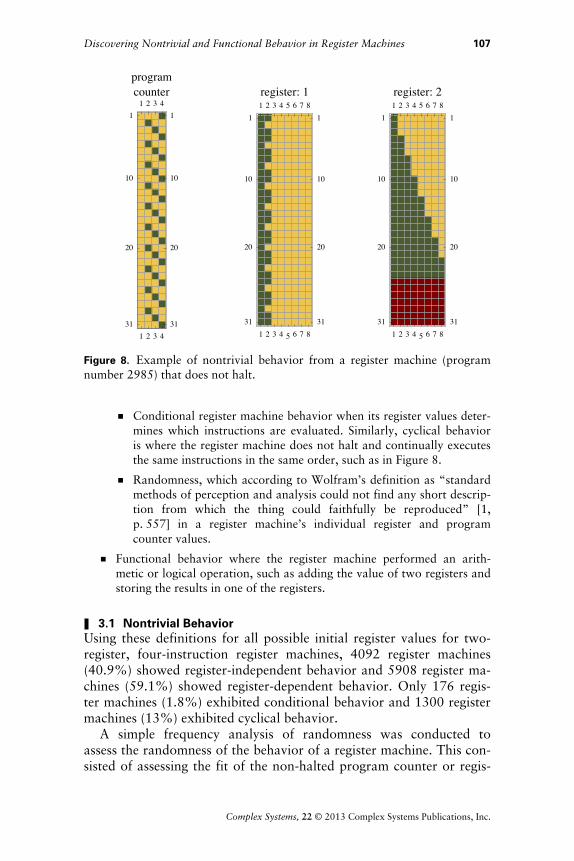
1.3 Program CounterA program counter indicates the instruction that is executed at a par-ticular time. The horizontal axis (1 to 4) indicates the instructionexecuted and the vertical axis (1 to 21) indicates the number of in-structions executed in the program. Figure 7 shows an example of aprogram counter.
An enumeration is used to describe all unique register machine pro-grams and is described in Appendix A. All of the register machinesspecified in this paper can be simulated using [3].
Discovering Nontrivial and Functional Behavior in Register Machines 103
Complex Systems, 22 © 2013 Complex Systems Publications, Inc.

R:1, -1
R:1, 1
R:2, 1
R:1, -1
R:1, 0
1
2
3
4
5
Figure 2. Program example: program number 2984.
2
Figure 3. Program nomenclature: an instruction.
R:2, 1
2
3
Figure 4. Program nomenclature: an increment instruction number 2 adds 1bit to register 2 and then executes instruction 3.
R:2, -1
45
Figure 5. Program nomenclature: a decrement-jump instruction number 4,where if the value of register 2 is not 0 then 1 bit is subtracted from register 2and instruction 4 is executed again. Otherwise, if the value of register 2 is 0,then instruction 5 is executed.
104 A. Joseph
Complex Systems, 22 © 2013 Complex Systems Publications, Inc.
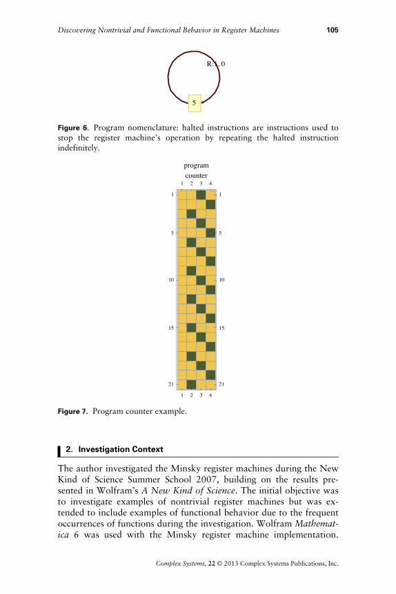
R:1, 0
5
Figure 6. Program nomenclature: halted instructions are instructions used tostop the register machine’s operation by repeating the halted instructionindefinitely.
1 2 3 4
1
5
10
15
21
1 2 3 4
1
5
10
15
21
programcounter
Figure 7. Program counter example.
2. Investigation Context
The author investigated the Minsky register machines during the NewKind of Science Summer School 2007, building on the results pre-sented in Wolfram’s A New Kind of Science. The initial objective wasto investigate examples of nontrivial register machines but was ex-tended to include examples of functional behavior due to the frequentoccurrences of functions during the investigation. Wolfram Mathemat-ica 6 was used with the Minsky register machine implementation.
Discovering Nontrivial and Functional Behavior in Register Machines 105
Complex Systems, 22 © 2013 Complex Systems Publications, Inc.

y g p
Due to time and hardware limitations, the author only studied regis-ter machines with two registers with 8 bits in width and programswith four instructions with a program execution time of 50 instruc-tions. Fifty instructions was chosen to avoid the halting problem: if aprogram did not halt after 50 instructions, then it was assumed tonever halt.
The number of possible register machine programs (similar in con-cept to “rules” in cellular automata theory) is calculated by HrHi + 1LLi,where i is the number of instructions and r is the number of registers.This definition is described in further detail in Appendix A. With thisconfiguration, there are 10 000 possible programs to study.
The author observed every possible four-instruction, two-registerconfiguration program with various initial program counters and reg-ister values. For example, if two registers have initial values of 2 and4 respectively and final values of 6 and 0 respectively, then the pro-gram may yield an addition function and would merit further investi-gation. Similarly, if the registers or program counters yielded nontriv-ial behavior, then the program was analyzed further. A subsequent,exhaustive analysis of all possible four-instruction, two-register ma-chines that assessed a register machine against formal definitions ofnontrivial and functional behavior was performed, with the resultsdocumented in Section 3. It required approximately 24 hours of con-tinuous processing time on an Apple MacBook, late-2008 editionwith a 2.4 GHz dual-core processor and 4GB of RAM running twoMathematica 8.0.4 kernels.
3. Observations
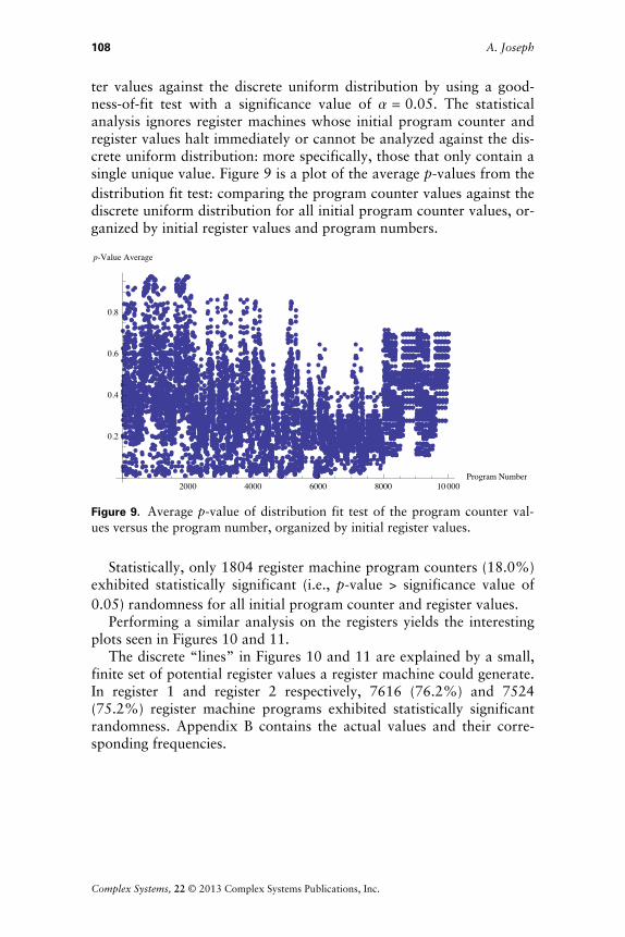
The author observed that with the Minsky register machine, 8700 reg-ister machines (87%) reached a halted state and therefore achieved afunction. However, this does not imply that nontrivial behavior can-not be observed from register machines that do not halt, such as theexample register machine 2985 shown in Figure 8.
Many of the register machines exhibited the following behaviors.
† Nontrivial behavior that included register-independent and register-dependent behavior, conditional and cyclical behavior, and randomnessin register machine components where:
† Register-dependent register machines halt in at least one instructiondue to at least one register having a zero value for any initial registervalue, while register-independent behavior involves a register ma-chine not halting for any initial register value.
106 A. Joseph
Complex Systems, 22 © 2013 Complex Systems Publications, Inc.
1 2 3 4
1
10
20
31
1 2 3 41
10
20
31
programcounter
1 2 3 4 5 6 7 8
1
10
20
31
1 2 3 4 5 6 7 81
10
20
31
register: 1
1 2 3 4 5 6 7 8
1
10
20
31
1 2 3 4 5 6 7 81
10
20
31
register: 2
Figure 8. Example of nontrivial behavior from a register machine (programnumber 2985) that does not halt.
† Conditional register machine behavior when its register values deter-mines which instructions are evaluated. Similarly, cyclical behavioris where the register machine does not halt and continually executesthe same instructions in the same order, such as in Figure 8.
† Randomness, which according to Wolfram’s definition as “standardmethods of perception and analysis could not find any short descrip-tion from which the thing could faithfully be reproduced” [1,p.!557] in a register machine’s individual register and programcounter values.
† Functional behavior where the register machine performed an arith-metic or logical operation, such as adding the value of two registers andstoring the results in one of the registers.
3.1 Nontrivial BehaviorUsing these definitions for all possible initial register values for two-register, four-instruction register machines, 4092 register machines(40.9%) showed register-independent behavior and 5908 register ma-chines (59.1%) showed register-dependent behavior. Only 176 regis-ter machines (1.8%) exhibited conditional behavior and 1300 registermachines (13%) exhibited cyclical behavior.
A simple frequency analysis of randomness was conducted toassess the randomness of the behavior of a register machine. This con-sisted of assessing the fit of the non-halted program counter or regis-
Discovering Nontrivial and Functional Behavior in Register Machines 107
Complex Systems, 22 © 2013 Complex Systems Publications, Inc.
g p g g
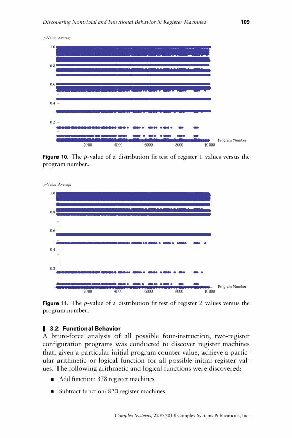
ter values against the discrete uniform distribution by using a good-ness-of-fit test with a significance value of a = 0.05. The statisticalanalysis ignores register machines whose initial program counter andregister values halt immediately or cannot be analyzed against the dis-crete uniform distribution: more specifically, those that only contain asingle unique value. Figure 9 is a plot of the average p-values from thedistribution fit test: comparing the program counter values against thediscrete uniform distribution for all initial program counter values, or-ganized by initial register values and program numbers.
2000 4000 6000 8000 10000Program Number
0.2
0.4
0.6
0.8
p-Value Average
Figure 9. Average p-value of distribution fit test of the program counter val-ues versus the program number, organized by initial register values.
Statistically, only 1804 register machine program counters (18.0%)exhibited statistically significant (i.e., p-value > significance value of0.05) randomness for all initial program counter and register values.
Performing a similar analysis on the registers yields the interestingplots seen in Figures 10 and 11.
The discrete “lines” in Figures 10 and 11 are explained by a small,finite set of potential register values a register machine could generate.In register 1 and register 2 respectively, 7616 (76.2%) and 7524(75.2%) register machine programs exhibited statistically significantrandomness. Appendix B contains the actual values and their corre-sponding frequencies.
108 A. Joseph
Complex Systems, 22 © 2013 Complex Systems Publications, Inc.
2000 4000 6000 8000 10000Program Number
0.2
0.4
0.6
0.8
1.0
p-Value Average
Figure 10. The p-value of a distribution fit test of register 1 values versus theprogram number.
2000 4000 6000 8000 10000Program Number
0.2
0.4
0.6
0.8
1.0
p-Value Average
Figure 11. The p-value of a distribution fit test of register 2 values versus theprogram number.
3.2 Functional BehaviorA brute-force analysis of all possible four-instruction, two-registerconfiguration programs was conducted to discover register machinesthat, given a particular initial program counter value, achieve a partic-ular arithmetic or logical function for all possible initial register val-ues. The following arithmetic and logical functions were discovered:
† Add function: 378 register machines
† Subtract function: 820 register machines
Discovering Nontrivial and Functional Behavior in Register Machines 109
Complex Systems, 22 © 2013 Complex Systems Publications, Inc.
† Multiplication function: 31 register machines
† Divide function: 48 register machines, of which four performed the di-vide operation and 44 performed the divide operation and added the re-sult to an existing register value
† Clear function: 5168 register machines cleared the first register, 5168registers cleared the second register, and 2330 register machines clearedboth registers
Appendix C contains a list of the register machines that performedthese mathematical functions.
4. Register Machine Examples
4.1 Nontrivial Behavior4.1.1 Register-Dependent and Register-Independent Behavior
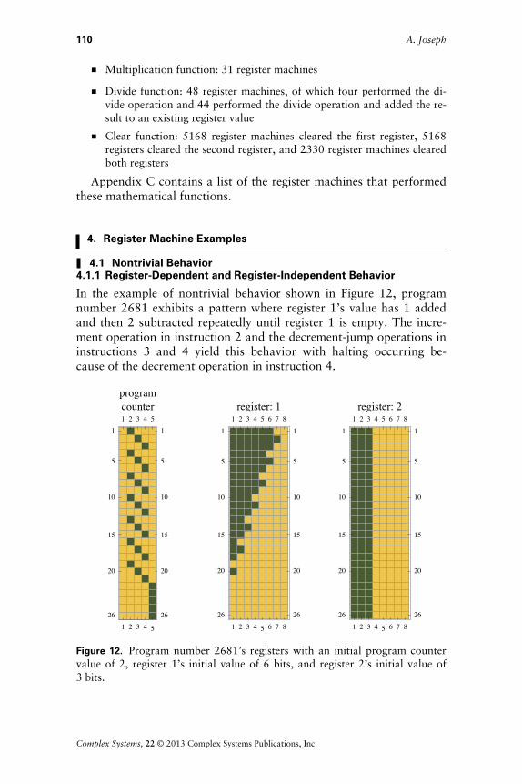
In the example of nontrivial behavior shown in Figure 12, programnumber 2681 exhibits a pattern where register 1’s value has 1 addedand then 2 subtracted repeatedly until register 1 is empty. The incre-ment operation in instruction 2 and the decrement-jump operations ininstructions 3 and 4 yield this behavior with halting occurring be-cause of the decrement operation in instruction 4.
1 2 3 4 5
1
5
10
15
20
26
1 2 3 4 51
5
10
15
20
26
programcounter
1 2 3 4 5 6 7 8
1
5
10
15
20
26
1 2 3 4 5 6 7 81
5
10
15
20
26
register: 1
1 2 3 4 5 6 7 8
1
5
10
15
20
26
1 2 3 4 5 6 7 81
5
10
15
20
26
register: 2
Figure 12. Program number 2681’s registers with an initial program countervalue of 2, register 1’s initial value of 6 bits, and register 2’s initial value of3!bits.
110 A. Joseph
Complex Systems, 22 © 2013 Complex Systems Publications, Inc.

The example shown in Figure 13 is very similar to the exampleshown in Figure 12, except in this case register 2’s value has 2 bitsadded and then 1 bit subtracted repeatedly. This example is of signifi-cance as it is structurally similar to Figure 12, but it does not halt.This is due to the infinite loop caused by instructions 2 and 4, whichincrement and decrement the same register and never activate thedecrement case where register 1 is equal to 0.
1 2 3 4
1
5
10
15
20
26
1 2 3 41
5
10
15
20
26
programcounter
1 2 3 4 5 6 7 8
1
5
10
15
20
26
1 2 3 4 5 6 7 81
5
10
15
20
26
register: 1
1 2 3 4 5 6 7 8
1
5
10
15
20
26
1 2 3 4 5 6 7 81
5
10
15
20
26
register: 2
Figure 13. Program number 2881’s registers with an initial program countervalue of 2, register 1’s initial value of 2 bits, and register 2’s initial value of4!bits.
The example in Figure 14 shows a non-halting register machinethat does not cause an overflow in any register.
These programs are of interest as they exhibit register-independentbehavior. The example program in Figure 15 exhibits register-depen-dent behavior: with an initial program counter value of 1, register 1 iscleared and then register 2 is cleared while incrementing and decre-menting register 1. However, if the program counter is initialized at 2,register 2 is cleared while incrementing and decrementing register 1’svalue.
Discovering Nontrivial and Functional Behavior in Register Machines 111
Complex Systems, 22 © 2013 Complex Systems Publications, Inc.

1 2 3 4
1
10
20
31
1 2 3 41
10
20
31
programcounter
1 2 3 4 5 6 7 8
1
10
20
31
1 2 3 4 5 6 7 81
10
20
31
register: 1
1 2 3 4 5 6 7 8
1
10
20
31
1 2 3 4 5 6 7 81
10
20
31
register: 2
Figure 14. Program number 3691’s registers with an initial program countervalue of 2, register 1’s initial value of 4 bits, and register 2’s initial value of6!bits.
1 2 3 4 5
1
10
20
31
1 2 3 4 51
10
20
31
programcounter
1 2 3 4 5 6 7 8
1
10
20
31
1 2 3 4 5 6 7 81
10
20
31
register: 1
1 2 3 4 5 6 7 8
1
10
20
31
1 2 3 4 5 6 7 81
10
20
31
register: 2
Figure 15. Program number 3680’s registers with an initial program countervalue of 1, register 1’s initial value of 4 bits, and register 2’s initial value of6!bits.
112 A. Joseph
Complex Systems, 22 © 2013 Complex Systems Publications, Inc.

4.1.2 Conditional and Cyclical Behavior
There are other examples of register machines that not only exhibitnontrivial behavior but also exhibit conditional behavior, where theregister machine’s behavior depends on certain conditions being satis-fied. These conditions usually involve a register being set to 0 and aprogram using a decrement-jump operation to yield nontrivial behav-ior. For the program number 386, starting the program at differentinitial program counter values yields a variety of behaviors (imagesare shown in Appendix D):
† If register 1 has an odd value and the initial program counter value is 1,then the program clears the value of register 1 and halts without alter-ing register 2. Similarly, if register 1 has an even number and the initialprogram counter value is 4, then the program clears the value of regis-ter 1 without altering register 2. This is caused by the fact that instruc-tion 4 is the last instruction to be executed when register 1 is empty, sothe program halts.
† If the initial program counter value is 2 with an even number stored inregister 2, then the program adds the value of register 2 plus 1 to regis-ter 1 (i.e., register 1’s value = register 1’s initial value + register 2’s ini-tial value + 1), then clears register 1. This is similar to the previouscase, as instruction 4 is the last instruction to be executed when the reg-ister machine halts after clearing register 1.
† However, if the last instruction to be executed in the last decrement op-eration was instruction 1, then the register machine enters an infiniteloop, continuously incrementing and decrementing register 1’s value asshown in Appendix D. Similar behavior is observed for initializing thisregister machine at an initial program counter value of 3 or 4.
Another example of conditional behavior is program number5169. This program:
† subtracts the initial value of register 1 from register 2,
† clears register 1, and
† oscillates between (register 1’s initial value - register 2’s initial value)and (register 1’s initial value - register 2’s initial value - 1).
In Figure 16, as register 1’s initial value is 4 and register 2’s initialvalue is 6, then register 2’s final register value oscillates between 1and 2.
4.1.3 Randomness in a Register Machine’s Program Counter
Program number 1274 is an example of randomness in a register ma-chine’s program counter; this program subtracts the value of regis-ter!2 from register 1 and stores the result in register 1 as shown inFigure!17.
Discovering Nontrivial and Functional Behavior in Register Machines 113
Complex Systems, 22 © 2013 Complex Systems Publications, Inc.

1 2 3 4
1
5
10
15
20
26
1 2 3 41
5
10
15
20
26
programcounter
1 2 3 4 5 6 7 8
1
5
10
15
20
26
1 2 3 4 5 6 7 81
5
10
15
20
26
register: 1
1 2 3 4 5 6 7 8
1
5
10
15
20
26
1 2 3 4 5 6 7 81
5
10
15
20
26
register: 2
Figure 16. Program number 5169’s registers with an initial program countervalue of 2, register 1’s initial value of 4 bits, and register 2’s initial value of6!bits.
1 2 3 4 5
1
10
20
31
1 2 3 4 51
10
20
31
programcounter
1 2 3 4 5 6 7 8
1
10
20
31
1 2 3 4 5 6 7 81
10
20
31
register: 1
1 2 3 4 5 6 7 8
1
10
20
31
1 2 3 4 5 6 7 81
10
20
31
register: 2
Figure 17. Program number 1274’s registers with an initial program countervalue of 4, register 1’s initial value of 6 bits, and register 2’s initial value of4!bits.
114 A. Joseph
Complex Systems, 22 © 2013 Complex Systems Publications, Inc.

However, under specific circumstances, such as register 2’s initialvalue being 1 bit greater than register 1’s value, the program counterexhibits a different kind of randomness, as shown in Figure 18.
1 2 3 4 5
1
10
20
31
1 2 3 4 51
10
20
31
programcounter
1 2 3 4 5 6 7 8
1
10
20
31
1 2 3 4 5 6 7 81
10
20
31
register: 1
1 2 3 4 5 6 7 8
1
10
20
31
1 2 3 4 5 6 7 81
10
20
31
register: 2
Figure 18. Program number 1274’s registers with an initial program countervalue of 4, register 1’s initial value of 6 bits, and register 2’s initial value of4!bits.
4.1.4 Randomness in a Register Machine’s Registers
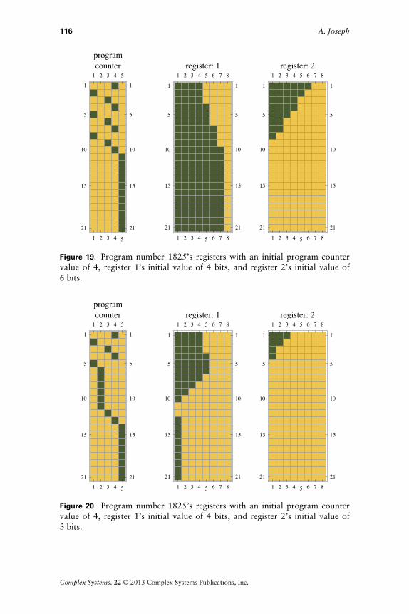
Figures 19 and 20 are two examples of randomness in a register ma-chine’s registers.
† Program number 1825 appears to have two distinct functions:
† If register 2’s value is even, then the value of register 2 is divided by2, the result is added to register 1, and the program halts.
† If register 2’s value is odd, then the value of register 2 is divided by2 and the integer component of the result is added to register 1; thenregister 1 is cleared and incremented, and then the program halts.
While the behavior of this register machine can be easily explained,such a large variance in its behavior warranted its inclusion in a studyon randomness in register machines.
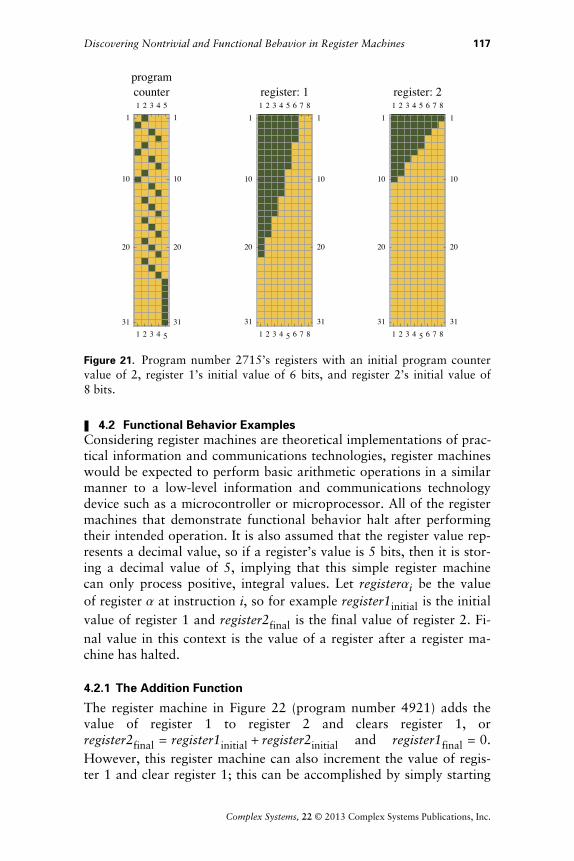
† Program number 2715 is a functionally simple register machine thatclears both registers. The way it clears registers is not simple. Register 2clears 3 bits and then clears 1 bit from register 1 until register 2 isempty, and then register 1 has 1 bit cleared after every three instruc-tions. Figure 21 shows how the register machine performs this behaviorunder different initial conditions.
Discovering Nontrivial and Functional Behavior in Register Machines 115
Complex Systems, 22 © 2013 Complex Systems Publications, Inc.
1 2 3 4 5
1
5
10
15
21
1 2 3 4 5
1
5
10
15
21
programcounter
1 2 3 4 5 6 7 8
1
5
10
15
21
1 2 3 4 5 6 7 8
1
5
10
15
21
register: 1
1 2 3 4 5 6 7 8
1
5
10
15
21
1 2 3 4 5 6 7 8
1
5
10
15
21
register: 2
Figure 19. Program number 1825’s registers with an initial program countervalue of 4, register 1’s initial value of 4 bits, and register 2’s initial value of6!bits.
1 2 3 4 5
1
5
10
15
21
1 2 3 4 5
1
5
10
15
21
programcounter
1 2 3 4 5 6 7 8
1
5
10
15
21
1 2 3 4 5 6 7 8
1
5
10
15
21
register: 1
1 2 3 4 5 6 7 8
1
5
10
15
21
1 2 3 4 5 6 7 8
1
5
10
15
21
register: 2
Figure 20. Program number 1825’s registers with an initial program countervalue of 4, register 1’s initial value of 4 bits, and register 2’s initial value of3!bits.
116 A. Joseph
Complex Systems, 22 © 2013 Complex Systems Publications, Inc.
1 2 3 4 5
1
10
20
31
1 2 3 4 51
10
20
31
programcounter
1 2 3 4 5 6 7 8
1
10
20
31
1 2 3 4 5 6 7 81
10
20
31
register: 1
1 2 3 4 5 6 7 8
1
10
20
31
1 2 3 4 5 6 7 81
10
20
31
register: 2
Figure 21. Program number 2715’s registers with an initial program countervalue of 2, register 1’s initial value of 6 bits, and register 2’s initial value of8!bits.
4.2 Functional Behavior ExamplesConsidering register machines are theoretical implementations of prac-tical information and communications technologies, register machineswould be expected to perform basic arithmetic operations in a similarmanner to a low-level information and communications technologydevice such as a microcontroller or microprocessor. All of the registermachines that demonstrate functional behavior halt after performingtheir intended operation. It is also assumed that the register value rep-resents a decimal value, so if a register’s value is 5 bits, then it is stor-ing a decimal value of 5, implying that this simple register machinecan only process positive, integral values. Let registerai be the valueof register a at instruction i, so for example register1initial is the initialvalue of register 1 and register2final is the final value of register 2. Fi-nal value in this context is the value of a register after a register ma-chine has halted.
4.2.1 The Addition Function
The register machine in Figure 22 (program number 4921) adds thevalue of register 1 to register 2 and clears register 1, orregister2final = register1initial + register2initial and register1final = 0.However, this register machine can also increment the value of regis-ter 1 and clear register 1; this can be accomplished by simply starting
Discovering Nontrivial and Functional Behavior in Register Machines 117
Complex Systems, 22 © 2013 Complex Systems Publications, Inc.

g p y p y gprogram number 4921 with an initial program counter value of 1. SeeAppendix D for examples of other addition functions.
1 2 3 4 5
1
5
10
15
20
26
1 2 3 4 51
5
10
15
20
26
programcounter
1 2 3 4 5 6 7 8
1
5
10
15
20
26
1 2 3 4 5 6 7 81
5
10
15
20
26
register: 1
1 2 3 4 5 6 7 8
1
5
10
15
20
26
1 2 3 4 5 6 7 81
5
10
15
20
26
register: 2
Figure 22. Program number 4921’s registers with an initial program countervalue of 4, register 1’s initial value of 3 bits, and register 2’s initial value of4!bits. The result of adding register 1’s value to register 2 and clearing regis-ter!1 is that register 1’s final value is 0 and register 2’s final value is 7.
4.2.2 The Subtraction Function
In program number 4721, register 2’s value is subtracted from regis-ter 1 and register 1 is cleared, or
register2final = Maxregister2initial - register1initial
0and
register1final = 0.
The maximum function is required, as this register machine assumesthere is no way to represent negative values (see Figure 23).
Similar behavior can be observed from Figure 22, where setting theprogram counter’s initial value to 1 decrements register 2’s value andclears register 1.
4.2.3 The Multiplication Function
Program number 3882, shown in Figures 24 and 25, represents a reg-ister machine that doubles the value of register 2 and adds it to regis-ter 1, clearing register 2 in the process. While multiplication can beperformed by repeatedly adding the value of one register to another,
118 A. Joseph
Complex Systems, 22 © 2013 Complex Systems Publications, Inc.
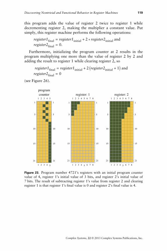
p y p y g g this program adds the value of register 2 twice to register 1 whiledecrementing register 2, making the multiplier a constant value. Putsimply, this register machine performs the following operations:
register1final = register1initial + 2 * register2initial andregister2final = 0.
Furthermore, initializing the program counter at 2 results in theprogram multiplying one more than the value of register 2 by 2 andadding the result to register 1 while clearing register 2, so
register1final = register1initial + 2 Iregister2initial + 1M and register2final = 0
(see Figure 26).
1 2 3 4 5
1
5
10
15
21
1 2 3 4 5
1
5
10
15
21
programcounter
1 2 3 4 5 6 7 8
1
5
10
15
21
1 2 3 4 5 6 7 8
1
5
10
15
21
register: 1
1 2 3 4 5 6 7 8
1
5
10
15
21
1 2 3 4 5 6 7 8
1
5
10
15
21
register: 2
Figure 23. Program number 4721’s registers with an initial program countervalue of 4, register 1’s initial value of 3 bits, and register 2’s initial value of7!bits. The result of subtracting register 1’s value from register 2 and clearingregister 1 is that register 1’s final value is 0 and register 2’s final value is 4.
Discovering Nontrivial and Functional Behavior in Register Machines 119
Complex Systems, 22 © 2013 Complex Systems Publications, Inc.

R:1, -1
R:1, 1
R:1, 1
R:2, -1
R:1, 0
1
2
3
4
5
Figure 24. Program number 3882.
1 2 3 4 5
1
5
10
15
20
26
1 2 3 4 51
5
10
15
20
26
programcounter
1 2 3 4 5 6 7 8
1
5
10
15
20
26
1 2 3 4 5 6 7 81
5
10
15
20
26
register: 1
1 2 3 4 5 6 7 8
1
5
10
15
20
26
1 2 3 4 5 6 7 81
5
10
15
20
26
register: 2
Figure 25. Program number 3882’s registers with an initial program countervalue of 4, register 1’s initial value of 2 bits, and register 2’s initial value of4!bits. The result of multiplying register 2’s value by 2, adding the result toregister 1, and clearing register 2 is that register 1’s final value is 8 and regis-ter 2’s final value is 0.
120 A. Joseph
Complex Systems, 22 © 2013 Complex Systems Publications, Inc.
1 2 3 4 5
1
5
10
15
20
26
1 2 3 4 51
5
10
15
20
26
programcounter
1 2 3 4 5 6 7 8
1
5
10
15
20
26
1 2 3 4 5 6 7 81
5
10
15
20
26
register: 1
1 2 3 4 5 6 7 8
1
5
10
15
20
26
1 2 3 4 5 6 7 81
5
10
15
20
26
register: 2
Figure 26. Program number 3882’s registers with an initial program countervalue of 2, register 1’s initial value of 0 bits, and register 2’s initial value of2!bits. The result of multiplying one more than register 2’s value by 2, addingthe result in register 1, and clearing register 2 is that register 1’s final value is6 and register 2’s final value is 0.
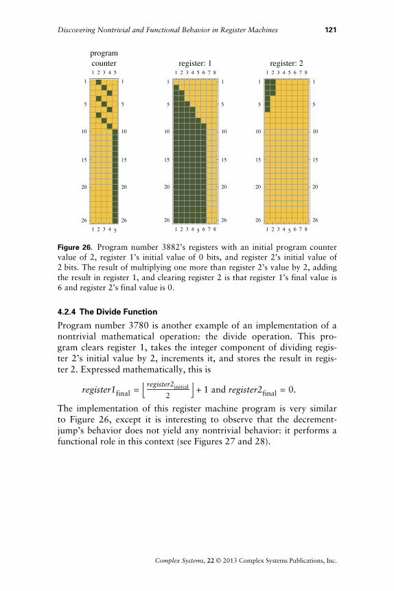
4.2.4 The Divide Function
Program number 3780 is another example of an implementation of anontrivial mathematical operation: the divide operation. This pro-gram clears register 1, takes the integer component of dividing regis-ter 2’s initial value by 2, increments it, and stores the result in regis-ter!2. Expressed mathematically, this is
register1final = f register2initial
2v + 1 and register2final = 0.
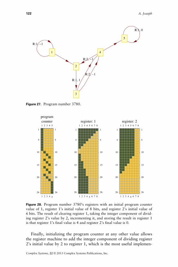
The implementation of this register machine program is very similarto Figure 26, except it is interesting to observe that the decrement-jump’s behavior does not yield any nontrivial behavior: it performs afunctional role in this context (see Figures 27 and 28).
Discovering Nontrivial and Functional Behavior in Register Machines 121
Complex Systems, 22 © 2013 Complex Systems Publications, Inc.
R:1, -1
R:1, 1
R:2, -1
R:2, -1
R:1, 0
1
2
3
4
5
Figure 27. Program number 3780.
1 2 3 4 5
1
5
10
15
20
26
1 2 3 4 51
5
10
15
20
26
programcounter
1 2 3 4 5 6 7 8
1
5
10
15
20
26
1 2 3 4 5 6 7 81
5
10
15
20
26
register: 1
1 2 3 4 5 6 7 8
1
5
10
15
20
26
1 2 3 4 5 6 7 81
5
10
15
20
26
register: 2
Figure 28. Program number 3780’s registers with an initial program countervalue of 1, register 1’s initial value of 8 bits, and register 2’s initial value of6!bits. The result of clearing register 1, taking the integer component of divid-ing register 2’s value by 2, incrementing it, and storing the result in register 1is that register 1’s final value is 4 and register 2’s final value is 0.
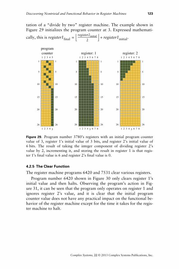
Finally, initializing the program counter at any other value allowsthe register machine to add the integer component of dividing register2’s initial value by 2 to register 1, which is the most useful implemen-
122 A. Joseph
Complex Systems, 22 © 2013 Complex Systems Publications, Inc.
y g p
tation of a “divide by two” register machine. The example shown inFigure 29 initializes the program counter at 3. Expressed mathemati-
cally, this is register1final = f register2initial
2v + register1initial.
1 2 3 4 5
1
5
10
15
20
26
1 2 3 4 51
5
10
15
20
26
programcounter
1 2 3 4 5 6 7 8
1
5
10
15
20
26
1 2 3 4 5 6 7 81
5
10
15
20
26
register: 1
1 2 3 4 5 6 7 8
1
5
10
15
20
26
1 2 3 4 5 6 7 81
5
10
15
20
26
register: 2
Figure 29. Program number 3780’s registers with an initial program countervalue of 3, register 1’s initial value of 3 bits, and register 2’s initial value of6!bits. The result of taking the integer component of dividing register 2’svalue by 2, incrementing it, and storing the result in register 1 is that regis-ter!1’s final value is 6 and register 2’s final value is 0.
4.2.5 The Clear Function
The register machine programs 6420 and 7531 clear various registers.Program number 6420 shown in Figure 30 only clears register 1’s
initial value and then halts. Observing the program’s action in Fig-ure!31, it can be seen that the program only operates on register 1 andignores register 2’s value, and it is clear that the initial programcounter value does not have any practical impact on the functional be-havior of the register machine except for the time it takes for the regis-ter machine to halt.
Discovering Nontrivial and Functional Behavior in Register Machines 123
Complex Systems, 22 © 2013 Complex Systems Publications, Inc.

R:1, -1
R:1, -1
R:1, -1
R:1, -1
R:1, 01 2 3 4 5
Figure 30. Program number 6420.
1 2 3 4 5
1
5
10
15
20
26
1 2 3 4 51
5
10
15
20
26
programcounter
1 2 3 4 5 6 7 8
1
5
10
15
20
26
1 2 3 4 5 6 7 81
5
10
15
20
26
register: 1
1 2 3 4 5 6 7 8
1
5
10
15
20
26
1 2 3 4 5 6 7 81
5
10
15
20
26
register: 2
Figure 31. Program number 6420’s registers with an initial program countervalue of 4, register 1’s initial value of 3 bits, and register 2’s initial value of5!bits. The result of clearing register 1 is that register 1’s final value is 0 andregister 2’s final value is 5.
Program number 7531, shown in Figures 32 and 33, has a similarbehavior to program number 6420, except it clears register 2 insteadof register 1.
R:2, -1
R:2, -1
R:2, -1
R:2, -1
R:1, 01 2 3 4 5
Figure 32. Functional behavior example: program number 7531’s program.
124 A. Joseph
Complex Systems, 22 © 2013 Complex Systems Publications, Inc.

1 2 3 4 5
1
5
10
15
20
26
1 2 3 4 51
5
10
15
20
26
programcounter
1 2 3 4 5 6 7 8
1
5
10
15
20
26
1 2 3 4 5 6 7 81
5
10
15
20
26
register: 1
1 2 3 4 5 6 7 8
1
5
10
15
20
26
1 2 3 4 5 6 7 81
5
10
15
20
26
register: 2
Figure 33. Program number 7531’s registers with an initial program countervalue of 4, register 1’s initial value of 3 bits, and register 2’s initial value of5!bits. The result of clearing register 2 is that register 1’s final value is 3 andregister 2’s final value is 5.
5. Conclusions
5.1 Investigation ResultsFrom the results obtained, it is clear that register machines with afour-instruction, two-register configuration exhibit nontrivial andfunctional behavior. The set of register machine programs yieldedmultiple examples of nontrivial behavior, so further investigation forexamples of nontrivial behavior with more complicated register ma-chine configurations is warranted.
The examples of functional behavior exhibited by the simple four-instruction, two-register configuration is similar to the behavior typi-cally seen in embedded platforms, where a “working” register is usedas both an input and an output for a function. For example, an addi-tion operation would add the contents of a register to the working reg-ister, storing the result in the working register. The contents of theworking register would then be copied to another register for futureuse or used immediately for a subsequent operation. This supports thenotion that register machines are good theoretical models of modernmicrocontroller and microprocessor technology.
Discovering Nontrivial and Functional Behavior in Register Machines 125
Complex Systems, 22 © 2013 Complex Systems Publications, Inc.
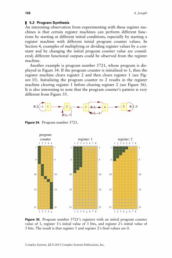
5.2 Program SynthesisAn interesting observation from experimenting with these register ma-chines is that certain register machines can perform different func-tions by starting at different initial conditions, especially by starting aregister machine with different initial program counter values. InSection 4, examples of multiplying or dividing register values by a con-stant and by changing the initial program counter value are consid-ered; different functional outputs could be observed from the registermachine.
Another example is program number 5721, whose program is dis-played in Figure 34. If the program counter is initialized to 1, then theregister machine clears register 2 and then clears register 1 (see Fig-ure!35). Initializing the program counter to 2 results in the registermachine clearing register 1 before clearing register 2 (see Figure 36).It is also interesting to note that the program counter’s pattern is verydifferent from Figure 35.
R:2, -1
R:1, -1
R:2, -1
R:2, -1
R:1, 01 2 3 4 5
Figure 34. Program number 5721.
1 2 3 4 5
1
5
10
15
21
1 2 3 4 5
1
5
10
15
21
programcounter
1 2 3 4 5 6 7 8
1
5
10
15
21
1 2 3 4 5 6 7 8
1
5
10
15
21
register: 1
1 2 3 4 5 6 7 8
1
5
10
15
21
1 2 3 4 5 6 7 8
1
5
10
15
21
register: 2
Figure 35. Program number 5721’s registers with an initial program countervalue of 1, register 1’s initial value of 3 bits, and register 2’s initial value of5!bits. The result is that register 1 and register 2’s final values are 0.
126 A. Joseph
Complex Systems, 22 © 2013 Complex Systems Publications, Inc.

1 2 3 4 5
1
5
10
15
21
1 2 3 4 5
1
5
10
15
21
programcounter
1 2 3 4 5 6 7 8
1
5
10
15
21
1 2 3 4 5 6 7 8
1
5
10
15
21
register: 1
1 2 3 4 5 6 7 8
1
5
10
15
21
1 2 3 4 5 6 7 8
1
5
10
15
21
register: 2
Figure 36. Program number 5721’s registers with an initial program countervalue of 2, register 1’s initial value of 3 bits, and register 2’s initial value of5!bits. The result is that register 1 and register 2’s final values are 0.
Finally, initializing the program counter to 3 results in the registermachine clearing only register 2 and then halting without altering thevalue of register 1 (see Figure 37).
1 2 3 4 5
1
5
10
15
21
1 2 3 4 5
1
5
10
15
21
programcounter
1 2 3 4 5 6 7 8
1
5
10
15
21
1 2 3 4 5 6 7 8
1
5
10
15
21
register: 1
1 2 3 4 5 6 7 8
1
5
10
15
21
1 2 3 4 5 6 7 8
1
5
10
15
21
register: 2
Figure 37. Program number 5721’s registers with an initial program countervalue of 3, register 1’s initial value of 3 bits, and register 2’s initial value of5!bits. The result is that register 1’s final value is 3 and register 2’s final valueis 0.
Discovering Nontrivial and Functional Behavior in Register Machines 127
Complex Systems, 22 © 2013 Complex Systems Publications, Inc.
While this behavior has simple implications, this does suggest thatthe creation can be optimized for low-level logic devices or otherBoolean logic using logic gates, such as complex programmable logicdevices (CPLDs) and field programmable gate arrays (FPGAs) by cre-ating these “super-programs,” which exhibit unique behavior by us-ing different initial conditions. Theoretically, this is advantageous asthis would offer lower overall usage of hardware components such aslogic gates, potentially reducing the cost or size of an end product.
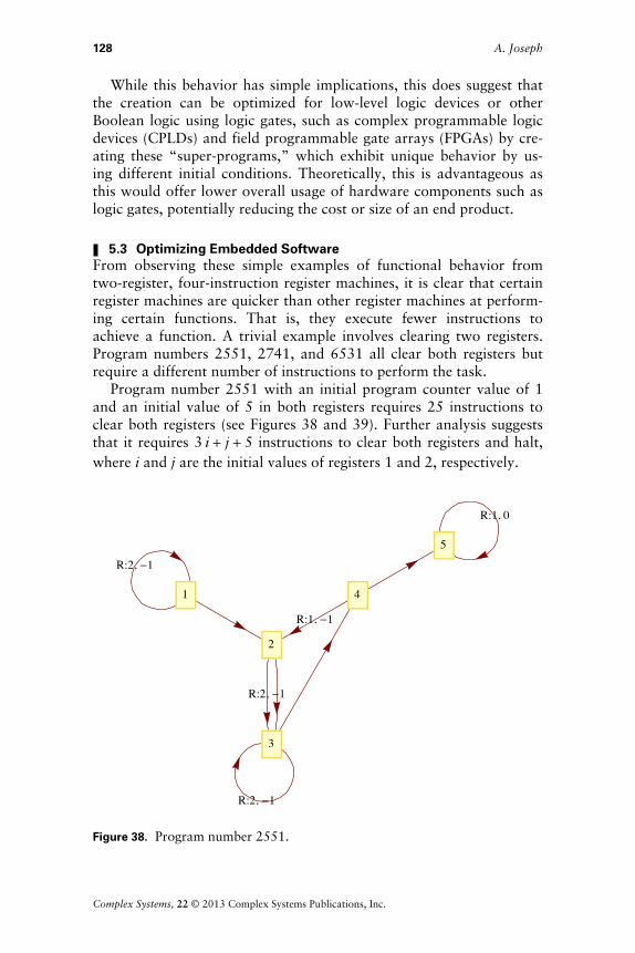
5.3 Optimizing Embedded SoftwareFrom observing these simple examples of functional behavior fromtwo-register, four-instruction register machines, it is clear that certainregister machines are quicker than other register machines at perform-ing certain functions. That is, they execute fewer instructions toachieve a function. A trivial example involves clearing two registers.Program numbers 2551, 2741, and 6531 all clear both registers butrequire a different number of instructions to perform the task.
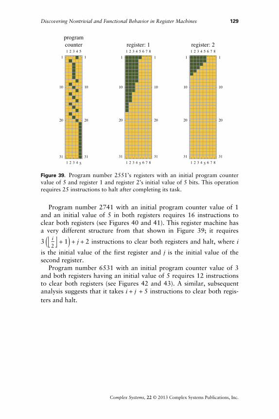
Program number 2551 with an initial program counter value of 1and an initial value of 5 in both registers requires 25 instructions toclear both registers (see Figures 38 and 39). Further analysis suggeststhat it requires 3 i + j + 5 instructions to clear both registers and halt,where i and j are the initial values of registers 1 and 2, respectively.
R:2, -1
R:2, -1
R:2, -1
R:1, -1
R:1, 0
1
2
3
4
5
Figure 38. Program number 2551.
128 A. Joseph
Complex Systems, 22 © 2013 Complex Systems Publications, Inc.
1 2 3 4 5
1
10
20
31
1 2 3 4 51
10
20
31
programcounter
1 2 3 4 5 6 7 8
1
10
20
31
1 2 3 4 5 6 7 81
10
20
31
register: 1
1 2 3 4 5 6 7 8
1
10
20
31
1 2 3 4 5 6 7 81
10
20
31
register: 2
Figure 39. Program number 2551’s registers with an initial program countervalue of 5 and register 1 and register 2’s initial value of 5 bits. This operationrequires 25 instructions to halt after completing its task.
Program number 2741 with an initial program counter value of 1and an initial value of 5 in both registers requires 16 instructions toclear both registers (see Figures 40 and 41). This register machine hasa very different structure from that shown in Figure 39; it requires
3 Jf i
2v + 1N + j + 2 instructions to clear both registers and halt, where i
is the initial value of the first register and j is the initial value of thesecond register.
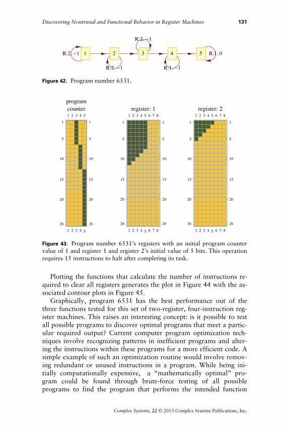
Program number 6531 with an initial program counter value of 3and both registers having an initial value of 5 requires 12 instructionsto clear both registers (see Figures 42 and 43). A similar, subsequentanalysis suggests that it takes i + j + 5 instructions to clear both regis-ters and halt.
Discovering Nontrivial and Functional Behavior in Register Machines 129
Complex Systems, 22 © 2013 Complex Systems Publications, Inc.

R:2, -1
R:1, -1
R:2, -1
R:1, -1
R:1, 0
1
2
3
4
5
Figure 40. Program number 2741’s program.
1 2 3 4 5
1
10
20
31
1 2 3 4 51
10
20
31
programcounter
1 2 3 4 5 6 7 8
1
10
20
31
1 2 3 4 5 6 7 81
10
20
31
register: 1
1 2 3 4 5 6 7 8
1
10
20
31
1 2 3 4 5 6 7 81
10
20
31
register: 2
Figure 41. Program number 2741’s registers with an initial program countervalue of 1 and register 1 and register 2’s initial value of 5 bits. This operationrequires 16 instructions to halt after completing its task.
130 A. Joseph
Complex Systems, 22 © 2013 Complex Systems Publications, Inc.
R:2, -1
R:2, -1
R:2, -1
R:1, -1
R:1, 01 2 3 4 5
Figure 42. Program number 6531.
1 2 3 4 5
1
5
10
15
20
26
1 2 3 4 51
5
10
15
20
26
programcounter
1 2 3 4 5 6 7 8
1
5
10
15
20
26
1 2 3 4 5 6 7 81
5
10
15
20
26
register: 1
1 2 3 4 5 6 7 8
1
5
10
15
20
26
1 2 3 4 5 6 7 81
5
10
15
20
26
register: 2
Figure 43. Program number 6531’s registers with an initial program countervalue of 1 and register 1 and register 2’s initial value of 5 bits. This operationrequires 15 instructions to halt after completing its task.
Plotting the functions that calculate the number of instructions re-quired to clear all registers generates the plot in Figure 44 with the as-sociated contour plots in Figure 45.
Graphically, program 6531 has the best performance out of thethree functions tested for this set of two-register, four-instruction reg-ister machines. This raises an interesting concept: is it possible to testall possible programs to discover optimal programs that meet a partic-ular required output? Current computer program optimization tech-niques involve recognizing patterns in inefficient programs and alter-ing the instructions within these programs for a more efficient code. Asimple example of such an optimization routine would involve remov-ing redundant or unused instructions in a program. While being ini-tially computationally expensive, a “mathematically optimal” pro-gram could be found through brute-force testing of all possibleprograms to find the program that performs the intended function
Discovering Nontrivial and Functional Behavior in Register Machines 131
Complex Systems, 22 © 2013 Complex Systems Publications, Inc.

p g p g p while being optimized for a particular goal, such as finding the fastestor smallest program.
Figure 44. Three-dimensional plot of functions that calculate time to halt:program 2552 halts in 3 i + j + 5 instructions, program 2742 halts in
3 Jf i
2v + 1N + j + 2 instructions, and program 6531 halts in i + j + 5
instructions.
Figure 45. Contour plots of functions that calculate time to halt: program
2552 halts in 3 i + j + 5 instructions, program 2742 halts in 3 Jf i
2v + 1N + j + 2
instructions, and program 6531 halts in i + j + 5 instructions.
After discussions with Wolfram and Todd Rowland, the authorwas introduced to the concept of superoptimizing as coined by Alexia(Henry) Massalin: a process if “given an instruction set, the superopti-mizer finds the shortest program to compute a function” [4]. Unfortu-
132 A. Joseph
Complex Systems, 22 © 2013 Complex Systems Publications, Inc.
p g p
nately, Massalin’s superoptimizer originally required several hours toexplore programs of 12 instructions on a 16MHz computer [4]. How-ever, given the rapid performance, reliability, and capacity improve-ments in modern hardware, could superoptimization be used as a de-sign tool for firmware and embedded software developers to optimizeperformance or resource-intensive routines against a set of goals—optimizing for performance, energy use, or other metrics besides codesize? These results could be adapted into a set of existing “rules” foroptimization—peephole optimization—similar to the concept pro-posed by Sorav Bansal and Alex Aiken [5] where a database of out-puts is created and desired outputs are searched for with the addi-tional capability of optimizing for other design goals.
6. Future Research Directions
6.1 Register MachinesFuture research into register machines would involve exploring moresophisticated register machines with more instructions and registersand larger register widths. From studying these simple register ma-chines, examples of nontrivial behavior can be observed. In addition,the following basic mathematical and logic functions were identified:
† add the contents of a register to another register,
† subtract the contents of a register from another register,
† multiply the contents of a register by a constant value,
† divide the contents of a register by a constant value, and
† clear a register’s contents.
Given the computational simplicity of the register machine, if amore precise definition of nontrivial behavior is used it would be pos-sible to automatically discover further examples of nontrivial behav-ior by testing all possible register machine configurations with variousinitial conditions. Joost Joosten et al. conduct a highly detailed analy-sis of the complexity associated with Turing machines, in particularby considering another measure of descriptional complexity, wherethey define a Turing machine as being nontrivial (in this paper’s con-text) “if its shortest description [where the description is the Turingmachine and its input] cannot be much more shorter than the lengthof the string [the Turing machine’s output] itself” [6]. More sophisti-cated pattern recognition techniques could assist in detecting exam-ples of randomness beyond the frequency analysis conducted. In addi-tion, this paper assumed that the data stored in a register was storedin a 1:1 ratio; that is, a value of 5 was represented by 5 bits. Other
Discovering Nontrivial and Functional Behavior in Register Machines 133
Complex Systems, 22 © 2013 Complex Systems Publications, Inc.

p y data representation systems could also be investigated, such as binary,octal, or binary-coded decimals, to discover further examples of func-tional behavior in a similar way to the representations considered forTuring machines in [6].
6.2 Practical SuperoptimizationFrom the results in Section 5.3, the following set of circumstancesnow make superoptimization a viable and deterministic method of op-timizing embedded software programs:
† cheaper, more accessible, and powerful computing infrastructure includ-ing grid- and cloud-computing systems using modern service modelslike platform as a service (PaaS) through providers such as Google AppEngine and Windows Azure;
† improved support for embedded software development such as simula-tors, emulators, and profilers; and
† a need to be able to optimize software programs running on off-the-shelf hardware to meet a variety of non-functional requirements.
Therefore, future superoptimizer studies could study applicationsof superoptimizing in other programming languages or investigate dif-ferent scenario types relevant to contemporary software engineering,such as reducing energy consumption or heat generated. In addition,complex programmable logic devices (CPLDs) often use proprietaryprogramming languages such as the very high speed integrated circuit(VHSIC) hardware description language (VHDL) as defined in IEEEStandard 1076-2008, which would be amenable to superoptimizationgiven the large industry adoption of the language, availability of emu-lation tools, and current access to high-performance computing infras-tructure. Potential superoptimization scenarios could include optimiz-ing a program for reduced execution time, smaller code size, fewerlogic gates used, reducing heat emissions, or reducing energyconsumption.
Acknowledgments
This paper is based on work the author did during the New Kind ofScience Summer School 2007. The author is very grateful for the assis-tance and guidance provided by Dr. Stephen Wolfram, Dr. Todd Row-land, Dr. Eric Rowland, and the other administrators, tutors,Wolfram Research, Inc. personnel, and fellow students at the summerschool.
134 A. Joseph
Complex Systems, 22 © 2013 Complex Systems Publications, Inc.

The author would also like to thank his friend Mr. Deon Ponciniand supervisors who provided valuable feedback as well as family,friends, and colleagues who provided advice, feedback, and support.
Wolfram Mathematica, Apple MacBook, Google App Engine, andWindows Azure are trademarks of their respective owners.
Appendix
A. Register Machine Functions
The following algorithms are implemented in Mathematica and areused in the “Register Machine” Demonstration available on theWolfram Demonstrations site [3].
A.1 Register Machine EnumerationThe following algorithm is used to decode an enumeration, rangingfrom zero to the total number of register machine programs asdefined.
convertEnumerationToState@value_,numberOfInstructions_, numberOfRegisters_D := Module@8currentState, nextState, registerNumber, increment<,
currentState = Quotient@value - 1,HHnumberOfInstructions + 1L*numberOfRegistersLD + 1;
nextState = If@Mod@value - 1, HnumberOfInstructions + 1L*numberOfRegistersD >= numberOfInstructions*
numberOfRegisters, Mod@Quotient@value - 1,HnumberOfInstructions + 1L*numberOfRegistersD,HnumberOfInstructions + 1L*numberOfRegistersD + 2,
Quotient@Mod@value - 1, HnumberOfInstructions + 1L*numberOfRegistersD, numberOfRegistersD + 1D;
registerNumber = Mod@value - 1, numberOfRegistersD + 1;
increment = If@Mod@value - 1,HnumberOfInstructions + 1L*numberOfRegistersD >=numberOfInstructions*numberOfRegisters, 1, -1D;
currentState -> 8nextState, registerNumber, increment<D;A.2 Total Register Machine Program Algorithm
Definition 1. The total number of register machine programs can be cal-culated by the function HrHi + 1LLi, where i is the number of instruc-tions and r is the number of registers.
Consider an individual instruction: if there are i instructions in aregister, then there must be i+1 possible instructions including thehalted state.
Discovering Nontrivial and Functional Behavior in Register Machines 135
Complex Systems, 22 © 2013 Complex Systems Publications, Inc.
Consider that any register machine instruction has:
† a current instruction itself,
† the next instruction to be executed, and
† the register that is being manipulated.
Then there are: 1 possible current instruction, i +1 possible next in-structions (considering the halted instruction as a possible instruc-tion), and r possible registers. Therefore there are r(i+1) possibleinstructions.
Now select i instructions with replacement, which suggests thereare Hr Hi + 1LLi possible programs to select from.
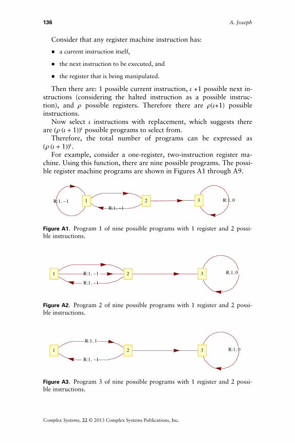
Therefore, the total number of programs can be expressed asHr Hi + 1LLi.For example, consider a one-register, two-instruction register ma-
chine. Using this function, there are nine possible programs. The possi-ble register machine programs are shown in Figures A1 through A9.
R:1, -1R:1, -1
R:1, 01 2 3
Figure A1. Program 1 of nine possible programs with 1 register and 2 possi-ble instructions.
R:1, -1
R:1, -1
R:1, 01 2 3
Figure A2. Program 2 of nine possible programs with 1 register and 2 possi-ble instructions.
R:1, 1
R:1, -1
R:1, 01 2 3
Figure A3. Program 3 of nine possible programs with 1 register and 2 possi-ble instructions.
136 A. Joseph
Complex Systems, 22 © 2013 Complex Systems Publications, Inc.

R:1, -1
R:1, -1
R:1, 01 2 3
Figure A4. Program 4 of nine possible programs with 1 register and 2 possi-ble instructions.
R:1, -1
R:1, -1
R:1, 01 2 3
Figure A5. Program 5 of nine possible programs with 1 register and 2 possi-ble instructions.
R:1, 1
R:1, -1
R:1, 01 2 3
Figure A6. Program 6 of nine possible programs with 1 register and 2 possi-ble instructions.
R:1, -1 R:1, 1 R:1, 01 2 3
Figure A7. Program 7 of nine possible programs with 1 register and 2 possi-ble instructions.
Discovering Nontrivial and Functional Behavior in Register Machines 137
Complex Systems, 22 © 2013 Complex Systems Publications, Inc.
R:1, -1
R:1, 1 R:1, 01 2 3
Figure A8. Program 8 of nine possible programs with 1 register and 2 possi-ble instructions.
R:1, 1 R:1, 1 R:1, 01 2 3
Figure A9. Program 9 of nine possible programs with 1 register and 2 possi-ble instructions.
B. Raw p-Values of Frequency Analysis of Randomness in Register Values
The p-values and the respective counts for the distribution fit test ofregister 1’s value against the discrete uniform distribution are shownat the left of Table B1.
The p-values and the respective counts for the distribution fit testof register 2’s value against the discrete uniform distribution areshown at the right of Table B1.
138 A. Joseph
Complex Systems, 22 © 2013 Complex Systems Publications, Inc.

p-Value Count
0.00485213 338 328
0.0178312 4348
0.0556449 4960
0.144973 5396
0.310289 6262
0.317311 176 640
0.449329 161 520
0.539749 8446
0.563703 192 800
0.564718 156 860
0.572407 162 454
0.606531 151 138
0.702359 117 994
0.74768 167 496
0.753004 143 906
0.765857 10 938
0.808363 65 380
0.855695 92 488
0.873007 73 172
0.884549 50 114
0.914033 12 792
0.924313 59 818
0.939992 54 978
0.952577 24 124
0.963099 40 644
0.97244 20 522
0.97314 17 220
0.97365 31 916
0.974754 15 346
1. 192 000
p-Value Count
0.0000310387 338 328
0.000454396 4348
0.00477391 4960
0.0344301 5396
0.161964 6262
0.472102 8446
0.563703 192 800
0.778801 176 640
0.818731 161 520
0.835225 10 938
0.881015 151 138
0.930627 156 860
0.945023 162 454
0.955375 167 496
0.973735 143 906
0.97874 117 994
0.984748 92 488
0.988102 12 792
0.992123 73 172
0.993373 65 380
0.996969 59 818
0.997839 54 978
0.998178 50 114
0.99896 17 220
0.999319 40 644
0.999923 31 916
0.999934 24 124
0.99999 15 346
1. 20 522
Table B1.
Discovering Nontrivial and Functional Behavior in Register Machines 139
Complex Systems, 22 © 2013 Complex Systems Publications, Inc.

C. Arithmetic Function Program List
Sections C.1 through C.4 list the programs that for at least one initialprogram counter value performed a particular arithmetic function.These program numbers correspond to the enumeration defined in Ap-pendix A and can be used in the Wolfram Demonstrations Project [3].
C.1 Addition ProgramsThe following 189 register machines add register 2’s contents to regis-ter 1, expressed mathematically as
register1final = register1initial + register2initial :
119, 319, 519, 719, 1119, 1319, 1381, 1382, 1383, 1384, 1385, 1386,1387, 1388, 1389, 1390, 1519, 1619, 1689, 1719, 1790, 1799, 1849,1860, 3119, 3319, 3381, 3382, 3383, 3384, 3385, 3386, 3387, 3388,3389, 3390, 3519, 3619, 3719, 3819, 3919, 5119, 5319, 5381, 5382,5383, 5384, 5385, 5386, 5387, 5388, 5389, 5390, 5519, 5619, 5719,5801, 5802, 5803, 5804, 5805, 5806, 5807, 5808, 5809, 5810, 5811,5812, 5813, 5814, 5815, 5816, 5817, 5818, 5819, 5820, 5821, 5822,5823, 5824, 5825, 5826, 5827, 5828, 5829, 5830, 5831, 5832, 5833,5834, 5835, 5836, 5837, 5838, 5839, 5840, 5841, 5842, 5843, 5844,5845, 5846, 5847, 5848, 5849, 5850, 5851, 5852, 5853, 5854, 5855,5856, 5857, 5858, 5859, 5860, 5861, 5862, 5863, 5864, 5865, 5866,5867, 5868, 5869, 5870, 5871, 5872, 5873, 5874, 5875, 5876, 5877,5878, 5879, 5880, 5881, 5882, 5883, 5884, 5885, 5886, 5887, 5888,5889, 5890, 5891, 5892, 5893, 5894, 5895, 5896, 5897, 5898, 5899,5900, 5919, 7119, 7319, 7381, 7382, 7383, 7384, 7385, 7386, 7387,7388, 7389, 7390, 7519, 7619, 7719, 7919, 9119, 9319, 9381, 9382,9383, 9384, 9385, 9386, 9387, 9388, 9389, 9390, 9519, 9619, 9719,and 9919.
The following 189 register machines add register 1’s contents to regis-ter 2, expressed mathematically as
register2final = register1initial + register2initial :
10, 210, 291, 292, 293, 294, 295, 296, 297, 298, 299, 300, 410, 610,690, 699, 710, 800, 949, 960, 1010, 1210, 1410, 1610, 2010, 2210,2291, 2292, 2293, 2294, 2295, 2296, 2297, 2298, 2299, 2300, 2410,2610, 2710, 2810, 2910, 4010, 4210, 4291, 4292, 4293, 4294, 4295,4296, 4297, 4298, 4299, 4300, 4410, 4610, 4710, 4810, 4901, 4902,4903, 4904, 4905, 4906, 4907, 4908, 4909, 4910, 4911, 4912, 4913,4914, 4915, 4916, 4917, 4918, 4919, 4920, 4921, 4922, 4923, 4924,4925, 4926, 4927, 4928, 4929, 4930, 4931, 4932, 4933, 4934, 4935,4936, 4937, 4938, 4939, 4940, 4941, 4942, 4943, 4944, 4945, 4946,4947, 4948, 4949, 4950, 4951, 4952, 4953, 4954, 4955, 4956, 4957,4958, 4959, 4960, 4961, 4962, 4963, 4964, 4965, 4966, 4967, 4968,4969, 4970, 4971, 4972, 4973, 4974, 4975, 4976, 4977, 4978, 4979,4980, 4981, 4982, 4983, 4984, 4985, 4986, 4987, 4988, 4989, 4990,
140 A. Joseph
Complex Systems, 22 © 2013 Complex Systems Publications, Inc.
4991, 4992, 4993, 4994, 4995, 4996, 4997, 4998, 4999, 5000, 6010,6210, 6291, 6292, 6293, 6294, 6295, 6296, 6297, 6298, 6299, 6300,6410, 6610, 6710, 6810, 8010, 8210, 8291, 8292, 8293, 8294, 8295,8296, 8297, 8298, 8299, 8300, 8410, 8610, 8710, and 8810.
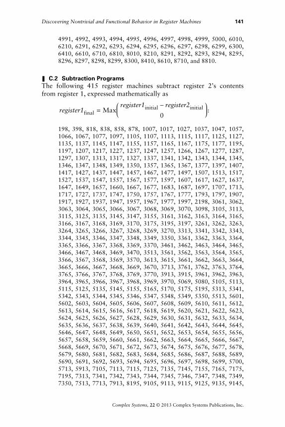
C.2 Subtraction ProgramsThe following 415 register machines subtract register 2’s contentsfrom register 1, expressed mathematically as
register1final = Maxregister1initial - register2initial
0:
198, 398, 818, 838, 858, 878, 1007, 1017, 1027, 1037, 1047, 1057,1066, 1067, 1077, 1097, 1105, 1107, 1113, 1115, 1117, 1125, 1127,1135, 1137, 1145, 1147, 1155, 1157, 1165, 1167, 1175, 1177, 1195,1197, 1207, 1217, 1227, 1237, 1247, 1257, 1266, 1267, 1277, 1287,1297, 1307, 1313, 1317, 1327, 1337, 1341, 1342, 1343, 1344, 1345,1346, 1347, 1348, 1349, 1350, 1357, 1365, 1367, 1377, 1397, 1407,1417, 1427, 1437, 1447, 1457, 1467, 1477, 1497, 1507, 1513, 1517,1527, 1537, 1547, 1557, 1567, 1577, 1597, 1607, 1617, 1627, 1637,1647, 1649, 1657, 1660, 1667, 1677, 1683, 1687, 1697, 1707, 1713,1717, 1727, 1737, 1747, 1750, 1757, 1767, 1777, 1793, 1797, 1907,1917, 1927, 1937, 1947, 1957, 1967, 1977, 1997, 2198, 3061, 3062,3063, 3064, 3065, 3066, 3067, 3068, 3069, 3070, 3098, 3105, 3113,3115, 3125, 3135, 3145, 3147, 3155, 3161, 3162, 3163, 3164, 3165,3166, 3167, 3168, 3169, 3170, 3175, 3195, 3197, 3261, 3262, 3263,3264, 3265, 3266, 3267, 3268, 3269, 3270, 3313, 3341, 3342, 3343,3344, 3345, 3346, 3347, 3348, 3349, 3350, 3361, 3362, 3363, 3364,3365, 3366, 3367, 3368, 3369, 3370, 3461, 3462, 3463, 3464, 3465,3466, 3467, 3468, 3469, 3470, 3513, 3561, 3562, 3563, 3564, 3565,3566, 3567, 3568, 3569, 3570, 3613, 3615, 3661, 3662, 3663, 3664,3665, 3666, 3667, 3668, 3669, 3670, 3713, 3761, 3762, 3763, 3764,3765, 3766, 3767, 3768, 3769, 3770, 3913, 3915, 3961, 3962, 3963,3964, 3965, 3966, 3967, 3968, 3969, 3970, 5069, 5080, 5105, 5113,5115, 5125, 5135, 5145, 5155, 5165, 5170, 5175, 5195, 5313, 5341,5342, 5343, 5344, 5345, 5346, 5347, 5348, 5349, 5350, 5513, 5601,5602, 5603, 5604, 5605, 5606, 5607, 5608, 5609, 5610, 5611, 5612,5613, 5614, 5615, 5616, 5617, 5618, 5619, 5620, 5621, 5622, 5623,5624, 5625, 5626, 5627, 5628, 5629, 5630, 5631, 5632, 5633, 5634,5635, 5636, 5637, 5638, 5639, 5640, 5641, 5642, 5643, 5644, 5645,5646, 5647, 5648, 5649, 5650, 5651, 5652, 5653, 5654, 5655, 5656,5657, 5658, 5659, 5660, 5661, 5662, 5663, 5664, 5665, 5666, 5667,5668, 5669, 5670, 5671, 5672, 5673, 5674, 5675, 5676, 5677, 5678,5679, 5680, 5681, 5682, 5683, 5684, 5685, 5686, 5687, 5688, 5689,5690, 5691, 5692, 5693, 5694, 5695, 5696, 5697, 5698, 5699, 5700,5713, 5913, 7105, 7113, 7115, 7125, 7135, 7145, 7155, 7165, 7175,7195, 7313, 7341, 7342, 7343, 7344, 7345, 7346, 7347, 7348, 7349,7350, 7513, 7713, 7913, 8195, 9105, 9113, 9115, 9125, 9135, 9145,
Discovering Nontrivial and Functional Behavior in Register Machines 141
Complex Systems, 22 © 2013 Complex Systems Publications, Inc.
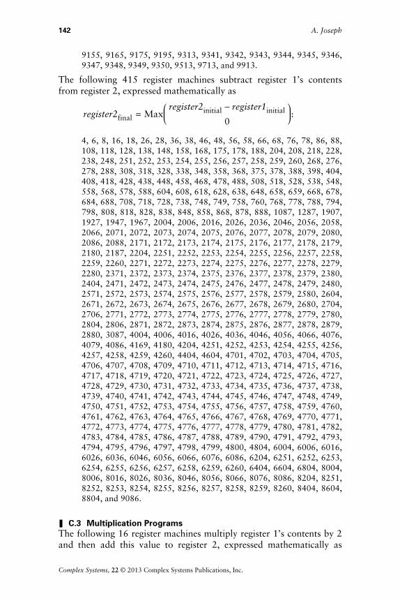
9155, 9165, 9175, 9195, 9313, 9341, 9342, 9343, 9344, 9345, 9346,9347, 9348, 9349, 9350, 9513, 9713, and 9913.
The following 415 register machines subtract register 1’s contentsfrom register 2, expressed mathematically as
register2final = Maxregister2initial - register1initial
0:
4, 6, 8, 16, 18, 26, 28, 36, 38, 46, 48, 56, 58, 66, 68, 76, 78, 86, 88,108, 118, 128, 138, 148, 158, 168, 175, 178, 188, 204, 208, 218, 228,238, 248, 251, 252, 253, 254, 255, 256, 257, 258, 259, 260, 268, 276,278, 288, 308, 318, 328, 338, 348, 358, 368, 375, 378, 388, 398, 404,408, 418, 428, 438, 448, 458, 468, 478, 488, 508, 518, 528, 538, 548,558, 568, 578, 588, 604, 608, 618, 628, 638, 648, 658, 659, 668, 678,684, 688, 708, 718, 728, 738, 748, 749, 758, 760, 768, 778, 788, 794,798, 808, 818, 828, 838, 848, 858, 868, 878, 888, 1087, 1287, 1907,1927, 1947, 1967, 2004, 2006, 2016, 2026, 2036, 2046, 2056, 2058,2066, 2071, 2072, 2073, 2074, 2075, 2076, 2077, 2078, 2079, 2080,2086, 2088, 2171, 2172, 2173, 2174, 2175, 2176, 2177, 2178, 2179,2180, 2187, 2204, 2251, 2252, 2253, 2254, 2255, 2256, 2257, 2258,2259, 2260, 2271, 2272, 2273, 2274, 2275, 2276, 2277, 2278, 2279,2280, 2371, 2372, 2373, 2374, 2375, 2376, 2377, 2378, 2379, 2380,2404, 2471, 2472, 2473, 2474, 2475, 2476, 2477, 2478, 2479, 2480,2571, 2572, 2573, 2574, 2575, 2576, 2577, 2578, 2579, 2580, 2604,2671, 2672, 2673, 2674, 2675, 2676, 2677, 2678, 2679, 2680, 2704,2706, 2771, 2772, 2773, 2774, 2775, 2776, 2777, 2778, 2779, 2780,2804, 2806, 2871, 2872, 2873, 2874, 2875, 2876, 2877, 2878, 2879,2880, 3087, 4004, 4006, 4016, 4026, 4036, 4046, 4056, 4066, 4076,4079, 4086, 4169, 4180, 4204, 4251, 4252, 4253, 4254, 4255, 4256,4257, 4258, 4259, 4260, 4404, 4604, 4701, 4702, 4703, 4704, 4705,4706, 4707, 4708, 4709, 4710, 4711, 4712, 4713, 4714, 4715, 4716,4717, 4718, 4719, 4720, 4721, 4722, 4723, 4724, 4725, 4726, 4727,4728, 4729, 4730, 4731, 4732, 4733, 4734, 4735, 4736, 4737, 4738,4739, 4740, 4741, 4742, 4743, 4744, 4745, 4746, 4747, 4748, 4749,4750, 4751, 4752, 4753, 4754, 4755, 4756, 4757, 4758, 4759, 4760,4761, 4762, 4763, 4764, 4765, 4766, 4767, 4768, 4769, 4770, 4771,4772, 4773, 4774, 4775, 4776, 4777, 4778, 4779, 4780, 4781, 4782,4783, 4784, 4785, 4786, 4787, 4788, 4789, 4790, 4791, 4792, 4793,4794, 4795, 4796, 4797, 4798, 4799, 4800, 4804, 6004, 6006, 6016,6026, 6036, 6046, 6056, 6066, 6076, 6086, 6204, 6251, 6252, 6253,6254, 6255, 6256, 6257, 6258, 6259, 6260, 6404, 6604, 6804, 8004,8006, 8016, 8026, 8036, 8046, 8056, 8066, 8076, 8086, 8204, 8251,8252, 8253, 8254, 8255, 8256, 8257, 8258, 8259, 8260, 8404, 8604,8804, and 9086.
C.3 Multiplication ProgramsThe following 16 register machines multiply register 1’s contents by 2and then add this value to register 2, expressed mathematically as
142 A. Joseph
Complex Systems, 22 © 2013 Complex Systems Publications, Inc.

g p y
register1final = register1initial + 2 * register2initial:
1189, 2189, 3189, 3881, 3882, 3883, 3884, 3885, 3886, 3887, 3888,3890, 5189, 7189, and 9189.
The following 16 register machines multiply register 1’s contentsby 2 and then add this value to register 2, expressed mathematicallyas register2final = register2initial + 2 * register1initial:
100, 2100, 2991, 2992, 2993, 2994, 2995, 2996, 2997, 2998, 2999,3000, 3100, 4100, 6100, and 8100.
C.4 Division ProgramsRegister machines 3780 and 3851 take the integral part of dividingregister 2’s value by 2, incrementing the value, and storing the resultin register 1, otherwise expressed mathematically as
register1final = f register2initial
2v + 1.
Register machines 2692 and 2942 similarly take the integral part of di-viding register 1’s value by 2, incrementing the value, and storing theresult in register 2, otherwise expressed mathematically as
register2final = f register1initial
2v + 1.
Much like the other arithmetic register machines mentioned in Sec-tion 4.2, the following 22 register machines take the integral part ofdividing register 2’s value by 2 and adding the result to register 1, ex-pressed mathematically as
register1final = register1initial + f register2initial
2v:
1079, 1159, 1179, 1379, 1579, 1679, 1779, 3159, 3780, 3782, 3783,3784, 3785, 3786, 3787, 3788, 3789, 3790, 5159, 5184, 7159, and9159.
The following 22 register machines take the integral part of divid-ing register 1’s value by 2 and adding the result to register 2, ex-pressed mathematically as
register2final = register2initial + f register1initial
2v:
50, 70, 170, 270, 470, 670, 770, 2050, 2691, 2692, 2693, 2694, 2695,2696, 2697, 2698, 2699, 2700, 4050, 4093, 6050, and 8050.
Discovering Nontrivial and Functional Behavior in Register Machines 143
Complex Systems, 22 © 2013 Complex Systems Publications, Inc.

D. Other Register Machine Examples
D.1 Complex Register MachinesThe register machine outputs of program 386 (Figure D1) in Fig-ures!D2 and D3 show how register machines can be observed to ei-ther halt or run indefinitely after register 1’s contents is cleared.
R:1, -1
R:1, 1 R:1, -1
R:2, -1
R:1, 012 43 5
Figure D1. Program number 386.
1 2 3 4 5
1
5
10
15
20
26
1 2 3 4 51
5
10
15
20
26
programcounter
1 2 3 4 5 6 7 8
1
5
10
15
20
26
1 2 3 4 5 6 7 81
5
10
15
20
26
register: 1
1 2 3 4 5 6 7 8
1
5
10
15
20
26
1 2 3 4 5 6 7 81
5
10
15
20
26
register: 2
Figure D2. Program number 386’s registers with an initial program countervalue of 2, register 1’s initial value of 3 bits, and register 2’s initial value of4!bits.
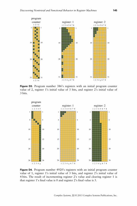
D.2 Functional Register MachinesD.2.1 The Addition Operation
The register machine shown in Figures D4 and D5 increments the con-tents of the second register before halting, a specific implementationof the addition function.
144 A. Joseph
Complex Systems, 22 © 2013 Complex Systems Publications, Inc.
1 2 3 4
1
10
20
31
1 2 3 41
10
20
31
programcounter
1 2 3 4 5 6 7 8
1
10
20
31
1 2 3 4 5 6 7 81
10
20
31
register: 1
1 2 3 4 5 6 7 8
1
10
20
31
1 2 3 4 5 6 7 81
10
20
31
register: 2
Figure D3. Program number 386’s registers with an initial program countervalue of 2, register 1’s initial value of 3 bits, and register 2’s initial value of3!bits.
1 2 3 4 5
1
5
10
15
20
26
1 2 3 4 51
5
10
15
20
26
programcounter
1 2 3 4 5 6 7 8
1
5
10
15
20
26
1 2 3 4 5 6 7 81
5
10
15
20
26
register: 1
1 2 3 4 5 6 7 8
1
5
10
15
20
26
1 2 3 4 5 6 7 81
5
10
15
20
26
register: 2
Figure D4. Program number 4920’s registers with an initial program countervalue of 1, register 1’s initial value of 3 bits, and register 2’s initial value of4!bits. The result of incrementing register 2’s value and clearing register 1 isthat register 1’s final value is 0 and register 2’s final value is 5.
Discovering Nontrivial and Functional Behavior in Register Machines 145
Complex Systems, 22 © 2013 Complex Systems Publications, Inc.
R:1, -1
R:1, -1
R:2, 1
R:1, -1R:1, 01 2 3 4 5
Figure D5. Program number 4920.
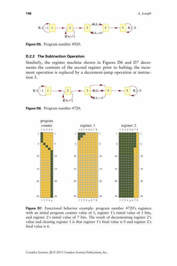
D.2.2 The Subtraction Operation
Similarly, the register machine shown in Figures D6 and D7 decre-ments the contents of the second register prior to halting; the incre-ment operation is replaced by a decrement-jump operation at instruc-tion 3.
R:1, -1
R:1, -1
R:2, -1
R:1, -1
R:1, 01 2 3 4 5
Figure D6. Program number 4720.
1 2 3 4 5
1
5
10
15
20
26
1 2 3 4 51
5
10
15
20
26
programcounter
1 2 3 4 5 6 7 8
1
5
10
15
20
26
1 2 3 4 5 6 7 81
5
10
15
20
26
register: 1
1 2 3 4 5 6 7 8
1
5
10
15
20
26
1 2 3 4 5 6 7 81
5
10
15
20
26
register: 2
Figure D7. Functional behavior example: program number 4720’s registerswith an initial program counter value of 1, register 1’s initial value of 3 bits,and register 2’s initial value of 7 bits. The result of decrementing register 2’svalue and clearing register 1 is that register 1’s final value is 0 and register 2’sfinal value is 6.
146 A. Joseph
Complex Systems, 22 © 2013 Complex Systems Publications, Inc.
D.2.3 The Multiplication Operation
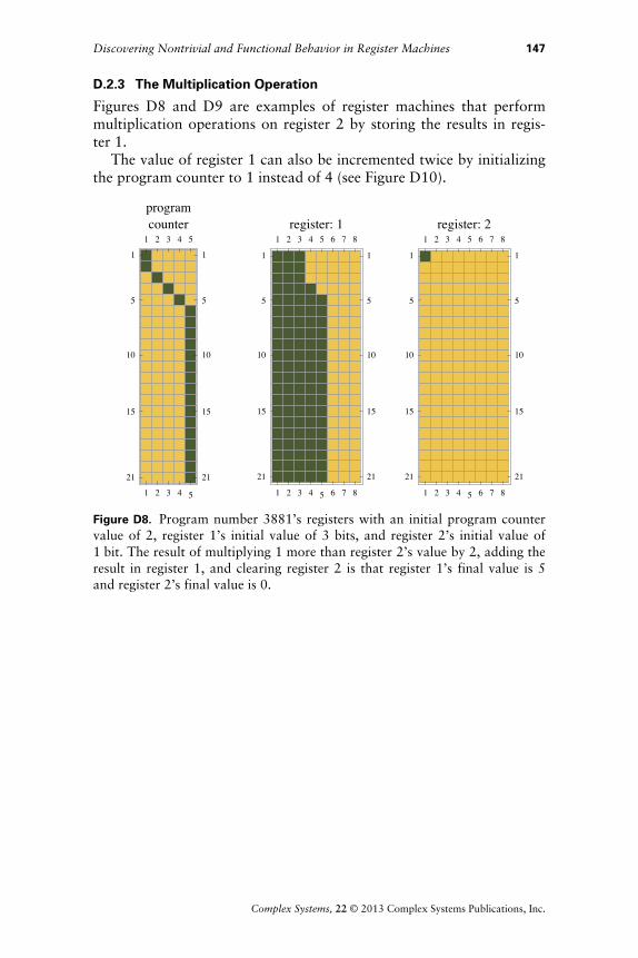
Figures D8 and D9 are examples of register machines that performmultiplication operations on register 2 by storing the results in regis-ter 1.
The value of register 1 can also be incremented twice by initializingthe program counter to 1 instead of 4 (see Figure D10).
1 2 3 4 5
1
5
10
15
21
1 2 3 4 5
1
5
10
15
21
programcounter
1 2 3 4 5 6 7 8
1
5
10
15
21
1 2 3 4 5 6 7 8
1
5
10
15
21
register: 1
1 2 3 4 5 6 7 8
1
5
10
15
21
1 2 3 4 5 6 7 8
1
5
10
15
21
register: 2
Figure D8. Program number 3881’s registers with an initial program countervalue of 2, register 1’s initial value of 3 bits, and register 2’s initial value of1!bit. The result of multiplying 1 more than register 2’s value by 2, adding theresult in register 1, and clearing register 2 is that register 1’s final value is 5and register 2’s final value is 0.
Discovering Nontrivial and Functional Behavior in Register Machines 147
Complex Systems, 22 © 2013 Complex Systems Publications, Inc.

1 2 3 4 5
1
5
10
15
21
1 2 3 4 5
1
5
10
15
21
programcounter
1 2 3 4 5 6 7 8
1
5
10
15
21
1 2 3 4 5 6 7 8
1
5
10
15
21
register: 1
1 2 3 4 5 6 7 8
1
5
10
15
21
1 2 3 4 5 6 7 8
1
5
10
15
21
register: 2
Figure D9. Program number 3881’s registers with an initial program countervalue of 4, register 1’s initial value of 3 bits, and register 2’s initial value of2!bits. The result of multiplying register 2’s value by 2, adding the result toregister 1, and clearing register 2 is that register 1’s final value is 7 and regis-ter 2’s final value is 0.
1 2 3 4 5
1
5
10
15
21
1 2 3 4 5
1
5
10
15
21
programcounter
1 2 3 4 5 6 7 8
1
5
10
15
21
1 2 3 4 5 6 7 8
1
5
10
15
21
register: 1
1 2 3 4 5 6 7 8
1
5
10
15
21
1 2 3 4 5 6 7 8
1
5
10
15
21
register: 2
Figure D10. Program number 3881’s registers with an initial program countervalue of 1, register 1’s initial value of 4 bits, and register 2’s initial value of8!bits. The result of incrementing register 1’s value twice, adding the result toregister 1, and clearing register 2 is that register 1’s final value is 6 and regis-ter 2’s final value is 0.
148 A. Joseph
Complex Systems, 22 © 2013 Complex Systems Publications, Inc.
References
[1] S. Wolfram, A New Kind of Science, Champaign IL: Wolfram Media,Inc, 2002.
[2] P. Chapman. “Minsky Register Machine.” (Jan 13, 2003)http://www.igblan.free-online.co.uk/igblan/ca/minsky.html.
[3] A. Joseph. “Register Machines” from the Wolfram Demonstrations Pro-ject—A Wolfram Web Resource.http://demonstrations.wolfram.com/RegisterMachines.
[4] H. Massalin, “Superoptimizer: A Look at the Smallest Program” in Pro-ceedings of the Second International Conference on Architectural Sup-port for Programming Languages and Operating Systems (ASPLOS87),Berkeley, CA (R. Katz, ed.), Los Alamitos, CA: IEEE Computer SocietyPress, 1987 pp. 122–126. doi:10.1145/36177.36194.
[5] S. Bansal and A. Aiken, “Automatic Generation of Peephole Superopti-mizers,” ACM SIGPLAN Notices, 41(11), 2006 pp. 394–403.doi:10.1145/1168918.1168906.
[6] J. J. Joosten, F. Soler-Toscano, and H. Zenil, “Program-Size versus TimeComplexity Slowdown and Speed-up Phenomena in the Micro-cosmosof Small Turing Machines,” International Journal of UnconventionalComputing, 7(5), 2011 pp. 353–387.
Discovering Nontrivial and Functional Behavior in Register Machines 149
Complex Systems, 22 © 2013 Complex Systems Publications, Inc.