discovery builders, inc. 8527.000.000 supplemental...
TRANSCRIPT

Discovery Builders, Inc. 8527.000.000
Proposed Delta Gateway Extension West and Pad 12 October 8, 2008
SUPPLEMENTAL GEOTECHNICAL RECOMMENDATIONS Page 2
Proposed Development
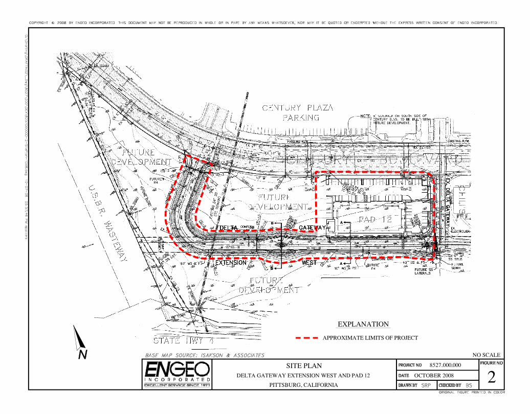
According to the preliminary plans, the proposed extension includes new pavement areas,
including curb-and-gutter, sidewalks, and access easement with solid concrete abutments for the
existing PG&E towers, vegetated and earth swales, and underground utilities. In addition,
proposed development for Pad 12 is likely to be commercial/retail with an expected moderate
structure load. Foundations are likely to be either shallow footings or a structural slab.
Site History
A geotechnical report was prepared by Converse Consultants in 1986 for the Baker Property
(Reference 1) which later became Century Plaza, covering the proposed area for the current
extension and Pad 12. Century Plaza nearby comprises mostly of retail and commercial
development. According to a subsequent grading report by Converse Consultants (Reference 2)
done after mass grading, the portion of the site where the proposed extension is planned was
graded so that the upper 3 feet comprise of low-to-moderately expansive soils.
Our current study has incorporated findings of the Converse Consultants report, as deemed
appropriate, in connection with the planned development. This supplemental report is intended
to supersede previous recommendations provided in the Converse Consultants report.
CONCLUSION AND SUPPLEMENTAL RECOMMENDATIONS
Based on our review of previous site work and this supplemental study, it is our opinion that the
site is suitable for the proposed development provided the recommendations contained herein are
incorporated into the project design and implemented during construction.
Site Grading
All grading and site development plans should be coordinated with the Geotechnical Engineer.
ENGEO should be notified at least 48 hours prior to grading in order to coordinate our schedule
with the grading contractor. Grading operations should meet the requirements of the attached
"Guide Contract Specifications" and must be observed and tested by ENGEO's field
representatives.
Selection of Materials. With the exception of organically contaminated near-surface materials,
the site soils are suitable for use as engineered fill. If import material is being considered, it must
meet the requirements contained in Section 2.02B, Part I of the attached Guide Contract
Specifications. A sample of the proposed import material should be submitted to the
Geotechnical Engineer for evaluation by laboratory testing prior to site delivery.

Discovery Builders, Inc. 8527.000.000
Proposed Delta Gateway Extension West and Pad 12 October 8, 2008
SUPPLEMENTAL GEOTECHNICAL RECOMMENDATIONS Page 3
Placement of Fill. Areas to receive fill should be scarified to a depth of 12 inches in-place, moisture
conditioned in-place, and recompacted in-place to provide adequate bonding with the initial lift of
fill. All fills should be placed in thin lifts. The lift thickness should not exceed 8 inches or the depth
of penetration of the compaction equipment used, whichever is less.
Monitoring and Testing. Based on the Converse Consultants reports, mass grading for the
Century Plaza development took place in 1987, and the project area for proposed Delta Gateway
Extension West and Pad 12 was part the mass grading. Therefore, minor grading associated with
the proposed street and building pad and surrounding site improvements is anticipated. The
following general specifications for compaction should be used:
Test Procedures: ASTM D-1557.
Required Moisture Content: Not less than 4 percent above optimum
moisture content.
Minimum Relative Compaction: Between 85 to 90 percent.
The Geotechnical Engineer’s qualified representative should be present during all phases of
grading operations to observe site preparation, grading operations, and subdrain placement.
Foundation Design
Provided below are foundation recommendations along with design criteria for various systems
that may be considered appropriate for Pad 12 including shallow footing combined with
slabs-on-grade, or post-tensioned structural mat.
Continuous and Isolated Footings. The proposed buildings may be supported by continuous and
isolated footing combined with floor slabs-on-grade. The footings should be designed according
to the following design criteria:
Maximum Allowable Bearing Pressure: 2,000 psf for dead plus live loads for
continuous and column footings. This value
can be increased by 1/3 to include seismic or
wind loads.
Minimum Depth of Footing Embedment: At least 18 inches below lowest pad grade.
Discovery Builders, Inc. 8527.000.000
Proposed Delta Gateway Extension West and Pad 12 October 8, 2008
SUPPLEMENTAL GEOTECHNICAL RECOMMENDATIONS Page 4
Resistance to short duration (earthquake-induced) lateral loads may be provided by frictional
resistance between the foundation concrete and the subgrade soils and by passive earth pressure
acting against the side of the foundation. A coefficient of friction of 0.35 can be used between
concrete and the subgrade. A uniform pressure of 1,000 psf can be used to evaluate the passive
resistance that can be developed on the foundation elements for transient loads. The upper 1 foot
of soil should be excluded from passive pressure computations unless it is confined by pavement
or a concrete slab. A combination of both friction and passive pressure may be used if one of the
values is reduced by 50 percent.
Footing trenches should be cleared of all loose materials, and soils exposed in footing
excavations should not be allowed to desiccate prior to placing concrete. The Geotechnical
Engineer or his/her field representative should observe the footing trenches prior to concrete
placement.
Floor Slabs-on-Grade. Concrete slabs should be at least 5 inches thick. However, the slab
thickness and reinforcing should be designed by the Structural Engineer based on the intended
use and loading of the slab. Some cracking of the slabs-on-grade should be anticipated at the site
as a result of concrete shrinkage. Frequent control joints should be provided to control the
cracking.
If the building is constructed with concrete slabs-on-grade, water vapor from beneath the slab
will migrate through the slab and into the building. This water vapor can be reduced but not
stopped. Vapor transmission can negatively affect floor coverings and lead to increased moisture
within a building. When water vapor migrating through the slab would be undesirable, we
recommend the following to reduce, but not stop, water vapor transmission upward through the
slab-on-grade.
1. Install a vapor retarder membrane directly beneath the slab. Seal the vapor retarder at all
seams and pipe penetrations. Vapor retarders shall conform to Class A vapor retarder in
accordance with ASTM E 1745-97 “Standard Specification for Plastic Water Vapor
Retarders used in Contact with Soil or Granular Fill under Concrete Slabs.”
2. Concrete shall have a concrete water-cement ratio of no more than 0.5.
3. Provide inspection and testing during concrete placement to check that the proper concrete
and water-cement ratio are used.
4. Consider adequate moist curing of slabs.
The Structural Engineer should be consulted as to the use of a layer of clean sand (less than
5 percent passing the U.S. Standard No. 200 Sieve) placed on top of the vapor retarder
membrane to assist in concrete curing. Protect foundation subgrade soils from seepage by
providing impermeable plugs within utility trenches.

Discovery Builders, Inc. 8527.000.000
Proposed Delta Gateway Extension West and Pad 12 October 8, 2008
SUPPLEMENTAL GEOTECHNICAL RECOMMENDATIONS Page 5
Cracking of the slabs-on-grade may be anticipated as a result of concrete shrinkage. To control
location of cracks, frequent control joints should be provided. The slab designer should specify
appropriate spacing and location of control joints for cracking; concrete expansion joints should
be filled with elastomeric sealant. Sealant should be examined regularly for possible openings
that may develop. If additional measures are desired to further reduce cracking, the designer
should consider added steel reinforcement, use of “fibermesh” - steel fibers entrained in concrete
mix, or a concrete mix intended to reduce shrinkage.
Structural/Post-Tensioned Mat Systems. The proposed structure can also be supported on
structural mat foundation systems. If this system is employed the structural mats should be stiff
to resist differential movements across mat and be compatible with the superstructure; the
Structural Engineer and Architect should be consulted on this matter.
Mats should be designed for a uniform bearing pressure of 1,000 pounds per square foot (psf) for
dead-plus-live load. This value may be increased to 1,800 psf under individual columns or walls
to accommodate stress concentrations at those locations. These values can be increased by 1/3
for seismic loading. A minimum mat thickness of 10 inches is recommended. The perimeter
should be thickened by 2 inches, and the minimum soil backfill height against the slab at the
perimeter should be 6 inches.
Post-tensioned structural mat should be designed according to the method recommended in
“Design and Construction of Post-Tensioned Slabs-On-Ground, Third Edition” (Post-Tensioning
Institute, 2004). Based upon the anticipated soil treatment at the site, we recommend using the
following soil criteria for design of the post-tensioned mat foundations:
Center Lift Condition:
Edge Moisture Variation Distance, em = 7.5 feet
Differential Soil Movement, ym = 0.6 inches
Edge Lift Condition:
Edge Moisture Variation Distance, em = 4.5 feet
Differential Soil Movement, ym = 1.5 inches
Updated CBC 2007 Seismic Criteria
An earthquake of moderate-to-high magnitude generated within the San Francisco Bay Region,
similar to those that have occurred in the past, could cause considerable ground shaking at the
site. To mitigate the shaking effects, all structures should be designed using sound engineering
judgment and the latest California Building Code (CBC) requirements. Using the USGS website
Seismic Design Values for Buildings, Ground Motion Parameter Calculator, we provide the
following 2007 CBC seismic parameters using the ASCE 7.5 and 2006 IBC calculation modules.

Discovery Builders, Inc. 8527.000.000
Proposed Delta Gateway Extension West and Pad 12 October 8, 2008
SUPPLEMENTAL GEOTECHNICAL RECOMMENDATIONS Page 6
2007 CBC Seismic Parameters
ITEM DESIGN VALUE
Site Class D
0.2 second Spectral response Acceleration, Ss 1.50
1.0 second Spectral response Acceleration, S1 0.55
Site Coefficient, Fa 1.0
Site Coefficient, FV 1.5
Maximum considered earthquake spectral response
accelerations for short periods, SMS 1.50
Maximum considered earthquake spectral response
accelerations for 1-second periods, SM1 0.83
Design spectral response acceleration at short
periods, SDS 1.00
Design spectral response acceleration at 1-second
periods, SD1 0.55
Long-period Transition Period, TL 8 seconds
Seismic design provisions of current building codes generally prescribe minimum lateral forces
applied statically to the structure, combined with the gravity forces of dead and live loads. The
code-prescribed lateral forces are generally substantially smaller than the expected peak forces
that would be associated with a major earthquake. Therefore, structures should be able to
(1) resist minor earthquakes without damage, (2) resist moderate earthquakes without structural
damage but with some nonstructural damage, and (3) resist major earthquakes without collapse
but with some structural as well as nonstructural damage. Conformance to the current building
code recommendations does not constitute a guarantee that significant structural damage would
not occur in the event of a maximum magnitude earthquake; however, it is reasonable to expect
that a well-designed and well-constructed structure will not collapse or cause loss of life in a
major earthquake (SEAOC, 1996).
Exterior Concrete Slab-on-Grade and Related Flatwork.
This section provides guidelines for exterior concrete slabs such as sidewalks, walkways and other
concrete flatwork. Where slab-on-grade construction is anticipated, care must be exercised in
attaining a near-saturation condition of the subgrade soil before concrete placement. Slabs-on-grade
should be designed specifically for their intended use and loading requirements by the
Structural Engineer. As mentioned previously, the site soils have a low-to-moderate expansion
potential; therefore, cracking of conventional slabs should be expected in the future. To reduce and
control cracking, slabs-on-grade should be reinforced with steel rebar and provided with frequent
control joints. The actual reinforcement should be designed by the Structural Engineer and should,
as a minimum, consist of No. 3 bars spaced 16 inches on center each way. In our experience, welded
wire mesh is not sufficient to control slab cracking.
Discovery Builders, Inc. 8527.000.000
Proposed Delta Gateway Extension West and Pad 12 October 8, 2008
SUPPLEMENTAL GEOTECHNICAL RECOMMENDATIONS Page 7
Slabs-on-grade should have a minimum thickness of 5 inches. A 4-inch-thick layer of clean
crushed rock or gravel (Section 2.04, Part I of Guide Contract Specifications) should be placed
under slabs. Exterior slabs should be constructed with thickened edges extending at least
6 inches into compacted soil to minimize water infiltration. Slabs should slope away from the
buildings at a slope of at least 2 percent to prevent water from flowing toward the building.
Frequent control joints should be provided to control the cracking.
Corrosivity Considerations
ENGEO collected a representative sample of the near-surface soils during our field
reconnaissance to determine the potential for sulfate attack on foundation concrete and to
provide recommended concrete design parameters in accordance with the guidelines presented in
Chapter 19 of the Uniform Building Code (1997). We transported the sample with an
appropriate Chain of Custody to our San Ramon laboratory for concentrations of water-soluble
sulfate (SO4) in accordance with Caltrans Test Method 417. As reported in the attached
analytical results, the sample tested had a 33 mg/kg water-soluble sulfate (SO4) concentration
level.
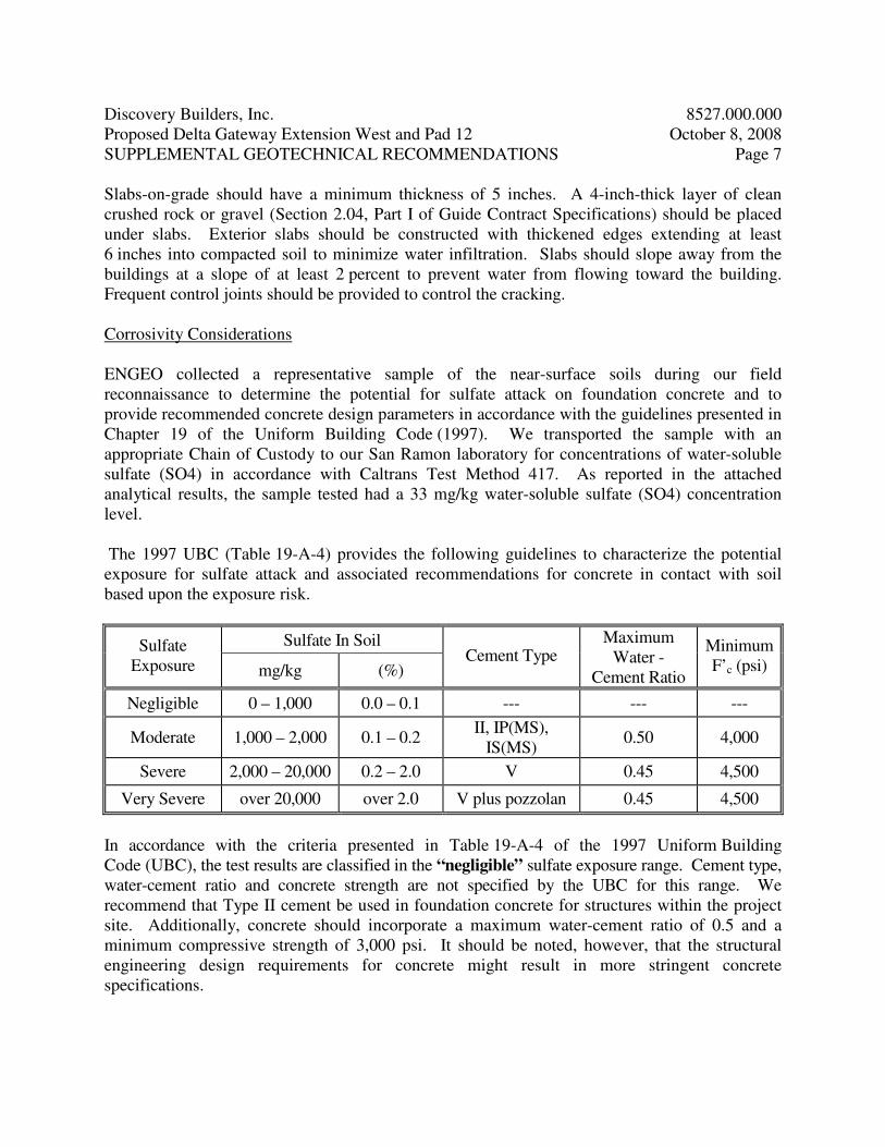
The 1997 UBC (Table 19-A-4) provides the following guidelines to characterize the potential
exposure for sulfate attack and associated recommendations for concrete in contact with soil
based upon the exposure risk.
Sulfate In Soil Sulfate
Exposure mg/kg (%) Cement Type
Maximum
Water -
Cement Ratio
Minimum
F’c (psi)
Negligible 0 – 1,000 0.0 – 0.1 --- --- ---
Moderate 1,000 – 2,000 0.1 – 0.2 II, IP(MS),
IS(MS) 0.50 4,000
Severe 2,000 – 20,000 0.2 – 2.0 V 0.45 4,500
Very Severe over 20,000 over 2.0 V plus pozzolan 0.45 4,500
In accordance with the criteria presented in Table 19-A-4 of the 1997 Uniform Building
Code (UBC), the test results are classified in the “negligible” sulfate exposure range. Cement type,
water-cement ratio and concrete strength are not specified by the UBC for this range. We
recommend that Type II cement be used in foundation concrete for structures within the project
site. Additionally, concrete should incorporate a maximum water-cement ratio of 0.5 and a
minimum compressive strength of 3,000 psi. It should be noted, however, that the structural
engineering design requirements for concrete might result in more stringent concrete
specifications.

Discovery Builders, Inc. 8527.000.000
Proposed Delta Gateway Extension West and Pad 12 October 8, 2008
SUPPLEMENTAL GEOTECHNICAL RECOMMENDATIONS Page 8
Preliminary Pavement Design
An R-value test performed on the fill material by Converse Consultants resulted in an R-value
of 21. For our design we have assumed a minimum R-value of 10 to account for variability. The
following pavement sections are recommended using Procedure 608 of the Caltrans Highway
Design Manual (including the asphalt factor of safety), presented in the table below. The Civil
Engineer should determine the appropriate traffic indices based on the estimated traffic loads and
frequencies.
Traffic Index AC (inches) AB (inches)
5 3 8
6 3 ½ 12
7 4 15
AC is asphaltic concrete
AB is aggregate base Class 2 Material with minimum R = 78
Pavement construction and all materials should conform to the specifications and requirements
of the Standard Specifications by the State of California Department of Transportation, City of
Pittsburg requirements, and the following minimum requirements.
• Pavement subgrades (street and sidewalk) should be scarified in-place to a depth of 12 inches
below finished subgrade elevation, moisture conditioned to at least 3 percentage points above
optimum, and compacted to at least 95 percent relative compaction and in accordance with
City requirements. Alternate placement specifications may be warranted for
chemically-treated materials.
• Subgrade soils should be in a stable, non-pumping condition at the time aggregate baserock
materials are placed and compacted. Proof-rolling with a heavy wheel-loaded piece of
construction equipment should be implemented. Yielding materials should be appropriately
mitigated, with suitable mitigation measures developed in coordination with the client,
contractor and consultant (i.e. subexcavating pumping materials, lime treatment, geogrid
fabric, etc.).
• Adequate provisions must be made such that the subgrade soils and aggregate base materials
are not allowed to become saturated.
• Aggregate base materials should meet current Caltrans specifications for Class 2 aggregate
base and should be compacted to at least 95 percent of maximum dry density at a moisture
content of at least optimum (ASTM Test Methods).
Discovery Builders, Inc. 8527.000.000
Proposed Delta Gateway Extension West and Pad 12 October 8, 2008
SUPPLEMENTAL GEOTECHNICAL RECOMMENDATIONS Page 9
• All concrete curbs separating pavement and irrigated landscaped areas should extend into the
subgrade and below the bottom of adjacent aggregate base materials. An undercurb drain
could also be considered to help collect and transport subsurface seepage.
Surface Drainage
It is very important that the lot be positively graded at all times to provide for rapid removal of
surface water. Ponding of water under floors or seepage toward foundation systems at any time
during or after construction must be prevented. Finished grades should provide a slope gradient to
drain positively away from structures. Care should be exercised to ensure that landscape mounds
will not interfere with these requirements. Storm water from roof downspouts should be conveyed
in closed drain systems to a drainage facility.
Utilities
It is recommended that utility trench backfilling be done under the observation of a
Geotechnical Engineer. Pipe zone backfill (i.e. material beneath and immediately surrounding
the pipe) may consist of a well-graded import or native material less than ¾ inch in maximum
dimension compacted in accordance with recommendations provided above for engineered fill.
Trench zone backfill (i.e. material placed between the pipe zone backfill and the ground surface)
may consist of native soil compacted in accordance with recommendations for engineered fill.
Where import material is used for pipe zone backfill, we recommend it consist of
fine-to-medium grained sand or a well-graded mixture of sand and gravel and that this material
not be used within 2 feet of finish grades. In general, uniformly graded gravel should not be
used for pipe or trench zone backfill due to the potential for migration of: (1) soil into the
relatively large void spaces present in this type of material, and (2) water along trenches
backfilled with this type of material. All utility trenches entering the houses and paved areas
must be provided with an impervious seal consisting of native materials or concrete where the
trenches pass under the building perimeter or curb lines. The impervious plug should extend at
least 4 feet to either side of the crossing. This is to prevent surface-water percolation into the
sands under foundations and pavements where such water would remain trapped in a perched
condition, allowing clays to develop their full expansion potential. All trench backfill should be
compacted using approved techniques to a minimum of 90 percent relative compaction and
4 percent above optimum in native site soils.
Care should be exercised where utility trenches are located beside foundation areas. Utility
trenches constructed parallel to foundations should be located entirely above a plane extending
down from the lower edge of the footing at an angle of 45 degrees. Utility companies and
Landscape Architects should be made aware of this information.

Discovery Builders, Inc. 8527.000.000
Proposed Delta Gateway Extension West and Pad 12 October 8, 2008
SUPPLEMENTAL GEOTECHNICAL RECOMMENDATIONS Page 10
Compaction of native trench backfill by jetting should not be allowed at the site. If there appears
to be a conflict between the City of Pittsburg or other agency requirements and the
recommendations contained in this report, this should be brought to the Owner’s attention for
resolution prior to submitting bids.
We hope this provides the information that you require at this time. If you have any questions,
please contact us.
Very truly yours,
ENGEO Incorporated
Jesús I. Espinoza, CE Theodore P. Bayham, GE
jie/vss
Attachment: Limitations and Uniformity of Conditions
Figures 1 and 2
Guide Contract Specifications
Appendix A: Laboratory Test Results
8527.000.000
September 30, 2008
LIMITATIONS AND UNIFORMITY OF CONDITIONS
This report is issued with the understanding that it is the responsibility of the owner to transmit
the information and recommendations of this report to buyers, architects, engineers and designers
for the project so that the necessary steps can be taken by the contractors and subcontractors to
carry out such recommendations in the field. The conclusions and recommendations contained
in this report are solely professional opinions.
The professional staff of ENGEO Incorporated strives to perform its services in a proper and
professional manner with reasonable care and competence but is not infallible. There are risks of
earth movement and property damages inherent in land development. We are unable to
eliminate all risks or provide insurance; therefore, we are unable to guarantee or warrant the
results of our work.
This report is based upon field and other conditions discovered at the time of preparation of
ENGEO’s work. This document must not be subject to unauthorized reuse, that is, reuse without
written authorization of ENGEO. Such authorization is essential because it requires ENGEO to
evaluate the document’s applicability given new circumstances, not the least of which is passage
of time. If actual field or other conditions necessitate clarifications, adjustments, modifications
or other changes to ENGEO’s work, ENGEO must be engaged to prepare the necessary
clarifications, adjustments, modifications or other changes before construction activities
commence or further activity proceeds. If ENGEO’s scope of services does not include on-site
construction observation, or if other persons or entities are retained to provide such services,
ENGEO cannot be held responsible for any or all claims arising from or resulting from the
performance of such services by other persons or entities, and from any or all claims arising from
or resulting from clarifications, adjustments, modifications, discrepancies or other changes
necessary to reflect changed field or other conditions.

GUIDE CONTRACT SPECIFICATIONS
PART I - EARTHWORK
PREFACE
These specifications are intended as a guide for the earthwork performed at the subject
development project. If there is a conflict between these specifications (including the
recommendations of the geotechnical report) and agency or code requirements, it should be
brought to the attention of ENGEO and Owner prior to contract bidding.
PART 1 - GENERAL
1.01 WORK COVERED
A. Grading, excavating, filling and backfilling, including trenching and backfilling for
utilities as necessary to complete the Project as indicated on the Drawings.
B. Subsurface drainage as indicated on the Drawings.
1.02 CODES AND STANDARDS
A. Excavating, trenching, filling, backfilling, and grading work shall meet the applicable
requirements of the Uniform Building Code and the standards and ordinances of state
and local governing authorities.
1.03 SUBSURFACE SOIL CONDITIONS
A. The Owners' Geotechnical Exploration report is available for inspection by bidder or
Contractor. The Contractor shall refer to the findings and recommendations of the
Geotechnical Exploration report in planning and executing his work.
1.04 DEFINITIONS
A. Fill: All soil, rock, or soil-rock materials placed to raise the grades of the site or to
backfill excavations.
B. Backfill: All soil, rock or soil-rock material used to fill excavations and trenches.
C. On-Site Material: Soil and/or rock material which is obtained from the site.
D. Imported Material: Soil and/or rock material which is brought to the site from off-site
areas.

E. Select Material: On-site and/or imported material which is approved by ENGEO as a
specific-purpose fill.
F. Engineered Fill: Fill upon which ENGEO has made sufficient observations and tests
to confirm that the fill has been placed and compacted in accordance with
specifications and requirements.
G. Degree of Compaction or Relative Compaction: The ratio, expressed as a percentage,
of the in-place dry density of the fill and backfill material as compacted in the field to
the maximum dry density of the same material as determined by ASTM D-1557 or
California 216 compaction test method.
H. Optimum Moisture: Water content, percentage by dry weight, corresponding to the
maximum dry density as determined by ASTM D-1557.
I. ENGEO: The project geotechnical engineering consulting firm, its employees or its
designated representatives.
J. Drawings: All documents, approved for construction, which describe the Work.
1.05 OBSERVATION AND TESTING
A. All site preparation, cutting and shaping, excavating, filling, and backfilling shall be
carried out under the observation of ENGEO, employed and paid for by the Owners.
ENGEO will perform appropriate field and laboratory tests to evaluate the suitability
of fill material, the proper moisture content for compaction, and the degree of
compaction achieved. Any fill that does not meet the specification requirements shall
be removed and/or reworked until the requirements are satisfied.
B. Cutting and shaping, excavating, conditioning, filling, and compacting procedures
require approval of ENGEO as they are performed. Any work found unsatisfactory or
any work disturbed by subsequent operations before approval is granted shall be
corrected in an approved manner as recommended by ENGEO.
C. Tests for compaction will be made in accordance with test procedures outlined in
ASTM D-1557, as applicable. Field testing of soils or compacted fill shall conform
with the applicable requirements of ASTM D-2922.
D. All authorized observation and testing will be paid for by the Owners.

1.06 SITE CONDITIONS
A. Excavating, filling, backfilling, and grading work shall not be performed during
unfavorable weather conditions. When the work is interrupted by rain, excavating,
filling, backfilling, and grading work shall not be resumed until the site and soil
conditions are suitable.
B. Contractor shall take the necessary measures to prevent erosion of freshly filled,
backfilled, and graded areas until such time as permanent drainage and erosion control
measures have been installed.
PART 2 - PRODUCTS
2.01 GENERAL
A. Contractor shall furnish all materials, tools, equipment, facilities, and services as
required for performing the required excavating, filling, backfilling, and grading work,
and trenching and backfilling for utilities.
2.02 SOIL MATERIALS
A. Fill
1. Material to be used for engineered fill and backfill shall be free from organic
matter and other deleterious substances, and of such quality that it will compact
thoroughly without excessive voids when watered and rolled. Excavated on-site
material will be considered suitable for engineered fill and backfill if it contains no
more than 3 percent organic matter, is free of debris and other deleterious
substances and conforms to the requirements specified above. Rocks of maximum
dimension in excess of two-thirds of the lift thickness shall be removed from any
fill material to the satisfaction of ENGEO.
2. Excavated earth material which is suitable for engineered fill or backfill, as
determined by ENGEO, shall be conditioned for reuse and properly stockpiled as
required for later filling and backfilling operations. Conditioning shall consist of
spreading material in layers not to exceed 8 inches and raking free of debris and
rubble. Rocks and aggregate exceeding the allowed largest dimension, and
deleterious material shall be removed from the site and disposed off site in a legal
manner.
3. ENGEO shall be immediately notified if potential hazardous materials or suspect
soils exhibiting staining or odor are encountered. Work activities shall be
discontinued within the area of potentially hazardous materials. ENGEO
environmental personnel will conduct an assessment of the suspect hazardous
material to determine the appropriate response and mitigation. Regulatory

agencies may also be contacted to request concurrence and oversight. ENGEO
will rely on the Owner, or a designated Owner’s representative, to make
necessary notices to the appropriate regulatory agencies. The Owner may request
ENGEO’s assistance in notifying regulatory agencies, provided ENGEO receives
Owner’s written authorization to expand its scope of services.
4. ENGEO shall be notified at least 48 hours prior to the start of filling and
backfilling operations so that it may evaluate samples of the material intended for
use as fill and backfill. All materials to be used for filling and backfilling require
the approval of ENGEO.
B. Import Material: Where conditions require the importation of fill material, the
material shall be an inert, nonexpansive soil or soil-rock material free of organic matter and
meeting the following requirements unless otherwise approved by ENGEO.
Gradation (ASTM D-421): Sieve Size Percent Passing
2-inch 100
#200 15 - 70
Plasticity (ASTM D-4318): Liquid Limit Plasticity Index
< 30 < 12
Swell Potential (ASTM D-4546B): Percent Heave Swell Pressure
(at optimum moisture)
< 2 percent < 300 psf
Resistance Value (ASTM D-2844): Minimum 25
Organic Content (ASTM D-2974): Less than 2 percent
A sample of the proposed import material should be submitted to ENGEO for
evaluation prior to delivery at the site.
2.03 SAND
A. Sand for sand cushion under slabs and for bedding of pipe in utility trenches shall be a
clean and graded, washed sand, free from clay or organic material, suitable for the
intended purpose with 90 to 100 percent passing a No. 4 U.S. Standard Sieve, not more
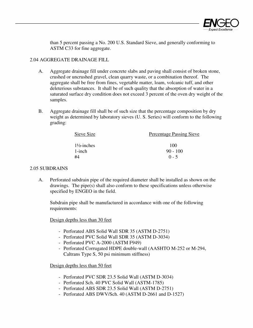
than 5 percent passing a No. 200 U.S. Standard Sieve, and generally conforming to
ASTM C33 for fine aggregate.
2.04 AGGREGATE DRAINAGE FILL
A. Aggregate drainage fill under concrete slabs and paving shall consist of broken stone,
crushed or uncrushed gravel, clean quarry waste, or a combination thereof. The
aggregate shall be free from fines, vegetable matter, loam, volcanic tuff, and other
deleterious substances. It shall be of such quality that the absorption of water in a
saturated surface dry condition does not exceed 3 percent of the oven dry weight of the
samples.
B. Aggregate drainage fill shall be of such size that the percentage composition by dry
weight as determined by laboratory sieves (U. S. Series) will conform to the following
grading:
Sieve Size Percentage Passing Sieve
1½-inches 100
1-inch 90 - 100
#4 0 - 5
2.05 SUBDRAINS
A. Perforated subdrain pipe of the required diameter shall be installed as shown on the
drawings. The pipe(s) shall also conform to these specifications unless otherwise
specified by ENGEO in the field.
Subdrain pipe shall be manufactured in accordance with one of the following
requirements:
Design depths less than 30 feet
- Perforated ABS Solid Wall SDR 35 (ASTM D-2751)
- Perforated PVC Solid Wall SDR 35 (ASTM D-3034)
- Perforated PVC A-2000 (ASTM F949)
- Perforated Corrugated HDPE double-wall (AASHTO M-252 or M-294,
Caltrans Type S, 50 psi minimum stiffness)
Design depths less than 50 feet
- Perforated PVC SDR 23.5 Solid Wall (ASTM D-3034)
- Perforated Sch. 40 PVC Solid Wall (ASTM-1785)
- Perforated ABS SDR 23.5 Solid Wall (ASTM D-2751)
- Perforated ABS DWV/Sch. 40 (ASTM D-2661 and D-1527)

- Perforated Corrugated HDPE double-wall (AASHTO M-252 or M-294,
Caltrans Type S, 70 psi minimum stiffness)
Design depths less than 70 feet
- Perforated ABS Solid Wall SDR 15.3 (ASTM D-2751)
- Perforated Sch. 80 PVC (ASTM D-1785)
- Perforated Corrugated Aluminum (ASTM B-745)
B. Permeable Material (Class 2): Class 2 permeable material for filling trenches under,
around, and over subdrains, behind building and retaining walls, and for pervious
blankets shall consist of clean, coarse sand and gravel or crushed stone, conforming to
the following grading requirements:
Sieve Size Percentage Passing Sieve
1-inch 100
¾-inch 90 - 100
⅜-inch 40 - 100
#4 25 - 40
#8 18 - 33
#30 5 - 15
#50 0 - 7
#200 0 - 3
C. Filter Fabric: All filter fabric shall meet the following Minimum Average Roll Values
unless otherwise specified by ENGEO.
Grab Strength (ASTM D-4632)..........................................180 lbs
Mass Per Unit Area (ASTM D-4751).................................6 oz/yd2
Apparent Opening Size (ASTM D-4751)...........................70-100 U.S. Std. Sieve
Flow Rate (ASTM D-4491)................................................80 gal/min/ft2
Puncture Strength (ASTM D-4833) ...................................80 lbs
D. Vapor Retarder: Vapor Retarders shall consist of PVC, LDPE or HDPE impermeable
sheeting at least 10 mils thick.
2.06 PERMEABLE MATERIAL (Class 1; Type A)
A. Class 1 permeable material to be used in conjunction with filter fabric for backfilling
of subdrain excavations shall conform to the following grading requirements:
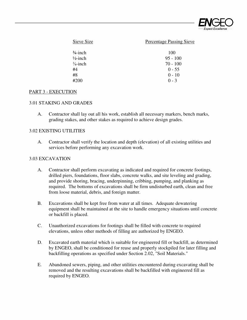
Sieve Size Percentage Passing Sieve
¾-inch 100
½-inch 95 - 100
⅜-inch 70 - 100
#4 0 - 55
#8 0 - 10
#200 0 - 3
PART 3 - EXECUTION
3.01 STAKING AND GRADES
A. Contractor shall lay out all his work, establish all necessary markers, bench marks,
grading stakes, and other stakes as required to achieve design grades.
3.02 EXISTING UTILITIES
A. Contractor shall verify the location and depth (elevation) of all existing utilities and
services before performing any excavation work.
3.03 EXCAVATION
A. Contractor shall perform excavating as indicated and required for concrete footings,
drilled piers, foundations, floor slabs, concrete walks, and site leveling and grading,
and provide shoring, bracing, underpinning, cribbing, pumping, and planking as
required. The bottoms of excavations shall be firm undisturbed earth, clean and free
from loose material, debris, and foreign matter.
B. Excavations shall be kept free from water at all times. Adequate dewatering
equipment shall be maintained at the site to handle emergency situations until concrete
or backfill is placed.
C. Unauthorized excavations for footings shall be filled with concrete to required
elevations, unless other methods of filling are authorized by ENGEO.
D. Excavated earth material which is suitable for engineered fill or backfill, as determined
by ENGEO, shall be conditioned for reuse and properly stockpiled for later filling and
backfilling operations as specified under Section 2.02, "Soil Materials."
E. Abandoned sewers, piping, and other utilities encountered during excavating shall be
removed and the resulting excavations shall be backfilled with engineered fill as
required by ENGEO.

F. Any active utility lines encountered shall be reported immediately to the Owner's
Representative and authorities involved. The Owner and proper authorities shall be
permitted free access to take the measures deemed necessary to repair, relocate, or
remove the obstruction as determined by the responsible authority or Owner's
Representative.
3.04 SUBGRADE PREPARATION
A. All brush and other rubbish, as well as trees and root systems not marked for saving,
shall be removed from the site and legally disposed of.
B. Any existing structures, foundations, underground storage tanks, or debris must be
removed from the site prior to any building, grading, or fill operations. Septic tanks,
including all drain fields and other lines, if encountered, must be totally removed. The
resulting depressions shall be properly prepared and filled to the satisfaction of
ENGEO.
C. Vegetation and organic topsoil shall be removed from the surface upon which the fill is
to be placed and either removed and legally disposed of or stockpiled for later use in
approved landscape areas. The surface shall then be scarified to a depth of at least
eight inches until the surface is free from ruts, hummocks, or other uneven features
which would tend to prevent uniform compaction by the equipment to be used.
D. After the foundation for the fill has been cleared and scarified, it shall be made
uniform and free from large clods. The proper moisture content must be obtained by
adding water or aerating. The foundation for the fill shall be compacted at the proper
moisture content to a relative compaction as specified herein.
3.05 ENGINEERED FILL
A. Select Material: Fill material shall be "Select" or "Imported Material" as previously
specified.
B. Placing and Compacting: Engineered fill shall be constructed by approved and
accepted methods. Fill material shall be spread in uniform lifts not exceeding 8 inches
in uncompacted thickness. Each layer shall be spread evenly, and thoroughly
blade-mixed to obtain uniformity of material. Fill material which does not contain
sufficient moisture as specified by ENGEO shall be sprinkled with water; if it contains
excess moisture it shall be aerated or blended with drier material to achieve the proper
water content. Select material and water shall then be thoroughly mixed before being
compacted.
C. Unless otherwise specified in the Geotechnical Exploration report, each layer of spread
select material shall be compacted to at least 90 percent relative compaction at a
moisture content of at least three percentage points above the optimum moisture

content. Minimum compaction in all keyways shall be a minimum of 95 percent with
a minimum moisture content of at least 1 percentage point above optimum.
D. Unless otherwise specified in the Geotechnical Exploration report or otherwise
required by the local authorities, the upper 6 inches of engineered fill in areas to
receive pavement shall be compacted to at least 95 percent relative compaction with a
minimum moisture content of at least 3 percentage points above optimum.
E. Testing and Observation of Fill: The work shall consist of field observation and testing
to determine that each layer has been compacted to the required density and that the
required moisture is being obtained. Any layer or portion of a layer that does not
attain the compaction required shall be reworked until the required density is obtained.
F. Compaction: Compaction shall be by sheepsfoot rollers, multiple-wheel steel or
pneumatic-tired rollers or other types of acceptable compaction equipment. Rollers
shall be of such design that they will be able to compact the fill to the specified
compaction. Rolling shall be accomplished while the fill material is within the
specified moisture content range. Rolling of each layer must be continuous so that the
required compaction may be obtained uniformly throughout each layer.
G. Fill slopes shall be constructed by overfilling the design slopes and later cutting back
the slopes to the design grades. No loose soil will be permitted on the faces of the
finished slopes.
H. Strippings and topsoil shall be stockpiled as approved by Owner, then placed in
accordance with ENGEO's recommendations to a minimum thickness of 6 inches and
a maximum thickness of 12 inches over exposed open space cut slopes which are 3:1
or flatter, and track walked to the satisfaction of ENGEO.
I. Final Prepared Subgrade: Finish blading and smoothing shall be performed as
necessary to produce the required density, with a uniform surface, smooth and true to
grade.
3.06 BACKFILLING
A. Backfill shall not be placed against footings, building walls, or other structures until
approved by ENGEO.
B. Backfill material shall be Select Material as specified for engineered fill.
C. Backfill shall be placed in 6-inch layers, leveled, rammed, and tamped in place. Each
layer shall be compacted with suitable compaction equipment to 90 percent relative
compaction at a moisture content of at least 3 percent above optimum.

3.07 TRENCHING AND BACKFILLING FOR UTILITIES
A. Trenching:
1. Trenching shall include the removal of material and obstructions, the installation
and removal of sheeting and bracing and the control of water as necessary to
provide the required utilities and services.
2. Trenches shall be excavated to the lines, grades, and dimensions indicated on the
Drawings. Maximum allowable trench width shall be the outside diameter of the
pipe plus 24 inches, inclusive of any trench bracing.
3. When the trench bottom is a soft or unstable material as determined by ENGEO, it
shall be made firm and solid by removing said unstable material to a sufficient
depth and replacing it with on-site material compacted to 90 percent minimum
relative compaction.
4. Where water is encountered in the trench, the contractor must provide materials
necessary to drain the water and stabilize the bed.
B. Backfilling:
1. Trenches must be backfilled within 2 days of excavation to minimize desiccation.
2. Bedding material shall be sand and shall not extend more than 6 inches above any
utility lines.
3. Backfill material shall be select material.
4. Trenches shall be backfilled as indicated or required and compacted with suitable
equipment to 90 percent minimum relative compaction at the required moisture
content.
3.08 SUBDRAINS
A. Trenches for subdrain pipe shall be excavated to a minimum width equal to the outside
diameter of the pipe plus at least 12 inches and to a depth of approximately 2 inches
below the grade established for the invert of the pipe, or as indicated on the Drawings.
B. The space below the pipe invert shall be filled with a layer of Class 2 permeable
material, upon which the pipe shall be laid with perforations down. Sections shall be
joined as recommended by the pipe manufacturer.

C. Rocks, bricks, broken concrete, or other hard material shall not be used to give
intermediate support to pipes. Large stones or other hard objects shall not be left in
contact with the pipes.
D. Excavations for subdrains shall be filled as required to fill voids and prevent settlement
without damaging the subdrain pipe. Alternatively, excavations for subdrains may be
filled with Class 1 permeable material (as defined in Section 2.06) wrapped in
Filter Fabric (as defined in Section 2.05).
3.09 AGGREGATE DRAINAGE FILL
A. ENGEO shall approve finished subgrades before aggregate drainage fill is installed.
B. Pipes, drains, conduits, and any other mechanical or electrical installations shall be in
place before any aggregate drainage fill is placed. Backfill at walls to elevation of
drainage fill shall be in place and compacted.
C. Aggregate drainage fill under slabs and concrete paving shall be the minimum uniform
thickness after compaction of dimensions indicated on Drawings. Where not
indicated, minimum thickness after compaction shall be 4 inches.
D. Aggregate drainage fill shall be rolled to form a well-compacted bed.
E. The finished aggregate drainage fill must be observed and approved by ENGEO before
proceeding with any subsequent construction over the compacted base or fill.
3.10 SAND CUSHION
A. A sand cushion shall be placed over the vapor retarder membrane under concrete slabs
on grade. Sand cushion shall be placed in uniform thickness as indicated on the
Drawings. Where not indicated, the thickness shall be 2 inches.
3.11 FINISH GRADING
A. All areas must be finish graded to elevations and grades indicated on the Drawings. In
areas to receive topsoil and landscape planting, finish grading shall be performed to a
uniform 6 inches below the grades and elevations indicated on the Drawings, and
brought to final grade with topsoil.
3.12 DISPOSAL OF WASTE MATERIALS
A. Excess earth materials and debris shall be removed from the site and disposed of in a
legal manner. Location of dump site and length of haul are the Contractor's
responsibility.
PART II - GEOGRID SOIL REINFORCEMENT
1. DESCRIPTION:
Work shall consist of furnishing geogrid soil reinforcement for use in construction of
reinforced soil slopes and retention systems.
2. GEOGRID MATERIAL:
2.1 The specific geogrid material shall be preapproved by ENGEO.
2.2 The geogrid shall be a regular network of integrally connected polymer tensile elements
with aperture geometry sufficient to permit significant mechanical interlock with the
surrounding soil or rock. The geogrid structure shall be dimensionally stable and able to
retain its geometry under construction stresses and shall have high resistance to damage
during construction, to ultraviolet degradation, and to all forms of chemical and
biological degradation encountered in the soil being reinforced.
2.3 The geogrids shall have an Allowable Strength (Ta) and Pullout Resistance, for the soil
type(s) indicated, as listed in Table I.
2.4 Certifications: The Contractor shall submit a manufacturer's certification that the
geogrids supplied meet the respective index criteria set when geogrid was approved by
ENGEO, measured in full accordance with all test methods and standards specified. In
case of dispute over validity of values, the Contractor will supply test data from an
ENGEO-approved laboratory to support the certified values submitted.
3. CONSTRUCTION:
3.1 Delivery, Storage, and Handling: Contractor shall check the geogrid upon delivery to
ensure that the proper material has been received. During all periods of shipment and
storage, the geogrid shall be protected from temperatures greater than 140 °F, mud, dirt,
dust, and debris. Manufacturer's recommendations in regard to protection from direct
sunlight must also be followed. At the time of installation, the geogrid will be rejected if
it has defects, tears, punctures, flaws, deterioration, or damage incurred during
manufacture, transportation, or storage. If approved by ENGEO, torn or punctured
sections may be repaired by placing a patch over the damaged area. Any geogrid
damaged during storage or installation shall be replaced by the Contractor at no
additional cost to the owner.
3.2 On-Site Representative: Geogrid material suppliers shall provide a qualified and experienced representative on site at the initiation of the project, for a minimum of three days, to assist the Contractor and ENGEO personnel at the start of construction. If there is more than one slope on a project, this criterion will apply to construction of the initial slope only. The representative shall also be available on an as-needed basis, as requested by ENGEO, during construction of the remaining slope(s).
3.3 Geogrid reinforcement may be joined with mechanical connections or overlaps as
recommended and approved by the Manufacturer. Joints shall not be placed within 6 feet of the slope face, within 4 feet below top of slope, nor horizontally or vertically adjacent to another joint.
3.4 Geogrid Placement: The geogrid reinforcement shall be installed in accordance with the
manufacturer's recommendations. The geogrid reinforcement shall be placed within the layers of the compacted soil as shown on the plans or as directed.
The geogrid reinforcement shall be placed in continuous longitudinal strips in the direction
of main reinforcement. However, if the Contractor is unable to complete a required length with a single continuous length of geogrid, a joint may be made with the Manufacturer's approval. Only one joint per length of geogrid shall be allowed. This joint shall be made for the full width of the strip by using a similar material with similar strength. Joints in geogrid reinforcement shall be pulled and held taut during fill placement.
Adjacent strips, in the case of 100 percent coverage in plan view, need not be overlapped.
The minimum horizontal coverage is 50 percent, with horizontal spacings between reinforcement no greater than 40 inches. Horizontal coverage of less than 100 percent shall not be allowed unless specifically detailed in the construction drawings.
Adjacent rolls of geogrid reinforcement shall be overlapped or mechanically connected
where exposed in a wrap around face system, as applicable. The Contractor may place only that amount of geogrid reinforcement required for
immediately pending work to prevent undue damage. After a layer of geogrid reinforcement has been placed, the next succeeding layer of soil shall be placed and compacted as appropriate. After the specified soil layer has been placed, the next geogrid reinforcement layer shall be installed. The process shall be repeated for each subsequent layer of geogrid reinforcement and soil.
Geogrid reinforcement shall be placed to lay flat and pulled tight prior to backfilling.
After a layer of geogrid reinforcement has been placed, suitable means, such as pins or small piles of soil, shall be used to hold the geogrid reinforcement in position until the subsequent soil layer can be placed.
Under no circumstances shall a track-type vehicle be allowed on the geogrid
reinforcement before at least six inches of soil have been placed. Turning of tracked
vehicles should be kept to a minimum to prevent tracks from displacing the fill and the

geogrid reinforcement. If approved by the Manufacturer, rubber-tired equipment may
pass over the geosynthetic reinforcement at slow speeds, less than 10 mph. Sudden
braking and sharp turning shall be avoided.
During construction, the surface of the fill should be kept approximately horizontal.
Geogrid reinforcement shall be placed directly on the compacted horizontal fill surface.
Geogrid reinforcements are to be placed within three inches of the design elevations and
extend the length as shown on the elevation view unless otherwise directed by ENGEO.
Correct orientation of the geogrid reinforcement shall be verified by ENGEO.
Table I Allowable Geogrid Strength
With Various Soil Types For Geosynthetic Reinforcement In
Mechanically Stabilized Earth Slopes
(Geogrid Pullout Resistance and Allowable Strengths vary with reinforced backfill used due to soil anchorage and site damage factors. Guidelines are provided below.)
MINIMUM ALLOWABLE STRENGTH, Ta (lb/ft)*
SOIL TYPE GEOGRID Type I
GEOGRID Type II
GEOGRID Type III
A. Gravels, sandy gravels, and gravel-sand-silt mixtures (GW, GP, GC, GM & SP)**
2400 4800 7200
B. Well graded sands, gravelly sands, and sand-silt mixtures (SW & SM)**
2000 4000 6000
C. Silts, very fine sands, clayey sands and clayey silts (SC & ML)**
1000 2000 3000
D. Gravelly clays, sandy clays, silty clays, and lean clays (CL)**
1600 3200 4800
* All partial Factors of Safety for reduction of design strength are included in listed values. Additional factors of safety may be required to further reduce these design strengths based on site conditions.
** Unified Soil Classifications.

PART III - GEOTEXTILE SOIL REINFORCEMENT
1. DESCRIPTION:
Work shall consist of furnishing geotextile soil reinforcement for use in construction of
reinforced soil slopes.
2. GEOTEXTILE MATERIAL:
2.1 The specific geotextile material and supplier shall be preapproved by ENGEO.
2.2 The geotextile shall have a high tensile modulus and shall have high resistance to damage
during construction, to ultraviolet degradation, and to all forms of chemical and
biological degradation encountered in the soil being reinforced.
2.3 The geotextiles shall have an Allowable Strength (Ta) and Pullout Resistance, for the soil
type(s) indicated as listed in Table II.
2.4 Certification: The Contractor shall submit a manufacturer's certification that the
geotextiles supplied meet the respective index criteria set when geotextile was approved
by ENGEO, measured in full accordance with all test methods and standards specified.
In case of dispute over validity of values, the Contractor will supply the data from an
ENGEO-approved laboratory to support the certified values submitted.
3. CONSTRUCTION:
3.1 Delivery, Storage and Handling: Contractor shall check the geotextile upon delivery to
ensure that the proper material has been received. During all periods of shipment and
storage, the geotextile shall be protected from temperatures greater than 140 °F, mud,
dirt, dust, and debris. Manufacturer's recommendations in regard to protection from
direct sunlight must also be followed. At the time of installation, the geotextile will be
rejected if it has defects, tears, punctures, flaws, deterioration, or damage incurred during
manufacture, transportation, or storage. If approved by ENGEO, torn or punctured
sections may be repaired by placing a patch over the damaged area. Any geotextile
damaged during storage or installation shall be replaced by the Contractor at no
additional cost to the owner.

3.2 On-Site Representative: Geotextile material suppliers shall provide a qualified and
experienced representative on site at the initiation of the project, for a minimum of three
days, to assist the Contractor and ENGEO personnel at the start of construction. If there
is more than one slope on a project, this criterion will apply to construction of the initial
slope only. The representative shall also be available on an as-needed basis, as requested
by ENGEO, during construction of the remaining slope(s).
3.3 Geotextile Placement: The geotextile reinforcement shall be installed in accordance with
the manufacturer's recommendations. The geotextile reinforcement shall be placed
within the layers of the compacted soil as shown on the plans or as directed.
The geotextile reinforcement shall be placed in continuous longitudinal strips in the
direction of main reinforcement. Joints shall not be used with geotextiles.
Adjacent strips, in the case of 100 percent coverage in plan view, need not be overlapped.
The minimum horizontal coverage is 50 percent, with horizontal spacings between
reinforcement no greater than 40 inches. Horizontal coverage of less than 100 percent
shall not be allowed unless specifically detailed in the construction drawings.
Adjacent rolls of geotextile reinforcement shall be overlapped or mechanically connected
where exposed in a wrap around face system, as applicable.
The Contractor may place only that amount of geotextile reinforcement required for
immediately pending work to prevent undue damage. After a layer of geotextile
reinforcement has been placed, the succeeding layer of soil shall be placed and
compacted as appropriate. After the specified soil layer has been placed, the next
geotextile reinforcement layer shall be installed. The process shall be repeated for each
subsequent layer of geotextile reinforcement and soil.
Geosynthetic reinforcement shall be placed to lay flat and be pulled tight prior to
backfilling. After a layer of geotextile reinforcement has been placed, suitable means,
such as pins or small piles of soil, shall be used to hold the geotextile reinforcement in
position until the subsequent soil layer can be placed.
Under no circumstances shall a track-type vehicle be allowed on the geotextile
reinforcement before at least six inches of soil has been placed. Turning of tracked
vehicles should be kept to a minimum to prevent tracks from displacing the fill and the
geotextile reinforcement. If approved by the Manufacturer, rubber-tired equipment may
pass over the geotextile reinforcement as slow speeds, less than 10 mph. Sudden braking
and sharp turning shall be avoided.
During construction, the surface of the fill should be kept approximately horizontal.
Geotextile reinforcement shall be placed directly on the compacted horizontal fill surface.
Geotextile reinforcements are to be placed within three inches of the design elevations
and extend the length as shown on the elevation view unless otherwise directed by

ENGEO. Correct orientation of the geotextile reinforcement shall be verified by
ENGEO.
Table II Allowable Geotextile Strength
With Various Soil Types For Geosynthetic Reinforcement In
Mechanically Stabilized Earth Slopes
(Geotextile Pullout Resistance and Allowable Strengths vary with reinforced backfill used due to soil anchorage and site damage factors. Guidelines are provided below.)
MINIMUM ALLOWABLE STRENGTH, Ta (lb/ft)*
SOIL TYPE GEOTEXTILE Type I
GEOTEXTILE Type II
GEOTEXTILE Type III
A. Gravels, sandy gravels, and gravel-sand-silt mixtures (GW, GP, GC, GM & SP)**
2400 4800 7200
B. Well graded sands, gravelly sands, and sand-silt mixtures (SW & SM)**
2000 4000 6000
C. Silts, very fine sands, clayey sands and clayey silts (SC & ML)**
1000 2000 3000
D. Gravelly clays, sandy clays, silty clays, and lean clays (CL)**
1600 3200 4800
* All partial Factors of Safety for reduction of design strength are included in listed values. Additional factors of safety may be required to further reduce these design strengths based on site conditions.
** Unified Soil Classifications.
PART IV - EROSION CONTROL MAT OR BLANKET
1. DESCRIPTION:
Work shall consist of furnishing and placing a synthetic erosion control mat and/or
degradable erosion control blanket for slope face protection and lining of runoff channels.
2. EROSION CONTROL MATERIALS:
2.1 The specific erosion control material and supplier shall be pre-approved by ENGEO.
2.2 Certification: The Contractor shall submit a manufacturer's certification that the erosion
mat/blanket supplied meets the criteria specified when the material was approved by
ENGEO. The manufacturer's certification shall include a submittal package of
documented test results that confirm the property values. In case of a dispute over
validity of values, the Contractor will supply property test data from an ENGEO-
approved laboratory, to support the certified values submitted. Minimum average roll
values, per ASTM D 4759, shall be used for conformance determinations.
3. CONSTRUCTION:
3.1 Delivery, Storage, and Handling: Contractor shall check the erosion control material
upon delivery to ensure that the proper material has been received. During all periods of
shipment and storage, the erosion mat shall be protected from temperatures greater than
140 °F, mud, dirt, and debris. Manufacturer's recommendations in regard to protection
from direct sunlight must also be followed. At the time of installation, the erosion
mat/blanket shall be rejected if it has defects, tears, punctures, flaws, deterioration, or
damage incurred during manufacture, transportation, or storage. If approved by ENGEO,
torn or punctured sections may be removed by cutting OUT a section of the mat. The
remaining ends should be overlapped and secured with ground anchors. Any erosion
mat/blanket damaged during storage or installation shall be replaced by the Contractor at
no additional cost to the Owner.
3.2 On-Site Representative: Erosion control material suppliers shall provide a qualified and
experienced representative on site, for a minimum of one day, to assist the Contractor and
ENGEO personnel at the start of construction. If there is more than one slope on a
project, this criteria will apply to construction of the initial slope only. The
representative shall be available on an as-needed basis, as requested by ENGEO, during
construction of the remaining slope(s).

3.3 Placement: The erosion control material shall be placed and anchored on a smooth
graded, firm surface approved by the Engineer. Anchoring terminal ends of the erosion
control material shall be accomplished through use of key trenches. The material in the
trenches shall be anchored to the soil on maximum 1½ foot centers. Topsoil, if required
by construction drawings, placed over final grade prior to installation of the erosion
control material shall be limited to a depth not exceeding 3 inches.
3.4 Erosion control material shall be anchored, overlapped, and otherwise constructed to
ensure performance until vegetation is well established. Anchors shall be as designated
on the construction drawings, with a minimum of 12 inches length, and shall be spaced as
designated on the construction drawings, with a maximum spacing of 4 feet.
3.5 Soil Filling: If noted on the construction drawings, the erosion control mat shall be filled
with a fine grained topsoil, as recommended by the manufacturer. Soil shall be lightly
raked or brushed on/into the mat to fill the mat voids or to a maximum depth of 1 inch.

PART V - GEOSYNTHETIC DRAINAGE COMPOSITE
1. DESCRIPTION:
Work shall consist of furnishing and placing a geosynthetic drainage system as a subsurface
drainage medium for reinforced soil slopes.
2. DRAINAGE COMPOSITE MATERIALS:
2.1 The specific drainage composite material and supplier shall be preapproved by ENGEO.
2.2 The drain shall be of composite construction consisting of a supporting structure or
drainage core material surrounded by a geotextile. The geotextile shall encapsulate the
drainage core and prevent random soil intrusion into the drainage structure. The drainage
core material shall consist of a three dimensional polymeric material with a structure that
permits flow along the core laterally. The core structure shall also be constructed to
permit flow regardless of the water inlet surface. The drainage core shall provide support
to the geotextile. The fabric shall meet the minimum property requirements for filter
fabric listed in Section 2.05C of the Guide Earthwork Specifications.
2.3 A geotextile flap shall be provided along all drainage core edges. This flap shall be of
sufficient width for sealing the geotextile to the adjacent drainage structure edge to
prevent soil intrusion into the structure during and after installation. The geotextile shall
cover the full length of the core.
2.4 The geocomposite core shall be furnished with an approved method of constructing and
connecting with outlet pipes or weepholes as shown on the plans. Any fittings shall allow
entry of water from the core but prevent intrusion of backfill material into the core material.
2.5 Certification and Acceptance: The Contractor shall submit a manufacturer's certification
that the geosynthetic drainage composite meets the design properties and respective
index criteria measured in full accordance with all test methods and standards specified.
The manufacturer's certification shall include a submittal package of documented test
results that confirm the design values. In case of dispute over validity of design values,
the Contractor will supply design property test data from an ENGEO-approved
laboratory, to support the certified values submitted. Minimum average roll values, per
ASTM D 4759, shall be used for determining conformance.
3. CONSTRUCTION:
3.1 Delivery, Storage, and Handling: Contractor shall check the geosynthetic drainage
composite upon delivery to ensure that the proper material has been received. During all
periods of shipment and storage, the geosynthetic drainage composite shall be protected
from temperatures greater than 140 °F, mud, dirt, and debris. Manufacturer's
recommendations in regards to protection from direct sunlight must also be followed. At
the time of installation, the geosynthetic drainage composite shall be rejected if it has
defects, tears, punctures, flaws, deterioration, or damage incurred during manufacture,
transportation, or storage. If approved by ENGEO, torn or punctured sections may be
removed or repaired. Any geosynthetic drainage composite damaged during storage or
installation shall be replaced by the Contractor at no additional cost to the Owner.
3.2 On-Site Representative: Geosynthetic drainage composite material suppliers shall
provide a qualified and experienced representative on site, for a minimum of one half
day, to assist the Contractor and ENGEO personnel at the start of construction with
directions on the use of drainage composite. If there is more than one application on a
project, this criterion will apply to construction of the initial application only. The
representative shall also be available on an as-needed basis, as requested by ENGEO,
during construction of the remaining applications.
3.3 Placement: The soil surface against which the geosynthetic drainage composite is to be
placed shall be free of debris and inordinate irregularities that will prevent intimate
contact between the soil surface and the drain.
3.4 Seams: Edge seams shall be formed by utilizing the flap of the geotextile extending from
the geocomposite's edge and lapping over the top of the fabric of the adjacent course. The
fabric flap shall be securely fastened to the adjacent fabric by means of plastic tape or non-
water-soluble construction adhesive, as recommended by the supplier. Where vertical
splices are necessary at the end of a geocomposite roll or panel, an 8-inch-wide continuous
strip of geotextile may be placed, centering over the seam and continuously fastened on
both sides with plastic tape or non-water-soluble construction adhesive. As an alternative,
rolls of geocomposite drain material may be joined together by turning back the fabric at
the roll edges and interlocking the cuspidations approximately 2 inches. For overlapping in
this manner, the fabric shall be lapped and tightly taped beyond the seam with tape or
adhesive. Interlocking of the core shall always be made with the upstream edge on top in
the direction of water flow. To prevent soil intrusion, all exposed edges of the
geocomposite drainage core edge must be covered. Alternatively, a 12-inch-wide strip of
fabric may be utilized in the same manner, fastening it to the exposed fabric 8 inches in
from the edge and folding the remaining flap over the core edge.
3.5 Soil Fill Placement: Structural backfill shall be placed immediately over the
geocomposite drain. Care shall be taken during the backfill operation not to damage the
geotextile surface of the drain. Care shall also be taken to avoid excessive settlement of
the backfill material. The geocomposite drain, once installed, shall not be exposed for
more than seven days prior to backfilling.

8527.000.000
October 8, 2008
APPENDIX A
ENGEO Incorporated
Laboratory Test Results
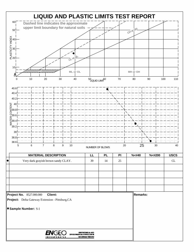
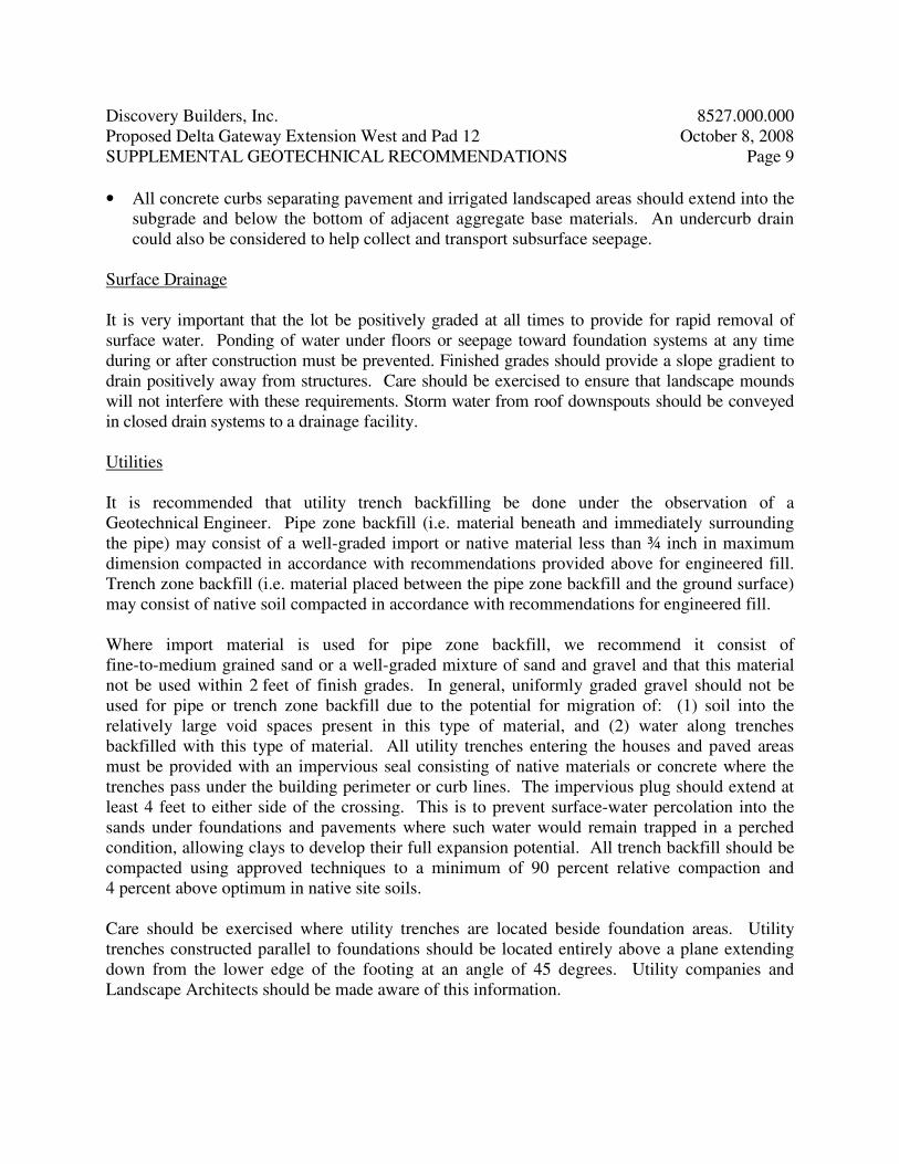
Very dark grayish brown sandy CLAY. 39 14 25 CL
8527.000.000
MATERIAL DESCRIPTION LL PL PI %<#40 %<#200 USCS
Project No. Client: Remarks:
Project:
Sample Number: S-1
PLA
STI
CIT
Y IN
DE
X
0
10
20
30
40
50
60
LIQUID LIMIT0 10 20 30 40 50 60 70 80 90 100 110
CL-ML
CL or OL
CH or OH
ML or OL MH or OH
Dashed line indicates the approximateupper limit boundary for natural soils
47
WA
TE
R C
ON
TE
NT
38.6
38.8
39
39.2
39.4
39.6
39.8
40
40.2
40.4
40.6
NUMBER OF BLOWS5 6 7 8 9 10 20 25 30 40
LIQUID AND PLASTIC LIMITS TEST REPORT
Delta Gateway Extension - Pittsburg,CA

EN GEO Incorporated
Project Name: Delta Gateway Extension Project Number: 8527.000.000
Tested By: GC Date: September 29, 2008
Measurements less than 15 mg/kg are reported as Not Detectable (ND)
mg/kg % by Weight
1 S-1 soil 33 0.003
SULFATE TEST RESULTS
CALTRANS Test Method 417
Water Soluble Sulfate (SO4) in
SoilSample Number Sample Location Matrix
Office: 2010 Crow Canyon Place, Suite 250, San Ramon, CA 94583
Laboratory: 2057 San Ramon Valley Boulevard, San Ramon, CA 94583 1