discussion on electric power supply systems for all
TRANSCRIPT

Received February 24, 2020, accepted April 3, 2020, date of publication May 6, 2020, date of current version May 18, 2020.
Digital Object Identifier 10.1109/ACCESS.2020.2991804
Discussion on Electric Power Supply Systemsfor All Electric AircraftHENDRIK SCHEFER 1, LEON FAUTH 2, (Member, IEEE), TOBIAS H. KOPP 3,REGINE MALLWITZ1, (Member, IEEE), JENS FRIEBE 2, (Member, IEEE),AND MICHAEL KURRAT3, (Member, IEEE)1Institute for Electrical Machines, Traction and Drives, Technische Universität Braunschweig, 38106 Braunschweig, Germany2Institute for Drive Systems and Power Electronics, Leibniz Universität Hannover, 30167 Hannover, Germany3Institut für Hochspannungstechnik und Elektrische Energieanlagen - elenia, Technische Universität Braunschweig, 38106 Braunschweig, Germany
Corresponding author: Regine Mallwitz ([email protected])
This work was supported by the Deutsche Forschungsgemeinschaft (German Research Foundation, DFG) through the Germany’sExcellence Strategy-EXC 2163/1-Sustainable and Energy Efficient Aviation under Grant 390881007. The publication of this article wasfunded by the Open Access Publication Funds of the Technische Universität Braunschweig.
ABSTRACT The electric power supply system is one of the most important research areas within sustainableand energy-efficient aviation for more- and especially all electric aircraft. This paper discusses the historyin electrification, current trends with a broad overview of research activities, state of the art of electrificationand an initial proposal for a short-range aircraft. It gives an overview of themission profile, electrical sources,approaches for the electrical distribution system and the required electrical loads. Current research aspectsand questions are discussed, including voltage levels, semiconductor technology, topologies and reliability.Because of the importance for safety possible circuit breakers for the proposed concept are also presentedand compared, leading to a initial proposal. Additionally, a very broad review of literature and a state of theart discussion of the wiring harness is given, showing that this topic comes with a high number of aspects andrequirements. Finally, the conclusion sums up the most important results and gives an outlook on importantfuture research topics.
INDEX TERMS Aviation, aerospace electronics, MEA, AEA, electric power supply systems,dc-dc power converters, power semiconductor devices, wide bandgap semiconductors, high voltage directcurrent (HVDC), circuit breaker, hybrid circuit breaker.
AEA All Electric AircraftALFCS Active Laminar Flow Control SystemANPC Active Neutral Point ClampedAPES Auxiliary Power Electronics SwitchAPU Auxiliary Power UnitATAG Air Transport Action GroupBMU German Federal Ministry for the Environment,
Nature Conservation and Nuclear Safetybti bias temperature instabilityCB Circuit BreakerCSCE Critical Short-Circuit EnergyDAB Dual Active BridgeDCB Direct Copper BondingEPAS European Plan for Aviation SafetyECS Environmental Control SystemEHA Electro-Hydraulic Actuators
The associate editor coordinating the review of this manuscript andapproving it for publication was Aniruddha Datta.
EMA Electro-Mechanical ActuatorsEMC Electromagnetic CompatibilityEMI Electromagnetic InterferenceEPS Expand Phase Shift ModulationeVTOL All-Electrical Vertical Take-Off and
LandingEXT-PWR External Power SupplyFAA Federal Aviation AdministrationFIT Failure in TimeGaN Gallium NitrideGPU Ground Power UnitHEMT High Electron Mobility TransistorHVDC High Voltage DCIATA International Air Transport AssociationIGBT Insulated Gate Bipolar TransistorsJEDEC JEDEC Solid State Technology
AssociationMEA More Electric AircraftMFFC Multifunctional Fuel Cell
84188 This work is licensed under a Creative Commons Attribution 4.0 License. For more information, see https://creativecommons.org/licenses/by/4.0/ VOLUME 8, 2020

H. Schefer et al.: Discussion on Electric Power Supply Systems for AEA
MMC Modular Multilevel ConverterMOSFET Metal Oxide Field-Effect TransistorsMPES Main Power Electronic SwitchMS Mechanical Switchpax PassengersPD Partial DischargePE Power ElectronicPoL Point of LoadRAT Ram Air TurbineSBD Shottky Barrier DiodeSCC Switched Capacitor ConverterSCWT Short-Circuit Withstand TimeSEB Single Event BurnoutSEE Single Event EffectSEGR Single Event Gate RuptureSi SiliconSiC Silicon CarbideSoC State of ChargeSPS Single Phase Shift ModulationSSCB Solid State Circuit BreakerSSPC Solid State Power ControllerSTARC-ABL Single-aisle Turboelectric AiRCraft with
Aft Boundary Layer propulsionSUGAR Subsonic Ultra Green Aircraft ResearchTID Total Ionizing DoseTPS Triple Phase Shift ModulationVFSG Variable Frequency Starter GeneratorWIPS Wing Ice Protection SystemZVS Zero Voltage Switching
I. INTRODUCTIONTwo key drivers for electrifying air transportation can beidentified: First, pollution as a result of the ever-increasingnumber of flights needs to be limited, if current climategoals are to be reached. Here, especially the high amountof CO2 emission by conventional jet turbines needs to bereduced [1]. Secondly, the availability of currently used jetfuel refined from oil is limited - therefore, new driving con-cepts or fuels need to be investigated. Additionally, pricesare expected to increase in the long term [2], which willresult in a lower profit margin, as fuel prices hold a largeshare in overall aircraft operation costs [3]. As a result, thereis a trend towards a more ecological alternative, which willultimately mean a strong electrification of aircraft. The firststep is the so-calledMore Electric Aircraft (MEA), whichwillincrease overall efficiency by replacing conventional solu-tions with electrically driven alternatives [4], [5]. In the nextstep, in the All Electric Aircraft (AEA) the thrust componentswill also be replaced with electric systems, prospectively in aseries hybrid concept for medium- to long-range applications.To make this concept feasible, progress in a multitude ofareas is needed. As batteries are a possible energy source forfuture AEA, a high overall efficiency is mandatory. There-fore, research in improved aerodynamics is necessary. Forweight savings, novel fuselage and wing materials have to
be considered. For the electrical systems, high efficiencyelectrical drives as well as high power density energy sourcesare needed [6]. Interconnecting the sources as well as theloads, which includes beside themotors additionally theWingIce Protection System (WIPS), the Environmental ControlSystem (ECS), the control flaps, avionics, hotel and galleyloads and more, requires a high efficiency energy distributionsystem. This electrical grid can therefore be seen as key driverfor energy-efficient aviation. It enables novel approaches foraircraft energy supply from source to load with new gridstructures and distributed energy generation systems. Electri-cal sources can be high energy density batteries and fuel cells,being already a wide area of current research [7]–[9]. Alsothe voltage level and frequency for the electrical grid need tobe considered, as they directly relate to the system topologyand overall weight. For reducing the current and therefore thediameter of the wiring harness, High Voltage DC (HVDC)grids are proposed [10]. While the here described voltages,although described as HVDC, do not exceed 540V(±270V),even higher DC voltages up to 3 kV(±1.5 kV) will be exam-ined in this publication. Based on this, an energy supplysystem for an AEA consisting of DC/DC converters, wiringharness and circuit breakers will be proposed. This systemwill be sized for the use in a typical regional commuteraircraft with less than 100 Passengers (pax). Challenges withregard to energy generation, conversion and distribution willbe highlighted, with a focus on the power electronics switchesand topologies, high power circuit breakers and wiring har-ness reliability. Especially challenges coming from the appli-cation in an aircraft environment, which is characterized bylow pressure, harsh temperatures and radiation, are identified.The feasible solutions are based on a high voltage distributiongrid, enabled by novel wide bandgap semiconductor deviceswith high breakdown voltage as well as special topologiesfor high voltages and high currents. For circuit breakers, newhybrid structures are discussed. Section II and III give anoverview of the current state of the art regarding the air trans-portation system. Section IV gives details on current MEAs.In Section V, advantages and disadvantages of a high voltagedistribution system will be shown, followed by an initialproposal for a high voltage grid for an AEA in Section VI.Power electronics devices based on Silicon Carbide (SiC) andGallium Nitride (GaN) and their special use in an aircraftenvironment are discussed in Section VII. Section VIII intro-duces different topologies for high voltage and high currentcircuit breakers, Section IX discusses challenges for a highvoltage wiring harness in an aircraft environment.
II. TRANSFORMATION TOWARDS SUSTAINABLEAIR TRANSPORTThe transformation of society towards a more sustainableuse of resources is the focus of a large number of researchprojects. A growing world population, decreasing resources,increasing demands on the quality of life, and changing livingconditions represent significant challenges for the presentand future generations on earth. Especially the environmental
VOLUME 8, 2020 84189

H. Schefer et al.: Discussion on Electric Power Supply Systems for AEA
conditions are fundamental for the existence of our soci-ety. An essential factor for the sustainable development ofhumanity is mobility with the help of individual and publictransport.
A. ENVIRONMENTAL IMPACTIn Germany, the transportation sector was responsible for18% of CO2 equivalents in 2016. In contrast to other sectorssuch as energy, industry, agriculture, waste management, andprivate households, the CO2 rose by 3% in 2017 comparedto the reference year 1990. According to the German Fed-eral Ministry for the Environment, Nature Conservation andNuclear Safety (BMU), 1.4% of emissions from the transportsector are attributable to national flights [11, page: 39] [12].
Civil aviation within Europe is responsible for 13.2%of CO2 emissions in the transport sector [13]. The Euro-pean Aviation Environmental Report 2019 shows a relativeincrease of 16% in CO2 emissions compared to the referenceyear of 2005 to 2017. A further increase of 42% is expectedaccording to current models. Nitrogen oxide emissions alsoshow drastic increases. Besides, the report shows only apositive development in noise reduction.
Worldwide, the impact of air traffic on the environmentis estimated to be 2% of the anthropogenic carbondioxides [14].
B. MARKET PROSPECTSThe International Air Transport Association (IATA) pre-dicts that passenger numbers will double from 2016 to2030 under liberal market conditions and political stimu-lus. Asia is expected to show high growth rates [15]. Cur-rently, only 10% of the world population has access to airtravel [16].
Another important criterion is the price development ofkerosene. According to a worst-case estimate, the price ofcrude oil could double by 2050. The kerosene price is directlylinked to the price of crude oil [17, page: 16]. CO2 taxesrelated to passengers and per 100 km are under discussion.
C. POLICY INSTRUMENTSThe Paris Agreement is an essential target for global climateprotection and the preservation of livelihoods. The agreementaims at a global warming of below two degrees Celsiuscompared to pre-industrial age [18]. The European Flight-path also addresses ambitious environmental protection goalsfor civil aviation. By 2050, the technologies are expectedto reduce CO2 emissions by 75% per passenger kilometer,nitrogen oxide emissions by 90%, and noise emissions by65%. The reference is a new type of aircraft from the year2000. These specifications support the Air Transport ActionGroup (ATAG) target [1, page: 15]. Further objectives of theFlightpath are
• emission-free taxiing,• air vehicles have to be designed and manufactured so asto be recyclable,
• Europe is established as a center of excellence for sus-tainable alternative fuels, including those for aviation,based on a robust European energy policy,
• Europe is at the forefront of atmospheric research andtakes the lead in the formulation of a prioritized envi-ronmental action plan and establishment of global envi-ronmental standards.
Noise and nitrogen oxide reduction addresses urban areasin particular. Many European airports have a ban on nightflights.
D. RESEARCH APPROACHESBased on the goals mentioned above, a series of researchprojects can be developed, which will lead to an evaluationof air traffic systems, flight physics, vehicle systems, energystorage, and conversion. Sustainable air transport requires alow carbon footprint, low noise footprint, high operationalsafety, and high reliability at low cost under the high com-plexity of the entire aviation system. Known vital parametersare the reduction of aerodynamic drag by new aerodynamicconcepts, reduction of structural masses by new materials,and integration of propulsion systems.
Synthetic fuel can be used for CO2-neutral air traffic. A fur-ther optimization is the electrification of the aircraft, whichcould lead to very low-noise and low-emission air traffic. Forthis purpose, power densities of electrical components mustbe increased, energy densities of electrical storage mediamust be improved, and sustainable generation and transportof electrical energy must be achieved.
The next section deals in detail with realized aircraft con-cepts, so-called MEAs, and well-known research projects onplatforms of hybrid aircraft. It derives the trend of electrifica-tion without referring to the aircraft category.
III. TREND OF ELECTRIFICATION INAIRCRAFT APPLICATIONSFig. 1 shows the predicted development of electrificationin commercial aviation. In this case, the electrical powerrequirement is plotted logarithmically over the year. Thereare numerous other research projects, such as All-ElectricalVertical Take-Off and Landing (eVTOL) or small regionalelectrified aircraft (e.g.: ZunumAero), which are not includedin this diagram.
For the listed commercial aircraft and research projects,the ratio of electrification is given. The ratio Pel
Pthof the elec-
trical power to the maximum thrust power in take-off is putinto relation. The thrust power is estimated here and is not astandard parameter in aviation industry.
A. AIRBUS A380The Airbus A380 can be classified among the MEA,it was commissioned in 2007 and had a maximum capacityof 853 seats (typical seating 4-class: 550 seats). The aircrafthas a cruising speed of 0.89 Mach and a range of 14, 800 km(8, 000NM) [19]. Hydraulic components are partly electri-fied, such as flight control systems. The increased electrical
84190 VOLUME 8, 2020

H. Schefer et al.: Discussion on Electric Power Supply Systems for AEA
FIGURE 1. Trend of electrification in aviation application.
power requirement is provided by four generators of the mainengines (600 kVA in total, PelPth
< 0.2%, excluding the Auxil-iary Power Unit (APU)) with an alternating voltage of 115V[20, page: 57]. 75 g CO2 per passenger kilometer are achievedby using expandedmaterials and reducing the structural mass.This airplane reduces noise emissions by 50% at take-offand three to four times less noise at landing compared to itsnearest competitor. The engines reduce noise emissions witha combined wing and landing gear design [19].
B. BOEING 787A further MEA is the Boeing 787-8 Dreamliner, launchedin 2011 with a maximum of 410 pax (typical 242 pax).In flight operation, a cruising speed of 0.85Mach, and arange of 13, 620 km (7, 354NM) is achieved [21]. In thistype of aircraft, a large number of pneumatic and hydraulicsystems were replaced by electric ones. Power electronicsand electrical machines with compressors replace huge pneu-matic loads, such as the WIPS and the ECS. Due to thehigh electrical power requirement, an on-board grid withan alternating voltage of 235V was implemented. The fourgenerators of the two main engines generate a total elec-trical power of 1MVA (without APU, Pel
Pth< 1.5%) [20,
page: 57]. Composite materials and an optimized aircraftstructure are also used. These technologies enable noiseemissions to be reduced by 60% and fuel consumptionby 20% [21].
C. E-FAN XE-FAN X is a project initially led by Airbus, Rolls Royceand Siemens. The first test flights are expected in 2021.The BAe 146 is powered by four engines. One propulsionunit is powered by a 2MW (PelPth
≈ 25%) electric motorand connected to the 3 kV on-board power supply via aninverter. It is a serial hybrid system; a built-in turbine drives agenerator in the fuselage [22], [23, page: 10]. The platform isdesigned to explore challenges such as thermal management,altitude, and dynamic effects in high-performance electricalpropulsion systems while maintaining high reliability andsafety [24].
D. NASA STARC-ABLNASA project Single-aisle Turboelectric AiRCraft with AftBoundary Layer propulsion (STARC-ABL) combines sev-eral experiences from projects such as Subsonic Ultra GreenAircraft Research (SUGAR) and N3X. For the first tests,the availability of the Turbofan N+ 3 technology is essential.The technology is expected to be available in the time frame2030 to 2035. With a cruising speed of 0.7Mach, a range of6, 482 km (3, 500NM), and 154 pax, the aircraft belongs tothe medium range [25, pages: 2-3]. It is a parallel hybrid,the engines below the wings generate thrust and electri-cal power. Thus, each engine generates electrical power ofroughly 1.5MW and is connected via an inverter to a 1 kVDC on-board power supply. The DC system is connected toa boundary layer ingesting tail-one thruster. The all-electricdrive has a power of roughly 2.61MW (PelPth
≈ 30%) and gen-erates thrust. Due to the installation situation, as a boundarylayer ingesting tail-one thruster, the engines can be optimizedunder the wings. The combination of smaller engines onthe wings and the boundary layer ingesting tail-one thrusterreduces the aerodynamic drag [26, pages: 2-3].
E. NASA N3-XAnother NASA project, N3-X, is strongly oriented towardsthe NASA Future Aircraft Goals N + 3. Another importantmilestone will be the availability of turbofan technology, anda maiden flight would be possible from 2040 [27, page: 3].The aircraft has a cruising speed of 0.84Mach, a distance of13, 890 km (7, 500NM), and carries 300 pax [28, page: 9].Studies show that the best possible weight reduction can beachieved using superconductivity and a DC on-board net-work of±2 kV [29, page: 197]. Besides, two generators with6.5MW each are operated per wing. Sixteen distributed elec-tric drive systems provide the thrust as After Fan Technology.The target is a nominal total electrical output 25MW (PelPth
≈
80%) [29, page: 135]. With the help of the Hybrid WingBody with Nacelle (HWB), the aerodynamic drag is reduced.The improvements will reduce fuel consumption by 60%and reduce nitrogen oxide emissions by 80% during take-off and landing [30, pages: 1-2]. A noise-optimized varianthas an estimated noise reduction of 64EPNdB under flightnoise standard ‘‘Chapter 4 standard cumulative margin noisereduction’’ [30, pages:19-20].
F. ESTIMATION OF THE AVAILABLE ELECTRICAL POWERThe orange arrow in Fig. 1 shows the trend towards electri-fication. MEA and Hybrid-electric Aircraft such as E-FANX and NASA STARC-ABL illustrate the trends. Accordingto these estimations, 10MW of electrical power could beimplementable in an aircraft in 2050.
A good system concept and HVDC transmission arerequired to enable this vision. For this approach, great effortsare required in search of electrical systems for aviation pur-poses. In 2050, it seems feasible to operate AEA in the shortand medium range.
VOLUME 8, 2020 84191

H. Schefer et al.: Discussion on Electric Power Supply Systems for AEA
For the NASA N3-X concept, a major technological leapmust follow, involving the use of a combined HVDC trans-mission with superconductivity. In addition, the power den-sities of power electronics and electrical machines mustincrease drastically, achieved for example by using newmate-rials and superconductivity. These approaches require highinvestment costs in these research projects.
The following section presents the state of the art by a largecommercial MEA.
IV. STATE OF ART: ELECTRICAL ARCHITECTURE OF ALARGE COMMERCIAL MORE ELECTRIC AIRCRAFTTwo well-known commercial concepts of a MEA could beidentified from Section II. The aircraft aims at saving fuel inorder to minimize airline costs and carbon dioxide emissions.Another goal is to reduce aircraft noise. MEAs are the firststeps towards sustainable commercial air traffic, as definedby the overall social goals.
In the following section, the aircraft concept is presentedfrom the point of view of the electrical components, althougha great deal of engineering effort is also involved in optimiz-ing the structural mass, the aerodynamic concept, and otherdisciplines. It is shown how the on-board grid has changedin comparison to a typical aircraft and the influence involvedon the overall system. The secondary power systems in anaircraft, such as hydraulics, pneumatics, mechanics, and elec-tricity, have an influence of approximately 5% on the totalfuel consumption. They are essential for safe flight operationsand passenger comfort [23, page: 1].
Fig. 2 shows the on-board grid of a large commercialaircraft, based on the Boeing 787, and is supposed to illustratethe ongoing development. Individual components are repre-sented schematically in the figure. In the presented aircraft,many pneumatic and some parts of hydraulic componentshave been replaced by electrical ones. A better conditionmonitoring and controllability characterizes electrical com-ponents in comparison to bleed-air based systems so thatconsumption-oriented energy is available. Besides, individualsubsystems can be switched off easily in the event of afault [31, page: 8].
The MEA concept uses the Boeing 787’s no-bleed systemarchitecture. By replacing the bleed air, better fuel efficiencyis achieved due to better use of secondary energy, mainte-nance costs are reduced due to the exchange of pneumaticsystems, and higher reliability is obtained with modern powerelectronics and component reduction [32, page: 6]. A conven-tional aircraft has a bleed-air system with roughly 1.2MW[33, page: 2]. This method saves approx. 3% of the fuel [32,page: 6]. Compared to conventional architectures, weight andlifecycle costs are reduced.
A. MAIN ENGINE AND GENERATORIn traditional aircraft, the bleed air is removed from the tur-bine, resulting in inefficient utilization. In contrast, a moderncommercial aircraft replaces the bleed-air extraction systemwith larger Variable Frequency Starter Generators (VFSGs).
The replacement requires a higher electrical system perfor-mance [33, pages: 2-3]. Fig. 2 shows two VFSGs per turbinewith an output of 250 kVA each. Thus, an electrical systempower of 1MVA is available [32, page: 9].
In traditional aircraft, the turbine is started via the pneumat-ics (so-called Main Engine Start); in MEA, this is achievedelectrically via starter converters. The electrical power isprovided by the APU, the other turbine or the External PowerSupply (EXT-PWR). The jet engine can be started via theAPU or the other already started jet turbine or a groundvehicle [32, page: 9-11].
Another difference to the typical aircraft is the variableelectrical frequency, which is within the range of 360 to800Hz in the represented MEA. In previous aircraft, an Inte-grated Drive Generator (f = 400Hz) is used, which consistsof a generator and a Constant Speed Drive. However, today’sthree-phase VFSG uses a fixed ratio gear connected to thehigh-pressure turbine stage. No power electronics are neededfor this approach. Permanent magnet synchronous generatorscan be an alternative to achieve a higher power density of8 kVA/kg (currently 3.3 kVA/kg, VFSG) [23, page: 652].The proximity of the turbine to the electrical machine requiresproper thermal management. A further increase in the elec-trical system performance lacks a multiple spool concept(currently: high-pressure stage of main engine is used) [23,page: 653].
B. AUXILIARY POWER UNITThe APU turbine stage at the rear does not contain anypneumatics. The APU also uses a VFSG and is less com-plex than its predecessor. In typical aircraft, the APU has apneumatic system for starting the main engines [32, page: 11][20, page: 57].
Efforts are being made to replace the APU with a Multi-functional Fuel Cell (MFFC) system. The system generateselectrical energy and heat. In addition, water is available tothe aircraft through a treatment process. Another possibilityof the use of MFFC is the generation of nitrogen. Nitrogencan be used as an inert gas to prevent the ignition of the fuelin the tank [34, page: 20-28] [35, pages: 5] [36, pages: 1-3].
C. ELECTRICAL POWER SUPPLYBecause the electrical system power has increased dramati-cally by replacing the bleed air, the effective alternating volt-age of the three-phase system is increased to 235V (typically115V). Fig. 2 shows a distributed redundant electrical powersystem, which is centralized in a typical aircraft. Further-more, for compatibility reasons, the voltage level 115V ACand 28V DC is used, since many components are designedfor this voltage level and many airports provide this exter-nal power supply. The DC voltage of ±270V is mostlygenerated by passive three-phase bridge rectifiers (so-calledAuto Transformer Rectifier) and is used to supply compo-nents with high electrical power, such as the compressors forthe ECS. [32, page: 9].
84192 VOLUME 8, 2020

H. Schefer et al.: Discussion on Electric Power Supply Systems for AEA
FIGURE 2. Electric schematic of MEA.
VOLUME 8, 2020 84193
H. Schefer et al.: Discussion on Electric Power Supply Systems for AEA
One research effort for MEA is to increase the voltageof the electrical power supply system to 540V DC. Thestandards, such as MIL-STD-704F, have to be adapted. Arc-ing represents a major risk under such harsh environmentalconditions.
A further challenge is the increasing demand for power andthe associated power generation. Low-speed turbine stagescould be used. Wide bandgap semiconductors represent analternative to silicon. The wider fundamental wave of theelectrical machine at low pressure stage and the increased on-board voltage pose a challenge for conventional semiconduc-tor materials [23, page: 655].
D. ELECTRICAL LOADSFig. 2 contains large electrical loads. A conventional air-craft uses bleed air for the ECS and WIPS. The ECSensures air exchange, regulates the interior temperature, andadjusts the air pressure. In the Boeing 787, the ECS isrepresented by large and small compressor units and fans[32, page: 11]. The system requires a compressor capacityof 4 · 100 kW [20, page: 57].
Heating blankets replace the typical WIPS and reduce thepower consumption by half. Constant anti-ice protection orsequential de-icing is achievable [32, page: 11].
The hydraulic system controls the control surfaces andlanding gear. For this purpose, two large compressor unitsdeliver a pressure of 34.5MPa at approximately 7.95m3/h.Additional electric no speed controllable compressors and themain engines provide additional hydraulic system pressure.Due to the high system pressure, the hydraulic componentsare smaller and save space and weight [20, page: 6].
Electric components partly replace the hydraulic sys-tems, where Electro-Mechanical Actuators (EMA) andElectro-Hydraulic Actuators (EHA) supplement the system.EHA should preferably be used for primary control sur-faces, such as rudders, ailerons, and elevators. The sec-ondary control surfaces, such as flaps and slats, are pri-marily responsible for efficiency and comfort. Operation viaEMA is possible, although there is a risk of jamming [33,page: 3]. The brakes in the Boeing 787 can also be operatedvia EMA [20, page: 59].
Further optimization potential has the Electrical Taxiing,which avoids nitrogen dioxide, noise, and unnecessary fuelconsumption during taxiing. Also, the aircraft is independentof ground vehicles [20, page: 61-61].
The Active Laminar Flow Control System (ALFCS)accommodates a further increase in the efficiency of acommercial aircraft. With the help of electric compressors,the aerodynamic drag of the aircraft is reduced [37].
In the next Section V, the challenges posed to a highvoltage electrical power supply system by the harsh environ-mental influences are highlighted.
V. HVDC GRIDS FOR AIRCRAFT APPLICATIONIn this section, a supply grid voltage for future AEAs willbe proposed. Only DC grid structures are considered, as allenergy sources in an AEA are most likely to be DC (fuel
cells and batteries). Furthermore, no overrating of powerconverters due to reactive power is necessary and the systemcomplexity is reduced, as most of the converters can beDC/DC converters. Inverters are only used for motor loadslike flight control systems, cooling liquid pumps, e-taxi andpropulsion. No rectifiers with a large volume due to powerfactor correction stages are needed. At first, estimations onpower demand are given based on data for standard regionalcruiser airplanes with a capacity of 100 pax. The overallpower needed is separated in continuous and dynamic powerdemand. Continuous power demand is needed by lights, ECS,avionics, hotel and galley loads, and the WIPS. Dynamicloads are flight control actuation systems. The propulsionsystem requires a mostly continuous power during cruising,the power demand for climb and descent is higher. For theWIPS, a power demand of 35 kW can be estimated, basedon data given for a Boing 787 [38]. Hotel and galley loadscombine to a few kilowatts, the ECS has an estimated powerdemand of 150 kW [39]. For flight control systems, the peakpower demand is 20 kW [40]. The demand of auxiliary powerfor the electrical system itself, namely pumps for liquidcooling and fuel cells, is still unknown. In total, all non-propulsive loads of a regional cruiser airplane are expected tobe less than 300 kW. For a state-of-the-art MEA (Boing 787,400 pax), the power demand of all electric loads is given as1MVA [20]. Compared to this number, the above estimatedvalue seems reasonable. The largest power demand comesfrom the propulsion system. Here, a peak power of approxi-mately 3.7MWduring take-off and climb, and descent can beassumed, based on conventional turbines for a short-range air-craft [41]. At cruising speed and altitude, a continuous powerof approximately 0.6 times the peak power is needed [42].Based on this data, an overall peak power demand of 4MW isestimated. In the literature, voltage levels of 540V(±270V)are proposed. This value is mainly determined by the cur-rently available technology. TheAPU and the generators havea three-phase output with a voltage of 230V, which can berectified to a DC voltage of 540V or ±270V without theneed of additional DC/DC converters or transformers [10].For future AEAs, APU and Ground Power Unit (GPU) canbe replaced with newer technologies like on-board fuel cellsor electric charging at the airport.
As a result, an increased voltage level of 3 kV(±1.5 kV) isproposed in this paper. This has the advantage that the currentper conductor is decreased, therefore, the conductor diameteris smaller. As an example, by applying a high grid voltage of3 kV, a current of 617A is needed to supply a peak power of1.85MWfor one propulsor. For a lower grid voltage of 540V,a current of nearly 3.5 kA would be necessary. Consequently,the conductor mass of high power transmission lines can bereduced by a large factor. In the same time, current stress ofthe semiconductors is reduced, while increasing the require-ments in power electronics packaging, as a high insulation isnecessary.
Especially for application in aircraft, environmental influ-ences cause stronger restrictions than for ground applications.
84194 VOLUME 8, 2020

H. Schefer et al.: Discussion on Electric Power Supply Systems for AEA
FIGURE 3. Critical field strength in dependency of altitude.
At a typical cruising altitude of 6 km for regional aircraft,the air pressure is reduced to less than half of the air pressureat sea level, while the temperature is decreased to 250K [43].As a result, the critical field strength is drastically reducedaccording to Paschen’s Law [44]. This is slightly compen-sated by the lower air temperature, which increases the criti-cal field strength. In the fuselage, air pressure is controlled bythe ECS to a minimum value of 760 hPa, which is equivalentto an altitude of approximately 2.5 km (see Fig. 3). For non-pressurized locations, the critical field strength at a flightaltitude of 6 km is reduced to 17.8 kV cm−1. In the fuselage,the critical field strength is 25 kV cm−1, as long as the ECSis fully functional. In case of failure, the pressure can evendrop to ambient conditions. Power electronic systems needto be functional under these conditions. Therefore, creepageand clearance distances have to be designed to withstand thelower air pressure. This leads to special designed packagesfor power electronics. Another possibility is the potting ofelectronic systems. Consequences on the wiring harness arefurther discussed in Section IX.
Humidity is another environmental effect, which can havean impact on the applicability of high voltage supply grids.Energy transmission systems and power electronic devicescan be affected bymoisture by short-circuiting of the contactsthrough condensation, degrading the insulation materials forcables and silicone gel used in power electronic modules,and reducing the blocking voltage of power semiconductorsthrough electrochemical migration and aluminum corrosion.The bias voltage has a strong impact on the lifetime ofpower semiconductor modules under high humidity. Devicesbiased at 90% of their blocking voltage capability showed anaccelerated aging with a factor of two compared to devicesbiased at 65% of their blocking voltage capability. As powerelectronic devices are usually operated below 60% of theirrated voltage, a long lifetime of the devices can be expected.
This is further supported by the fact that the relative humidityof the air inside the fuselage is below 20%, as it is conditionedby the ECS. For power electronic systems placed in the wingsor the nacelle, dehumidifiers have to be considered as seen ininverters for wind energy systems.
Next to air pressure and humidity, radiation limits theapplication of high voltage systems in aircraft. Radiationeffects can be caused by primary or secondary sources. Pri-mary radiation is direct cosmic radiation (mainly protons andα-particles). At typical flight levels, cosmic radiation formsa neutron shower via spallation at atmospheric molecules,the so-called secondary radiation. As a result, damage dueto radiation can be divided in two effects. Firstly, deviceparameters can be altered because of the Total Ionizing Dose(TID). For given travel routes, the TID can be estimated basedon radiation data [45]. For example, a standard short-rangeflight in an altitude of 6 km can result in a radiation dose of200µSv h−1 [46]. Based on published data, a strong impactof the radiation dose on semiconductors used in short-rangeaviation is not expected. In [47], Si Insulated Gate BipolarTransistors (IGBT) under radiation are investigated. By usinga gamma radiation source, reduced gate threshold voltageand reduced turn-on and turn-off times could be observed,combined with a higher voltage overshoot at turn-off. How-ever, for a reduction of the gate threshold voltage of 1V,a flight time of above three million hours under abovemen-tioned conditions would be necessary. Current research on theeffects of radiation onGaNdevices is, for example, conductedby the NASA [48]. As for Si, parameter variations due tothe TID are unlikely to occur during the lifetime of powerdevices for the application in aviation. This is confirmed byresearch done in [49], [50] and [51]. Under heavy irradiation,drain saturation current, transconductance and gate thresholdvoltage are reduced, the drain to source breakdown voltageincreases. However, the proton flux used in the acceleratedtests of 2× 1015 cm−2 is equivalent to decades of operationin low earth orbit. As a result, it can be concluded that deviceparameter alteration due to TID is of no significance forapplication in aircraft.
Secondly, power electronics can fail due to a single neu-tron hitting the device (Single Event Effect (SEE)). If thesehigh energy neutrons hit a silicon ion, a conductive plasmacan be formed, which spreads throughout the device [52].This effect is dependent on the applied drain-source voltage.The device will be short-circuited by this discharge. Duringthis time, the self-heating of the device can lead to a non-reversible destruction. As only a single event is necessary,the probability of failure depends on the availability of highenergy neutrons, therefore on the neutron flux, which showsa dependency on the altitude, the geomagnetic location andon the solar activity. For a given location, the neutron fluxin an altitude of 6 km can be increased by a factor of about70, if compared to sea level [53]. As an example, estimatedFailure in Time (FIT) rates for 1.7 kV SiCMetal Oxide Field-Effect Transistors (MOSFET) in dependency of the altitudeare given in Fig. 4. Data is based on results in [54]. It can be
VOLUME 8, 2020 84195

H. Schefer et al.: Discussion on Electric Power Supply Systems for AEA
FIGURE 4. Reduction of drain source voltage for higher altitudes.
seen that in order to achieve a FIT rate of 1 (one failure in 109
hours ) at a flight level of 6 km, the grid voltage needs to bebelow 60% of the device breakdown voltage.
Generally, power semiconductors made of GaN and SiCpromise better resistance to radiation than conventionalsilicon devices. For instance, the displacement energy ofboth SiC and GaN is considerably higher than for silicon[55]–[57].More details on the behavior of GaN and SiC underradiation are given in Section VII-D. Based on the aforemen-tioned results, for a DC grid voltage of 3 kV, semiconductordevices or combinations of single devices with a blockingvoltage of at least 6 kV are necessary. For example, first ver-sions of 6.5 kV SiC MOSFETs are currently under investiga-tion for drivetrains in railway applications [58]. Alternatively,multilevel inverters made of devices with lower blockingvoltage can be applied, for example, Active Neutral PointClamped (ANPC), Switched Capacitor Converter (SCC), orModular Multilevel Converter (MMC). The MMC configu-rations can be especially beneficial for motor inverters, as thevoltage slew rate compared to conventional solutions can bereduced while still maintaining high switching speed and lowswitching losses [59], but they are usually of large volumeand weight and therefore not suitable for aircraft applications.Nevertheless, newest research on power density improvementshow significant advancements in the passive componentsbased on quasi two level operation and nonlinear inductordesigns [60]. In Section VII, more details will be given. Afterall, these solutions are of high complexity and investmentcosts, and for high voltage SiC MOSFETs, the electric per-formance still needs to be investigated.
Under these circumstances, a careful selection of the volt-age levels is needed. As shown before, the main powerdemand during operation arises from the propulsion system.For this reason, a dual-zone high voltage grid is a viable solu-tion. For supplying power to the propulsors, a voltage level of3 kV can be selected, in order to reduce the maximum current
and therefore volume and weight of the wiring harness. Forlower power loads, a DC voltage of 800V can be sufficientlyhigh, by still reducing wiring harness dimensions and atthe same time lowering system complexity. For example,a three-level ANPC made of 1.2 kV SiC MOSFETs providessufficient blocking voltage capability based on the afore-mentioned considerations on cosmic radiation. A detaileddrawing of a viable grid structure is given in Fig. 5.
VI. INITIAL PROPOSAL: ELECTRICAL ARCHITECTURE FORAN ELECTRICALLY POWERED SHORT-RANGE AIRCRAFTThis topic deals with the realization concept of an elec-trically powered aircraft, the necessary development steps,and the research approaches regarding electric components.An initial electrical architecture, as given in Fig. 5, is pro-posed. With the help of the estimations of electrification, seeSection III, it can be possible to realize an electrical powerof 10MW in a high voltage electrical power supply systemby 2050. Based on this initial diagram, the electrical sources,the on-board grid, and the loads are discussed.
A. MISSION PROFILE OF A SHORT-RANGE AIRCRAFTThree different aircraft types are available: short-range,medium-range, and long-range. Mission profile data origi-nated from the design and optimization strategy in publi-cation [61]. The study concludes that even by optimizingthe medium and short range, Flightpath 2050’s targets willnot be met. The short-range aircraft is far below the Euro-pean Flightpath, although the overall drag of the aircraft isreduced by 47% as a result of aerodynamic optimizations[61, page: 15]. The use of new energy storage systems andalternative propulsion concepts is proposed. In future studies,the influence of substitution by electrical components has tobe investigated. With these assumptions, further algorithm-based optimization of the electrical system can be carriedout. The publication [62] shows the system optimization ofa hybrid-electric aircraft. In addition, fault tree analyses haveto be performed in order to determine reliability. The aim isto achieve a significant weight reduction with a high faulttolerance.
Furthermore, the influence of small distributed drives onaerodynamics should be verified. It may also be possible touse free-flow drives or boundary layer ingestion. Alternativeelectric drives and flexible power supply create new degreesof aerodynamic design freedom [25, page: 2].
The proposal for a short-range aircraft is designed for100 pax, has a range of 1, 000 km (540NM) and reaches acruising speed of 0.44Mach at a flight altitude of 6, 000m.Based on initial estimates, a shaft power of 3.7MW isrequired and the energy storage is to be designed as a battery.Shaft power is within the technology estimation of less than10MW in 2050, as given in Section III.
B. ELECTRICAL SOURCESThe proposed power supply system structure includes notonly batteries but also fuel cell systems. Despite the further
84196 VOLUME 8, 2020

H. Schefer et al.: Discussion on Electric Power Supply Systems for AEA
FIGURE 5. Electric schematic of AEA.
VOLUME 8, 2020 84197
H. Schefer et al.: Discussion on Electric Power Supply Systems for AEA
development of battery technology, the finite charging capac-ity at the airports is a known limitation. Little ground timesrequire extensive charging capabilities, which must be avail-able at the airports.
1) CHARGING AT AIRPORTSFor an estimation, a constant power of 3MW over the entireflight profile (without take-off and landing process; withoutpeak power) is assumed. The travel time is 1.5 h, whichrequires an energy of 4.5MWh (without efficiency chain:electric machine, inverter, cable layers, converters, and bat-tery). To get the aircraft airworthy again within 30min (cer-tain State of Charge (SoC)), a charging capacity of 9MWis required. It is also assumed that five small aircrafts willbe handled at the same time. This leads to an electricalconnection of the airport of 45MW only for five short-rangeaircrafts. 45MW is an enormous power input for today’s largeEuropean airports. Long aircraft downtimes due to a moremassive fleet are not very attractive for airlines.
A replacement battery concept would be a possible alterna-tive to avoid the aircraft downtimes. A substantial electricaloutput is nevertheless required, but could be well combinedwith regenerative energies.
The authors of this paper prefer the use of highly com-pressed or liquid hydrogen to overcome long downtimes. Thehydrogen has to be produced from renewable energies, oppo-site to the conventional steam reforming process. A hydro-gen economy grid could support transport from generationunits (e.g., decentralized electrolyzer at wind power plantsto airports). An upcoming decentralized grid needs storagefacilities, whereby hydrogen production with electrolyzerscould be a possible approach. Today, many wind turbines arestill being phased out at low electricity demand. Accordingto the report of the German Federal Wind Energy Associa-tion, 5.518 TWh were regulated in 2017 (wasted energy) [63,page: 2]. A significant disadvantage lies in the long and weakefficiency chains from the generation of electrical power tothrust.
2) BATTERYThe estimated technological limit for the pure use of batteriesin an aircraft is a gravimetric energy density of 500Wh/kg[64, page: 27]. Many scientists are working on increasing theenergy density of batteries (2017: 350Wh/kg [65, page: 1]).An improvement in energy density has already been achievedthrough the dispersing process of the sulfur cathode mate-rial and calendering process parameters for compacting thecathodes [65, pages: 6-7]. For the year 2030, a gravimetricenergy density of 500Wh/kg (volumetric energy density1000Wh/l) of solid-state battery (generation 4) is predicted[66, page: 9]. Another possibility is the combination of siliconand sulfur. For a fast charge, the chemical and mechanicalstability for Si wires from the solid electrolyte interface isof particular interest [67]. Lithium-air batteries could alsobe a key technology as they promise high theoretic energydensities (year 2030+: practical densities of 500Wh/kg ≤)
[64, page: 7]. With these approaches, an environmentallyfriendly and cost-effective battery can be built.
3) FUEL CELLHighly compressed (e.g., 70MPa) or liquid hydrogen is par-ticularly interesting due to its gravimetric energy density(without tank 33.3 kWh/kg, gasoline about 11.6 kWh/kg),but is characterized by a relatively low volumetric energydensity [68]. Liquid hydrogen could also be used for super-conductivity in the on-board grid. Superconductivity requiresvery low operating temperatures, which could be ensured bythe liquid aggregate state of hydrogen. The fuel cell systemcurrently still has small power densities of 2 kW/kg [34,page: 11]. Through the use of new materials, a power densityof 10 kW/kg is to be achieved for the year 2050 [35, page: 6].
A problem is its relatively poor efficiency. At the nominalpoint, the fuel cell has an efficiency of about 60%. For exam-ple, assuming the fuel cell stack has an electrical output powerof 3MW, there is a waste heat output of 2MW. A portionof the resulting waste heat can be used as heat output for theWIPS and ECS. Dissipating unused heat from the aircraft willbe a challenge for the entire aircraft design. Waste water canbe partly used as service water. However, the unused water inthe aircraft cannot be drained during the flight phase; it hasto be stored.
For the application of fuel cells in aviation, the functionalreliability and the hazard-free operation has to be ensured.It can be deducted, that fuel cells are generally suitable forthe application in any vehicle propulsion. Fail-safe operationcan be guaranteed by paralleling multiple fuel cell systems asshown in Fig. 5. Hydrogen used as fuel has to be consideredas potential safety hazard. Hydrogen will leak faster throughbreaches in the storage tank than any other gas. As a result,tanks have to be closely monitored during operation andmaintained regularly. Small quantities of escaped hydrogenare relatively harmless because it disperses rapidly and istherefore unlikely to accumulate in the concentration requiredfor detonation. The ignition temperature of 560 ◦C is higherthan for jet fuel, but, like other gases, hydrogen can always beignited by a spark. In the end, hydrogen poses similar safetyhazards as other liquid and gaseous fuels and needs thereforeto be handled with special care.
4) COMBINATION OF FUEL CELL AND BATTERYThe wiring system topology in Fig. 5 contains four fuel cellsystems with batteries to overcome long downtimes. Thewider fuselage contains the batteries and fuel. Two sourcecombinations are responsible for one side. From the missionprofile-based analysis, the constant performance during theflight phase is to be covered by the fuel cell system. With thehelp of the batteries, the peak load during take-off is covered.The fuel cell is kept at a power level as constant as possibleso that the battery can also be charged by the fuel cell systemduring flight operation. When landing, the battery is chargedmore strongly due to the low required load. This approach
84198 VOLUME 8, 2020

H. Schefer et al.: Discussion on Electric Power Supply Systems for AEA
only needs a low charging power to be applied during groundtime. Further operating strategies are conceivable.
Circuit breakers are represented by the hybrid switch,which provides galvanic isolation. Disconnecting DC circuitsis a challenge because of the lack of the natural current zerocrossing. The hybrid circuit breaker is mounted directly onthe batteries in order to be able to switch off quickly andwithout large cable impedance in the event of a short circuit.The short-circuit behavior of the fuel cell is currently beinginvestigated.
In order to integrate the fuel cell in an optimal operatingwindow and into the high voltage electrical power supplysystem, a power electronic converter (MEA, 2013: 5 kW/kg[69, page: 10]) is required. The stack level of the cells has asignificant influence on the converter topology.
The integration of the batteries into the electrical powersupply system is also significantly influenced by the stacklevel. The question arises whether a converter is necessaryhere. Without converters, the high voltage electrical systemvoltage would be dependent on the SoC of the batteries.In addition, load flows and SoC of the distributed batterysystems can be better controlled by power electronics. A largenumber of variants to integrate fuel cells into the on-boardpower supply system is possible. Further investigations haveto be done.
C. ELECTRICAL DISTRIBUTION SYSTEMThe electrical power supply system, as given in Fig. 5, con-sists of two primary voltage levels (3 kV and 800V). DC volt-ages are preferred to decouple sources and loads. We proposeseveral voltage levels. Power electronic converters enable anenergy change between several voltage levels.
1) 3 kV DC VOLTAGEThe 3 kV level (±1.5 kV) connects the large loads, especiallythe electrical drive of the aircraft. The sources should belocated very close to the inverters, which enables the shortestpossible cable lengths.
The voltage for the transmission of such high power shouldbe as high as possible to reduce weight. The design of theinsulation is an essential criterion for avoiding arcing. Dueto the harsh environmental conditions (temperature, humid-ity, and pressure), creepage and clearance distances changedrastically, as given in Section V. It represents a significantchallenge for the design of power-dense power electronicsand electrical machines.
Evidence of safe operation must be provided in furtherinvestigations - the voltage level results from the possiblebreakdown voltage capability of future wide bandgap semi-conductors (6.5 kV). An important design criterion of powerelectronics is the consideration of cosmic radiation, as givenin Section V. As there is a less danger due to cosmic radia-tion during ground time (sea level), it would be possible toincrease the on-board voltage for a possible charging process(e.g., 3.6 kV or even higher).
2) 800 V DC VOLTAGEA hybrid circuit breaker allows disconnecting the power sup-ply in the event of a fault. Two isolated converters generate the800V (±400V) level, which is available for smaller loads.The insulation is less complex compared to 3 kV (±1.5 kV).The approach is to be close to the voltage in automotive, pho-tovoltaics, etc. SiC semiconductors with a breakdown voltageof 1700V are preferable, as given in Section V. Otherwise,a combination of SiC andGaN can be used to achieve a higherpower density. A high power density could also be reached inthis power range (100 kW ≤ P < 200 kW) by a pure GaNapproach.
The mains can be separated by two hybrid circuit breakersin case of possible fault conditions. Another hybrid circuitbreaker can separate the grid structure in the event of a majorfailure.
3) LOW VOLTAGE LEVELThe 28 V on-board power supply for the avionics is generatedfrom the 800V (±400V) on-board power supply. Two iso-lated converters are available to generate the 28V. A hybridcircuit breaker per string ensures fail-safe operation.
Distributed isolated converters provide electrical powerfor the galley, multimedia applications, lighting, etc. Theconverters connect the 800V electrical power supply with thelow DC voltage.
Converters based on GaN are beneficial for generating thelow voltage level and the 28V for avionics. High switchingfrequencies (200 kHz ≤ fs < 1MHz) at lower power levelscan lead to very power-dense converters.
D. ELECTRICAL LOADSThe largest electrical load is represented by the electri-cal drives (electrical machines 2017: 10 kVA/kg, 2050:40 kVA/kg for long-range aircraft [23, page: 655]) gener-ating the thrust. An output of 3.7MW of mechanical shaftpower per engine is required. The publication [70] presents ahybrid ANPC inverter (SiC and Si) with a power density of12 kVA/kg. A summary of NASA’s research projects on newmachine concepts and inverters with very high power densitydata is given in the publication [71]. For example:
• Inverter: General Electric
– continuous power: PN = 1MW– specific power goal: 19 kW/kg
• Electrical Machine: NASA Glenn Research Center
– continuous power: PN = 1.4MW– specific power goal: 16 kW/kg
The smaller loads are the ECS (P = 150 kW) and theWIPS (P = 35 kW), as estimated in Section V. The primaryand secondary control surfaces are operated by EMA, EHA.Hydraulic pumps, which generate the system pressure, arealso used. The hydraulic system supplements the operationof the control surfaces and enables the landing gear to beextended.
VOLUME 8, 2020 84199

H. Schefer et al.: Discussion on Electric Power Supply Systems for AEA
For emission-free taxiing, an inverter-controlled wheel hubmachine is available. Furthermore, distributed isolated con-verters generate a DC voltage for small low voltage loads.
VII. POWER ELECTRONICSThe AEA proposal, as given in Fig. 5, contains many powerelectronic components, such as different DC/DC convertersand inverters.
This publication focuses on DC/DC converters in the on-board power supply system of an AEA. Different types ofconverters are required for the DC on-board power supply tooperate at different voltage levels.
Hybrid circuit breakers are another field of application forpower semiconductors. The DC on-board network requirescircuit breakers which can safely disconnect parts of thepower supply in the event of a fault. Hybrid switches use Sili-con (Si)-based semiconductors to extinguish the arc, as givenin Section VIII.
In aviation, semiconductors are subject to harsh environ-mental influences, such as low temperature, low pressure,low humidity, and cosmic radiation. The replacement ofconventional components requires a particular high powerdensity. Besides, the components have to be fault-tolerant andhighly reliable. Special conditions and component targets arecontrary.
A. SEMICONDUCTOR TECHNOLOGYApplications differ in power and voltage range. The mostsuitable semiconductor is used, which allows the highest effi-ciency in this power and voltage range at a specific switchingfrequency. Fig. 6 shows the different power levels correlatingwith their typical range of switching frequencies and thetypically used semiconductor. The physical limit of silicon-based components in terms of high power and high switchingfrequency is reached. The power density of components isa particular focus of aviation. A high switching frequencyof the semiconductors enables a weight reduction of passivecomponents. Further essential criteria are the current carryingcapacity and the voltage blocking capability of the semicon-ductors. Materials, such as SiC and GaN, offer an increase inthe working range due to their physical properties. Silicon-based semiconductors also continue to be of interest for somecomponents.
1) SILICONSilicon-based semiconductor components have been undercontinuous development for almost 50 years. This technologyhas opened up a multitude of different fields of application.The further development of various technologies, such asIGBT and Si-based MOSFET, covers a wide power range.
For example, Si MOSFETs with trench gate structuresdominate the market up to 600V [72, page: 1]. A furtheroptimization of the MOSFET structure is the so-called superjunction.
The IGBT covers a market segment from 600V to 6.5 kV.For blocking voltages up to 6.5 kV, the IGBTs are based on a
FIGURE 6. Wide bandgap semiconductor vs. Si-based semiconductors.
field stop and injection enhancement. However, the IGBT hasreached its physical limits of the blocking voltage capabilityat 6.5 kV. The silicon-based components have an operatingtemperature of less than 175 ◦C, and the switching speed islimited [72, page: 1].
The reliability of the components has been dramaticallyimproved through the manufacturing process and the mount-ing and joining technology. Furthermore, the parts have beentested over many years in a wide range of applications[72, page: 1].
2) SILICON CARBIDESiC, a wide bandgap semiconducting material, could be apossible technology to achieve high power densities. Thehexagonal crystal structure 4H offers the largest bandgap ofSiC compounds. Compared to Si, there is not only a higherbandgap, but also a better thermal conductivity due to thesmaller intrinsic carrier density. Furthermore, there is also ahigher critical field strength of SiC, which leads to a smallerdrift layer thickness. A smaller chip area with equal conduc-tion resistance can be achieved by high doping of the driftlayer. The smaller chip area, in turn, leads to lower parasiticcapacitances, enabling a higher slew rate [72].
In addition to the abovementioned excellent properties ofSiC, the compound has a stable native oxide. However, in theearly beginning of the SiC technique, only low channelmobil-ities could be achieved. The problemswere high interface trapdensities. A significant reduction of the trap densities at theSiC/SiO2 interface was achieved by post-oxidation annealingin the manufacturing process in NO gas. Trap densities couldbe further reduced by a combination of NO and hydrogenannealing [73].
In many applications, such as regenerative energy technol-ogy and electric mobility, market entry has been expected foryears. SiC wafers are 30 times more expensive than Si wafers(data of the year 2015). The production is very complicatedbecause SiC has a polytypism crystal structure and extremethermodynamic properties [72], [74]. CREE has planneda factory for 8" wafers in 2024 (currently 6") [75]. Si isavailable in 12" wafers.
84200 VOLUME 8, 2020

H. Schefer et al.: Discussion on Electric Power Supply Systems for AEA
There are many different optimization approaches, whichcan be applied to achieve weight reduction using SiC. Thesmaller losses (switching and conduction losses) and thehigher operating temperature can lead to a reduced coolingeffort. Otherwise, a higher switching frequency can be usedwith the same power dissipation compared to Si counterparts.The increased switching frequency leads to a drastic reduc-tion of the passive components. On the other hand, for high-switching speed applications, Electromagnetic Compatibility(EMC) must be taken into account [72].
For the substitution of conventional propulsion systems,high power densities must be achieved. SiC could representa solution in high blocking voltage ranges to realize a highlypower-dense electrical power train.
The proposed on-board electrical system structure in Fig. 5contains converters with very high electrical power. Espe-cially the converters for connecting the fuel cell and thebattery to the high voltage electrical power supply system(3 kV) have to deliver very high power. Two high powerelectronic converters generate the second system voltagelevel 800V.
Today, SiC modules or discrete components are commer-cially available up to 1.7 kV. The cosmic radiation requires areduction of the level of the blocking voltage [72, page: 2].For a 3 kV DC electrical power supply system, at leastfour commercially available series-connected switches arenecessary.
In different investigations, different manufacturers haveinvestigated modules or discrete components up to 15 kV.Those semiconductors are not commercially available bynow. The architecture of these semiconductors is planar. Theblocking voltage of 6.5 kV is particularly interesting for theuse in the proposed aircraft electrical system, as given inSection V. In the publication [76], ROHM Semiconductorpresents a metrological comparison using double-pulse test-ing of 6.5 kV Si IGBTs and SiCMOSFETs. In comparison tothe Si IGBT counterpart, a 75% loss reduction is achieved.Mitsubishi’s publication [58] offers the full SiC power mod-ule (so-called HV100, half-bridge module) with integratedShottky Barrier Diode (SBD) in SiC MOSFETs. One ofthe emphasized features of the module is its power density.Also, the integrated SBD leads to minimal turn-off losses.The 6.5 kV SiC semiconductor presented by CREE reducesswitching losses by a factor of 10 under the same thermalenvironmental conditions as a commercial IGBT [77]. Addi-tionally, the publication offers a comparison of different gaterunner designs. The semiconductor manufacturer CREE sup-plies the first verifications (ramped time-dependent dielectricbreakdown) for the reliability of the gate oxide. Besides,10 kV and 15 kV SiC MOSFETs are also demonstrated [78].A power electronic transformerless design with 15 kV SiCMOSFETs is shown for a medium voltage application. Dueto the use of high-blocking switches, there are high slew rates(170 kVµs−1) [79]. The publication [79, page: 5] highlightsthe parasitic ground currents over 10A caused by those highslew rates and unwanted ground capacitance.
TABLE 1. Comparison of high voltage blocking SiC devices.
A comparison of the high blocking semiconductors isshown in Table 1. The turn-on and turn-off energy lossesresult from double-pulse tests of the manufacturers [58],[76], [77]. It is difficult to compare the data because thesemiconductors were measured under different environmen-tal conditions and in different test setups (e.g.,Tj,test). Anotherdifference is the package technology (e.g., single test chipor module). Several parallel-connected single chips can forma switch in a module (e.g., single switch half-bridge, full-bridge). In module configuration, higher gate resistancesare used to enable the parallel-connected single chips tobe switched on simultaneously. Furthermore, the packagingand joining technology is more complicated, which leadsto parasitic components (e.g., parasitic inductances in thecommutation mesh).
An estimation of the maximum permitted switching fre-quency depends strongly on the packaging technology andthe design of the cooling system. In the publication [77,page: 249], switching frequencies above 10 kHz are men-tioned for hard switching applications. With soft-switchingconverters, a further increase of the switching frequency ispossible.
A further step in the development of high blocking SiCsemiconductors is the transition from planar structures to theso-called trench gate. It allows the chip area to be furtherreduced. The chip size, in turn, influences parasitic capac-itances, which affect the switching behavior. In the trenchgate, the gate oxide must be shielded from the high electricfield strengths. The MeV Al+ implementation enables theinsertion of hexagonal buried p-base regions [80].
With newer methods of packaging and joining technol-ogy based on sintering, smaller leakage inductances, higherreliability concerning mechanical stability in temperatureswings, and a higher power density of the power modulescan be achieved. Concerning the high voltage slew rates,a further reduction of the parasitic leakage inductance isnecessary [81].
3) GALLIUM NITRIDEPower semiconductors made of GaN are commercially avail-able for low voltage (VBRR < 200V) and grid applications(VBRR = 650V). They have found first commercial applica-tion for low power DC voltage supplies for server or telecom
VOLUME 8, 2020 84201

H. Schefer et al.: Discussion on Electric Power Supply Systems for AEA
equipment. An application in an aircraft design is not knownto this date. Benefits of using GaN power switches are due totheir low output capacitance caused by small device dimen-sions [82]. As a result, they are especially suitable for highfrequency operation. Size and volume of passive componentscan be reduced, which is a key advantage for the applicationin aircraft [83]. This weight and volume reduction has a hugeimpact on the whole aircraft system. Savings can also be dueto higher efficiency and therefore lower cooling demand [84].
Manufacturing is currently done on Si substrates due toavailability, low cost and the possible use of known CMOSprocesses. For 650V devices, wafer sizes up to 8" are usedwith a yield of up to 97% [85, page: 4]. Current researchtrends include the integration of functional blocks (gatedriver, sensors, passive components) with power devices inone chip [86] as well as higher blocking voltage devices.In this respect, poly-AlN is investigated as buffer material,as its thermal coefficient of expansion is closer to that of GaN.As a result, higher quality GaN buffer layers with a thicknessof 725µm can be grown, enabling a higher breakdown volt-age [85, page: 5].
B. RELIABILITY AND SAFETYFor use in aircraft with enormous electrical powers, moreinvestigations and optimizations have to be done. A particularfocus is on the reliability of the components. The designof power electronic switches, passive components, solderjoints, and microelectronics in a power electronic convertermust be reliable over their entire service life. The servicetime of an aircraft under harsh environmental conditions is100,000 hours [87, page: 2].
The problems of cosmic radiation, humidity and mini-mized pressure have already been discussed in the previousSection V.
In the Focus Point Matrix in the publication [87, page: 5].,the stressors vibration and mechanical shock on power elec-tronic components are rated as secondary. Average temper-ature, temperature cycle, and humidity are more essentialstressors. Further experience to prevent mechanical stresshas been gained in the automotive industry. Passive compo-nents or bus bars are often mechanically stabilized with gapfiller. An additional degree of freedom is also offered by thelocation of the components in the aircraft design to preventmechanical stress. Test cases are listed in MIL-810.
SiC semiconductors currently have unreliable gate oxide,which has not yet been completely solved. The issue of gateoxide reliability in SiC components is well known. The rela-tively high error rates are due to the high field strength at thegate oxide. In literature, there are many investigations on thistopic, whereby some investigations contradict or complementeach other. The failures are divided into intrinsic and extrinsicmodels. For the intrinsic model, there is a built-in gate oxideweakness in the metal-oxide-semiconductor structure, whichcould be caused by trap-assisted tunneling. These studiesrefer to time-dependent breakdown data. Thus, the oxide onSiC can never have the same reliability as the oxide on Si.
The extrinsic model states that growing lower defect sub-strates increases reliability. It requires cleaner oxide ordefects during fabrication have to be reduced[88, pages: 3-5]. [88] and [89] argue against intrinsic defects.The publication [89] determines the oxide reliability usingthe Weibull distribution for extrinsic defects. The publica-tion [90] points out that extrinsic errors are also still caused bylocal high electric field strengths. In another publication [91],three errormechanisms are identified using theWeibull distri-bution on 3C-SiCMOS capacitors. Two errormechanisms areof extrinsic nature (fabrication). The third mechanism occursin this study at high field strengths (>8.5MV/cm) and is dueto electron impact ionization in SiO2.
The semiconductor manufacturers have different states inthe gate oxide reliability. SiC is a young technology (approx.16 years) compared to Si (approx. 70 years), and furtherfield experience will be gained. Oxide reliability remains aproblem.
The stability of the threshold voltage of SiC MOSFETs isessential. There are two phenomena to be separated, thresholdhysteresis and bias temperature instability (bti). Hysteresis isan intrinsic and reversible effect. With the help of a reducednegative gate-source voltage, the hysteresis loop can be keptvery small. Through a procedure presented in the publica-tion [92], long-term drift effects by bti can be separated fromhysteresis effects. The drift of the threshold voltage caused bybti is known and can be predicted. It is possible to considerloss changes of SiC power semiconductors and increasedjunction temperature stress over product lifetime.
The reliability of GaN devices is under current investiga-tion. Results in [94] and [95] promise a high reliability of GaNdevices under hard environmental conditions. Commerciallyavailable 650V devices are qualified according to the JEDECSolid State Technology Association (JEDEC) tests including1000 hours of high temperature reverse bias [96].
C. SHORT-CIRCUIT CAPABILITYThe short-circuit current capability of the SiC componentsis also an essential criterion for the power electronic com-ponent. Si IGBTs offer a higher short-circuit current capa-bility compared to SiC MOSFETs. The chip areas of SiCMOSFETs are smaller, resulting in a smaller Short-CircuitWithstand Time (SCWT), and Critical Short-Circuit Energy(CSCE). Very high junction temperatures (over 1500 ◦C)maybe present, depending on the investigation [93]. Trench gatestructures have a small short-circuit current capability dueto the smaller chip area and the associated higher currentdensities [97]. It is possible to use intelligent and fast driverconcepts to prevent the destruction of the semiconductor.
The behavior of GaN devices under short-circuit condi-tions is under current investigation. A strong dependencyof the carrier mobility on the device temperature is char-acteristic. As a consequence, the drain current is stronglydecreased after reaching the initial saturation current, dueto high initial losses and therefore a strong self-heating ofthe device, which will reduce the drain saturation current.
84202 VOLUME 8, 2020

H. Schefer et al.: Discussion on Electric Power Supply Systems for AEA
Additionally, the strong heating of the device leads to a largegate leakage current, which will decrease the gate voltage andby that further reduce the drain saturation current. These twoeffects act as negative feedback and help to increase the timeto failure during short-circuit occurrence [98]–[100].
Next to the device temperature, the behavior of GaNswitches during short circuit is strongly dependant on theapplied drain to source voltage. In [99], enhancement modeGaN switches with a rated voltage of VDS = 650V weretested. These switches will typically be applied at a DC linkvoltage of 400V. It could be demonstrated that for reducedDC bias below 350V, the devices could withstand more than10µs under short circuit. After increasing the DC bias to400V, the time to failure was reduced to 600 ns, which isfar less than delay times of typical short-circuit protectionmeasures. By decreasing the gate voltage to VGS = 4Vcompared to the standard 6V, the time to failure could beextended above 10µs, again due to the negative feedbackeffect explained above. However, as this will also increaseconduction losses during normal operation, it is not a feasiblemeasure to increase the robustness to short circuits.
The actual physical mechanics during short circuit are cur-rently investigated as well. For depletion mode GaN devices,the device temperature at failure did not exceed 150 ◦C,as presented in [100]. As a result, a thermal failure of thedevice was rejected as primary cause for the device destruc-tion. Instead a accumulation of holes due to impact ioniza-tion during short circuit could lead to a destruction of thegate structure. For the preferred enhancement mode devices,deeper analyses of the failure mechanism are still to be done.But generally speaking, the currently available lateral GaNswitches show much smaller time to failure than compara-ble Si and SiC switches. Therefore, the improvement of thedevice structure of GaN switches to enhance the short-circuitrobustness is an important task for future developments.
D. COSMIC RADIATIONFor SiC devices, the trench gate structure and the associatedchip size reduction have a positive contribution to robustnessagainst cosmic radiation. With a smaller chip area, the proba-bility of contact of the chip area with a neutron is reduced.A substantially reduced operating voltage to the blockingvoltage prevents damage due to cosmic radiation. The semi-conductors must also be well cooled in order to reduce thedielectric strength of the chip. Thus, the latching sensitiv-ity can be minimized. Furthermore, the choice of topologyas well as the design strongly affect the robustness againstcosmic radiation. A long duty cycle of the semiconductorsminimizes the probability of cosmic radiation-based destruc-tion during the blocking phase. The semiconductor shouldbe conductive for as long as possible over the switchingperiod. It reduces the probability of a parasitic turn-on by aneutron [101], [102].
Especially radiation hardness is in favor of GaN devicesover conventional silicon semiconductor. Parameter alter-ation due to irradiation (TID) can be observed for gate
threshold voltage, drain saturation current and drain sourcebreakdown voltage [51]. However, the here applied doses farexceed any possible radiation dose during flight operation.Consequently, TID is of no significance for aircraft operation.For SEE, first results have been gained by simulation in [49].One effect is that, after impact of a neutron, a conductiveplasma is formed in the active region of the device. Hereby,a parasitic bipolar transistor can be turned on (Single EventBurnout (SEB)). This effect seems to be of minor significancefor GaN devices. Secondly, charge accumulation below thegate is possible. Both mechanisms only lead to a transienttriggering of the device, the drain current cannot be sustained,thus, a device burnout is avoided. The highest effect on thedrain current amplitude is by the drain source voltage biasduring the neutron impact. Other factors, like the location andangle of impact as well as the penetration depth, show lowerimpact. For a voltage bias close to the rated voltage, a largedisplacement current occurs after the heavy ion impact. Thiscurrent can reach values of 0.1Aµm−1 and leads to thethermal destruction of the device. Also, Single Event GateRupture (SEGR) has been found to be a possible reason for aSEE in GaN devices. After all, GaN High Electron MobilityTransistors (HEMTs) are generally more radiation robustthan silicon counterparts, as stated before [55]. As a result,radiation hardening of the devices can possibly be avoided.This process usually decreases the electrical performance ofthe device massively. If the radiation hardness of GaN canbe confirmed in further studies, their application in aircraftsystems has to be preferred over silicon and maybe alsosilicon carbide devices.
E. TOPOLOGIESThere are many restrictions on the design of a DC/DC con-verter in aviation; some of them are contradictory. In particu-lar, the harsh environmental influences, such as air pressure,temperature, and humidity, affect the clearance and creep-age distances within the converter have to be considered.More considerable distances between individual conductorsinevitably lead to larger leakage inductances, which must bekept as low as possible for switching losses and immunity tocosmic radiation. Parasitic inductances and high rates of cur-rent change can lead to voltage overshoot at semiconductors.By the use of wide bandgap devices, a reduction of the heatsink effort can be achieved. Additionally, the cosmic radiationmust be considered, as it significantly influences the powerdensity of the converter.
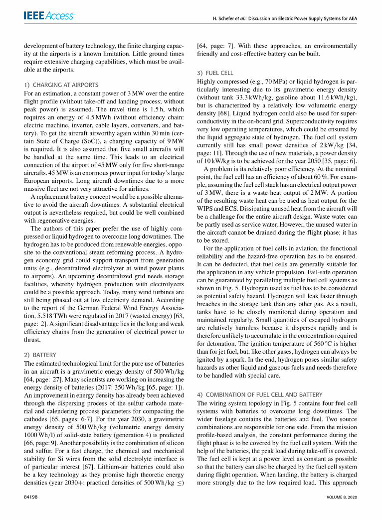
Section VII-A2 deals with the issue of high slew rates andthe resulting Electromagnetic Interference (EMI). A trade-off has to be found between switching speed (losses in thesemiconductor and cooling effort / minimizing passive com-ponents) and the EMC (filter efforts and shielding) of theDC/DC converters.
A converter design might have parasitic ground capaci-tances, which can lead to problems in EMC. For example,a semiconductor module can have a large parasitic capac-itance of the switching node/capacitive node against the
VOLUME 8, 2020 84203
H. Schefer et al.: Discussion on Electric Power Supply Systems for AEA
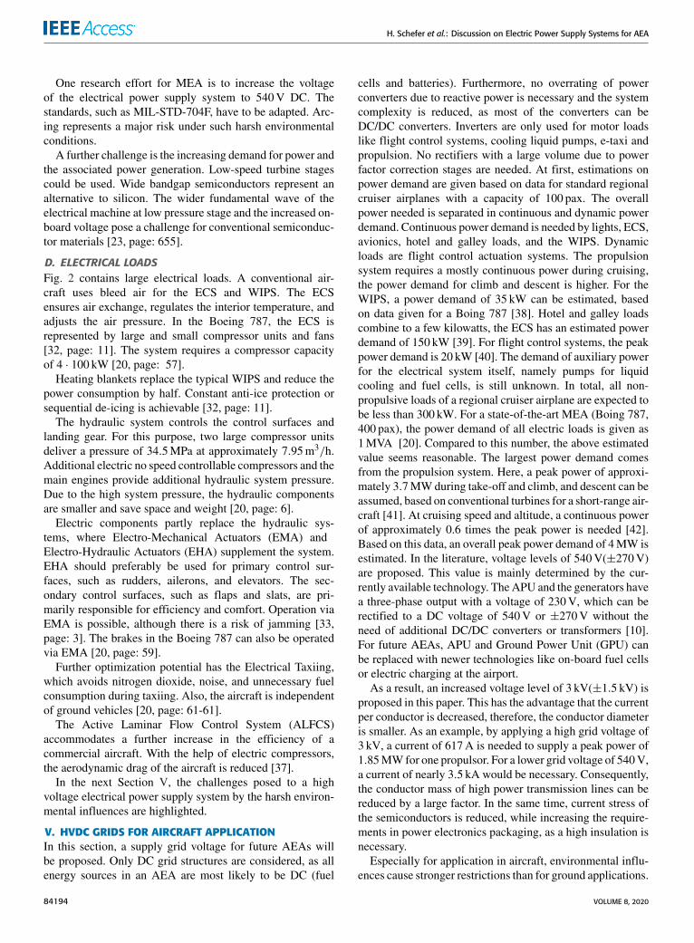
FIGURE 7. Interleaved step-up converter.
backside of the Direct Copper Bonding (DCB) or a largeparasitic capacitance against its base plate.
Furthermore, all components must be designed to be asfault-tolerant (sum of all catastrophic failures of aircraft:FIT: 1 · 10−7) and reliable as possible [34, pages: 6-8]. Thedesign of the converter from passive and active componentsis very challenging under the influence of the requirementsand conditions mentioned above.
1) NON-ISOLATED CONVERTERSAnon-isolated topology could be used to integrate the sourcesinto the electrical power supply system. In publications [69]and [103] on a MEA and a fuel cell-powered small electricaircraft, step-up converters are used. The converter for thebattery has to be bidirectional to enable charging and dis-charging, while the converter connecting the fuel cell can beunidirectional [69], [103].
Fig. 7 shows a step-up converter that can be further opti-mized by interleaving, synchronous rectification, and cou-pled inductors. For maximum efficiency of this converter,the input voltage should be as close as possible to the outputvoltage. This requirement affects the stack level of the batteryand the fuel cell. The converter is characterized above allby a small number of semiconductors; half-bridge modulescan be used. Additionally, good scalability and modularitycan be achieved utilizing interleaving. Also, it is easier tointegrate smaller inductors into an existing cooling concept.Due to the multiphase principle and the use of specific dutycycles, ripple currents of the sources are minimized by can-celling effects.With the aid of the coupled inductors, a furthersize reduction of these is possible [104]. A very powerfulinterleaved step-up converter (100 kW, input voltage 600V,without EMI filter) for automotive applications is presentedin [105]. A power density of 25 kW/kg is achieved with com-mercially available devices. The publication [69, page: 10]presents a DC/DC converter for a MEA with a power densityof 5 kW/kg.
As both rated current and rated voltage are typically lowerfor GaN devices compared to available SiC MOSFET andSi IGBT, the application will be limited to low and mediumpower converters, if not massively parallelized. The usage ofsmaller distributed converter systems requires a suitable gridstructure, but will also lead to a more meshed and redundantsupply grid [106]. As shown in Fig. 5, small Point of Load
FIGURE 8. GaN-based ANPC inverter for an input voltage of 800 V(±400 V).
(PoL) inverters can be used for supplying avionics, hotel andgalley loads from a 800V DC grid. To take into accountthe reduced maximum breakdown voltage due to cosmicradiation, multilevel inverters with five levels need to berealized based on the currently available devices, even for a800V DC grid. As devices with higher voltage rating will beavailable in the future [85, page:5], device count can probablybe reduced. SCC are especially promising. Because of thereduced inductance value and lower device stress, they can bedesigned towards high power density at a high voltage gainand relatively high efficiency, but come with high require-ments in their design and especially EMI aspects [107]. Forhigher power demands, ANPC converters can be used withparalleled output stages (see Fig. 8). While GaN devices prin-cipally allow parallelisation [108], filter design and layoutconsiderations can be simplified by using interleaved GaNhalf bridges. By using a high number of interleaving stages,the system redundancy is increased as well. As a drawback,a high number of inductors is necessary, but typically withless overall weight and volume due to a partial compensationof the ripple currents. For higher blocking voltages, MMCcan be used. Conventional MMC require large module capac-itances and are therefore not suited for weight- and volume-sensitive applications. By using the so-called quasi-two-levelmode, module capacitance can be drastically reduced [109].After detailed study, these systems could find an applicationin future AEA supply grids.
2) ISOLATED CONVERTERSFig. 9 shows a possible topology of an isolated DC/DCconverter. The Dual Active Bridge (DAB) is a bidirectionalisolated converter and conventionally consists of four halfbridges. Due to high switching frequencies, the weight andvolume of the transformer can be reduced. The transformercan achieve a significant voltage amplification ratio, withrespect to the possible stack level. In comparison to the non-isolated converter, there is an increased complexity.
The leakage inductance is mainly responsible for the trans-mittable power. The soft-switching operation of DAB canbe achieved with the resonance of leakage inductance and
84204 VOLUME 8, 2020

H. Schefer et al.: Discussion on Electric Power Supply Systems for AEA
FIGURE 9. Dual active bridge.
drain-source capacitances. The semiconductors on theinverter side (depends on power flow) can operate under ZeroVoltage Switching (ZVS). It allows switching losses to bereduced, less cooling is required, or higher switching frequen-cies are possible. ZVS is determined by the charging processof the drain-source capacitances and the leakage inductance.ZVS cannot be achieved for the entire working range underthe standard Single Phase Shift Modulation (SPS). The lim-itation lies in the magnetically stored energy in the leakageinductance. The semiconductors are in a blocking state overhalf of the duty cycle [110]. Power transmission using phase-shift modulation has advantages concerning cosmic radia-tion. The duty cycle of the semiconductor in this modulationmethod is a maximum of 50%. An optimized control strategyof DAB is the Expand Phase Shift Modulation (EPS), whichincreases the operating range of the ZVS and minimizescirculating currents. Triple Phase Shift Modulation (TPS) hasthree degrees of control, extends the ZVS range to no load,reduces RMS currents and peak currents, and minimizes thetransformer. Another option is a multiphase system [111].
The publication [112] presents a 100 kW isolated DC/DCconverter for renewable energies with a power density of1.2 kW/kg (air-cooled, not gravimetric or volumetric power-dense optimized).
The switching frequency of the DAB can be furtherincreased with a resonant tank consisting of a capacitance andan inductance on each side. It is also known as the CLLCconverter. The variable switching frequency between tworesonant poles allows the output voltage to be adjusted. Zerocurrent switching is available on the rectifying side. A dis-advantage in contrast to DAB is the low bidirectional trans-mission speed [111]. One challenge of the CLLC converteris synchronous rectification [113]. For an accurate standardFundamental Harmonic Analysis (FHA), the highly voltage-dependent output capacitances of semiconductors have to betaken into account. The output capacitance of many semi-conductors changes during the switching process. Further-more, no loss calculation is possible with the standard FHAmethodology, but a loss calculation is essential for a power-dense design of the converter. Publication [114] enables a lossevaluation in the time domain. The time domain enables aloss consideration to be carried out in the same way as for
FIGURE 10. Operation strategy for a reliable AEA system.
FIGURE 11. Possible services provided by the protective devices invarious failure scenarios.
designs of other converter types. In addition, it is challengingto handle various input and output voltages.
VIII. TECHNOLOGIES FOR CIRCUIT BREAKERS FOR AEAWithin the aircraft proposal, Fig. 5, switching operations haveto be performed to connect and disconnect parts of the elec-trical power supply system in the event of occurring failures.In this section, the safety component Circuit Breaker (CB), itsneed and function will be discussed. Subsequently, differentconcepts will be compared to determine an optimal solu-tion for the technical requirements in AEA. Then differenttechnologies for this solution will be discussed and assessedregarding the special requirements. Furthermore, the environ-mental influences on the components will be outlined.
A. HIGH VOLTAGE SWITCH REQUIREMENTS IN AN AEATo reduce the losses in the wiring harness and the weightof the distribution equipment, higher voltages above the lowvoltage level are needed, Section V. This leads to differentequipment in the aircraft which is basically known from thehigh voltage technique.
The operation strategy and possible failure scenarios of theEuropean Plan for Aviation Safety EPAS define the require-ments concerning future circuit breakers.
On the one hand, the operation strategy of the EPAS hasto control and ensure multiple values and system parameters,as can be seen in Fig. 10.
Hence, future circuit breakers must provide a low on-stateresistance to increase the efficiency. Furthermore, for theinclusion into the operation strategy, they have to be remotlyswitchable by a control unit or the staff.
On the other hand, all possible failure scenarios have to berecognized, they lead to additional requirements concerningfuture switches. Thus, multiple factors have to be consideredwithin a failure assessment, Fig. 11:
VOLUME 8, 2020 84205

H. Schefer et al.: Discussion on Electric Power Supply Systems for AEA
Generally, circuit breakers within an aircraft have differenttasks to fulfill, the first priority of the operation strategy is toensure a reliable energy distribution during the whole oper-ating time by controlling the power flow. The most challeng-ing operation is a switching operation during an occurringshort-circuit failure which has to be fullfilled by the circuitbreaker. For nominal switching operations, an integration intoan intelligent control unit is recommended to enhance itsfunctionality. Furthermore, a fail-safe mode of the circuitbreaker is needed to exclude the operation of a damagedbreaker by ensuring a full galvanic separation.
However, circuit breakers are available for DC currents atthis voltage level but they do not meet the requirements interms of weight, volume and especially environmental con-ditions (example: gravimetric power density of 115 kW/kg,for a 3 kV with 800A molded circuit breaker for railwayapplications [115]). Thus, a research and development pro-cess for a functional aircraft circuit breaker is needed. Themain parameters for this process are:
• Short-circuit current• Inductive or capacitive behavior of the energy distribu-tion grid
• Nominal current of the energy distribution grid• Weight and volume• Voltage level• Environmental conditions
The high power requirements of the aircraft during climbmake the usage of energy storage systems with high shortcircuit power unavoidable. This has to be considered duringshort-circuit and nominal current calculations. Furthermore,the cable design and routing will influence the compleximpedance of the wiring harness which has to be consideredin the failure calculation as well. The circuit breakers have tobe weight- and volume-optimized for a reasonable use on anaircraft. With an increased grid voltage, the clearing distancesof the circuit breaker have to be adjusted to meet the environ-mental conditions regarding altitude and temperature [116].Additional parameters for the development and design are:
• Number of switching operations• Contact- or on-state resistance• Explosion protection• Possible galvanic isolation• Switching time• EMC resistance
The number of switching operations which should be per-formed by the circuit breaker (nominal and short circuit)has to be defined. It is recommended that nominal switchingoperations should exceed 10,000 to lower the need for main-tenance during the whole lifetime of the aircraft. To reduceweight of the circuit breaker, it may be possible to reducethe nominal operations, but also with increasing wear. Suchcircuit breakers have to be repetitive changed during morefrequent maintenance periods. The number of operations forshort circuit currents should exceed three operations to pro-vide an additionally safety margin [117]. Short-circuits may
only occur under extreme conditions during emergencies.After such an extreme condition- a mandatory check andmaintenance of the safety equipment should include a checkand a potentially change of the circuit breaker.
Contact- or on-state resistance have to be as small aspossible to reduce the losses of the circuit breakers and toestablish an overall energy-efficient system. Furthermore,the reduction of these losses prevents unacceptable warmingof the circuit breaker due to resistive losses.
Additionally, it may occur that components suited forapplication in explosion-protected areas have to be installed.This may be necessary near fuel or hydrogen supply to avoiddangerous scenarios. Hot-spots and electrical discharges areexpected to enhance the risk of an explosion. Therefore,the circuit breaker should be specially developed to avoidan enhanced risk. However, a systematic assessment of thepotential ignition sources is in any case necessary.
A galvanic separation of the contacts is needed in all highvoltage grids, [118]. It is required to ensure the safety of crewand technicians during maintenance intervals.
The switching time has an influence on the possible short-circuit current, [119]. To reduce the occurring short-circuitcurrent, the detection and the interruption has to be optimized.A fast switching process will reduce the stress within thedistribution grid.
Finally, a circuit breaker which is not affected by electro-magnetic interference during operation is mandatory [120].Interference by inverters and atmospheric influences willoccur during operation and is not allowed to affect the cir-cuit breaker under all circumstances. Therefore, the circuitbreaker has to be resistant against EMI. During its devel-opment process, it is inevitable to respect newest technicalrequirements regarding EMC optimization.
Depending on the topology of the energy distribution grid,a suitable failure detection hardware and software has tocoordinate and control the switches, as proposed in [121]. Thedetection algorithm has to detect, characterize and localizethe failure. With this information, a selective switching oper-ation has to be triggered. Uncommon failures, which lead toblinding [122], [123] or tripping of multiple switches [124]of conventional circuit breakers, have to be avoided throughthis algorithm. This coordinated switching is of particularimportance for the safe operation of the energy distributiongrid and leads to the smallest possible interference of theaircraft. Actual control mechanisms limit the efficiency ofthe system. No suitable protection ultimately leads to higherweight in the equipment in order to establish the highestpossible safety requirements which should be applied forenergy distribution in an AEA.
B. POSSIBLE CIRCUIT BREAKER TECHNOLOGIESIn general, different circuit breaker concepts are applica-ble in an energy distribution grid of an aircraft. However,the abovementioned requirements should be discussed fordifferent concepts in order to propose the best suitable circuit
84206 VOLUME 8, 2020

H. Schefer et al.: Discussion on Electric Power Supply Systems for AEA
FIGURE 12. Examples for circuit breaker: (1) vacuum interrupter [125], (2)Solid state circuit breaker [126], (3) circuit breaker with arc chamber [115],(4) sketch of hybrid circuit breaker [127], (5) high voltage fuse [128].
breaker for this new application considering the high volt-ages, Fig. 12.
1) VACUUM INTERRUPTERTypical circuit breakers in the medium voltage level arevacuum interrupters. Considering the special environmentalconditions in an aircraft, they provide an excellent dielectricstrength which is not affected by the reduced pressure in alloperation heights. Furthermore, through hermetic encapsula-tion and low contact resistances in the area of several µ�,they provide advantages considering the explosion protectionassessment of the system. Currents up to 63.5 kA at several10 kV are switchable providing a galvanic separation. How-ever, direct currents are not yet interruptible due to the miss-ing repetitive current zero crossing. Additionally, the weightof these circuit breakers is enhanced due to the motor driveswhich are necessary to move the contact in the vacuum.However, for AC distribution systems with high voltages,this may be a technology which should be considered in aprotection system assessment.
2) ELECTRONIC CIRCUIT BREAKERSolid State Circuit Breakers (SSCB) or Solid State PowerControllers (SSPC) are the state of the art for energy dis-tribution in aircrafts up to DC voltages of 270V [120].DC and AC voltages of variable frequencies are controllable
by these devices. Higher voltage levels are not available atthe moment, however, in the near future, SSCB could bedeveloped using new types of power semiconductors withhigher blocking voltages. The sizing of the SSCB is in prin-cipal depending on the short-circuit calculation with respectto inductive loads and nominal current flow. Additionally tothe power semiconductor and the control unit, an overvoltageprotection is needed within the SSCB. For the further SSCBdevelopment, the occurring inductive loads should be consid-ered as one main sizing parameter.
However, using this principle, no galvanic isolation is pro-videdwhich is a disadvantage considering the personal safety.Furthermore, with the power semiconductors in the main pathof the SSCB, the on-state resistance is increased comparedto all mechanical circuit breakers. The increase compared tomechanical circuit breaker depends on the semiconductors.In a first approach an increase of three orders of magnitudeis a first permissible generalisation. This leads to comparablehigh losses and the possible formation of hotspots on the cir-cuit board, especially considering the high nominal currentsduring climb. A suitable cooling design is necessary whichincreases the weight of the SSCB significantly.
Principally, the SSCB is a low risk considering explosionprotection, however, hotspots and surface charges still haveto be considered in the risk assessment.
3) CIRCUIT BREAKER WITH ARC CHAMBERCircuit breakers with arc chambers are available for differentapplications (for example, electrical vehicles, manufacturingfacilities or rail applications). Applications for several MWswitching capability are available and state of the art. The cir-cuit breaker can securely provide this high switching powereven with high voltages up to 3 kV, [115].
During the breaking process, a controlled arc is ignitedand driven into the arc chamber (consisting of arc splitterblades or ceramic blades). The arc voltage rises above gridvoltage level. As a result, the arc is extinguished withinseveral milliseconds. Bidirectional DC as well as AC currentscan be forced safely to zero, applying this principle. How-ever, mechanical complex geometries are necessary whichincreases the weight of this circuit breaker technology. Fur-thermore, the weight increases even more for AEA appli-cation because of the special conditions in aircraft [116].Here, the creeping and air distances of the contacts haveto be increased due to the lower air pressure. The contactresistance can be kept low within several µ�, resulting inonly few electrical losses. However, the explosion protectionof the system has to be considered exhaustively because of theappearance of hot plasma and gases within the arc chamberduring arc quenching. Depending on the location of opera-tion, a capsulation of the circuit breaker can be necessary.In most cases, CB with arc chambers establishes a galvanicseparation. The number of operations for nominal currents islimited to several thousand because of occurring erosion atthe switching contacts.
VOLUME 8, 2020 84207

H. Schefer et al.: Discussion on Electric Power Supply Systems for AEA
Additionally, it shall be mentioned that circuit breakerswith reduced weight are in principal possible and able tocontrol high arc voltages but at the expense of switching oper-ations due to the use of forced vaporizing polymers, [129].
4) HYBRID CIRCUIT BREAKERA combination of an arc-based circuit breaker and powersemiconductor has been described in many research anddevelopment projects in the last years [119], [127]. This typeof switch unites advantages of both switching principles withreduced weight and volume requirements. Cooling systems toprotect the power electronic equipment are not necessary butan overvoltage protection is mandatory. The cooling can beavoided, since the current during on-state is conducted by theelectrical contacts with their low forward resistance. Com-plex and heavy arc chambers are avoided since the switch-off process is carried out by the power electronic part ofthe hybrid circuit breaker. The occurring contact erosion isstrongly reduced in contrast to other switching principles; as aresult, the service life of a hybrid switch is strongly extended.
Hybrid circuit breakers are realizable in differenttopologies, [119], [127], [130]–[132]. Using this switchingprinciple leads to several different possibilities for galvanicseparation, current capacity, dielectric strength, weight andvolume.
5) FUSESIn principal, fuses provide a good switching performancewith low volume andweight of the components. Furthermore,there are several possibilities to trigger fuses remotely, forexample, by a failure detection algorithm [122]. However,the missing possibility to switch-on is in case of emergencyin an aircraft is substantial.
6) CONCLUSION OF CIRCUIT BREAKER TECHNOLOGIESThe result of to the discussed circuit breaker principles havebeen summarized in Table 2. In this table, parameters whichare beneficial for an application of this circuit breaker withinan AEA are marked with ‘‘+’’ and even better with ‘‘++’’.Non-beneficial, but no parameters which exclude this tech-nology, are marked with ‘‘o’’. Finally, parameters which pre-vent the application of this technology within an AEA aremarked with ‘‘−’’.
The hybrid switch theoretically provides an acceptabletrade-off for the regarded parameters. Some parameters hereare dependent on the chosen circuit breaker topology as dis-cussed below. However, the table is concluded for all switchesas a first rough estimation, thus no actual circuit breaker in theassumed area of operation and for this application is availableat the moment. For the hybrid switch, the values in the tablewere extrapolated, and assuming [127], they were measuredfor voltages up to 475V, a time constant up to 3 ms andcurrents of up to 200A. These values are derived from amodel switch for scientific purposes and can be increasedscientifically in industry products. However, voltages over3 kV will need a different design lack of discrete IGBTs, thus
TABLE 2. Possible circuit breaker for AEAs.
a reliable assumption for this application is not possible at themoment.
C. HYBRID CIRCUIT BREAKER TOPOLOGIESFor further consideration, the hybrid switch will be discussedin terms of possible topologies. Different topologies canaffect some decision criteria as marked in Table 2. At themoment, different possible topologies are under develop-ment. The different approaches can be sub-classified into:
1) Arc-free circuit breaker2) Circuit breaker with reduced arc occurrence3) Circuit breaker with optimized arc chamber
Every topology provides its own advantages and disadvan-tages during its operation within an AEA, which will bediscussed below. However, every topology can be realized forbi-directional switching.
1) TOPOLOGYAskan published in [132] an approach for circuit breakers upto 125A at a voltage level of 380V. This circuit breaker issuitable for suppressing short-circuit currents up to 20 kA.The possible maximum time constant for the switching pro-cess is not mentioned in this publication. The principal topol-ogy consists of, Fig. 13:
• Mechanical switches (MS)• Auxiliary power electronic switches in the main path(APES)
• Power electronic switches in the switching part of thehybrid topology (MPES)
In the main branch of the switch topology, the MOSFET ofthe APES is chosen with low on-state resistance. The forwardlosses are mentioned with several 10W, linearl extrapolated
84208 VOLUME 8, 2020

H. Schefer et al.: Discussion on Electric Power Supply Systems for AEA
FIGURE 13. Hybrid switch topology 1.
FIGURE 14. Hybrid switch topology 2.
to the assumed area of operation, leading to forward losses ofseveral hundred watts.
During the switching process, the current commutates fromthe main branch to the switching branch with the MPES.This is where the switching process with the main powerelectronic takes place. After current zero, MS2 can be openedto achieve a galvanically separated state of the circuit breaker.One important advantage of this topology is the theoreticallycompletely arc-free switching process by the APES in themain path. The explosion protection of this switching prin-ciple is superior for the regarded hybrid switch topologies,however, the MOSFET provides a significant barrier layercapacity. This will result in a large changing current whenthe mechanical switch is closed, which may cause a pre-strike arc. This has to be considered in an explosion protectionassessment.
A disadvantage of this topology is that for the operationof the driver circuit, an external voltage supply for the APESand the MPES is necessary. Here redundancy for the use inan aircraft has to be considered in the development process.Furthermore, a failure of one part of the power electronicequipment leads to a complete failure of the whole devicewhere the device will remain conductive; no fail-safe state ispossible.
2) TOPOLOGYTopology 2) of a hybrid switch is given in Fig. 14 and is pub-lished by Bösche et al. [127]. This approach was successfullydemonstrated for voltages up to 475 V and currents of 200 Awith a time constant of 3 ms. Topology 2) consists of:• Mechanical switch in the main branch• Power electronics for the switching process• Mechanical switch for galvanic separation in the switch-ing branch
FIGURE 15. Hybrid switch topology 3.
In this topology, the Power Electronics (PE) is in parallelconnection to a mechanical switch. During a switching pro-cess,MS1 opens and draws an arc.With an occurring arc volt-age, the PE drive switches the PE on. The current commutatesfrom the main branch onto the power electronics. The arcdeionizes within a known time period [133]. With a sufficientdielectric strength of Mechanical Switch MS1, the powerelectronics is switched off. The current is suppressed to zeroby a varistor within PE. For the following galvanic separationswitch MS2 has to be opened afterwards.
An advantage of this topology is the simple construction ofthe device. With the intentionally arc formation the voltagesupply for the driver circuit can be used from the arc voltageitself [127], [134]. Furthermore, the on-state resistance issmall, thus only one mechanical contact with typical con-tact resistances of several micro ohms is conducting duringswitch-on.
A disadvantage of this topology is that the explosion pro-tection is reduced, as an arc is necessary for the driver circuit.Furthermore, the contact erosion is not completely avoidedthrough the arc in MS1. But in contrast to typical circuitbreakers with arc chambers, the erosion is strongly decreased.Like Fig. 13, this switch has no fail safe, thus with a failurein the power electronics a switch-off is not possible anymore.
3) TOPOLOGYThe robustness possibility for a hybrid switch is givenin Fig. 15 and consists of:• Mechanical switch in the main branch• Power electronics for the switching process• Circuit breaker for fail-safeThe functionality of this switching topology is comparable
to Fig. 14. Thus, after switch-off through the power electron-ics, a special designed circuit breaker establishes the galvanicseparation, [127]. This provides the advantage that in thecase of a failure of the power electronics, the circuit breakerwill establish a fail-safe state. In contrast to conventionalcircuit breakers with arc chamber, this circuit breaker can bedistinctly lighter, so that only one switching operation underload is necessary.
As in Fig. 14, the arc voltage can directly supply the driver.Disadvantages are the slightly increased weight, and the
doubled contact resistance, so that two switches in seriesconnection are necessary.
However, every topology and switching technology has itsown superior advantages. An assessment of the topology for
VOLUME 8, 2020 84209

H. Schefer et al.: Discussion on Electric Power Supply Systems for AEA
the given area of operation within the system is necessary.For a highly trustworthy operation of the power distribution,topology 3) is recommended. But this component has to beincluded into the maintenance periods. If an additional explo-sion protection is needed, the use of a completely moldedhybrid switch should be considered.
IX. WIRING HARNESSCurrently, a direct current distribution with voltage levelsup to ±270V is used in MEAs [135]–[137]. To enable atechnology change to AEAs an increase of the supply voltageis necessary in order to reduce the weight of the electricalpower transmission system, [20], [138]. With the actual sup-ply voltage, the equipment weight of the energy supply is toohigh for an application in the aviation, due to the occurringhigh nominal currents for the overall electrical demand of anAEA, e.g. Section VI.The increase of the supply voltage up to several kilovolts
is needed to achieve a weight-optimized distribution grid[139], [140]. The use of a higher supply voltage providesnew opportunities considering electrical aircraft components,however, serious challenges have to be carefully solved inseveral preceding research projects.
On the one hand, new grid technologies are under devel-opment and have to be further developed and analyzed, [8],[140], [141]. Among others, load flow calculations, failurescenario assessment and failure current calculations have sig-nificant influence on these grid technologies. The grid designwith its components has the significance of a key technologyfor the whole AEA.
On the other hand, distribution components, switchgear(Section VIII) and power transmission lines, have to bechanged drastically to meet the requirements for the oper-ation in the aviation [116], [142]. The main challenges forthe transmission lines to make higher voltages available areamong others:
• Arcing• Partial discharge (Partial Discharge (PD))• Surface charges• Thermal management• Conductor material
Arcing is a major risk during the operation of an air-craft [143], [144]. The risk and the potential damageincreased significantly with the use of a DC supply volt-age [145]. Publications point out that the use of aluminumconductors could increase the possible damage of an occur-ring arcing [143]. Thus, an appropriate choice of insulationmaterial of the cables is needed [145], [146]. Furthermore,switchgears with fault arc detection and sufficient switchingcapability are essential for a safe operation of an AEA [147].Especially for meshed DC-grids, further research is needed toensure a safe operation [148]. The occurrence of PD in DC-systems is a known issue [149], [150]. The occurrence of PDwithin the wiring harness has to be excluded to increase thereliability of the insulation of the distribution cables and to
FIGURE 16. Possible cable structure for high voltage distribution for AEA.
minimize the risk of arcing [151]. However, due to the wiringpraxis in electrical aircraft electrical field enhancements canbe the consequence and lead to PD [152], [153]. Further-more, high operating temperatures due to high distributioncurrents could lead to a faster aging of the cables and haveto be tested in PD-tests before the cable design is selected[149], [154], [155]. Solutions to eliminate PDs could bedeveloped in future research projects, like the use of screenedcables [156] and new insulation materials which providebetter PD resistance sheathes [157]. Surface charges of dif-ferent insulation materials could lead to electrostatic dis-charges. Discharges with comparably low energy could ignitehydrogen which is a possible energy source of an AEA, e.g.Section VI.With regard to the lower ignition propensity a riskassessment with regard to explosion protection is needed forthe use of any distribution cable within an AEA powered bya fuel cell.
The dimensioning of power cables is highly dependenton the temperature behaviour of the cable [158]. For thedevelopment of new types of cables especially designed forhigh power transmission on board of an aircraft, there aresome physical limits regarding the temperature behaviour.In contrast to current cables, the calculation under full load isnecessary to provide weight-optimized components. Currentdimensioning regulations only calculate with partial load ofthe cables [142] Chapter 3.8.8.1.1. Physical limitations incable development are:• A strongly limited convection due to the lower air pres-sure (depending on the flight altitude)
• Heat conduction only at the connectors• Possibly limited radiation losses due to thermal stabilityof insulation materials
The selection of the conductor material is discussed andassumed in several publications [139], [159]. For high trans-mission, powers aluminum is mainly preferred as conductormaterial due to the ratio of weight to power transmis-sion [139]. However, apart from the fact that the calculationis based on the design for the traditional power transmissionon board [139] and not on the not yet defined special caseHVDC, there are restrictions by the Federal Aviation Admin-istration (FAA) which limit the use of aluminum as conductormaterial [142]. Among others, these restrictions are:• No approval of aluminum cables on engines• No mounting on areas with severe vibrations
A principal cable structure is shown in Fig. 16:Here, conductor shield and insulation screen fulfill the
tasks of a field grading. The insulation material could be
84210 VOLUME 8, 2020

H. Schefer et al.: Discussion on Electric Power Supply Systems for AEA
classic materials like PTFE, ETFE, PI [145], maybe evenmaterials adapted from HVDC transmission cables likeXLPE [157] have to be considered, taking into accountthe abovementioned boundary conditions. The jacket servesas mechanical protection and consists of plastic materialslike PVC.
In conclusion, there are many research projects ongoingwhich will enable us to design better and more reliablehigh-power transmission cables in the future. However, moreresearch efforts especially for the aviation are needed totake the transmission voltage and transmission power to anew feasible level. Interesting studies with high potential arecurrently being carried out. They discuss and suggest differ-ent new technology solutions like superconductivity [160],selective protection of DC grids [121] and many more.
X. CONCLUSION AND OUTLOOKThe air transportation sector today produces a large amountof CO2 emissions. Additionally, fossil energy resources arelimited. Like in transportation on rail and on the road, newconcepts are needed for air transportation. Approaches forsustainable air transport are based on synthetic fuels or elec-trochemical sources followed by consequent electrification.The first step towards more electrification areMEAs like Air-bus A 380 and Boeing 787-8 Dreamliner with approximately1MVA electrical power at maximum. Here, the electricalpower is generated by four generators of the conventionalmain engines. For future AEAs, hydrogen and batteries aresuggested as the only energy sources which deliver electricalenergy to an electrical power system of an aircraft.
The goal of this publication is the discussion about futureelectrical power systems for an AEA with a maximum powerdemand of 3.7MW for short-range flights. Important elec-trical components in the power system are power converters,cables, and safety switches. Highest power density for all ofthese components is a must. Due to the high energy demand,the conventional AC distribution system has to be replaced bya DC system with an increased voltage level.
Fast-switching wide bandgap semiconductors, based onSiC and GaN, are a promising approach to follow the dis-cussed path. Assuming two-level power electronic converters,6.5 kV SiC semiconductors seem to be a viable solution tooperate at a DC voltage of 3 kV(±1.5 kV), while also allow-ing for a high switching frequency and therefore size reduc-tion of passive components. Reliability and safety are stillopen issues. Gate oxide reliability and short-circuit capabilityare still under critical discussion. For high altitudes, also cos-mic radiation has to be considered. Decreased reliability dueto cosmic radiation is currently examined. However, espe-cially wide bandgap devices promise an increased rugged-ness to radiation compared with conventional Si switches.The demand for high voltage and high switching frequencydevices for the application in AEA could further drive SiCsemiconductor development and use. GaN devices are com-mercially available today with lower voltage ratings up to650V. A strong blocking voltage increase seems unlikely
during the next years. For the application in a 3 kV HVDCpower system of an AEA, multilevel topologies like ANPCor MMC are needed. The higher number of used switchesleads to increased complexity. Therefore, the application ofGaN devices is most likely in smaller PoL andmedium powerconverters far below 1MW power. The reduction of passivecomponent size is possible due to higher switching frequencybut has to be balanced against EMI issues. The reliability ofGaN is completely under investigation.
The need of a galvanic isolation in power electronic topolo-gies is under discussion. At a first glance, non-isolatedtopologies like synchronous bidirectional converters promiselower weight. If the output voltage of the sources is in therange of the HVDC voltage level of 3 kV (±1.5 kV), thisconverter type delivers high efficiency. Due to the absenceof a transformer, the effort for EMI filtering will increase incomparison to isolated converters. The EMI filtering com-plexity depends on several factors like switching frequency,modulation strategy, design of the circuit, magnetic compo-nent and cooling path. Investigations are required to get aconcrete design.
The use of circuit breakers in an AEA is discussed withseveral different types which are rated in conclusion. Theselection process of CBs is rather complex and has toconsider different requirements like environmental condi-tions and aircraft standards, they influence the componentparameters, such as short-circuit current and supply voltage.For a highly reliable operation of the power distributionsystem, a hybrid circuit breaker is a viable alternative tothe current SSCBs, as they provide promising capabilitiesregarding galvanic isolation, gravimetric power density andsupply voltage. The hybrid circuit breaker could be a keycomponent to enable fully electrified aviation. The hybridCB provides a good trade-off for the main requirements asgiven in Table 2. However, considering the current researchand development effort, the area of operation of these CBwill increase significantly in the next years. Furthermore,for the operation of hybrid switches in an AEA, severalopen questions have to be answered: dielectric restorationof the arc within the CB, the behavior of the dielectricstrength within the CB, EMC, influence of cosmic radiationon the power semiconductors, thermal management in anenvironment of reduced air pressure and explosion protection.Additionally, the CB has to be included in the maintenanceperiods.
Concerning the wiring harness, many questions remainunanswered. Several important design parameters like alti-tude, grid structure, voltage level and nominal current levelare unknown. Also, the behavior of the materials has tobe investigated for the proposed cables, concerning arcing,partial discharge, surface charges, thermal management andconductor materials.
All the issues discussed will have to be examined in detailin the coming years. Many research efforts are currently inprogress, and a promising solution should be available withinthe required time frame.
VOLUME 8, 2020 84211

H. Schefer et al.: Discussion on Electric Power Supply Systems for AEA
REFERENCES[1] Flightpath 2050: Europe’s Vision for Aviation; Maintaining Global Lead-
ership and Serving Society’s Needs; Report of the High-Level Group onAviation Research, Eur. Commission, Publications Office Eur. Union,Luxembourg, U.K., 2011.
[2] S. Kelly and D. K. Kumar. Jet Fuel Costs Could Rise From New Rulesto Improve Air Quality. Accessed: Nov. 11, 2019. [Online]. Available:https://uk.reuters.com/article/shipping-imo-jet-fuel/jet-fuel-costs-could-rise-from-new-rules-to-improve-air-quality-idUKL2N22X1N9
[3] International Air Transport Association. (2019). Fuel FactSheet. [Online]. Available: https://www.iata.org/contentassets/25e5377cf53c4e48bbaa49d252f3ab03/fact-sheet-fuel.pdf
[4] P. Wheeler and S. Bozhko, ‘‘The more electric aircraft: Technology andchallenges.,’’ IEEE Electrific. Mag., vol. 2, no. 4, pp. 6–12, Dec. 2014.
[5] R. I. Jones, ‘‘The more electric aircraft: The past and the future?’’ inProc. IEE Colloquium. Electr. Mach. Syst. Electric Aircr., London, UK,Nov. 1999, p. 1.
[6] J.-K. Mueller, A. Bensmann, B. Bensmann, T. Fischer,T. Kadyk, G. Narjes, F. Kauth, B. Ponick, J. Seume, U. Krewer,R. Hanke-Rauschenbach, and A. Mertens, ‘‘Design considerations forthe electrical power supply of future civil aircraft with active high-liftsystems,’’ Energies, vol. 11, no. 1, p. 179, 2018.
[7] M. Tariq, A. I. Maswood, C. J. Gajanayake, and A. K. Gupta, ‘‘Aircraftbatteries: Current trend towards more electric aircraft,’’ IET Electr. Syst.Transp., vol. 7, no. 2, pp. 93–103, Jun. 2017.
[8] A. Lucken, J. Brombach, and D. Schulz, ‘‘Design and protection of a highvoltage DC onboard grid with integrated fuel cell system on more electricaircraft,’’ in Proc. Electr. Syst. Aircr., Railway Ship Propuls., Bologna,Italy, Oct. 2010, pp. 1–6.
[9] T. Kadyk, C.Winnefeld, R. Hanke-Rauschenbach, and U. Krewer, ‘‘Anal-ysis and design of fuel cell systems for aviation,’’ Energies, vol. 11, no. 2,p. 375, 2018.
[10] J. Brombach, A. Lucken, B. Nya, M. Johannsen, and D. Schulz, ‘‘Com-parison of different electrical HVDC-architectures for aircraft applica-tion,’’ in Proc. Electr. Syst. Aircr., Railway Ship Propuls., Bologna, Italy,Oct. 2012, pp. 1–6.
[11] C. Salb, S. Gül, C. Cuntz, Y. Monschauer, and J. Weishäupl, Klimaschutzin Zahlen: Fakten, Trends und Impulse Deutscher Klimapolitik.Frankfurt, Germany: BMU, Druck-und Verlagshaus Zarbock GmbH &Co. KG, 2018. Accessed: Oct. 15, 2019. [Online]. Available: https://www.bmu.de/fileadmin/Daten_BMU/Pools/Broschueren/klimaschutz_in_zahlen_2018_bf.pdf
[12] German Static Federal Office. Kohlendioxidemissionen Im VerkehrGegenüber 1990 Gestiegen. Accessed: Oct. 15, 2019. [Online].Available: https://www.destatis.de/Europa/DE/Thema/Umwelt-Energie/CO2_Sektoren.html
[13] European Parliament. CO2 Emissions From Cars: Facts andFigures. Accessed: Oct. 15, 2019. [Online]. Available: https://www.europarl.europa.eu/news/en/headlines/society/20190313STO31218/co2-emissons-from-cars-facts-and-figures-infographics
[14] Air Transport Action Group. Facts and Figures. Accessed: Oct. 15, 2019.[Online]. Available: https://www.atag.org/facts-figures.html
[15] International Air Transport Association. (2018). IATA Forecast Predicts8.2 billion Air Travelers in 2037. Accessed: Oct. 15, 2019. [Online].Available: https://www.iata.org/pressroom/pr/Pages/2018-10-24-02.aspx
[16] German Association for the Environment and Nature Conserva-tion. Die Wahren Kosten Des Fliegens: Klimakiller Luftverkehr.Accessed: Oct. 15, 2019. [Online]. Available: https://www.bund.net/themen/mobilitaet/infrastruktur/luftverkehr/co2-emissionen/?wc21726
[17] U.S. Energy Information Administratio. Annual Energy Outlook2019. Accessed: Oct. 15, 2019. [Online]. Available: https://www.eia.gov/outlooks/aeo/pdf/aeo2019.pdf
[18] United Nations. (2015). Paris Agreement. Accessed: Oct. 15, 2019.[Online]. Available: https://unfccc.int/process-and-meetings/the-paris-agreement/the-paris-agreement
[19] Airbus. A380: Unique Passenger Experience. Accessed: Oct. 15, 2019.[Online]. Available: https://www.airbus.com/aircraft/passenger-aircraft/a380.html
[20] B. Sarlioglu and C. T. Morris, ‘‘More electric aircraft: Review, chal-lenges, and opportunities for commercial transport aircraft,’’ IEEE Trans.Transport. Electrific., vol. 1, no. 1, pp. 54–64, Jun. 2015, doi: 10.1109/TTE.2015.2426499.
[21] Boeing. Boeing 787, Dreamliner. Accessed: Oct. 15, 2019. [Online].Available: http://www.boeing.com/commercial/787/
[22] Airbus. E-Fan X, A Giant Leap Towards Zero-Emission Flight. Accessed:Oct. 15, 2019. [Online]. Available: https://www.airbus.com/innovation/future-technology/electric-flight/e-fan-x.html#objective
[23] V. Madonna, P. Giangrande, and M. Galea, ‘‘Electrical power gener-ation in aircraft: Review, challenges, and opportunities,’’ IEEE Trans.Transport. Electrific., vol. 4, no. 3, pp. 646–659, Sep. 2018, doi: 10.1109/TTE.2018.2834142.
[24] Rolls Royce. The E-Fan X Programme. Accessed:Oct. 15, 2019. [Online]. Available: https://www.rolls-royce.com/media/our-stories/insights/2018/paul-stein-talks-about-e-fan-x.aspx
[25] J. Welstead and J. L. Felder, ‘‘Conceptual design of a single-aisle turbo-electric commercial transport with fuselage boundary layer ingestion,’’in Proc. 54th AIAA Aerosp. Sci. Meeting, Jan. 2016, p. 1027, doi: 10.2514/6.2016-1027.
[26] J. L. Kratz and G. L. Thomas, ‘‘Dynamic analysis of the STARC-ABLpropulsion system,’’ in Proc. AIAA Propuls. Energy Forum, Aug. 2019,p. 4182. [Online]. Available: https://arc.aiaa.org/doi/abs/10.2514/6.2019-4182
[27] K. V. Papathakis, K. J. Kloesel, Y. Lin, S. Clarke, J. J. Ediger,and S. Ginn, ‘‘Design and development of a 200-kW turbo-electricdistributed propulsion testbed,’’ in Proc. 52nd AIAA/SAE/ASEE JointPropuls. Conf. (Propuls. Energy), Jul. 2016, p. 17. [Online]. Available:https://ntrs.nasa.gov/search.jsp?R=20160009765
[28] M.-F. Liou, D. Gronstal, H. J. Kim, andM.-S. Liou, ‘‘Aerodynamic designof the hybrid wing body with nacelle: N3-X propulsion-airframe config-uration,’’ in Proc. 34th AIAA Appl. Aerodyn. Conf., Jun. 2016, p. 3875.[Online]. Available: https://arc.aiaa.org/doi/10.2514/6.2016-3875
[29] M. J. Armstrong, M. Blackwelder, A. Bollman, C. Ross,A. Campbell, C. Jones, and P. Norman, ‘‘Architecture, voltage,and components for a turboelectric distributed propulsion electricgrid,’’ Nat. Aeronaut. Space Admin., Washington, DC, USA, FinalRep. NASA/CR-2015-218440, 2015, p. 270. [Online]. Available:https://ntrs.nasa.gov/archive/nasa/casi.ntrs.nasa.gov/20150014237.pdf
[30] J. J. Berton and W. J. Haller, ‘‘A noise and emissions assess-ment of the N3-X transport,’’ in Proc. 52nd Aerosp. Sci. Meeting,Jan. 2014, pp. 1–22. [Online]. Available: https://ntrs.nasa.gov/archive/nasa/casi.ntrs.nasa.gov/20150014237.pdf
[31] X. Roboam, B. Sareni, and A. Andrade, ‘‘More electricity in the air:Toward optimized electrical networks embedded in more-electrical air-craft,’’ IEEE Ind. Electron. Mag., vol. 6, no. 4, pp. 6–17, Dec. 2012,doi: 10.1109/MIE.2012.2221355.
[32] M. Sinnett, ‘‘787 no-bleed systems: Saving fuel and enhancingoperational efficiencies,’’ Boeing AEROMAGAZINE, A QuarterlyPublication, Seattle, WA, USA, Tech. Rep., 2014. [Online]. Available:http://www.boeing.com/commercial/aeromagazine/articles/qtr_4_07/index.html
[33] P. Wheeler, ‘‘Technology for the more and all electric aircraft of thefuture,’’ in Proc. IEEE Int. Conf. Automatica (ICA-ACCA), Oct. 2016,pp. 1–5, doi: 10.1109/ICA-ACCA.2016.7778519.
[34] A. Lücken, ‘‘Integration von brennstoffzellen in flugzeugbordnetze,’’Ph.D. dissertation, VDE Verlag GMBH, Helmut-Schmidt-Univ.,Hamburg, Germany, 2014.
[35] Z. Dai, L. Wang, and S. Yang, ‘‘Fuel cell based auxiliary powerunit in more electric aircraft,’’ in Proc. IEEE Transp. Electrific.Conf. Expo, Asia–Pacific (ITEC Asia–Pacific), Aug. 2017, pp. 1–6,doi: 10.1109/ITEC-AP.2017.8080851.
[36] S. Wu and Y. Li, ‘‘Fuel cell applications on more electrical aircraft,’’in Proc. 17th Int. Conf. Electr. Mach. Syst. (ICEMS), Oct. 2014,pp. 198–201, doi: 10.1109/ICEMS.2014.7013481.
[37] N. Beck, T. Landa, A. Seitz, L. Boermans, Y. Liu, and R. Radespiel,‘‘Drag reduction by laminar flow control,’’Energies, vol. 11, no. 1, p. 252,Jan. 2018.
[38] O. Meier and D. Scholz. (2010). Estimation of Power Requirements forElectrical De-Icing Systems. [Online]. Available: https://www.fzt.haw-hamburg.de/pers/Scholz/MOZART/MOZART_PUB_DLRK_10-08-31.pdf
[39] J. Herzog, ‘‘Electrification of the environmental control system,’’ inProc. 25th Int. Congr. Aeronaut. Sci., 2006, pp. 1–4. [Online]. Available:http://icas.org/ICAS_ARCHIVE/ICAS2006/PAPERS/344.PDF
[40] D. Eugenio, G. Di Rito, R. Galatolo, and F. Schettini, ‘‘All-electric flightcontrol system and landing gear system models for power assessmentstudies,’’ in Proc. 3AF/CEAS Conf. ‘Greener Aviation, Clean Sky Break-throughs Worldwide Status, Bruxelles, Belgium, 2014.
84212 VOLUME 8, 2020

H. Schefer et al.: Discussion on Electric Power Supply Systems for AEA
[41] Type-CertificateData Sheet: Pratt &Whitney Canada PW150 Series, Eur.Aviation Saf. Agency, Cologne, Germany, 2014.
[42] B. Jux, S. Foitzik, and M. Doppelbauer, ‘‘A standard mission profile forhybrid-electric regional aircraft based on Web flight data,’’ in Proc. IEEEInt. Conf. Power Electron., Drives Energy Syst. (PEDES), Chennai, India,Dec. 2018, pp. 1–6.
[43] Engineering ToolBox, U.S. Standard Atmosphere. Accessed:Nov. 22, 2019. [Online]. Available: https://www.engineeringtoolbox.com/standard-atmosphere-d_604.html
[44] F. Paschen, ‘‘Über die zum Funkenübergang in Luft, Wasserstoffund Kohlensäure bei verschiedenen Drücken erforderliche potentialdif-ferenz,’’ Ann. Phys., vol. 273, no. 5, pp. 69–96, 1889.
[45] NASA Langley Research Center. Nowcast of Atmospheric Ionizing Radi-ation System: Current Dose Rates. Accessed: Feb. 7, 2020. [Online].Available: http://sol.spacenvironment.net/~nairas/Dose_Rates.html
[46] W. Friedberg and K. Copeland, Ionizing Radiation in Earth’s Atmosphereand in Space Near Earth, Civil Aerosp. Med. Inst. Oklahoma City,Washington, DC, USA, May 2011.
[47] B. Tala-Ighil, J.-L. Trolet, H. Gualous, P. Mary, and S. Lefebvre, ‘‘Exper-imental and comparative study of gamma radiation effects on Si-IGBTand SiC-JFET,’’ Microelectron. Rel., vol. 55, nos. 9–10, pp. 1512–1516,Aug. 2015, doi: 10.1016/j.microrel.2015.06.136.
[48] K. Boomer, L. Scheik, and A. Hammoud. Body of Knowledge(BOK): Gallium Nitride (GaN) Power Electronics for SpaceApplications. Accessed: Jul. 7, 2020. [Online]. Available:https://nepp.nasa.gov/workshops/etw2019/talks/0619WED/1300%20-%20GaN%20BOK%20NEPP%20ETW%20Presentation7.pdf
[49] M. Zerarka, P. Austin, A. Bensoussan, F. Morancho, and A. Durier,‘‘TCAD simulation of the single event effects in normally-off GaN tran-sistors after heavy ion radiation,’’ IEEE Trans. Nucl. Sci., vol. 64, no. 8,pp. 2242–2249, Aug. 2017.
[50] A. Y. Polyakov, S. J. Pearton, P. Frenzer, F. Ren, L. Liu, and J. Kim,‘‘Radiation effects in GaN materials and devices,’’ J. Mater. Chem. C,vol. 1, no. 5, pp. 877–887, 2013.
[51] S. J. Pearton, R. Deist, F. Ren, L. Liu, A. Y. Polyakov, and J. Kim,‘‘Review of radiation damage in GaN-based materials and devices,’’J. Vac. Sci. Technol. A, Vac. Surf. Films, vol. 31, no. 5, Sep. 2013,Art. no. 050801.
[52] C. Weiß, ‘‘Höhenstrahlungsresistenz von Silizium-Hochleistungsbauelementen,’’ Ph.D. dissertation, Chair Tech.Electrophys., Technische Univ. München, Munich, Germany, 2015.
[53] Measurement and Reporting of Alpha Particle and Terrestrial CosmicRay-Induced Soft Errors in Semiconductor Devices, document JESD89A,2006.
[54] C. Felgemacher, ‘‘Investigation of reliability aspects of power semi-conductors in photovoltaic central inverters for sunbelt regions,’’ Ph.D.dissertation, Dept. Elect. Power Supply Syst., Univ. Kassel, Kassel,Germany, 2018.
[55] A. Ionascut-Nedelcescu, C. Carlone, A. Houdayer, H. J. von Bardeleben,J.-L. Cantin, and S. Raymond, ‘‘Radiation hardness of gallium nitride,’’IEEE Trans. Nucl. Sci., vol. 49, no. 6, pp. 2733–2738, Dec. 2002.
[56] J. Lefévre, J.-M. Costantini, S. Esnouf, and G. Petite, ‘‘Silicon thresh-old displacement energy determined by photoluminescence in electron-irradiated cubic silicon carbide,’’ J. Appl. Phys., vol. 105, no. 2, Jan. 2009,Art. no. 023520.
[57] H. Y. Xiao, F. Gao, X. T. Zu, and W. J. Weber, ‘‘Threshold displacementenergy in GaN: Ab initio molecular dynamics study,’’ J. Appl. Phys.,vol. 105, no. 12, 2009, Art. no. 123527.
[58] J. Nakashima, A. Fukumoto, Y. Obiraki, T. Oi, Y. Mitsui, H. Nakatake,Y. Toyoda, A. Nishizawa, K. Kawahara, S. Hino, H. Watanabe,T. Negishi, and S. Iura, ‘‘6.5-kV full-SiC power module (HV100)with SBD-embedded SiC-MOSFETs,’’ in Proc. PCIM Eur. Int. Exhib.Conf. Power Electron., Intell. Motion, Renew. Energy Energy Manage.,Jun. 2018, pp. 441–447.
[59] M. Hiller, D. Krug, R. Sommer, and S. Rohner, ‘‘A new highly modularmedium voltage converter topology for industrial drive applications,’’ inProc. 13th Eur. Conf. Power Electron. Appl., Sep. 2009, pp. 1–10.
[60] J. Kucka, S. Lin, J. Friebe, and A. Mertens, ‘‘Quasi-two-level PWM-operated modular multilevel converter with non-linear branch inductors,’’in Proc. 21st Eur. Conf. Power Electron. Appl. (EPE ECCE Europe),Genova, Italy, Sep. 2019, pp. 1–10.
[61] Y. Liu, A. Elham, P. Horst, and M. Hepperle, ‘‘Exploring vehicle levelbenefits of revolutionary technology progress via aircraft design andoptimization,’’ Energies, vol. 11, no. 1, p. 166, Jan. 2018.
[62] J. Hoelzen, Y. Liu, B. Bensmann, C. Winnefeld, A. Elham, J. Friedrichs,and R. Hanke-Rauschenbach, ‘‘Conceptual design of operation strategiesfor hybrid electric aircraft,’’ Energies, vol. 11, no. 1, p. 217, Jan. 2018.
[63] Bundesverband WindEnergie. (Jun. 2018). BWE-Hintergrundpapier,Redispatch und—Welche Rolle spielen die Erneuerbaren? [Online].Available: https://www.wind-energie.de/themen/netze/publikationen-netze/#c2394
[64] Roland Berger LTD. (Oct. 2017). Aircraft Electrical Propulsion-the Next Chapter of Aviation? [Online]. Available: https://www.rolandberger.com/en/Publications/New-developments-in-aircraft-electrical-propulsion.html
[65] P. Titscher, P. Schön, M. Horst, U. Krewer, and A. Kwade, ‘‘Increasingenergy densities of sulfur cathodes using dispersing and calenderingprocesses for lithium-sulfur batteries,’’ Energy Technol., vol. 6, no. 6,pp. 1139–1147, Jun. 2018.
[66] Batteries, European Battery Cell R&I Workshop, Eur. Battery Alliance,Eur. Commission, Brussels, Belgium, Jan. 2018.
[67] S. Hansen, S. Shree, G. Neubüser, J. Carstensen, L. Kienle, andR. Adelung, ‘‘Corset-like solid electrolyte interface for fast charging ofsilicon wire anodes,’’ J. Power Sources, vol. 381, pp. 8–17, Mar. 2018.
[68] U.S Office of Energy Efficiency & Renewable Energy, Fuel Cell Tech-nologies Office. Hydrogen Storage. Accessed: Oct. 20, 2019. [Online].Available: https://www.energy.gov/eere/fuelcells/hydrogen-storage
[69] M. Warncke, S. Fahlbusch, and K. F. Hoffmann, ‘‘DC/DC-converterfor fuel cell integration in more electric aircraft applications,’’ in Proc.19th Eur. Conf. Power Electron. Appl. (EPE ECCE Eur.), Sep. 2017,pp. P.1–P.10, doi: 10.23919/EPE17ECCEEurope.2017.8099134.
[70] D. Zhang, J. He, and D. Pan, ‘‘A megawatt-scale medium-voltage highefficiency high power density ‘SiC+Si’ hybrid three-level ANPC inverterfor aircraft hybrid-electric propulsion systems,’’ IEEE Trans. Ind. Appl.,vol. 55, no. 6, pp. 5971–5980, Nov./Dec. 2019.
[71] R. Jansen, C. Bowman, A. Jankovsky, R. Dyson, and J. Felder, ‘‘Overviewof NASA electrified aircraft propulsion (EAP) research for large sub-sonic transports,’’ in Proc. 53rd AIAA/SAE/ASEE Joint Propuls. Conf.,Jul. 2017, p. 4701.
[72] X. She, A. Q. Huang, O. Lucia, and B. Ozpineci, ‘‘Review of sili-con carbide power devices and their applications,’’ IEEE Trans. Ind.Electron., vol. 64, no. 10, pp. 8193–8205, Oct. 2017, doi: 10.1109/TIE.2017.2652401.
[73] S. T. Pantelides et al., ‘‘Si/SiO2 and SiC/SiO2 interfaces for MOSFETs—Challenges and advances,’’ Mater. Sci. Forum, vols. 527–529,pp. 935–948, Oct. 2006, doi: 10.4028/www.scientific.net/MSF.527-529.935.
[74] M. A. Fraga, M. Bosi, and M. Negri, ‘‘Silicon carbide in microsystemtechnology-thin film versus bulk material,’’ in Advanced Silicon CarbideDevices and Processing. London, U.K.: InTechopen, Sep. 2015, doi:10.5772/60970.
[75] Cree Inc. Cree to Invest $1 Billion to Expand Silicon CarbideCapacity. Accessed: May 2, 2020. [Online]. Available: https://www.cree.com/news-events/news/article/cree-to-invest-1-billion-to-expand-silicon-carbide-capacity
[76] T. Sakaguchi, M. Aketa, T. Nakamura, M. Nakanishi, and M. Rahimo,‘‘Characterization of 3.3 kV and 6.5 kV SiC MOSFETs,’’ in Proc. PCIMEur. Int. Exhib. Conf. Power Electron., Intell. Motion, Renew. EnergyEnergy Manage., Jul. 2017, pp. 39–43.
[77] S. Sabri, E. Van Brunt, A. Barkley, B. Hull, M. O’Loughlin, A. Burk,S. Allen, and J. Palmour, ‘‘New generation 6.5 kV SiC power MOS-FET,’’ in Proc. IEEE 5th Workshop Wide Bandgap Power Devices Appl.(WiPDA), Oct. 2017, pp. 246–250, doi: 10.1109/WiPDA.2017.8170555.
[78] V. Pala, E. V. Brunt, L. Cheng, M. O’Loughlin, J. Richmond,A. Burk, S. T. Allen, D. Grider, J. W. Palmour, and C. J. Scozzie,‘‘10 kV and 15 kV silicon carbide power MOSFETs for next-generation energy conversion and transmission systems,’’ in Proc. IEEEEnergy Convers. Congr. Exposit. (ECCE), Sep. 2014, pp. 449–454,doi: 10.1109/ECCE.2014.6953428.
[79] J. Thoma, B. Volzer, D. Kranzer, D. Derix, and A. Hensel, ‘‘Designand commissioning of a 10 kV three-phase transformerless inverter with15 kV silicon carbide MOSFETs,’’ in Proc. 20th Eur. Conf. Power Elec-tron. Appl. (EPE ECCE Eur.), Sep. 2018, pp. P.1–P.7.
[80] S. Harada, Y. Kobayashi, K. Ariyoshi, T. Kojima, J. Senzaki, Y. Tanaka,and H. Okumura, ‘‘3.3-kV-Class 4H-SiC MeV-implanted UMOSFETwith reduced gate oxide field,’’ IEEE Electron Device Lett., vol. 37, no. 3,pp. 314–316, Mar. 2016, doi: 10.1109/LED.2016.2520464.
VOLUME 8, 2020 84213

H. Schefer et al.: Discussion on Electric Power Supply Systems for AEA
[81] P. Beckedahl, M. Spang, and O. Tamm, ‘‘Breakthrough into the thirddimension—Sintered multi layer flex for ultra low inductance powermodules,’’ in Proc. 8th Int. Conf. Integr. Power Electron. (CIPS),Mar. 2014, pp. 1–5.
[82] R. Mitova, R. Ghosh, U. Mhaskar, D. Klikic, M.-X. Wang, andA. Dentella, ‘‘Investigations of 600-V GaN HEMT and GaN diode forpower converter applications,’’ IEEE Trans. Power Electron., vol. 29,no. 5, pp. 2441–2452, May 2014.
[83] P. Schulting, C. Winter, and R. W. De Doncker, ‘‘Design of a high-frequency dual-active bridge converter with GaN devices for an outputpower of 3.7 kW,’’ in Proc. Int. Power Electron. Conf. (IPEC-Niigata-ECCE Asia), Niigata, Japan, May 2018, pp. 388–395.
[84] H. Beiranvand, E. Rokrok, and M. Liserre, ‘‘Comparative study ofheatsink volume and weight optimization in SST DAB cells employingGaN, SiC-MOSFET and Si-IGBT switches,’’ in Proc. 10th Int. PowerElectron., Drive Syst. Technol. Conf. (PEDSTC), Shiraz, Iran, Feb. 2019,pp. 297–302.
[85] H. Amano, ‘‘The 2018 GaN power electronics roadmap,’’ J. Phys. D,Appl. Phys., vol. 51, no. 16, 2018, Art. no. 163001.
[86] K. J. Chen, O. Häberlen, A. Lidow, C. lin Tsai, T. Ueda, Y. Uemoto, andY. Wu, ‘‘GaN-on-Si power technology: Devices and applications,’’ IEEETrans. Electron Devices, vol. 64, no. 3, pp. 779–795, Mar. 2017.
[87] H. Wang, M. Liserre, F. Blaabjerg, P. de Place Rimmen, J. B. Jacobsen,T. Kvisgaard, and J. Landkildehus, ‘‘Transitioning to physics-of-failureas a reliability driver in power electronics,’’ IEEE J. Emerg. Sel. TopicsPower Electron., vol. 2, no. 1, pp. 97–114, Mar. 2014, doi: 10.1109/JESTPE.2013.2290282.
[88] R. Siemieniec, D. Peters, R. Esteve, W. Bergner, D. Kuck, T. Aichinger,T. Basler, and B. Zippelius, ‘‘A SiC trench MOSFET concept offeringimproved channel mobility and high reliability,’’ in Proc. 19th Eur.Conf. Power Electron. Appl. (EPE ECCE Eur.), Sep. 2017, pp. P.1–P.13,doi: 10.23919/EPE17ECCEEurope.2017.8098928.
[89] K. P. Cheung, ‘‘SiC power MOSFET gate oxide breakdown reliability—Current status,’’ in Proc. IEEE Int. Rel. Phys. Symp. (IRPS), Mar. 2018,pp. 2B.3-1–2B.3-5, doi: 10.1109/IRPS.2018.8353545.
[90] C.-T. Yen, H. Y. Lee, C. C. Hung, C. Y. Lee, L. S. Lee, F. J. Hsu, andK. T. Chu, ‘‘Oxide breakdown reliability of SiC MOSFET,’’ in Proc.IEEE Workshop Wide Bandgap Power Devices Appl. Asia (WiPDA Asia),May 2019, pp. 1–3, doi: 10.1109/WiPDAAsia.2019.8760324.
[91] F. Li, P. Mawby, Q. Song, A. Perez-Tomas, V. Shah, Y. Sharma,D. Hamilton, C. Fisher, P. Gammon, and M. Jennings, ‘‘A first evalu-ation of thick oxide 3C-SiC MOS capacitors reliability,’’ IEEE Trans.Electron Devices, vol. 67, no. 1, pp. 237–242, Jan. 2020, doi: 10.1109/TED.2019.2954911.
[92] D. Peters, T. Aichinger, T. Basler, G. Rescher, K. Puschkarsky,and H. Reisinger, ‘‘Investigation of threshold voltage stability of SiCMOSFETs,’’ inProc. IEEE 30th Int. Symp. Power Semiconductor Devices(ICs ISPSD), May 2018, pp. 40–43, doi: 10.1109/ISPSD.2018.8393597.
[93] J. Sun, H. Xu, X. Wu, S. Yang, Q. Guo, and K. Sheng, ‘‘Short circuitcapability and high temperature channel mobility of SiC MOSFETs,’’in Proc. 29th Int. Symp. Power Semiconductor Devices (IC’s ISPSD),May 2017, pp. 399–402, doi: 10.23919/ISPSD.2017.7988988.
[94] S. G. Khalil, S. Hardikar, S. Sack, E. Persson, M. Imam, andT. McDonald, ‘‘HV GaN reliability and status,’’ in Proc. IEEE 3rd Work-shop Wide Bandgap Power Devices Appl. (WiPDA), Blacksburg, VA,USA, Nov. 2015, pp. 21–23.
[95] A. Lidow, R. Strittmatter, C. Zhou, and Y. Ma, ‘‘Enhancement modegallium nitride transistor reliability,’’ in Proc. IEEE Int. Rel. Phys. Symp.,Atlanta, GA, USA, Apr. 2015, pp. 269–273.
[96] K.-Y. RoyWong et al., ‘‘A next generation CMOS-compatible GaN-on-Sitransistors for high efficiency energy systems,’’ in IEDM Tech. Dig.,Washington, DC, USA, Dec. 2015, pp. 9.5.1–9.5.4.
[97] L. Cao, Q. Guo, and K. Sheng, ‘‘Comparative evaluation of the shortcircuit capability of SiC planar and trench power MOSFET,’’ in Proc.IEEE 2nd Int. Electr. Energy Conf. (CIEEC), Nov. 2018, pp. 653–656,doi: 10.1109/CIEEC.2018.8745774.
[98] M. Landel, C. Gautier, D. Labrousse, and S. Lefebvre, ‘‘[131] exper-imental study of the short-circuit robustness of 600 V E-mode GaNtransistors,’’Microelectron. Rel., vol. 64, pp. 560–565, Sep. 2016.
[99] H. Li, X. Li, X. Wang, X. Lyu, H. Cai, Y. M. Alsmadi, L. Liu, S. Bala, andJ. Wang, ‘‘Robustness of 650-V enhancement-mode GaN HEMTs undervarious short-circuit conditions,’’ IEEE Trans. Ind. Appl., vol. 55, no. 2,pp. 1807–1816, Mar. 2019.
[100] X. Huang, D. Y. Lee, V. Bondarenko, A. Baker, D. C. Sheridan,A. Q. Huang, and B. J. Baliga, ‘‘Experimental study of 650 VAlGaN/GaN HEMT short-circuit safe operating area (SCSOA),’’ inProc. IEEE 26th Int. Symp. Power Semiconductor Devices (IC’s ISPSD),Waikoloa, HI, USA, Jun. 2014, pp. 273–276.
[101] C. Weiss, G. Wachutka, A. Hartl, F. Hille, and F. Pfirsch, ‘‘Pre-dictive physical model of cosmic-radiation-induced failures of powerdevices,’’ in Proc. 15th Int. Power Electron. Motion Control Conf.(EPE/PEMC), Sep. 2012, pp. LS2e.3-1–LS2e.3-5, doi: 10.1109/EPEPEMC.2012.6397423.
[102] R. A. Prado and C. N. L. Gajo, ‘‘Power semiconductor failures dueto cosmic rays,’’ in Proc. Brazilian Power Electron. Conf. (COBEP),Nov. 2017, pp. 1–6, doi: 10.1109/COBEP.2017.8257437.
[103] O. Kreutzer, M. Billmann, M. Maerz, and A. Lange, ‘‘Non-isolatingDC/DC converter for a fuel cell powered aircraft,’’ in Proc. Int.Conf. Electr. Syst. Aircr., Railway, Ship Propuls. Road VehiclesInt. Transp. Electrific. Conf. (ESARS-ITEC), Feb. 2017, pp. 1–6,doi: 10.1109/ESARS-ITEC.2016.7841372.
[104] M. Mu, F. C. Lee, Y. Jiao, and S. Lu, ‘‘Analysis and design of coupledinductor for interleaved multiphase three-level DC-DC converters,’’ inProc. IEEE Appl. Power Electron. Conf. Exposit. (APEC), Mar. 2015,pp. 2999–3006, doi: 10.1109/APEC.2015.7104779.
[105] N. Langmaack, G. Tareilus, and M. Henke, ‘‘SiC boost converter withhigh power density for a battery electric sports car,’’ inProc. Hybrid Symp.Lake Forest, IL, USA: Brunswick, 2014, pp. 7–8.
[106] B. Nya, J. Brombach, and D. Schulz, Weight Evaluation of CabinPower Architecture on Smaller Civil Aircrafts. Aachen, Germany: Shaker,2011.
[107] Z. Liao, Y. Lei, and R. C. N. Pilawa-Podgurski, ‘‘A GaN-based flying-capacitormultilevel boost converter for high step-up conversion,’’ inProc.IEEE Energy Convers. Congr. Exposit. (ECCE), Milwaukee, WI, USA,Sep. 2016, pp. 1–7.
[108] Y.-F. Wu, ‘‘Paralleling high-speed GaN power HEMTs for quadrupledpower output,’’ in Proc. 28th Annu. IEEE Appl. Power Electron. Conf.Exposit. (APEC), Long Beach, CA, USA, Mar. 2013, pp. 211–214.
[109] A. Mertens and J. Kucka, ‘‘Quasi two-level PWM operation of an MMCphase leg with reduced module capacitance,’’ IEEE Trans. Power Elec-tron., vol. 31, no. 10, pp. 6765–6769, Oct. 2016.
[110] A. Rodriguez, A. Vázquez, D. G. Lamar, M. M. Hernando, andJ. Sebastián, ‘‘Different purpose design strategies and techniques toimprove the performance of a dual active bridgewith phase-shift control,’’IEEE Trans. Power Electron., vol. 30, no. 2, pp. 790–804, Feb. 2015,doi: 10.1109/TPEL.2014.2309853.
[111] B. Zhao, Q. Song, W. Liu, and Y. Sun, ‘‘Overview of dual-active-bridge isolated bidirectional DC–DC converter for high-frequency-linkpower-conversion system,’’ IEEE Trans. Power Electron., vol. 29, no. 8,pp. 4091–4106, Aug. 2014, doi: 10.1109/TPEL.2013.2289913.
[112] T. Lagier, L. Chedot, F. W. L. Ghossein, B. Lefebvre, P. Dworakowski,M. Mermet-Guyennet, and C. Buttay, ‘‘A 100 kW 1.2 kV 20 kHzDC-DC converter prototype based on the dual active bridge topology,’’in Proc. IEEE Int. Conf. Ind. Technol. (ICIT), Feb. 2018, pp. 559–564,doi: 10.1109/ICIT.2018.8352238.
[113] T. Schobre, K. Siebke, and R. Mallwitz, ‘‘Design of a GaN based CLLCconverter with synchronous rectification for on-board vehicle charger,’’ inProc. PCIM Eur. Int. Exhib. Conf. Power Electron., Intell. Motion, Renew.Energy Energy Manage., Jul. 2019, pp. 1158–1162.
[114] K. Siebke and R. Mallwitz, ‘‘Operation mode analysis of theCLLC resonant converter,’’ in Proc. IEEE 13th Int. Conf. Compat.,Power Electron. Power Eng. (CPE-POWERENG), Apr. 2019, pp. 1–6,doi: 10.1109/CPE.2019.8862405.
[115] Schaltbau GmbH, Muenchen, Germany. 03 Schuetze CT1115/04,CT1130/04 CT1115/08, CT1130/08. Accessed: Feb. 4, 2020. [Online].Available: https://www.schaltbau.com/media/c20/verb;_;de.pdf
[116] Enviromental Conditions and Test Procedures for Airborne Equipment,document EUROCAE ED-14F, 2008.
[117] Circuit Breakers for Equipment (CBE), Standard IEC 60934, 2019.[118] Operation of Electrical Installations—Part 1: General Requirements,
Standard EN 50110-1, 2013.[119] K. Askan, M. Bartonek, and F. Stueckler, ‘‘Bidirectional switch based on
silicon high voltage superjunction MOSFETs and TVS diode used in lowvoltage DCSSCB,’’ inProc. PCIMEur. Int. Exhib. Conf. Power Electron.,Intell. Motion, Renew. Energy Energy Manage., Nuremberg, Germany,2019, pp. 1–8.
84214 VOLUME 8, 2020

H. Schefer et al.: Discussion on Electric Power Supply Systems for AEA
[120] D. Izquierdo, A. Barrado, C. Raga, M. Sanz, P. Zumel, and A. Lazaro,‘‘Protection devices for aircraft electrical power distribution systems:A survey,’’ in Proc. 34th Annu. Conf. IEEE Ind. Electron., Orlando, FL,USA, Nov. 2008, pp. 903–908, doi: 10.1109/IECON.2008.4758073.
[121] C. Klosinski, P. Ross, N. Hemdan, M. Kurrat, F. Gerdinand, J. Meisner,S. Passon, and A. Heinrich, ‘‘Modular protection system for fault detec-tion and selective fault clearing in DC microgrids,’’ J. Eng., vol. 2018,no. 15, pp. 1321–1325, Oct. 2018, doi: 10.1049/joe.2018.0193.
[122] H. Bessei and F. Glinka, ‘‘Smart fuses for smart grids,’’ in Proc. 10th Int.Conf. Electr. Fuses Appl., Dresden, Germany, Sep. 2015, pp. 2–5.
[123] M. Igel, M. Ames, F. Glinka, T. Wippenbeck, and P. Erlinghagen,‘‘A generic model for fuses to calculate the transients in low-voltagepower networks,’’ in Proc. 10th Int. Conf. Electric Fuses Appl., Dresden,Germany, Sep. 2015, p. 2.
[124] J. Niewind, N. G. A. Hemdan, C. Klosinski, D. Bösche, M. Kurrat,F. Gerdinand, J. Meisner, and S. Passon, ‘‘Operation and protection of380 V DC distribution systems,’’ in Proc. IEEE Manchester PowerTech,Manchester, U.K., Jun. 2017, pp. 1–6, doi: 10.1109/PTC.2017.7981063.
[125] L. T. Falkingham, ‘‘Vacuum switchgear; past, present, and future,’’ inProc. 5th Int. Conf. Electr. Power Equip.-Switching Technol. (ICEPE-ST),Kitakyushu, Japan, Oct. 2019, pp. 788–793, doi: 10.1109/ICEPE-ST.2019.8928778.
[126] C E Howard, Nashville, TN, USA. (Jan. 12, 2016). DDCdebuts AC Solid-State Power Controller for Aircraft. Accessed:Feb. 6, 2020. [Online]. Available: https://www.intelligent-aerospace.com/avionics/article/16538706/ddc-debuts-ac-solidstate-power-controller-for-aircraft
[127] D. Bosche, E.-D. Wilkening, H. Kopf, and M. Kurrat, ‘‘Hybrid DCcircuit breaker feasibility study,’’ IEEE Trans. Compon., Packag.,Manuf. Technol., vol. 7, no. 3, pp. 354–362, Mar. 2017, doi: 10.1109/TCPMT.2016.2613579.
[128] H. Kolwnatzky, ‘‘Highest level of professional training on circuit protec-tion,’’ in Proc. 10th Int. Conf. Electr. Fuses Appl., Dresden, Germany,Sep. 2015, p. 5.
[129] T. Schrank, E.-D. Wilkening, and M. Kurrat, ‘‘Investigation of break-ing performance of various arcing chambermaterials at DC volt-age,’’ in Proc. 21st Albert-Keil-Kontaktseminar, Karlsruhe, Germany,Sep. 2011, p. 2.
[130] J.-M. Meyer and A. Rufer, ‘‘A DC hybrid circuit breaker with ultra-fastcontact opening and integrated gate-commutated thyristors (IGCTs),’’IEEE Trans. Power Del., vol. 21, no. 2, pp. 646–651, Apr. 2006, doi: 10.1109/TPWRD.2006.870981.
[131] L. Li, Z. Bi-de, F. Chun-en, L. Wei, R. Xiao, and D. Tishuai,‘‘Researches on interruption characteristics of a hybrid HVDC circuitbreaker,’’ inProc. 4th Int. Conf. Electric Power Equip.-Switching Technol.(ICEPE-ST), Xi’an, China, Oct. 2017, pp. 448–451, doi: 10.1109/ICEPE-ST.2017.8188874.
[132] K. Askan, M. Bartonek, and K. Weichselbaum, ‘‘Power module for lowvoltage DC hybrid circuit breaker,’’ in Proc. 3rd IEEE ICDCM Int. Conf.DC Microgrids, Matsue, Japan, May 2019, pp. 1–8.
[133] D. Bösche, M. Alija, M. Hilbert, and M. Kurrat, ‘‘Investigating of therecovery behaviour of a small switching gap after current interuption,’’PLASMA Phys. Technol., vol. 4, no. 2, pp. 165–168, 2017.
[134] D. Bösche and E. Wilkening, ‘‘Method and voltage multiplier for con-verting an input voltage, and isolating circuit,’’ EU Patent WO 162 133,Sep. 13, 2018.
[135] I. Christou, A. Nelms, M. Husband, and I. Cotton, ‘‘Choice of opti-mal voltage for more electric aircraft wiring systems,’’ IET Electr.Syst. Transp., vol. 1, no. 1, pp. 24–30, Mar. 2011, doi: 10.1049/iet-est.2010.0021.
[136] L. Setlak and R. Kowalik, ‘‘Comparative analysis and simulation ofselected components of modern on-board autonomous power systems(ASE) of modern aircraft in line with the concept ofMEA/AEA,’’ inProc.World Congr. Eng. Comput. Sci., San Francisco, CA, USA, 2016, p. 1.
[137] L. Setlak and R. Kowalik, ‘‘Evaluation of the VSC-HVDC systemperformance in accordance with the more electric aircraft concept,’’in Proc. 19th Int. Scientific Conf. Electric Power Eng. (EPE), Brno,Czech Republic, May 2018, pp. 1–6, doi: 10.1109/EPE.2018.8396043.
[138] P. Thalin, Fundamentals of Electric Aircraft. Warrendale, PA, USA: SAEInternational, 2019.
[139] S. Stückl, ‘‘Methods for the design and evaluation of future aircraft con-cepts utilizing electric propulsion systems,’’ Ph.D. dissertation, Fakultätfür Maschinenwesen, Technischen Univ. München, München, Germany,2015.
[140] C. E. Jones, P. J. Norman, S. J. Galloway, M. J. Armstrong, andA. M. Bollman, ‘‘Comparison of candidate architectures for future dis-tributed propulsion aircraft,’’ IEEE Trans. Appl. Supercond., vol. 26,no. 6, pp. 1–9, Sep. 2016, doi: 10.1109/TASC.2016.2530696.
[141] Y. Ji, ‘‘Model-based design and integration of the power network inmore electric aircraft,’’ Ph.D. dissertation, Fakultät für Maschinenwesen,Technischen Univ. München, München, Germany, 2016.
[142] Wiring Aerospace Vehicle, Standard AS50881, 2006.[143] A. Gleizes, ‘‘The problem of electric arcs in aeronautics,’’ in Proc. 18th
Symp. Phys. Switching Arc, Brno, Czech Republic, 2013, p. 27.[144] H. El Bayda, F. Valensi, M. Masquere, and A. Gleizes, ‘‘Energy
losses from an arc tracking in aeronautic cables in DC circuits,’’ IEEETrans. Dielectrics Electr. Insul., vol. 20, no. 1, pp. 19–27, Feb. 2013,doi: 10.1109/TDEI.2013.6451337.
[145] F. Dricot and H. J. Reher, ‘‘Survey of arc tracking on aerospace cables andwires,’’ IEEE Trans. Dielectrics Electr. Insul., vol. 1, no. 5, pp. 896–903,Oct. 1994, doi: 10.1109/94.326657.
[146] P. Meckler, ‘‘Simulation of AC Arc faults in aircraft electrical networkscritical loads—Critical ignition energies,’’ SAE Trans., vol. 112, no. 1,pp. 584–589, 2003.
[147] C. Strobl and P. Meckler, ‘‘Basic experiments for detecting arc faultsin DC aircraft networks,’’ in Proc. 24th Int. Conf. Electr. Contacts,Saint-Malo, France, Jun. 2008, pp. 353–358.
[148] C. Strobl, H. Köpf, R. Mehl, L. Ott, J. Kaiser, K. Gosses, M. Schäfer,and R. Rabenstein, ‘‘Safety concepts and circuit protection for LVDC-grids in datacenters and in telecommunications,’’ in Proc. IEEE Int.Telecommun. Energy Conf. (INTELEC), Turin, Italy, Oct. 2018, pp. 1–6,doi: 10.1109/INTLEC.2018.8612360.
[149] N. Hill, M. Hilbert, and M. Kurrat, ‘‘Partial discharge testing for lowvoltage switchgear at high temperatures,’’ in Proc. IEEE Holm Conf.Electr. Contacts, Milwaukee, WI, USA, Sep. 2019, pp. 1–5, doi: 10.1109/HOLM.2019.8923693.
[150] P. Romano, R. Candela, A. Imburgia, G. Presti, E. R. Sanseverino,and F. Viola, ‘‘A new technique for partial discharges measurementunder DC periodic stress,’’ in Proc. IEEE Conf. Electr. Insul. DielectricPhenomenon (CEIDP), Fort Worth, TX, USA, Oct. 2017, pp. 303–306,doi: 10.1109/CEIDP.2017.8257614.
[151] I. Cotton, A. Nelms, and M. Husband, ‘‘Higher voltage aircraft powersystems,’’ IEEE Aerosp. Electron. Syst. Mag., vol. 23, no. 2, pp. 25–32,Feb. 2008., doi: 10.1109/MAES.2008.4460728.
[152] W. Xin, R. Mahmoudi, and C. E. Lents, ‘‘A study of partial discharge inhigh voltage DC distribution systems for hybrid electric aircraft,’’ inProc.AIAA/IEEE Electr. Aircr. Technol. Symp. (EATS), Cincinnati, OH, USA,Jul. 2018, pp. 1–9.
[153] F. Alrumayan, I. Cotton, and A. Nelms, ‘‘Partial discharge test-ing of aerospace electrical systems,’’ IEEE Trans. Aerosp. Electron.Syst., vol. 46, no. 2, pp. 848–863, Apr. 2010, doi: 10.1109/TAES.2010.5461661.
[154] C. Emersic, R. Lowndes, I. Cotton, S. Rowland, and R. Freer, ‘‘The effectsof pressure and temperature on partial discharge degradation of siliconeconformai coatings,’’ IEEE Trans. Dielectrics Electr. Insul., vol. 24, no. 5,pp. 2986–2994, Oct. 2017, doi: 10.1109/TDEI.2017.006466.
[155] M. Karadjian, N. Imbert, C.Munier, M. Kirkpatrick, and E. Odic, ‘‘Partialdischarge detection in an aeronautical power cable,’’ in Proc. AIAA/IEEEElectric Aircr. Technol. Symp., Cincinnati, OH, USA, Jul. 2018, pp. 1–9.
[156] C. Emersic, I. Cotton, and S. Smith, ‘‘High voltage systems—Challengesfor future aircraft,’’ presented at the Hybrid-Electr. Electr. Aircr.-Researching Challenges Introduction, London, U.K., May 30, 2017.
[157] D. Fabiani, G. C. Montanari, A. Cavallini, A. Saccani, and M. Toselli,‘‘Nanostructured-coated XLPE showing improved electrical properties:Partial discharge resistance and space charge accumulation,’’ in Proc.Int. Symp. Electr. Insulating Mater., Kyoto, Japan, Sep. 2011, pp. 16–19,doi: 10.1109/ISEIM.2011.6826265.
[158] G. J. Anders, Rating of Electric Power Cables in Unfavourable ThermalEnvironment. Hoboken, NJ, USA: Wiley, 2005.
[159] S. H. Teichel, M. Dörbaum, O. Misir, A. Merkert, A. Mertens,J. R. Seume, and B. Ponick, ‘‘Design considerations for the componentsof electrically powered active high-lift systems in civil aircraft,’’ CEASAeronaut. J., vol. 6, no. 1, pp. 49–67, Mar. 2015, doi: 10.1007/s13272-014-0124-1.
[160] J. Rivenc, G. Peres, F. Berg, L. Prisse, P. Rostek, D. Melyukov,V. Amelichev, and S. Samoilenkov, ‘‘An evaluation of high tem-perature superconducting power cables for airborne application,’’ inProc. AIAA/IEEE Electric Aircr. Technol. Symp., Cincinnati, OH, USA,Jul. 2018, pp. 1–21.
VOLUME 8, 2020 84215

H. Schefer et al.: Discussion on Electric Power Supply Systems for AEA
HENDRIK SCHEFER was born in Heide,Germany, in 1991. He received the B.Eng. degreefrom the Flensburg University of Applied Sci-ences, in 2016, the master’s degree from theInstitute for Electrical Machines, Traction andDrives, TUBraunschweig, in 2018. He is currentlypursuing the Ph.D. degree with the Institute forElectrical Machines, Traction and Drives, in 2019.He spent a short time as a Hardware DevelopmentEngineer at Panasonic Industrial Devices Europe,
Lüneburg. His research interests include SiC semiconductors and reliabilityin power-dense applications.
LEON FAUTH (Member, IEEE) was born inHannover, Germany, in 1991. He received theB.Sc. and M.Sc. degrees in electrical engineer-ing from Leibniz University Hannover, in 2018,where he is currently pursuing the Ph.D. degreein electrical engineering. Since 2018, he has alsobeen a Research Assistant at the Institute for DriveSystems and Power Electronics, Leibniz Univer-sity Hannover. His research interests include GaNpower devices, high power ultrasonic applications,and hybrid topologies.
TOBIAS H. KOPP was born in Hannover,Germany, in 1985. He received the Dipl.-Ing.degree from the Technical University of Braun-schweig, Germany, in 2012. Since 2013, he hasbeen a Scientific Assistant at the Institute for HighVoltage Technology and Electrical Power Systems(elenia), Technical University of Braunschweig.His current research interests include surge protec-tive devices, vacuum interrupters, and low voltagecircuit breakers.
REGINE MALLWITZ (Member, IEEE) receivedthe Dipl.-Ing. degree in electrical engineeringat the Otto-von-Guericke University Magdeburg,in 1994, and the Ph.D. degree from the Universityof Kassel, in 1999. She was working on pulsepower problems in gas and solid lasers at LambdaPhysik GmbH (currently Coherent), Göttingen,and LISA Laser Products OHG Lindau, Germany.She entered the company Eupec GmbH (currentlyInfineon), Warstein, as a Research and Develop-
ment Engineer, in 1999, and was responsible for the development of the1700V IGBT module family until 2004. From 2005 to 2013, she was withSMA Solar Technology AG. In 2013, she was an appointed Professor forRenewable Energies and Electromobility at the Fulda University of AppliedSciences. Since 2014, she has been a Professor of power electronics at TUBraunschweig with a strong research focus onmobility. Her special scientificinterests are in the application of fast switching power semiconductors.
JENS FRIEBE (Member, IEEE) was born inGöttingen, Germany. He received the B.Sc.,M.Sc.,and Dr.-Ing. degree in electrical engineering fromthe University Kassel, Germany. He has beenresponsible for the research area of passive compo-nents in power electronics at the Institute for DriveSystems and Power Electronics, Leibniz Uni-versity Hannover, Germany, since January 2018.Before that, he worked for more than 13 yearsat SMA Solar Technology, Germany, in the field
of PV-inverter topologies, wide bandgap semiconductors, magnetic compo-nents, control strategies for high switching frequencies, and power electron-ics packaging. He invented more than 30 granted patents in the field of powerelectronics.
MICHAEL KURRAT (Member, IEEE) receivedthe Dipl.-Ing. degree in electrical engineering andthe Dr.-Ing. degree from the University of Dort-mund, Germany, in 1988 and 1993, respectively.He previously worked at the Felten and Guil-leaume Switchgear Division, Krefeld, Germany.Since 2001, he has been a Professor with theInstitute for High Voltage Technology and Electri-cal Power Systems, elenia, Technische UniversitätBraunschweig, Germany, where he has been the
Managing Director, since 2005. Since 2017, he has been the Dean of theFaculty of Electrical Engineering, Information Technology, Physics.
84216 VOLUME 8, 2020