diseño estructural y comportamiento de recubrimientos ... · pdf filediseño...
TRANSCRIPT

Diseño Estructural y Comportamiento de
Recubrimientos Delgados de Hormigón
Prof. Jeffery Roesler, Ph.D., P.E.
Department of Civil & Environmental Engineering
University of Illinois Urbana-Champaign
President, International Society of Concrete Pavements

Pasado, Presente y Futuro de la Sociedad Internacional para Pavimentos de Concreto (ISCP)
Dr. Jeffery Roesler, P.E.
President, International Society for Concrete Pavements (ISCP)
27 Octubre 2016

Nuestra Misión
La misión del ISCP es “facilitar el avance de conocimiento
y tecnología relacionados a pavimentos de concreto a través
de la educación, el intercambio de tecnología y la
investigación a nivel internacional.
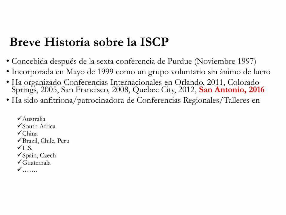
Breve Historia sobre la ISCP
• Concebida después de la sexta conferencia de Purdue (Noviembre 1997)
• Incorporada en Mayo de 1999 como un grupo voluntario sin ánimo de lucro
• Ha organizado Conferencias Internacionales en Orlando, 2011, Colorado Springs, 2005, San Francisco, 2008, Quebec City, 2012, San Antonio, 2016
• Ha sido anfitriona/patrocinadora de Conferencias Regionales/Talleres en
AustraliaSouth AfricaChinaBrazil, Chile, PeruU.S.Spain, CzechGuatemala…….
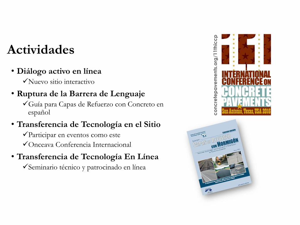
• Diálogo activo en línea
Nuevo sitio interactivo
• Ruptura de la Barrera de Lenguaje
Guía para Capas de Refuerzo con Concreto en español
• Transferencia de Tecnología en el Sitio
Participar en eventos como este
Onceava Conferencia Internacional
• Transferencia de Tecnología En Línea
Seminario técnico y patrocinado en línea
concretepavements.org/11thiccp
Actividades

Comité de Ejecutivo - ISCP
President: Dr. Jeff Roesler, University of Illinois
Vice-President: Byran Perrie, The Concrete Institute (South Africa)
Treasurer-Secretary: Dr. Jake Hiller, Michigan Tech Univ. (USA)
Past President: Dr. Neeraj Buch, Michigan State (USA)

Miembros de Board - ISCP
Dr. Lev Khazanovich, University of Minnesota (USA)
Corey Zollinger, CEMEX (USA)
Dr. Rolf Breitenbücher, Ruhr-University (Germany)
Leif Wathne, American Concrete Pavement Association (USA)
Juan Pablo Covarrubias, TCPavements, Ltda. (Chile)
George Vorobieff, RTA (Australia)
Dr. Someyah Nassiri, Washington State (USA)
Tim Smith, Lafarge-Holcim (Canada)
Luc Rens, EUPAVE (Belgium)
Sherry Sullivan, Cement Association of Canada
Erwin Kohler, 3ipe (Chile)
Anne-Carin Brink, AECOM (Australia)
Dr. Peter Taylor, Iowa State University (USA)

100+ technical papers
14 Podium Sessions (~56 papers)
4 Poster Sessions (~45 posters)
Student Posters (~20 posters)
11 Workshops – practical, applied content (repeated)
Site visits – Steel plant, cement plant

Visitános• Nueva y mejorada página web
www.concretepavements.org
• Miembro Individual
• Miembro Corporativo
-Gold
-Silver
-Bronze

Recapados de Hormigón (O/L)
(Vista general)
Overlay Design Objectives
Overlay Design Guides
Inputs & critical variables
Bonded Concrete Overlays
Concrete-Asphalt
Performance of Illinois O/L
Unbonded Concrete Overlays
Summary of Overlay Design
References for O/L design
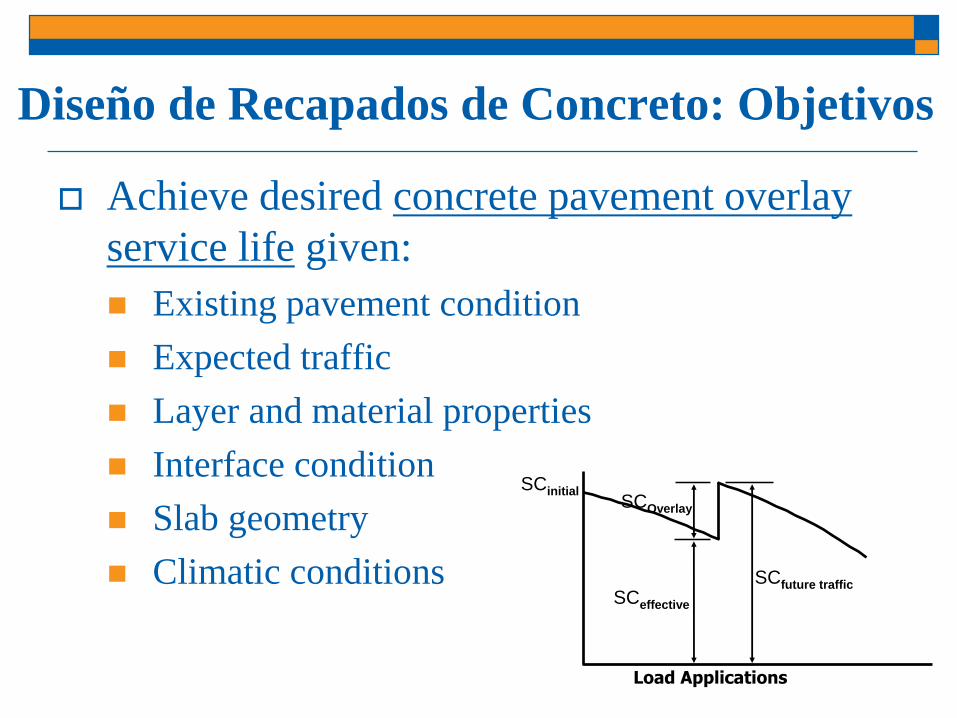
Diseño de Recapados de Concreto: Objetivos
Achieve desired concrete pavement overlay
service life given:
Existing pavement condition
Expected traffic
Layer and material properties
Interface condition
Slab geometry
Climatic conditions
SCinitialSCOverlay
SCeffective
SCfuture traffic
Load Applications
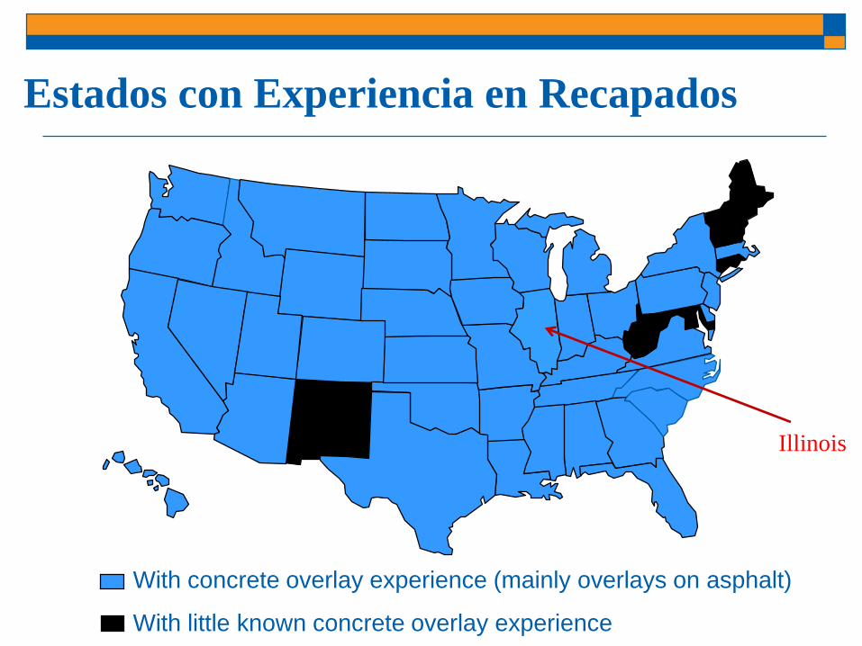
Estados con Experiencia en Recapados
With concrete overlay experience (mainly overlays on asphalt)
With little known concrete overlay experience
Illinois

Recapados de Hormigón
en Illinois (2015)
17
Overlay Type - 97
Bonded (PCC/PCC)(12)
Unbonded (PCC/Comp.)(11)
Whitetopping (UB) (15)
UTW or WT (B) (46)
UTW/Unbonded Hybrid (13)
http://www.ilacpa.com/Whitetopping%20Links/Project_List.pdf

Como minimo 1000 proyectosrecapados en EEUU.
911 Items filtered from 1207

Guía en Métodos Existentes de Diseño de
Recapados
Not a design procedure
Background on
recommended overlay
design methods
18 pages
Detailed design examples
35 pages
StreetPave12 released
after this guide
http://www.cptechcenter.org/technical-library/documents/Overlays_Design_Guide_508.pdf

Cómo empezar el diseño del concreto O/L?
Roadway site evaluation
Existing pavement structure
New pavement performance objectives
Select potential Overlay Options
Collect input data & choose design features
Support layers, Slab size, etc.
Use appropriate overlay design methods
Optimize design
Write construction specifications to reflect design
objectives

Recapados de Concreto: Tipos Generales
Whitetopping (unbonded) Bonded Concrete Overlay Asphalt (BCOA)
Bonded Concrete to Concrete Unbonded Concrete w/ Separation Layer
Not common
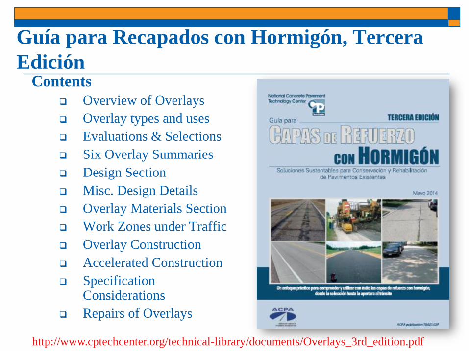
Guía para Recapados con Hormigón, Tercera
EdiciónContents
Overview of Overlays
Overlay types and uses
Evaluations & Selections
Six Overlay Summaries
Design Section
Misc. Design Details
Overlay Materials Section
Work Zones under Traffic
Overlay Construction
Accelerated Construction
Specification Considerations
Repairs of Overlays
http://www.cptechcenter.org/technical-library/documents/Overlays_3rd_edition.pdf
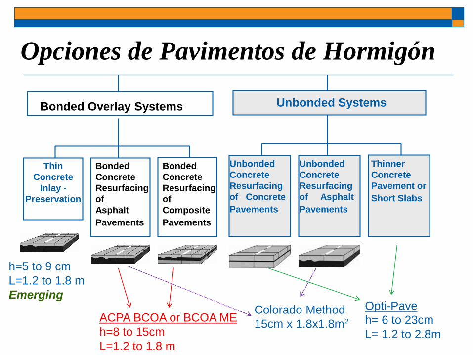
Opciones de Pavimentos de Hormigón
Bonded
Concrete
Resurfacing
of
Asphalt
Pavements
Bonded
Concrete
Resurfacing
of
Composite
Pavements
Bonded Overlay Systems
Unbonded
Concrete
Resurfacing
of Concrete
Pavements
Unbonded
Concrete
Resurfacing
of Asphalt
Pavements
Thinner
Concrete
Pavement or
Short Slabs
Unbonded Systems
ACPA BCOA or BCOA ME
h=8 to 15cm
L=1.2 to 1.8 m
Thin
Concrete
Inlay -
Preservation
h=5 to 9 cm
L=1.2 to 1.8 m
Emerging
Colorado Method
15cm x 1.8x1.8m2
Opti-Pave
h= 6 to 23cm
L= 1.2 to 2.8m

¿Qué metodo(s) de Recapados con concreto?
Concrete Overlay Type Design Methods
Unbonded on Asphalt,
Composite, or Concrete
AASHTO ME, ACPA StreetPave 12,
AASHTO 93, OptiPave 2.0
Bonded on Asphalt or
Composite
ACPA BCOA, ACPA StreetPave 12,
BCOA ME, CO 6x6x6, IDOT Chpt 53
Bonded on Concrete AASHTO ME, ACPA StreetPave 12,
AASHTO 93

• Slab thickness
• Concrete Strength, CTE, Modulus, fibers
• Concrete-Asphalt Interface
• Support layers (surface, base/subbase, soil)
• Joint Spacing
• Edge Support
• Load Transfer
• Subgrade Support
• Traffic & Design Life
• Climate
¿Cuáles son los principales factores de diseño para
las Recapados con Concreto?
Hamilton County, IL
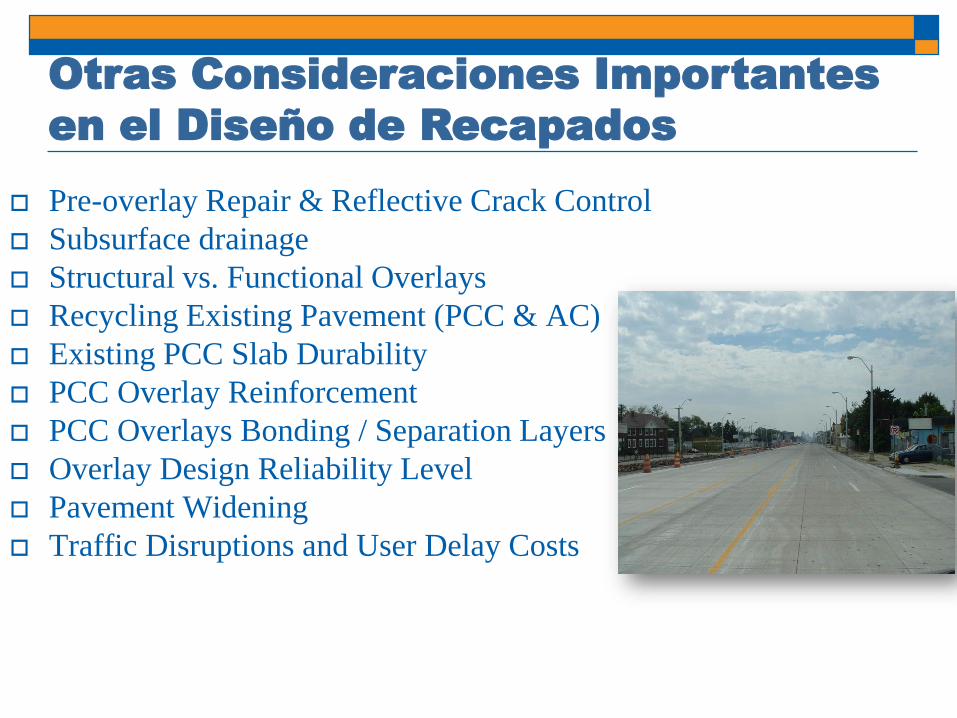
Pre-overlay Repair & Reflective Crack Control
Subsurface drainage
Structural vs. Functional Overlays
Recycling Existing Pavement (PCC & AC)
Existing PCC Slab Durability
PCC Overlay Reinforcement
PCC Overlays Bonding / Separation Layers
Overlay Design Reliability Level
Pavement Widening
Traffic Disruptions and User Delay Costs
Otras Consideraciones Importantes
en el Diseño de Recapados

UTW vs. Whitetopping
Whitetopping (h > 15cm)
Slab sizes (3.5m to 4.5m)
35+ years experience
No interface bond assumed
Ultra-Thin Whitetopping (h ≤ 15cm)
20 years experience
Smaller slab sizes (<2m)
PCC/AC bond is essential
Now called Bonded Concrete Overlay of Asphalt (BCOA)

Mecánica del Comportamiento de Materiales
Compuestos
Unbonded
“Whitetopping”
Neutral Axis
PCC
AC
Bonded
Bonded Concrete Overlay Asphalt
PCC
AC
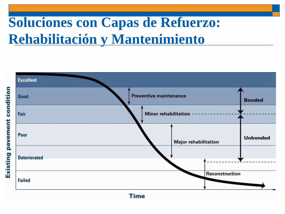
Soluciones con Capas de Refuerzo:
Rehabilitación y Mantenimiento

Visita al Sitio: Condición del Pavimento Existente

¿Por qué usar losas pequeñas?
1.2m 1.2m1.2m>3m
•Interface bond assumption for bonded overlays-Reduce de-bonding of concrete and asphalt at early ages
•Short slab sizes reduce bending and curling stresses

Diseño del Espesor de Recapados
Highways/Roads
AASHTO Pavement ME (2011) or MEPDG
StreetPave 12 (ACPA)
ACPA (Whitetopping/UTW) – 1998
Illinois DOT (2009) – new fatigue eqn. & fibers
Chapter 53-4.08
BCOA Calculator (2012) – add climate database
BCOA ME (2012) – Univ. of Pittsburg
AASHTO (1993)
Opti-Pave 2.0 (Covarrubias)
Airports:
Federal Aviation Administration (FAARFIELD)

Opciones de Recapados Adheridas
Thinner overlays (8 to 15 cm)
Constructed over concrete,
asphalt, and composite
sections.
Existing pavement condition
fair to good not poor!
Interface Bond is Critical!
Bonded
Concrete
Resurfacing
of
Concrete
Pavements
Bonded
Concrete
Resurfacing
of
Asphalt
Pavements
Bonded
Concrete
Resurfacing
of
Composite
Pavements
Bonded Overlay Options
X

Capa de Refuerzo de Concreto: Adherida al
Asfalto Metodos
AASHTO 1993
Not applicable
AASHTO Pavement ME (2011)
Thickness 15 cm
Slab length 3 m
ACPA (2012);IDOT (2009);Pitt BCOA ME (2013)
Ultra-Thin Whitetopping
Thickness 15 cm
Slab length 1.8 m
Unbonded Concrete
Overlay of HMAX

Capas Delgadas de Refuerzo con Concreto
para Pavimentos de Asfalto (UTW) Relatively Thin Slabs
(8 to 15cm)Square Slabs
(1.2mx1.2m to 1.8mx1.8m)
Milled Surface
preferred

HMA
PCC
Base
40kN 40kN
EAC, uAC
EPCCst
eAC
Subgrade k-value
Bonded
hPCC
hAC
UTW Lugares Críticos (Concreto y Capas AC)
st
If you lose bond
With bond,
corner loading
critical
L

Concrete Fatigue Model - UTW
217.024.10
0112.0
)1log(log
pSRN f
Model Statistics
N = 87
R2 = 91 percent
RMSE = 0.31 (log N)
Nf = Allowable repetitions to failure
SR = stress ratio (s/MOR)
p = probability of failure
Riley et al. (2005)
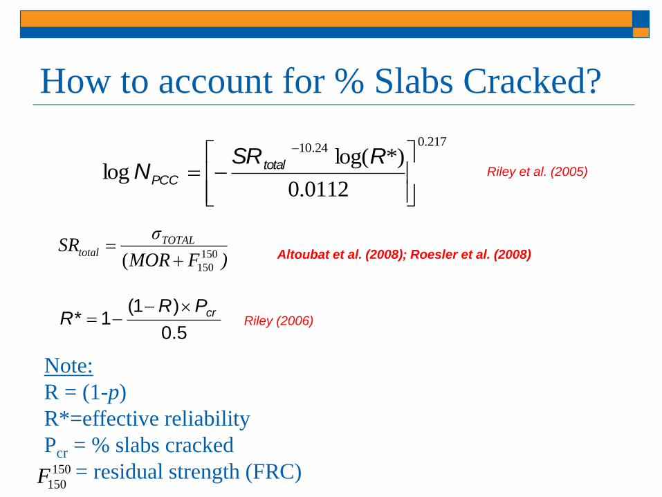
How to account for % Slabs Cracked?
217.024.10
0112.0
*)log(log
RSR
N total
PCC
)FMOR
σSR TOTAL
total 150
150(
5.0
)1(1* crPR
R
Note:
R = (1-p)
R*=effective reliability
Pcr = % slabs cracked
= residual strength (FRC)
Riley et al. (2005)
Altoubat et al. (2008); Roesler et al. (2008)
Riley (2006)
150
150F

Fibras Estructurales vs. no-estructurales (plastic
shrinkage)
Structural
Macro-Fibers
Micro-Fibers
(non-structural)
0
1
2
3
4
5
0 10 20 30 40CMOD (mm)
Load (
kN
)
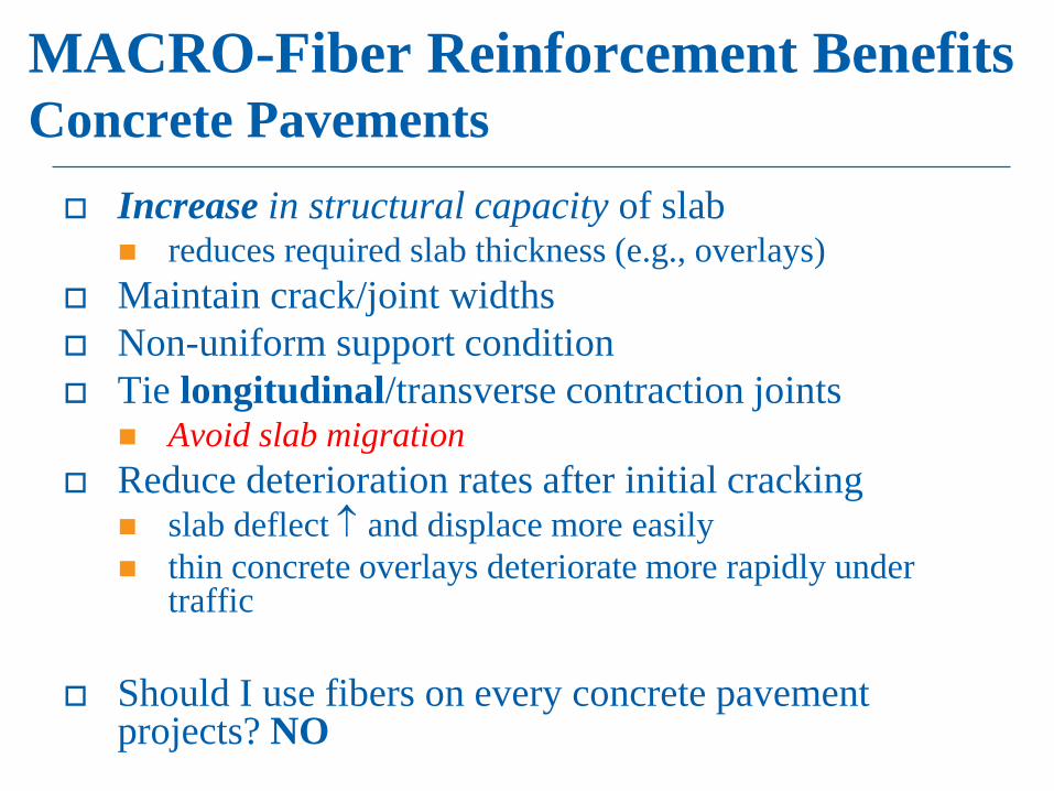
MACRO-Fiber Reinforcement BenefitsConcrete Pavements
Increase in structural capacity of slab reduces required slab thickness (e.g., overlays)
Maintain crack/joint widths
Non-uniform support condition
Tie longitudinal/transverse contraction joints Avoid slab migration
Reduce deterioration rates after initial cracking slab deflect and displace more easily
thin concrete overlays deteriorate more rapidly under traffic
Should I use fibers on every concrete pavement projects? NO

ASTM C1609-10Flexural Performance of Fiber-Reinforced Concrete (Third-Point Loading)
Need:
Deflection controlled loading frame
Mid-span deflection gauge
Pin/roller supports
Recommendations:
Beam sizes 150x150x500 mm (6x6x20 in.)
Fibers length < 3*D
Test process:
Load at constant deflection rate until L/150 reached
L = span of beam
D = depth of beam
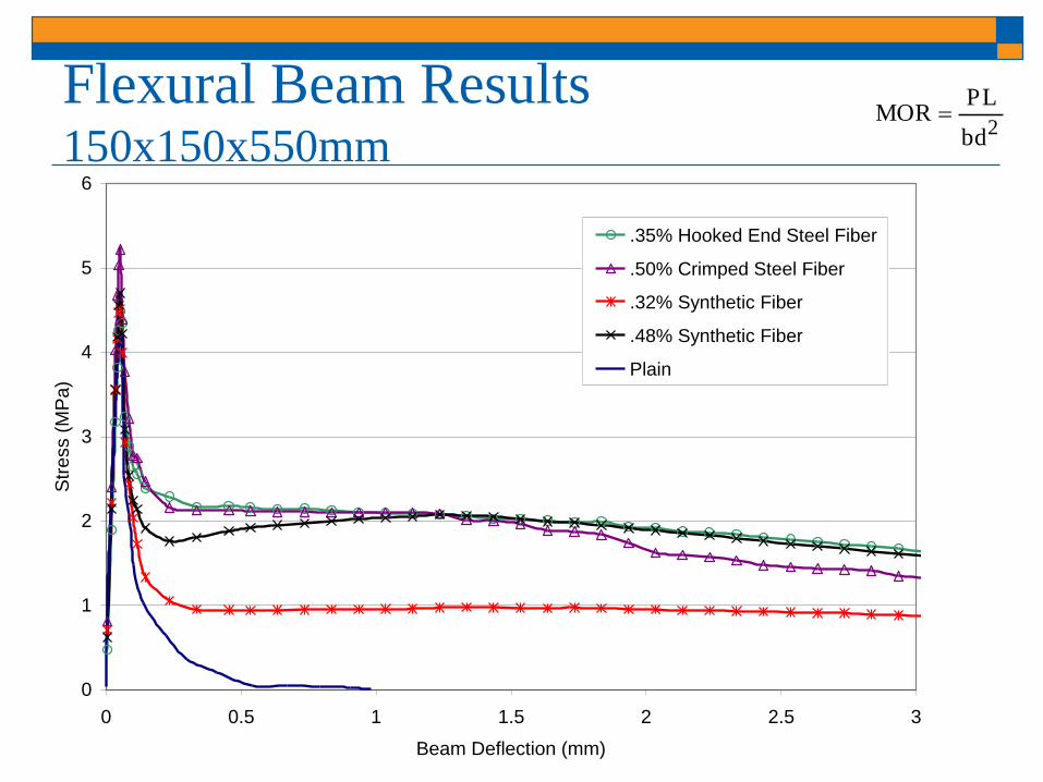
Flexural Beam Results150x150x550mm
2bd
PLMOR
0
1
2
3
4
5
6
0 0.5 1 1.5 2 2.5 3
Beam Deflection (mm)
Str
ess (
MP
a)
.35% Hooked End Steel Fiber
.50% Crimped Steel Fiber
.32% Synthetic Fiber
.48% Synthetic Fiber
Plain
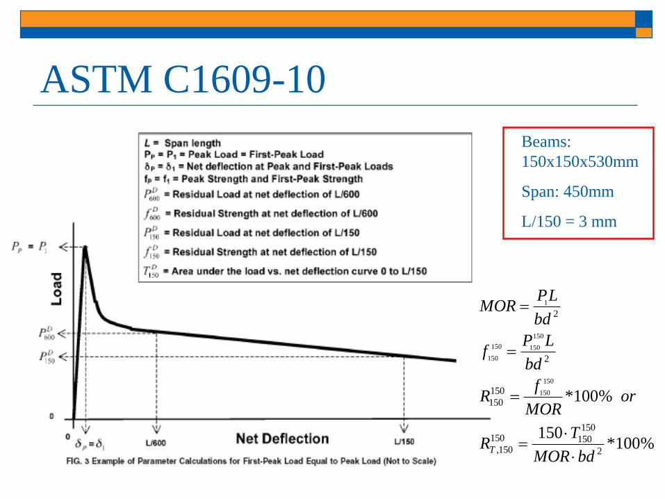
ASTM C1609-10
Beams:
150x150x530mm
Span: 450mm
L/150 = 3 mm
%100*150
%100*
2
150
150150
150,
150
150
2
2
150
150
150
150150
150
1
bdMOR
TR
orMOR
fR
bd
LPf
bd
LPMOR
T

Slab Test Setup
0
25
50
75
100
125
150
175
200
225
250
0 1 2 3 4 5 6 7 8 9 10 11 12 13
Maximum Surface Deflection at the Slab's Center (mm)
Lo
ad
(k
N)
Plain
0.48% Synthetic Fiber
0.32% Synthetic Fiber
0.35% Hooked End Steel Fiber
0.50% Crimped Steel Fiber
WWR
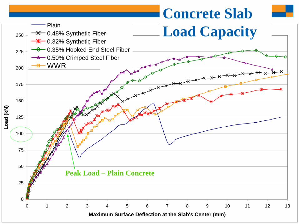
0
25
50
75
100
125
150
175
200
225
250
0 1 2 3 4 5 6 7 8 9 10 11 12 13
Maximum Surface Deflection at the Slab's Center (mm)
Lo
ad
(kN
)
Plain
0.48% Synthetic Fiber
0.32% Synthetic Fiber
0.35% Hooked End Steel Fiber
0.50% Crimped Steel Fiber
WWR
Peak Load – Plain Concrete
Concrete Slab
Load Capacity

Failure Load Summary (kN)
Slab Type Tensile Flexural Ultimate
Plain 75 108 135
Synthetic
(0.48%)70 143 195
Synthetic
(0.32%)75 135 174
Hooked Steel
(0.35%)70 141 228
Crimped Steel
(0.50%)90 167 220
WWR 65 122 201
Slab/Beam
Flex. Strength
1.39
2.09
1.82
2.01
2.22
1.53
Roesler et al. (2004)
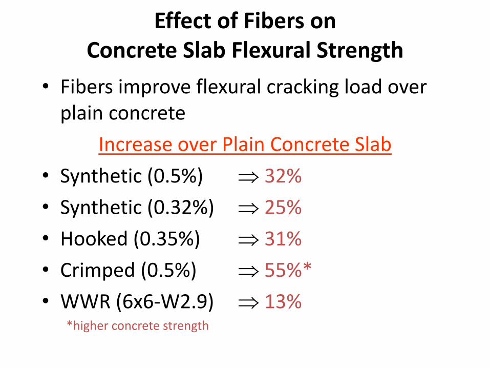
Effect of Fibers on Concrete Slab Flexural Strength
• Fibers improve flexural cracking load over plain concrete
Increase over Plain Concrete Slab
• Synthetic (0.5%) 32%
• Synthetic (0.32%) 25%
• Hooked (0.35%) 31%
• Crimped (0.5%) 55%*
• WWR (6x6-W2.9) 13%*higher concrete strength
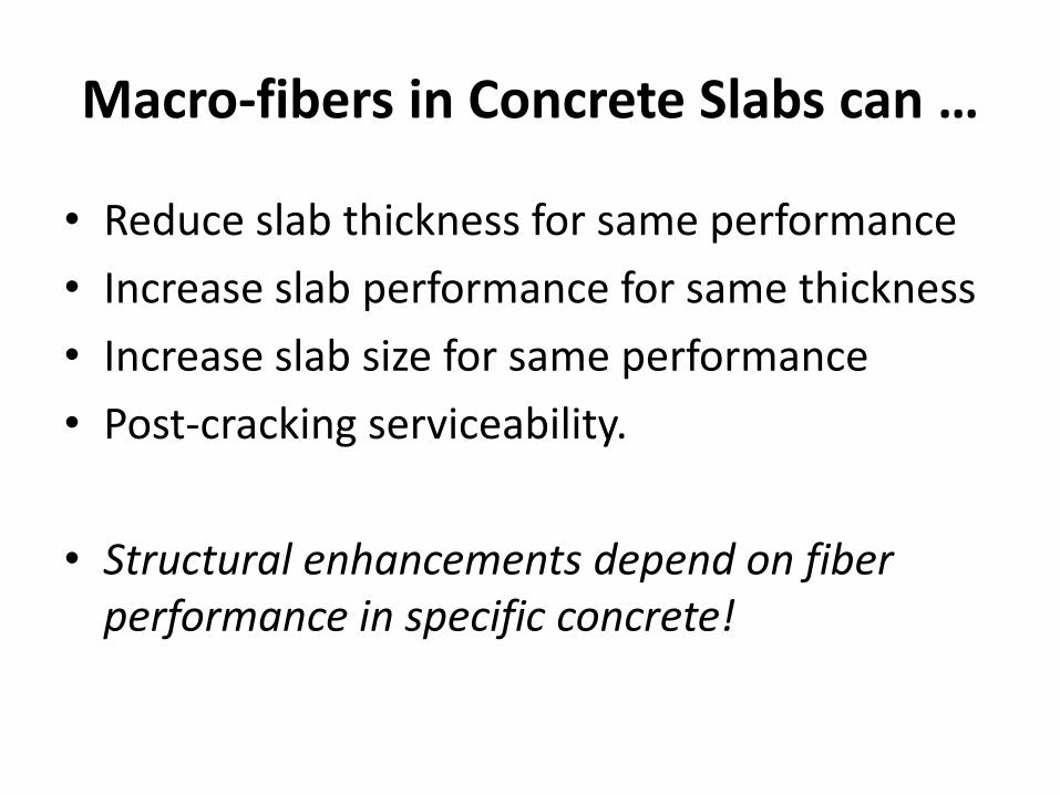
Macro-fibers in Concrete Slabs can …
• Reduce slab thickness for same performance
• Increase slab performance for same thickness
• Increase slab size for same performance
• Post-cracking serviceability.
• Structural enhancements depend on fiber performance in specific concrete!
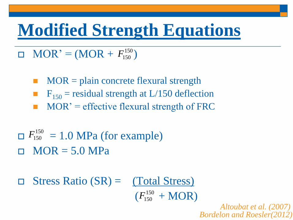
Modified Strength Equations
MOR’ = (MOR + )
MOR = plain concrete flexural strength
F150 = residual strength at L/150 deflection
MOR’ = effective flexural strength of FRC
= 1.0 MPa (for example)
MOR = 5.0 MPa
Stress Ratio (SR) = (Total Stress)
( + MOR)
150
150F
Bordelon and Roesler(2012)Altoubat et al. (2007)
150
150F
150
150F

Cálculo IDOT del Espesor del Concreto
Variable
Design Traffic Factor (BDE Manual, Figure 54-4C) TF 2.50
Modulus of Rupture (3-point bending, 14-day average) MOR 750 psi MOR
FRC Residual Strength Ratio 20%
Remaining Thickness of Asphalt h ac 3.0 in.
Joint Spacing L 72 in. L
Elastic Modulus of Concrete E c 3,600,000 psi E c
Coefficient of Thermal Expansion CTE 5.50E-06 in./in./°F CTE
Elastic Modulus of Asphalt E AC 350,000 psi
Modulus of Subgrade Reaction k 100 pci
k
Thickness of Concrete h c 5.48in.
Solved
Note 1: The design MOR is the mean design strength, not the minimum 550 psi flexural strength (center-point loading)
specified for opening to traffic. Also note that as MOR increases the risk of debonding increases and the effectiveness of
synthetic fibers decreases.
PCC Inlay / Overlay Design Sheet, Required Thickness of PCC
5.50 x 10⁻⁶
in./in./°F
E AC
100,000 psi (poor)
350,000 psi (moderate)
3,600,000 psi
0% (w/o fiber reinforcement)
20% (w/ fiber reinforcement)
600,000 psi (good)
100 pci
Default InputsDefault Value
750 psi (Note 1)
48 in. or 72 in.
150150R
Compute Concrete
Thickness
Help
150150R
http://www.dot.state.il.us/desenv/pdp.html
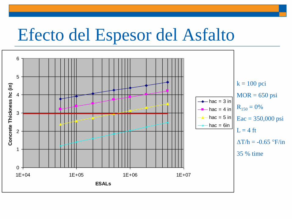
Efecto del Espesor del Asfalto
0
1
2
3
4
5
6
1E+04 1E+05 1E+06 1E+07
ESALs
Co
ncre
te T
hic
kn
ess h
c (
in)
hac = 3 in
hac = 4 in
hac = 5 in
hac = 6in
k = 100 pci
MOR = 650 psi
R150 = 0%
Eac = 350,000 psi
L = 4 ft
ΔT/h = -0.65 °F/in
35 % time

R150= Relación de Resistencia Residual (Fibras)
0
1
2
3
4
5
6
1E+04 1E+05 1E+06 1E+07
ESALs
Co
ncre
te T
hic
kn
ess h
c (
in)
R150,3 = 0%
R150,3 = 15%
R150,3 = 20%
R150,3 = 25%
k = 100 pci
MOR = 650 psi
Eac = 350,000 psi
hac = 3 in
L = 4 ft
ΔT/h = -0.65 °F/in
35 % time

Efecto del Tamaño de la Losa (L)
0
1
2
3
4
5
6
7
8
1E+04 1E+05 1E+06 1E+07
ESALs
Co
ncre
te T
hic
kn
ess h
c (
in)
L = 12 ft
L = 6 ft
L = 4 ft
k = 100 pci
MOR = 650 psi
R150 = 0%
Eac = 350,000 psi
hac = 3 in
ΔT/h = -0.65 °F/in
35 % time
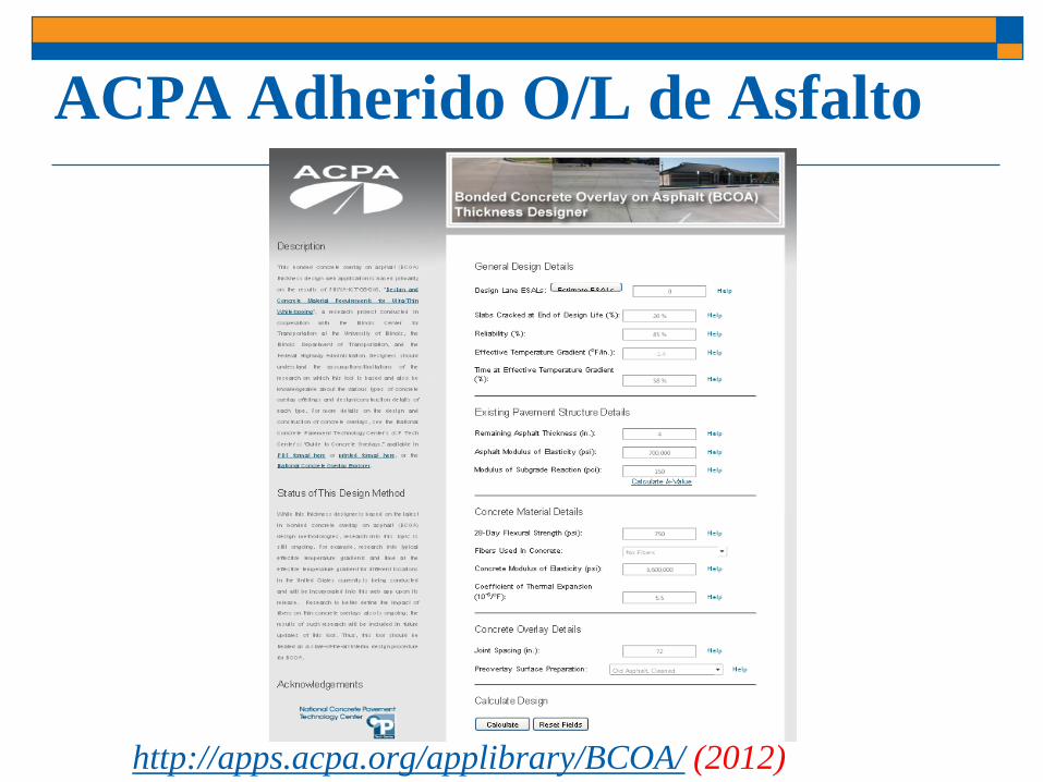
ACPA Adherido O/L de Asfalto
http://apps.acpa.org/applibrary/BCOA/ (2012)

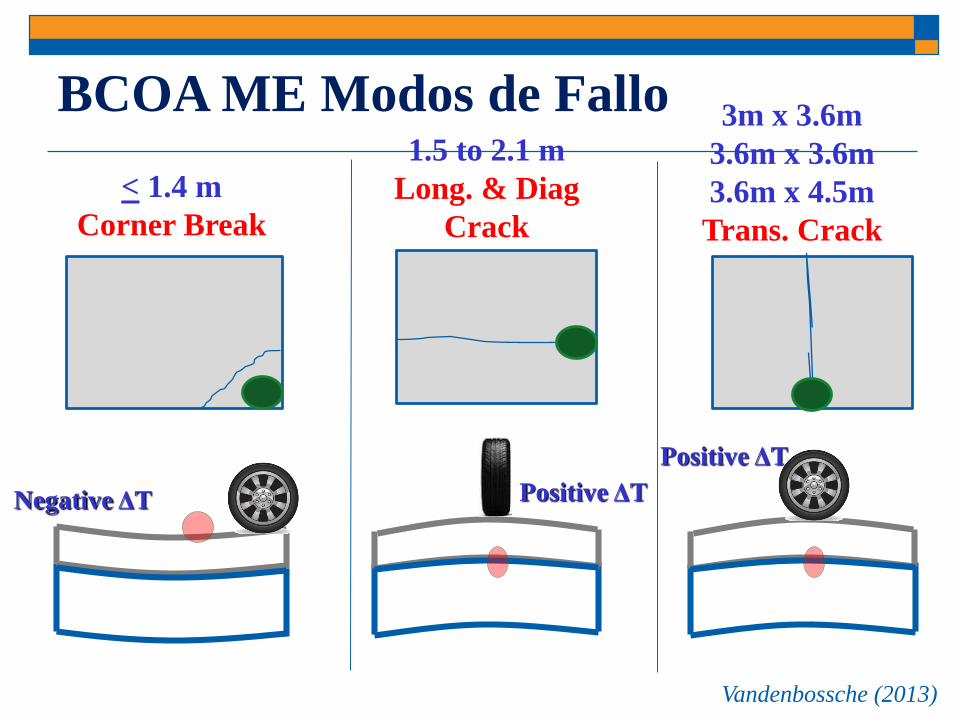
BCOA ME Modos de Fallo1.5 to 2.1 m
Long. & Diag
Crack
Positive ΔT Negative ΔT
< 1.4 m
Corner Break
Positive ΔT
3m x 3.6m
3.6m x 3.6m
3.6m x 4.5m
Trans. Crack
Vandenbossche (2013)
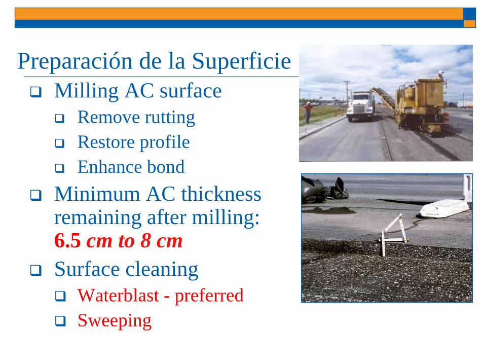
Preparación de la Superficie
Milling AC surface
Remove rutting
Restore profile
Enhance bond
Minimum AC thickness remaining after milling: 6.5 cm to 8 cm
Surface cleaning
Waterblast - preferred
Sweeping

Guía sobre Capas de
Refuerzo para
Estacionamientos (2012)
www.rmc-foundation.org/images/Concrete_Overlay_Guide_11-14-12.pdf
Contents:
Parking Lot Features
Existing Pavement Condition
Concrete Overlay Design
Jointing
Parking lot details
Materials
Construction
Fibers

University of Illinois: Estacionamiento E-15
(2006)
8 cm overlay over existing 6.4 cm HMA surface
1.2m x 1.2m panels
1.8 kg/m3 structural synthetic fibers
2012
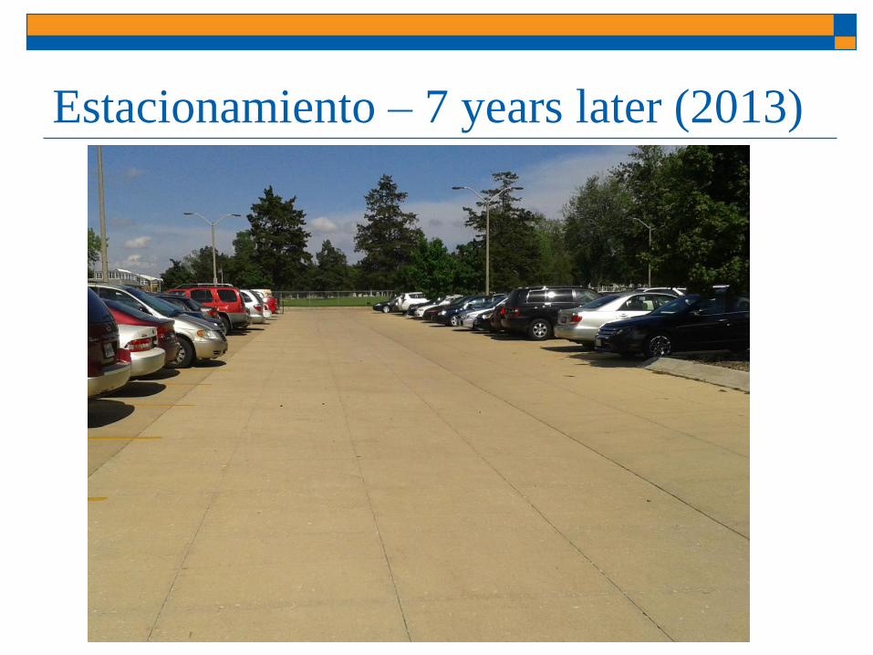
Estacionamiento – 7 years later (2013)

Nueva sección UTW (1 year - 2013)

2007 Proyecto Estacionamiento McKinley
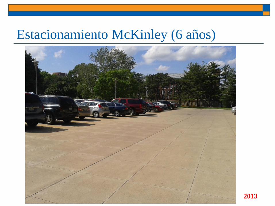
Estacionamiento McKinley (6 años)
2013
DESEMPEÑO DE SECCIONES UTW
(WHITETOPPING
ULTRA-DELGADO)


Proyectos Visitados en Illinois (20)
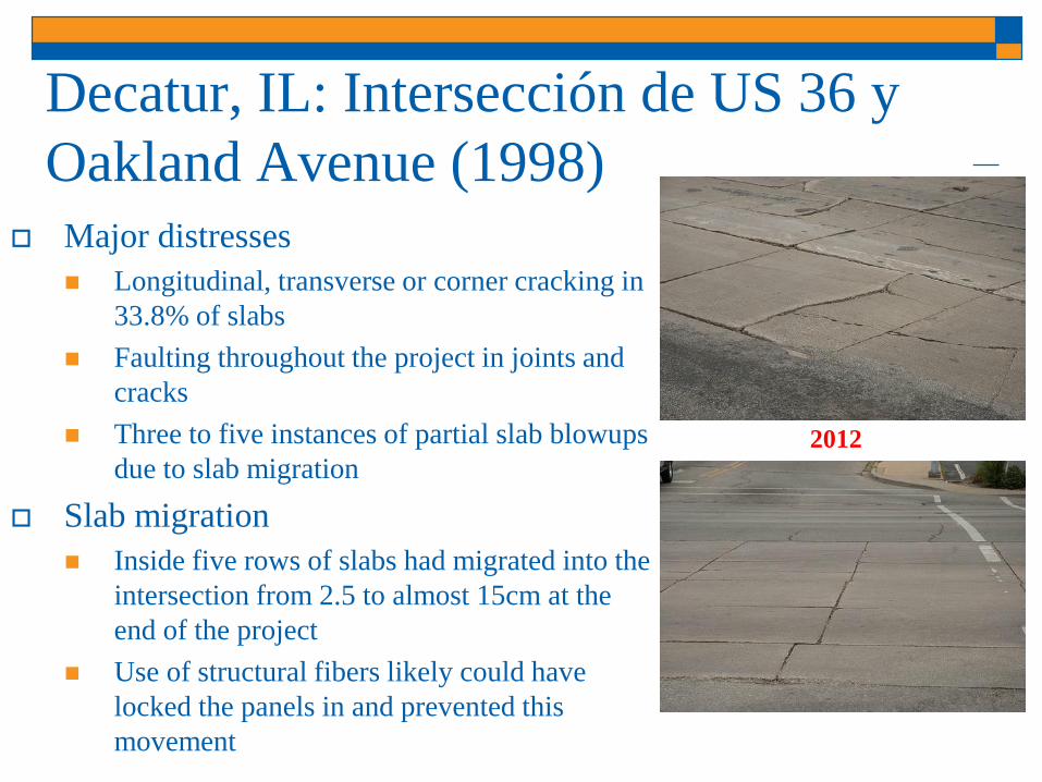
Decatur, IL: Intersección de US 36 y
Oakland Avenue (1998)
Major distresses
Longitudinal, transverse or corner cracking in
33.8% of slabs
Faulting throughout the project in joints and
cracks
Three to five instances of partial slab blowups
due to slab migration
Slab migration
Inside five rows of slabs had migrated into the
intersection from 2.5 to almost 15cm at the
end of the project
Use of structural fibers likely could have
locked the panels in and prevented this
movement
2012

Tuscola, IL: US 36 (1999)
Major Issues
Slab migration in opposite directions
in the EB and WB lanes
Water buildup between the outside
slabs and the shoulder
High severity faulting
Joints falling in the wheelpath
Longitudinal, transverse or corner
cracking in 25.6% of slabs
Slab misalignment magnifies
roughness
2012

Kane County, IL: Carretera North Lorang (2004)
11 cm thick concrete overlay of 7.5-9 cm of HMA over
aggregate base
2.4 kg/m3 synthetic macro-fibers
Square 1.5m x 1.5m panels
Project built to serve a quarry: average of 30 trucks/day (peak
of 280/day)
2012

Mundelein, IL: Schank Avenue (2005)
10cm. concrete overlay of a composite pavement (5.7-16.5cm
HMA over 12-23.5cm PCC)
Square 1.2m x 1.2m panels
2.4 kg/m3 synthetic macro-fibers
High truck traffic volume (no data available, but comparable
to Lorang Road and more general traffic)
2012

Hamilton County, IL (2014)
FRC UTW (10cm)
Existing Asphalt Concrete (7.5cm)
Cement Treated Soil (20cm)
Natural Soil

Built in 2013
Built in 9/2014
Built in 9/2014
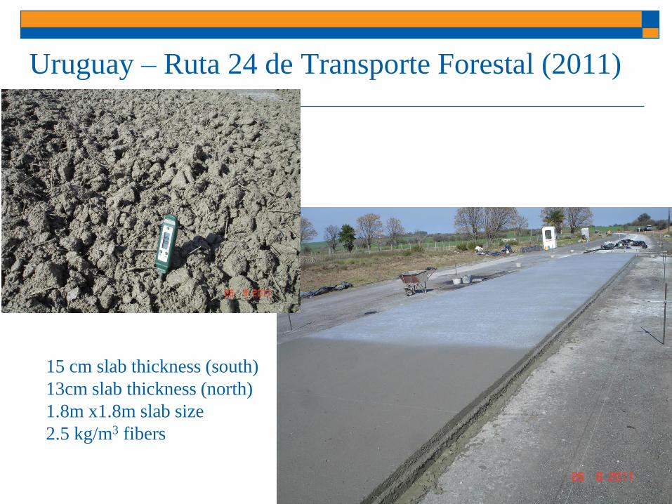
Uruguay – Ruta 24 de Transporte Forestal (2011)
15 cm slab thickness (south)
13cm slab thickness (north)
1.8m x1.8m slab size
2.5 kg/m3 fibers

Ruta 24 – 23 Octubre 2016
15 cm slab thickness
1.8m x1.8m slab size
2.5 kg/m3 fibers IRI = 2.0m/km
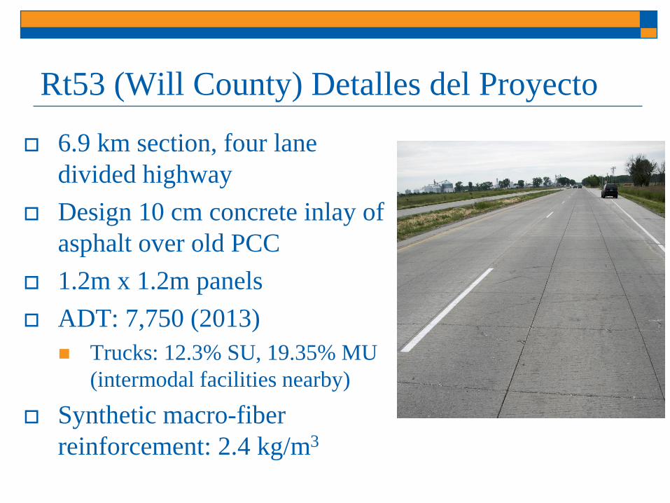
Rt53 (Will County) Detalles del Proyecto
6.9 km section, four lane
divided highway
Design 10 cm concrete inlay of
asphalt over old PCC
1.2m x 1.2m panels
ADT: 7,750 (2013)
Trucks: 12.3% SU, 19.35% MU
(intermodal facilities nearby)
Synthetic macro-fiber
reinforcement: 2.4 kg/m3

Encuesta de Deterioro
Severe distresses near lane-shoulder joint
along right edge of the northbound pavement
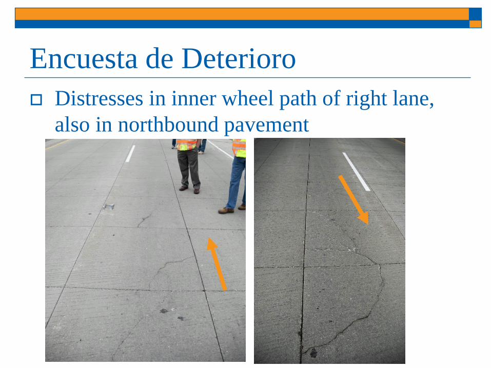
Encuesta de Deterioro
Distresses in inner wheel path of right lane,
also in northbound pavement

UTW Testigos (Cores)
Average layer thicknesses from cores taken in
Summer 2014
9 cores in each direction (right lane, center panels)
Difference between concrete and asphalt layer
thicknesses in NB & SB directions statistically
significant with 95% confidence
Direction UTW Concrete
Thickness
(inches)
Asphalt
Thickness
(inches)
Old Concrete
Thickness
(inches)
Northbound 3.86 4.03 9.0
Southbound 4.56 5.06 5.7
Resumen: IL 53 fallas prematuras
Cross slope (pendiente) <1.0% in northbound
Water entered longitudinal joints
1.2mx1.2m slab size detrimental
Very old asphalt layer directly beneath slabs
Signficant de-bonding of concrete-asphalt layers
Heavier trucks than anticipated
Note, southbound lanes are fine
-no major distresses
Retrocálculo de UTW
What do we expect from FWD tests?
What assumptions do we need to make?
What equations do we use?

UTW Modelado de Pavimento
Fixed Input Parameters
Load, P 9,000 lb
Plate Radius, a 6.0 in
Modulus of Subgrade Reaction, k 100 psi/in
Poisson’s Ratio, ν 0.15
Modulus of Elasticity, E 5,000,000 psi
UTW pavement
system was modeled in
Illislab as an effective
concrete slab over
subgrade• Derive relationships
that determine heff

Equaciones de Retrocálculo
𝐴𝑅𝐸𝐴24 = 6 1 + 2𝑑12𝑑0
+𝑑24𝑑0
10 15 20 25 30 35 40 45
16
17
18
19
20
21
22
23
24 LTE=100
LTE=80
LTE=50
LTE=0
AR
EA
-24 (
in)
Radius of Relative Stiffness, l (in)
𝑊𝑖𝑛𝑡 =𝑑0𝑘𝑙
2
𝑃= 𝑓
𝑎
0.10 0.15 0.20 0.25 0.30 0.35 0.40 0.45
100
200
300
400
500
600
700
800
LTE=100
LTE=80
LTE=50
LTE=0
Win
t (-
)
a/l (-)
=𝐸ℎ3
12 1 − 𝜈2 𝑘
1/4
King and Roesler (2014) Transportation Research Record: Journal of the Transportation Research Board, No. 2457, pp. 72–79.
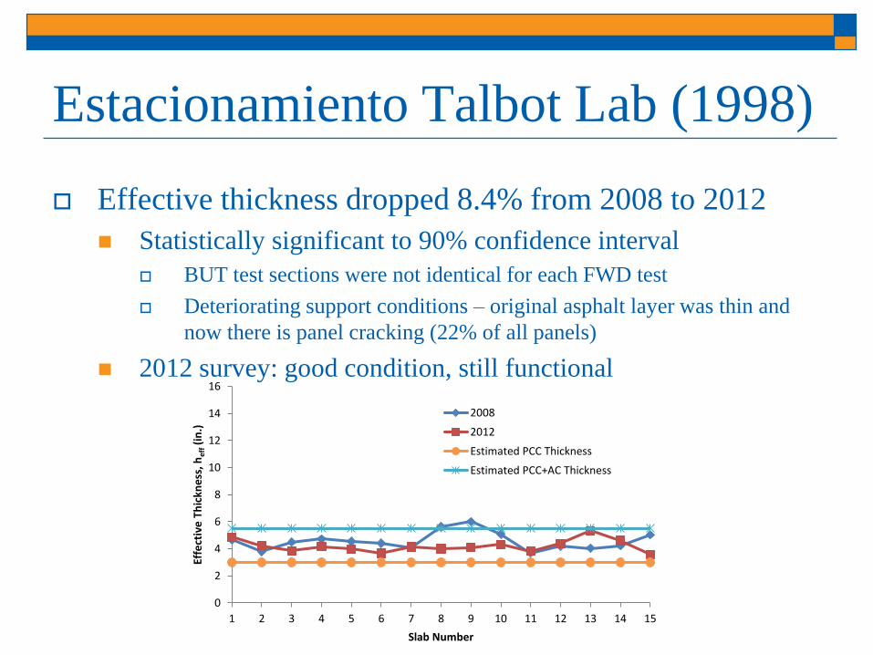
Estacionamiento Talbot Lab (1998)
Effective thickness dropped 8.4% from 2008 to 2012
Statistically significant to 90% confidence interval
BUT test sections were not identical for each FWD test
Deteriorating support conditions – original asphalt layer was thin and
now there is panel cracking (22% of all panels)
2012 survey: good condition, still functional
0
2
4
6
8
10
12
14
16
1 2 3 4 5 6 7 8 9 10 11 12 13 14 15
Effe
ctiv
e T
hic
kne
ss, h
eff(i
n.)
Slab Number
2008
2012
Estimated PCC Thickness
Estimated PCC+AC Thickness

Resultados del Proyecto
0
2
4
6
8
10
12
14
1 2 3 4 5 6 7 8 9 10 11 12 13 14 15
Eff
ecti
ve
Th
ick
nes
s, h
eff (i
nch
es)
Slab Number
Section 1
Section 2
Section 3
Estimated PCC Thickness
Project, Location (year) &
Panel Size Section
Average Modulus
of Subgrade
Reaction, k (pci)
Average
Effective Slab
Thickness (in)
Thickness
Standard
Deviation (in)
Estimated
Thickness: hPCC +
hAC = htotal (in)
North Lorang Road, Kane
County, IL (2004),
4 ft x 4 ft
1 156 5.89 1.85
4.5 (PCC only)2 394 8.39 1.32
3 379 7.47 0.801
Variable LTE affects backcalculation

Resúmen: Recapados con Concreto Parking lots = 1.2mx1.2m panels are fine w/ fibers
Maintain ~1.8m panel sizes w/ fibers
More cracking/faulting on skewed joints
Thinner saw blades
No sealing except when long. joint in wheel path
No faulting or cracking on 1.2mx1.2m or 1.8mx1.8m slab sizes with macrofibers (>2006)
FRC needs minimum revolutions at high torque in mixer
AC layer or underlying support have potential to be major issues (e.g. Schank Ave) and/or heavy truck traffic, try higher fiber dosages or fix support layer
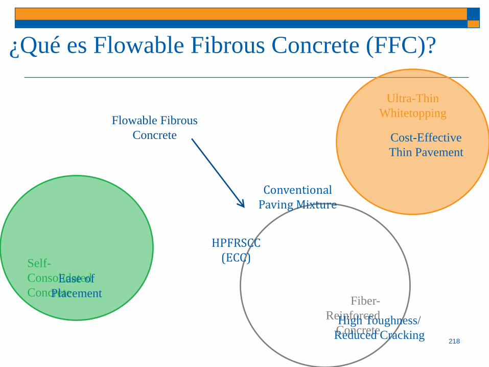
¿Qué es Flowable Fibrous Concrete (FFC)?
218
Flowable Fibrous
Concrete
Ultra-Thin
Whitetopping
Fiber-
Reinforced
Concrete
Self-
Consolidated
Concrete
High Toughness/
Reduced Cracking
Ease of
Placement
Cost-Effective
Thin Pavement
HPFRSCC (ECC)
Conventional Paving Mixture

Flowable Fibrous Concrete (FFC) para capas
intermedias delgadas de preservación
Lower speed applications
Slab thickness < 8 cm
10-year service life
Concrete wearing surface (Preservation)
Asphalt-concrete bond essential
Loads transmitted to substrate layers
Other sustainability enhancements:
Reflectivity, skid, air pollutant reducer
Bordelon & Roesler (2010)
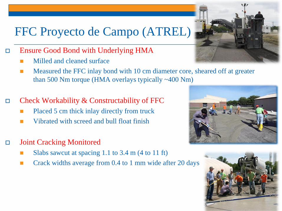
FFC Proyecto de Campo (ATREL)
Ensure Good Bond with Underlying HMA
Milled and cleaned surface
Measured the FFC inlay bond with 10 cm diameter core, sheared off at greater
than 500 Nm torque (HMA overlays typically ~400 Nm)
Check Workability & Constructability of FFC
Placed 5 cm thick inlay directly from truck
Vibrated with screed and bull float finish
Joint Cracking Monitored
Slabs sawcut at spacing 1.1 to 3.4 m (4 to 11 ft)
Crack widths average from 0.4 to 1 mm wide after 20 days
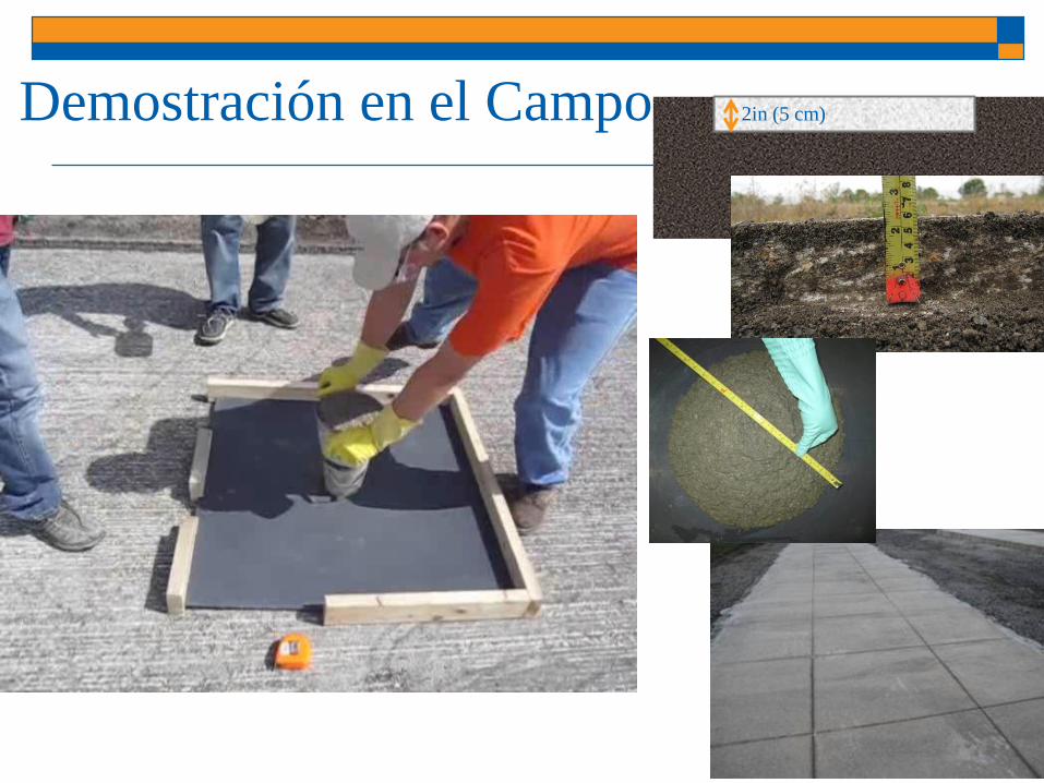
Demostración en el Campo 2in (5 cm)

Recapados con Hormigón Delgado
Adherido: Resúmen Existing pavement condition assessment
Select new concrete pavement type
Define interface assumption
Available structural design methods
IDOT BCOA (Chapter 53-4.08)
ACPA (BCOA Calculator)
Pitt BCOA ME
Fibers provide excellent benefits for BCOA
Surface & subsurface drainage
Construction details essential!
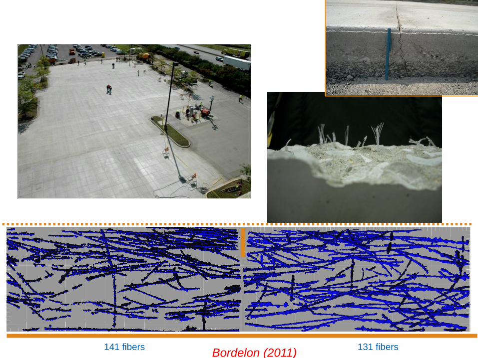
141 fibers 131 fibersBordelon (2011)

Agradecimientos
Illinois Department of Transportation Illinois Center for Transportation
www.ict.illinois.edu
Randell RileyIL-ACPA
Amanda Bordelon Asst. Prof. @ University of Utah
National Concrete Pavement Technology Center Dale Harrington
American Concrete Pavement Association (ACPA)
Daniel King (2012-2015) Research Assistant, UIUC
Dr. Julie Vandenbossche University of Pittsburg

Bibliografía
Harrington, D. et al. (2012), Guidance for the Design of Concrete Overlays Using Existing Methodologies, National Concrete Pavement Technology Center, Iowa State University, Ames, IA.
Roesler, J. R., Bordelon, A., Ioannides, A. M., Beyer, M., and Wang, D. (2008), Design and Concrete Material Requirements for Ultra-Thin Whitetopping, Final Report, Illinois Center for Transportation Series No. 08-016, University of Illinois, Urbana, IL, 181 pp.
Rasmussen, R., Rogers, R., Ferragut, T. (2009), Continuously Reinforced Concrete Pavements Design and Construction Guidelines, FHWA-CRSI.
Harrington, D. et al. (2014), Guide to Concrete Overlays Sustainable Solutions for Resurfacing and Rehabilitating Existing Pavements, National Concrete Pavement Technology Center, Iowa State University, Ames, IA.
Smith, K.D., H. Yu, D. Peshkin, (2002), Portland Cement Concrete Overlays: State of the Technology Synthesis, Federal Highway Administration, Washington, DC.
Vandenbossche (2011) Development of a Design Guide for Thin and Ultrathin Concrete Overlays of Existing Asphalt Pavements, TPF-5(165)