disinfection techniques - irc · 3.0 bleaching powder for ... 3«3 loss of chlorine on ......
TRANSCRIPT

6? / . ?^
2 5 4 . 2
6 9 D I
DISINFECTION TECHNIQUES
FOR
SMALL COMMUNITY WATER SUPPLIES
REPORT
PREPARED FOR
WORLD HEALTH ORGANIZATION
BY
CENTRAL PUBLIC HEALTH ENGINEERING RESEARCH INSTITUTE
NAGPUR, INDIA
1969
j&M-^'-tfflij

DISINFECTION TECHNIQUES
FOR
SMALL COMMUNITY WATER SUPPLIES
REPORT
PREPARED FOR
WORLD HEALTH ORGANIZATION
BY
CENTRAL PUBLIC HEALTH ENGINEERING RESEARCH INSTITUTE
NAGPUR, INDIA
. .' . / . '";i969^

R E P O R T ON
DISINFECTION TECHNIQUES
POR
SMALL COMMUNITY WATER SUPPLIES
Prepared by
Central Publ ic Health Engineering Research I n s t i t u t e
Nagpur-3, India

C O N T E N T S
Page No.
1.0 INTRODUCTION
2.0 TERMS OF REFERENCE
3 .0 BLEACHING POWDER FOR DISINFECTION
3 . 1 A v a i l a b i l i t y of Bleaching Powder in India
3 .2 Avai lable Standards
3«3 Loss of Chlorine on Storage
3.4 Working Hazard and Handling Requirements
3-5 Characteristics of Bleaching Powder Solution
3.6 Sludge Volume
3-7 Effect of Mixing Water Quality ?.nc; Temperature
3.6 Chemistry of Chlorination with Bleaching Powder
4.0 DISINFECTION OF OPEN DUG WELLS
4.1 Pot Chlorinetion of Wells
4.2 Porosity Determination
4.3 Pots with Holes in the Middle
4.4 Pots with Holes ct Bottom
4.5 Field Work
4.6 Double Pot System
4 7 Dr ip- type Chlor ina tor
4 .8 Dosing Device for Hand Pump
4 .9 Chlorine or Iodine Table t Dispenser
5 .0 ACCEPTIBILTTY OF CHLORINATED WELL WATERS BY VILLAGERS
6 .0 MECHANICAL PROPORTIONING DEVICES
6 .1 .0 Ventur i & E jec to r - type Ch lo r in» to r s
6 . 1 . 1 Ven tu r i - type Chlor ina to r
6 .1 .2 E j e c t o r - t y p e Chlor ina to r
6.2 Direct -Feed Device
6 .3 D i f f e r e n t i a l P res su re - type Ch lo r ina to r
7 .0 CHLORINE TEST KIT
SUMMARY AND CONCLUSIONS
1
3
5
6
8
8
10
10
12
12
14
15
16
18
20
22
24
26
28
34
35
37
38
38
38
42
42
45
48
50
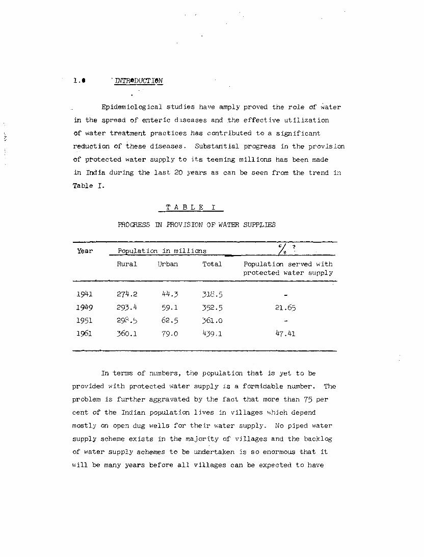
i . t • INTRODUCTION
Epidemiological s t u d i e s have amply proved the r o l e of water
in the spread of e n t e r i c d i s ea se s and the e f f e c t i v e u t i l i z a t i o n
of water t rea tment p r a c t i c e s has con t r i bu t ed t o a s i g n i f i c a n t
r educ t ion of t h e s e d i s e a s e s . S u b s t a n t i a l progress in t h e p rov i s ion
Of p ro tec t ed water supply t o i t s teeming mi l l i ons has been made
in India dur ing the l a s t 20 years as can be seen from the t r end in
Table I .
T A B L E I
PROGRESS IN PROVISION OP WATER SUPPLIES
Year Populat ion in m i l l i o n s JLL Rural Urban Total Population served with
protected water supply
1941
1949
1951
1961
274.2
293-4
29?. 5
360.1
kk.J>
59-1
62.5
79-0
318.5
352.5
361.0
439.1
21.65
47.41
In terms of numbers, the population that is yet to be
provided with protected water supply is a formidable number. The
problem is further aggravated by the fact that more than 75 per
cent of the Indian population lives in villages which depend
mostly on open dug wells for their water supply. No piped water
supply scheme exists in the majority of villages and the backlog
of water supply schemes to be undertaken is so enormous that it
will be many years before all villages can be expected to have

\
2
i
piped water supply schemes. Fur ther with the r a t e of popula t ion
growth being such t h a t t he popu la t i on i s l i k e l y t o double i t s e l f
every 25 t o J50 y e a r s , i t i s a moot po in t whether the backlog w i l l • 1
ever be wiped ou t .
It is, therefore, evident that a large number of people will
have to depend on the village wells for long a time to come. While
proper attention can be given to the location and sanitary
construction of new wells it would be impracticable to renovate or
to relocate the large number of existing wells which are in an
insanitary condition. Surveys carried out by the Central Public
Health Engineering Research Institute, Nagpur and others have
invariably shown that open dug wells are highly polluted. * It is
no wonder that the death rate for enteric diseases in India is
approximately J60 per 100,000.
* 1) Kaushik, N.K., Prasad, D. and Bishnoi, C.N., " A Study of Well Waters in Rural Delhi ", Env. Hlth. 5 : 128, 1963
2) Kaushik, N.K., Prasad, D., " Seasonal Variation in Coliform and Enterococcus Organisms in Well Waters ", Env. Hlth., 6 : 251, 1964
3) Mishra, R . P . , Parhad, N.M. and Rao, N.U., " B a c t e r i o l o g i c a l Standards and Water Q u a l i t y " , Env. H l t h . , JQ : ±6J>, 1969
4) Bagchi, S .C. , Murthy, Y.S. and Prasad, B.G., " A Study of Water Supply in Rural Health Center , S a r o j i n i n a g a r , Lucknow D i s t r i c t " , Jou r , of Indian Medical Sc iences , 16 : 1048 - 1062, 1962

3
For this reason, the Report on National Water Supply and
Sanitation Schemes for India ( June l°6l ) states that " Chlorinating
equipments of the small, medium, and large sizes will have to play
a vital role in ensuring the safety of wate .' supply systems all over
the country in the coming years. They are needed both for rural
and urban schemes. A cheap, durable, foolproof device for
chlorinating rural water supply is a sine qua non. "
Disinfection of rural v;ater supplies, particularly wall
waters had been engaging the attention of this Institute for quite
some time, with a view to develop a tetter method of disinfection,
than the practice of mere dumping of bleaching powder into wells.
In this work of the Institute, welccrre support was received from
the Community Water Supply Unit of the Division of Environmental
Health, World Health Organization, Geneva, which gave financial
assistance to the tune of 4000 dollr.rs in 19o7, to enable the
Institute to work specifically en the project entitled " Disinfection
Techniques for Small Community Water Supplier fi,
2.0 TERMS OP RETEFSKCE _
According to the agreement between t' e Central Public Health
Engineering Research Institute, N. .gpur c~nd the World Health
Organization, it was agreed that the C-iit:-:?,! .I'dl-li-.; Health
Engineering Research Institute would prcv:'-1.c suos-rvicion, staff,
instrumentation, laboratory and workshop facilities, raw materials
and labour for field trials, for a one ye?r study en the following
lines :
1. Investigation on the use of chloride cf line solution as
a disinfectant and its application in both rural and
community water supplier.

• k
Literature survey
Laboratory work under the following heads :
a) Characteristics of chloride of lime in solid form
b) Characteristics of chloride of lime solution
c) Development of feeding devices
d) Solution containers and ancillaries
Field work
Use of a device or devices developed on a convenient water
source

5
5.0 BLEACHING POWDER FOR DISINFECTION
Bleaching powder ( CaOCl_, chloride of lime ) is an easily
available and cheap chlorine compound. It is easy to transport
and not hazardous to handle. The use of this compound for
disinfection of water dates back to 1897 when Sims Woodhead
treated the water supply of Maidstone, England, by chlorinated
lime as a temporary measure during a typhoid epidemic.
As a continuous part of water treatment, Maurice Dyke used
bleaching powder along with ferric chloride at Middle Kerke, Belgium
in his " Ferro-Chlor " process in the year 1902 for the first time.
In this process bleaching powder and ferric chloride solutions were
applied to raw water for coagulation and disinfection.
In U.S.A., George, A. Johnson treated successfully raw water
supply of Bubby Creek filter plant at Chicago Stockyard with
chlorinated lime ir. the year 1908 and by 1914, supplies totalling
8O0 mgd were being treated with bleaching powder solution for
disinfection.
With the development of techniques to use gaseous chlorine
for water treatment, the popularity of bleaching powder waned.
However, for small communities bleaching powder is still a
disinfectant of choice.
Bleaching powder is commercially available as a free
flowing white or yellowish white dry powder having the
hypochlorous acid smell. It usually contains 33 to 37 per cent
of available chlorine when fresh. It always contains free lime,
small amounts of calcium chloride and chlorates. Grit and other

6
inso lub le impur i t i e s a re a l s o p r e s e n t depending on t h e q u a l i t y of
the raw ma te r i a l used.
3 . 1 A v a i l a b i l i t y of Bleaching Powder in India
The product ion of b leaching powder in India for the l a s t 10
years i s given below :
T A B L E I I
YEARWISE PRODUCTION OF BLEACHING POWDER IN INDIA
1 Year Metric ton i per year
i 1957 7,100
! 1958 7,300
• 1959 5,200
; I960 5,900
; 1961 7,100
Year Metric ton per year
1962 6,800
1963 6,969
1964 7,932
1965 7,356
1966 10,812
Bleaching powder is available in 40, 50 and 100 kg.
galvanized iron drums in airtight packages.
The potential for the consumption of bleaching powder is indeed
quite large as can be seen from data given in Table III.

ii • •)!• « i ' W , - n 'i .•
i
T A B L E III vA*-**"
DISTRIBUTION OP COMMODITIES BY POPULATION GROUPS
1
I No. of i per? ens
| Less than 200
i 200 - ^99
! 500 - 999
1 1000 - 1999
| 2000 - 4999
; 5000 - 9999
110000 & above
I . , ........
• No. of
A'-illag'Js
176,38-'+
173,184
119,197
65,309
25,475
3,396
773
Population
17,673,271
57,56-'»,8ll
83>372,822
89.-482,705
76,421,290
22,175,406
12,245,302
•
Percentage of! total rural 1 populat ion •
4.91 ,'
16.05 !
23.33
24.89
21.26 !
6.16 j
3-40
From the above Table, it can bo se^n that villages having a
population of 2000 or less constitute nearly 69 per cent of the
total population. In such villages it is not possible to use
chlorine gas apparatus for disinfection. On the assumption that
25 ^o 50 liters of water per day is consumed by the villagers, about
7000 to 14,000 metric tonr^ per -jep.v cf bleaching pewder is required
for disinfection purposes alone to maintain effective chlorine
concentration. This figure is arrived at, en the basis of 30 per
cent available chlorine in bleaching pewder arid the need for 1 mg/l
of chlorine ( part of it will be for rnesting the chlorine demand
and the rest for disinfection ) for effective chlorination.
Two widely used and popular brands of stable bleaching
powder, manufactured in India, wera analysed and the results are
given in Table IV.

T A B L E IV
ANALYSIS OF SOME BLEACHING POWDERS AVAILABLE IN INDIA
Bleaching powder
Per cent Wt/Wt
Avai lable ch lo r ine
T5tal ch lo r ine
Grit Heat stability test (fraction of available chlorine lost at 100° + 2°C in 2 hrs.
Brand 1
Brand 2
32.3 33-7
41.36
3-5
1.14
1/10
1/16
3-2 Available Standards
According to the recommendations of Indian Standards
Institution ( ISI ), New Delhi, stable bleaching powder as given in
IS : 1065 (1957) should contain at least 33 per cent available
chlorine at the time of manufacture. It should not lose more than
l/ll of available chlorine in the heat stability test. There are
no specifications about the permissible percentage of grit and
othe r Impur it ie s.
3.3 Loss of Chlorine on Stbrage
It can be seen from Figure 1, that the bleaching powder
stored in a container which is opened once a day for 10 minutes
loses nearly 5 per cent of its initial chlorine in a span of
40 days. However, when the container is left fully open it loses
as much as 18 per cent of its initial chlorine in the same period.

9
30
25
•O Contoiner fully Closed Container opened once a week( lOmnts) Container opened once o doy(IOmnts)
Contoiner fully opened oil the time
2 0
<
chlo
i
I ' 8
>
3 1
R 16
dor*
24 32
PIG 1
40
Bleaching powder solution is, however, more sensitive to
storage conditions. The solution can be stored in a container from
which light is cut off, for 10 days without much loss of chlorine.
When the glass container is exposed to light there is considerable
loss of chlorine during the same period { Figure 2 ).
r~ 10,000
:X"C r
glo»» flask covtrea with black paper ft corked
qlats flask covered with block paper ft uncorked corked
ask uncorked

10
J>A Working Hazards and Handling Requirements
Bleaching powder should be handled with clean and dry-
equipment free from easily oxidisable substances. Eecause it is
highly corrosive, the bleaching powder drums ?»hor.M be stored
separately from tools and machinery particularly after they are
opened once. Once the bleaching powder tin is c;..-ned it should
be consumed as early as possible. It is always desirable to
choose such sizes that can be consumed in a relatively short period.
When a leaking or defective container is detectable it should bo
removed to another place.
Bleaching powder solution is corrosive and hence corrosion
resistant vessels made of wood, ceramic, glass, plastics or cement
should be used for handling.
While opening the can or handling bleaching powder, it gives
a strong smell which can cause nausea, giddiness, vomiting and
irritation of mucous membranes. In handling bleaching powder the
simplest and yet the most effective netted is M^ tie a damp cloth
or handkerchief around the nose. The solution should be handled
carefully as it may affect the skin or oth-r h&\y tissues> which
may come in contact. Rubber gloves and apron; should be worn
while handling bleaching powder or its solution. The usual
principle of good ventilation should be kept in vi"w v;l'.=n vczir^inz
the bleaching powder storage and handling facilities.
3.5 Characteristics of Bleaching Powder Solution
Bleaching powder absorbs moisture and bscomes sticky when
exposed to atmosphere, hence dry feeding is not possible. In th?

11
manufacture of bleaching powder, free lime is always present or is
added to s t a b i l i s e i t . When dissolved in water some sediment which
is mostly calcium hydroxide, calcium carbonate and g r i t i s always
present .
Bleaching powder has a tendency t o form lumps in water while
dissolving in i t . These lumps should be broken carefully and xhe
material shaken vigorously with water. In pract ice i t is not
possible t o mix bleaching powder thoroughly, pa r t i cu la r ly with the
large amounts usually handled. Thus, some percentage of available
chlorine is always los t in the sediment. Experiments were, therafr •
carr ied out t o determine that percentage solution of bleaching paw..:;:?"
which can be prepared manually without much loss of available
chlorine in the sediment.
T A B L E V
RELATIONSHIP BETWEEN STRENGTH OP BLEACHING POWDER SOLUTION
AND LOSS OP CHLORINE ( 33°C )
% strength of bleaching powder solution
( Wt/Vol )
Column 1
% chlorine concentrat ion in solution
( Wt/Vol )
Column 2
% chlorine concentration in the f i l t r a t e (after passing through f i l t e r paper No. 42)
Column 3
Percentage loss of chlorine
Col. 2 - Col.3 x 100 Col. 2
Column 4
0.50
1.00
2.50
5-00
10.00
0.150
0.309
0-755
1-537
0.0313
0.150
0.307
0.745
1.^97
2.731
0
0.65
1.32
2.60
9.91

12
I t can be seen from Table V tha t strengths of solutions upto
2.50 per eont r e su l t in small losces of chlorine and hence may be
adopted but could be increased to 5 pe^ cent to keep the size of
containers economical. However, stronger solutions ( more than 5
per cent ) are not advisable since there is considerable loss of
chlorine.
3.6 Sludge Volume
Sludge volumes for different concentrations of bleaching
powder solution are given in Table VI. The sludge which s e t t l e s at
the bottom mainly contains calcium hydroxide, calcium carbonate and
g r i t , and is not desirable to be added to the water supply and thuc
must be excluded from the solution*
T A B L E VI
SLUDGE VOLUMES AT DIFFERENT CONCENTRATIONS OF BLEACHING POWDER SOLUTION
Bleaching powder % volume of container occupied by solution ( % ) sludge after overnicht settling
1
2
2-5
5
10
3.7 Effect of Mixing Water Quality and Temperature
The effect of mixing water quality was studied by dissolving
bleaching powder in distilled water and in a well water which was
I
1
2
2.5
5.3
11

13
moderate ly ha rd . The composit ion of t h e wel l water i s given below
PH
Tota l hardness ( as
Calcium
Magnesium
To ta l a l k a l i n i t y -
Methyl orange a l k a l i n i t y
Phenolphthale in a l k a l i n i t y
Free C0o,
CaCCL) 2
Tt
tt
It
11
1!
7-7
170
100
70
402
402
Ni l
5.0
mg/1 it
ii
it
11
Bleaching powder was thoroughly mixed in d i s t i l l e d water and
the wel l wa te r . These t e s t s were c a r r i e d out a t 35 C and 6 C. The
suspension was f i l t e r e d t o give a c l e a r f i l t r a t e . Avai lab le c h l o r i n e
in t h e s e f i l t r a t e s was almost t h e same ( Table VII ) .
T A B L E VII
Bleaching s o l u t i o n
0 .5
1.0
2 . 5
5-C
powder ( % >
Chlorine Concentrat ion D i s t i l l e d water
35°c
0.150
0.305
0.765
1.^97
6°c
0.152
0.301
0.750
1.355
in the F i l t r a t e Well
35°C
0.149
0.305
0.755
1.497
( % ) water
6°c
0.150
O.296
0.750
1.375
It is to be expected that available well waters will be
invariably used in the field for preparing solutions. This limited
experimentation shows that there is no significant difference
between the concentrations obtained by using either well water or
distilled water for preparing the bleaching powder solution.

14
The advantage wi th wel l water i s t h a t , a f t e r a l lowing t h e
s o l u t i o n t o s e t t l e , t he supe rna tan t becomes c l e a r e r as compared
t o t h a t in d i s t i l l e d wa te r . This i s presumably due t o t h e r e a c t i o n
of the calcium hydroxide of t h e b leach ing powder s o l u t i o n with the
a l k a l i n i t y in t h e wel l wa te r . Calcium carbonate and magnesium
hydroxide a re p r e c i p i t a t e d in the r e a c t i o n . While s e t t l i n g down
they presumably t r a p the f ine suspended p a r t i c l e s making the s o l u t i o n
c l e a r e r than the s o l u t i o n obta ined wi th d i s t i l l e d wa te r . This
can be explained by the fo l lowing equa t ions :
Ca(HCO ) 2 + 4 C a ( 0 H ) 2 ^ = 2 CaCO + 2 H^O
Mg(HCO)2 + 2 Ca(0H)2 = Mg(0H)2 + 2 CaCO + 2 H O
MgSO^ + Ca(OH)2 * Mg(0H)2 + CaS04
3-8 Chemistry of Ch lo r ina t ion wi th Bleaching Powder
Calcium oxychloride ( CaOCl2 ) i s g e n e r a l l y accepted as the
p r i n c i p a l ing red ien t of b leaching powder. When mixed with water
calcium oxychlor ide decomposes i n t o a c t i v e and i n a c t i v e components.
The a c t i v e p o r t i o n i s hypochlorous ac id ( K0C1) and the i n a c t i v e
po r t ion i s calcium c h l o r i d e . The fol lowing r e a c t i o n s t ake p lace :
2 CaOCl2 + 4 ^ 0 ^r*T 2 Ca(0H)2 + 2 HCl + 2 H0C1 . . . (1)
2 HCl + Ca(OH)_ ~-t> CaCl0 + Ho0 . . . (2)
H0C1 T=2: H+ + 0C1 *~ . . . {'!>)
Both H0C1 and 0C1 in Equation ~j> are important for
d i s i n f e c t i o n , a l though H0C1 i s more a c t i v e of the two. Depending
on the pH of t h e water the r e l a t i v e p r o p o r t i o n of I-IOCl and 0C1
w i l l change. At pH 6 .0 , 96 per cent of t h e c h l o r i n e s o l u t i o n
p resen t as H0C1 ; whereas a t pH 7-0, i t w i l l be 75 per cent and
a t pH 9-0 i t w i l l be only 3 per c e n t .

15
^ • ° DISINSECTION OF OPEN D7G V.'ELLS
With over 75 per cent of Indian population living in small
communities in villages, the importance of hygienic quality of well
waters needs no emphasis; as it forms a major source of water supply
to thc-oc- o orrjr.ur.it ic. 3 . Open dug wells abound in number in India and
account for a large percentage of total wells, it has been observed
that fecal contamination i<; invariably present in all open dug wells.
These wells set easily contaminated with none toe good methods of
drawing water and unhygienic arvi indiscriminate use of the surroundings.
The importance of construction and maintenance cf sanitary
wells cannot be overlooked, since prevention is always bettor than
cure. The wells should be located at a higher elevation and as far
as possible .from sources of ccp.tc-jninatijn ( at a minimum distance
of 5C ft ), such as .latrines, septic tanks, cesspools and similar
structures. However, the distance will dr.pend upon the nature of the
subsoil. The contour of the "j.roi.r'.d .should be such that the water
will drain r.woy from the well In the .ibsencs of natural drainage,
properly protected fill, slewing away from the well should be
provided to o.s:_"'.re d~alna^s around the vrell . fhc walls- of the well?,
should be water-tight to the depth of nc least 10 ft. below the
natural ground surface. Ths- w^Li should be hovered.
While well waters c.in be treated by the addition of
bleaching powder or any other disinfectant every day, any method
or device that will give effective chlorine concentration for a
period of 3 to A- weeks at a stretch or even for 2 weeks, would be of
immense use. It would bo ideal if this device c£.n be cheap, simple
and can be fabricated with indigenous materials and skill.

16
4.1 Pot Chlorination of Wells
A " Dosing Cartridge " which was reported to be cheap and
simple was developed in Bulgaria . The device was a porous
earthen pot which was filled with bleaching powder and immersed
in water. The method was reported to be working efficiently for
long periods when used for disinfecting wells.
A laboratory study with a porous ceramic cylinder, 10 cm
in height, 2.5 cm in diameter charged with 30 gms of bleaching
powder containing 32.3 per cent available chlorine was carried out.
The cylinder was then lowered in a trough containing five liters
of well water (Figure 3 )•
r
FIG. 3
* M. Zdravkov, " New Methods of Chlorinating Drinking Water ", WHO/Env. San/124, 25th November, 1959-

17
After every 2H hours water was stirred and chlorine estimated.
The trough was emptied daily and replenished with fresh water.
Residual chlorine in the trough was as shown in Figure 4. It is
seen that the residual chlorine in the trough dropped sharply after
the third day and continued to fall progressively. When the
cylinder was taken out, a fine needle-like formation on the surface
was observed. This formation, which was mostly calcium carbonate,
was choking the pores of the cylinder.
T
500-
FIG. 4
Large scale experiments were then carried out with
locally available earthen pots. It was observed that these pots
had very little porosity to be useful for disinfecting large
volumes of water ( say 5000 liters ). Attempts were, therefore,

•18
made to make earthen pots with higher porosity by mixing larger
proportions of combustible materials like husk, saw dust, etc.
and baking these pots in the potter's furnace. Porosity could be
increased but after a certain limit the pots could not stand baking
when the proportion of combustible materials was increased.
4.2 Porosity Determinations
In order to have a relative idea of the porosities of
different types of earthen pots, a simple experiment was set up
as shown in Figure 5-
H>—I; WATER
AIR
* — WATER
FIG. 5
As the water gradually oozed out of the pot and the level of
water in the pot fell, air entered through the upper tube thus
enabling more water to come into the pot and restore the original
level. In this way the pot was kept oozing under constant head

19
and the l o s s of water or the poros i ty of the pot was measured in
terms of ml/sq cm/day. Table V I I i g ivos che p-.-coioi^c obtain:.,:
for d i f ferent po t s .
T A B L E VIII _
POROSITY MEASUREMENTS OF DIFFERENT POTS
Nature of the pot Porosity determined by the method explained in text
ml/sq cm/day
Ceramic cylinder (obtained from Central Glass & Ceramic Research Ihst itute )
Locally available earthen pot
Specially made earthen pot
Even when more porous pots were m. ed. cuy trac?^ of
chlorine could be detected in the well and that too lor a vcv^
short period. This showed that even higher' porosities were
inadequate for allowing the release of sufficient amounts cf
chlorine. On examination, pcreo of thee:) potc >;ere found to b">
completely choked by calcium carbonate deposits. As the pc-eu
of the pots were invariably getting choked with calcium carbena"1:0
deposits, it was concluded that any degree of initial porosity
would not serve the purpose. This observation was contrary to
that reported by Zdravkov from Bulgaria, which may bo tin™, to
differences in water quality such as alkalinity and hardness, r\~-
the use of holes for diffusion of chlorine was considered.
3

20
4.3 Pots with Holes In the Middle
Experiments were then carried out in wells in Nagpur, India,
using earthen pots with holes. These wells were generally containing
9000 to 13000 liters of water, with a daily withdrawal of 900 to 1300
liters of water. Single pots were used in the beginning. In this
system two holes each of 0.2 to 0.3 cm in diameter, were made in the
middle periphery of the pot, above the level of the bleaching powder.
The mouth of the pot was tied with polyethylene foil in order to
prevent entrance of fish in the pot. PVC was not used since it is
affected by strong chlorine solution. The foil was tied loosely in
order to allow air in the pot to be displaced out when the pot was
gradually lowered in the well and water entered through the holes
( Figure 6 ).
WATER
DIFFUSED CI2S0LN.
WATER DIFFUSED
C l 2 SOLN.
FIG .6 POT LOWERED !N WELL

21
A concentrated bleaching powder solution was formed in the pot.
This solution oozed out of the holes and chlorinated the well water.
Making holes in the pot gave satisfactory results for short
periods and chlorine could be detected in the well. But the holes
were getting choked within 2 to 3 days. Bleaching powder also was
found to form a hard cake. The calcium hydroxide present in the
bleaching powder as well as that formed upon hydrolysis according
to equation (1) ( Art. 3-8 ) and the calcium chloride subsequently
formed according to equation (2) are unstable in alkaline water
as shown in the following reactions :
... w
... (5)
••• (6)
These reactions trigger when the bleaching powder solution
gets diluted in the immediate vicinity of the orifice of the pot.
The precipitation of calcium carbonate becomes predominant around
the orifice and needle-shaped crystals similar to ar^gonite develop
gradually reducing the effective area of the orifice. The needles
are occasionally hollow but always brittle.
Similar reactions leading to formation of calcium carbonate
occur inside the pot to a lesser extent and the mass becomes
harder with time. Setting of bleaching powder is mainly a process
involving absorption of carbon dioxide or reaction with
bicarbonates leading to the conversion of calcium hydroxide into
calcium carbonate ( Equation 5 )•
Ca(0H)2 + Ca(HCO ) — ~ 2 CaCO_ + 2 HgO
Ca(0H)o + 2 NaHCCL. *- CaCO, + NaoC0, + 2Ho0 2 3 3 2 3 2
CaCU + Na_C<X ¥ CaCO, + 2 NaCl d 2 3 3

22
To avoid blockage it was decided to use bigger holes.
Experiments were also carried out to find a suitable method to keep
the bleaching powder in loose mass. It was observed that sand
could be used for this purpose. A mixture of sand ( 2 mm diameter )
and bleaching powder in a proportion of 2 : 1 when moistened was
found to keep bleaching powder in a loose and bulky state in the
mixture.
Experiments were then carried out with single pots of 12-15
liters capacity with two, 0.6 cm diameter., holes in the middle
periphery of the pot and filled with moistened mixture of 1 r kg
of bleaching powder and 3 kg of sand. From these experiments it
was concluded that such units were suitable to chlorinate wells
containing 9000 to 13000 liters of water, with a daily withdrawal
of 900 to 1300 liters for a period of one week.
4.4 Pots with Holes at Bottom
Experiments were thereafter carried out to prolong the period
of chlorination. During these experiments it was observed that the
position of hole at the bottom is more suitable to facilitate better
release of chlorine from the mixture. However, when the mixture
was moistened, as before, too much chlorine came out in the initial
period. But use of a dry mixture resulted in a poor release of
chlorine. The mixture was also found to form a hard mass. To
decelarate the hardening process and to keep the reaction product
loose, it was thought to add metaphosphates which form loose and
less adherent deposits. The exact mechanism is not understood,
though there is a possibility of the formation of hydroxyapatites
by inter-reaction between calcium carbonate and phosphate ions.
It was observed that the addition of sodium hexametaphosphate at

23
the optimum concentration of 5 per cent of the weight of bleaching
powder gave sat isfactory r e s u l t s .
The device now consisted of an earthen pot of 6 t o 8 l i t e r s
capacity. Seven holes of 0.6 cm diameter were made in the bottom
of the pot . The holes were then covered with stones or pebbles of
2 to 4 cm s i ze . This was then covered with pea gravel of smaller
s i ze . A dry mixture of sand and bleaching powder along with sodium
hexametaphosphate was placed over the gravel . The pot was then
f i l l ed with pebbles or stones upto the nectk t o weight i t and
f a c i l i t a t e i t s lowering in the water ( Figure 7 ) .
Stone pieces
Bleaching powder and sand mixture.
Peo gravel.
Stones piece* 2 to 4 Cm
Holes
FIG. No.7

24
The pot was lowered with its mouth open unlike the previous cases.
One unit was filled with a mixture of 1 — kg of bleaching powder
mixed with the requisite quantity of sodium hexaraetaphosphate and
3 kg of sand. The unit was then tested in an experimental tank
of 6800 liters capacity where the entire volume of water was
emptied and replenished every day. This device gave a chlorine
residual of 0.2 to 0.4 ppm for a period of 2 weeks ( Figure 8 )
after which the holes were found to be choked.
4.5 Field Work
The s i n g l e pot system with m u l t i p l e ho les a t t h e bottom
was then t r i e d in v i l l a g e w e l l s . The v i l l a g e was n e a r l y 30 kms
from Nagpur. I t had a popula t ion of n e a r l y 2000. Wells were the
only source of water supply t o t he se people . Each l o c a l it5 r in
the v i l l a g e was served from a wel l of i t s own. They were open
dug w e l l s , and t h e v i l l a g e fo lk were drawing water wi th buckets
and r o p e s .
Wells from d i f f e r e n t l o c a l i t i e s were chosen. Only such-
wel l s which were se rv ing a l a r g e number of people who had no o ther
wel l in t h e i r v i c i n i t y , were chosen f o r the work. The we l l s
conta ined 13,000 t o 26,000 l i t e r s of water and trie d a i l y withdrawal
from i n d i v i d u a l we l l s was in the range of 1300 t o 3200 l i t e r s
of wa te r . The genera l a n a l y s i s of wel l waters around Nagpur f e l l
in the fol lowing range :
pH 7 . 5 t o 8 Tota l a l k a l i n i t y ( as CaCO.,) 300 t o 600 mg/l Total hardness " 200 to 600 mg/l Phenolphthale in alkalinity " 0 Total dissolved solids 800 to 1200 mg/l

~1
o CD
UJ X
UJ
o X
UJ _ l Q.
b 5
UJ X »~
u. o
M i Li i
i i t •.
I . r :
o z < Q
<
O
o o 00 «0 10
z UJ _J a. U
u> to * w «\i —
6 6 o o 6 o ujdd N | 3Niy0HH3 1VH01S3M

25
The r e s u l t s of t h e experiments a re summarised in Table IX
( a l s o g r a p h i c a l l y i l l u s t r a t e d in Figures 9 - 1 2 ) .
T A B L E DC
FIELD TRIALS WITH JOTS WITH BOTTOM HOLES
Well Water Withdrawal No. of u n i t s Durat ion of No. contained l i t e r s / d a y lowered c h l o r i n a t i o n
in t h e w e l l by t h e u n i t ( s ) l i t e r s
1
2
3
4
5
11,700.
17,539
22,572
22,2w<0
26,160
1303 - 1800
2700 - 3200
2700 - 3430
22J0 - 2700
2270 - 2700
One
Two
Twc
Two
Two
These experiments showed t h a t t h e we l l s could be ch lor ina tec .
for a per iod of about 15 days wi th the above system.
With community w e l l s of 9^)0 t o 13000 l i t e r s con ten t s and d a i l y
draw off r a t e s of 900 t o 13<50 l i t e r s , one pot was enough t o g ive
r equ i r ed c h l o r i n a t i o n . With l a r g e r w e l l s and h igher draw off r a t e s ,
2 po t s were necessa ry per we l l a l though the c h l o r i n e r e s i d u a l s on
some days were on the high s i d e . General ly the w e l l s r equ i r ed 1
t o 2 days t o b u i l d up enough r e s i d u a l s a f t e r i n i t i a l i n t r o d u c t i o n
of the p o t s .
S imi la r experiments a t Delhi gave a r e s i d u a l c h l o r i n e of
f*.2 t o 2 . 3 mg/l fo r a per iod of about 2 weeks. The q u a l i t y of
17 18
15
21
15
days
IT
«
tl
»

.M*.
m
*— o o N N W
8 K. N o *-O K N N
V) Qd tu
LU
Ui l-<
Ll_
o UJ
5 _J O >
cr Q
5 12 2?
o
5 £K i Q l ~ i i X
ro
* 4
< o "
-•1 *.!
3 o to 6
ujdri N; 3NIM0T!H0 TVnCiSifc'

en a UJ
<
<
m l_
« — IW N
m » (VI
(V
o o * IO
O O »>. <v
> i
•*> < _* u. C'
5
>
« i <
•^ t -
*
AIL
Y
a
C3 UJ
OT
S
a. / '
6
CO
\
r /
TV
J -
2 i
: % «
<£
*
c\ \
c-

UJ
s8
UJ <I
< <
O H W - V5
UJ 5 ^
^ >- to
o < o > Q 0-
J O
J J '
«? I
c -; *o
I1
o
1 -
Jen
CO
s?
q
\
CI
6 6 O iiJdd N; 3N:ao~HD "ivnaisaa

a: » -
uJ
o
o
5 o x 6
> a 0-
_:«
-iff
- , « >
- f
w
o ; ' " . • XI
s?
o •iN.'ton:!:
JV! O
. . ; •
: 'jWKii^-w
sj-
o o o o
«•«•!.• ?j; VJN.'HO'IH? "ivnaisHH

26
the well water used for these studies is given below
pH Total a lka l in i ty Total hardness Rienolphthale in a lka l i n i t y Total dissolved s olids
(as CaCO,) !t J
tl
7-9 105 rag/1
54 n
0 520 mg/1
4.6 Double P'ot System
When a single pot either with holes in the middle periphery
or at the bottom, was used in small, household wells containing
about 40C0 liters or less and having a withdrawal rate of 360 to
450 liters of water per day, it was found to over-chlorinate
such wells. Hence, it was necessary to develop an alternative
device for small household wells.
The double pot system was mainly devised to prevent over-
chlorination of small household wells. It consisted of two
cylindrical pots, one inside the other. This was done in order
to give scope for making larger holes in the inner pot and at the
same time arresting over-chlorinatlrm by the outer pot.
The outer pot war nearly 30 cm in height and 25 cm in
diameter. The inner pot was nearly 28 cm in height and 16 cm in
diameter. These are the internal dimensions of the pots. The

27
mouth of t h e ou te r pot was wide enough t o £.11ov: t h e inner pot
t o pass through ( Figure 14 ) .
••. BL: ' POWDER - . 8 ' ; '
*.'•:*:., SAND"'. •'.- ; *
i «' ••'
•. • • • ; * s •
.7* • .• • : ' "« . • • • ; - . •*•
^ -'." • 1 _ ^ ' «
FH?. 14
The inner pot was f i l l e d wi th a mixture of one kg of
b leach ing powder and two kg of s.-uid ( 2 mm diameter ) a f t e r
s l i g h t l y moistening w i t h ' w a t e r , A h o l e of 1 cm diameter »vas
provided in both t h e inner csid c u t e r p o t s . The p o s i t i o n of the
ho le in the inner pot wa.3 in t h e upper p o r t i o n of t h e po t while
t h a t in t h e ou te r pe t was K cm from t h e bottom. The mixture
28
was filled upto $.0 ^ * below the level of i\ ^ hole in the
Inner pot which was then lowered into the outtr pot. The mouth
of the outer pot was tied with a polyethylene foil. The unit
was then lowered in the well with the help of a rope, 1 meter
below the level of the water. This depth was ohosen to avoid
breakage of the pot due to cellisicfciwith buckets used to draw water.
The rope was tied either-to the support of the pulley used for
drawing water or to a nail hammered in the inside wall of the
well.
Such a unit was found to work satisfactorily for 2 to 5
weeks in the small household wells containing nearly 4500 liters
of water and having a draw off rate of 360 to 450 liters per day.
Representative results from two wells using a double-pot system
are presented in Figures 15 and 16.
4.7 Drip-type Chlorinator
An alternative device for disinfecting wells is a drip-
feed chlorinator, of which several types have been reported upon
in literature. The V/HO monograph on " Water Supply for Rural
Areas and Small Communities " ( E.G. Wagner an-.1 J.N. Lanoix )
describes an arrangement recommended by the New York State
Department of Health for this purpose . Satisfactory experiences
from Sudan with similar devices improvising the use of plastic
jerry cans with constant head orifices and carbucys with syphonic
controls have been reported
* w Water Supply for Rural Areas and Small Communities ", E.G. Wagner and J.N. Lanoix, WHO Monograph Mo. 42 (1959)
** " The Village Tank as a Source of Drinking Water ", WHO/CWS/RD 69.14969)

UJ
cn >-en
o o.
_i CD
O Q
:8 •^ c
2 ° in OO z
$ < or
U. § Q O jT UJ
- W
UJ
§ 5 1 2 p < o > a a.
I
6
Pi-S
-la
J *
-i *
- K)
, 8 l_ "» V •- o • _ • -
o to m ID ID to * ii it
<r _ i UJ <
* or Q
"- ? o »-5
UJ
§>, - I —
o < > Q
UJ
§
Q UJ
10 1-o a. A
N
</ J8 I i
4 9 1 =
V
d
o
-I *
Js
10
9 «c
UJ
o
zz a
or o
X) N
^
9
0)
CO
i
<?
y e
^
6
-Hi:
• > • »
u-) CM
•Jjdd N I ^N idC lHO itS i^' io 7JNI J:-'

29
A drip-type chlorinator was developed by the Institute in
the form of a container made of cement mortar (2.5 c:n thick,
with chicken mesh reinforcement ) which could be mounted on the
parapet wall of a well and,from which the chlorine solution was
fed by gravity through a special dropper in the outlet tube.
( Figure 17 d ).
In the initial stage the outlet was provided near the
bottom of the container but was found to get choked frequently
( Figure 17 a ).
Fig - !7

50
The positinn of the outlet was then shifted t o the surface of
bleaching powder solution by using a float with an orif ice in le t
as was done in Sudan with a jerry can ( Figure 17 b ).
Fig - 17 b
FLOAT
GLASS T WITH AN ORIFICF
POLYETHYLENE T l f R t .
This arrangement ensured a constant head discharge, but the
inlet orifice was getting choked within twc days run. This
chokage was due to the deposition of calcium carbonate in the
orifice, owing to the interaction of atmospheric carbon dioxide
with the bleaching powder solution.
A variation of the above method was worked out in which,
to avoid choking, the inlet orifice was replaced by a larger

31
diameter tube which acted only as a collector and control of the
feed rate was done by providing a stop-cock in the outlet
;ube ( Figure 17 ( ^ .
~1
F l g - I 7 c
L
LYETHYLENE TUBE
Even hero the unit suffered from choking difficulties
though the length of run was somewhat extended. The deposit
of calcium carbonate was now found to occur on either side of
the step-cock. This failure also occurred when polyphosphates
were added'to the bler.ching pewdor solution.
It was apparent fron: the above studies that drip-type
chlorinator's ware Jikely to suffer invariably from chekage due-
to calcium carbonate deposits wherovar the atmospheric carbon
dioxide came in contact with the bleaching powder solution.

32
In order to obviate t h i s d i f f i cu l ty a special Wrapper
similar to one used in medical transfusions, was inserted in
the outlet tube, jus t af ter the stop-cock. The outlet tube
was also now carried r igh t down into the well and dipped in to
the water ( Figure 17 d ) .
LID
FLOAT
«t.ASS TUBE
LYETHYLENE — TUBE
FIG. 17 d
STORCOCK
GLASS DROPPER
WATER
Such droppers made of glass are commercially available
as they are commonly used in the hospitals. The provision of
such a dropper and the extension of the outlet tube into the
well water gave the following advantages :
1. Direct contact of atmospheric carbon di'xide with the
dropping bleaching powder solution was avoided. This

33
great ly reduced the formation and deposition of calcium
carbonate, and thus i:roionged the working of the un i t .
2 . The glass dropper provided a convenient way for counting
the nu-r.ter of drops par minute, thus f a c i l i t a t i n g
adjustment.
3 . fiS the unit continued co d r ip , the i n i t i a l a i r present in
the dripper, and the xube below, got dissolved out, thus
creating p a r t i a l vacuum. This helped ir. prolonging the
period cf flew from the un i t . Wetor /"rem the well rose up
gradually in the tube t o a height of 2 to 3 meters.
With such a device the unit gave saticfact01 -y service
for 6 t o € day-, cf ter vhioh there way chokage in the stop-cock
and cleaning and ceadjustiscnt was necessary. The container was
alsc capable cf' holding enough, ohlcrine solution for about a
week "i operation for a well of approximately 2C..0OO t o 60,COO
l i t e r s contents and a dai ly vrithdrwal of 2GO0 t o 6000 l i t e r s , .
iioiicly, for a AOII serving <3o to 2^0 people.
Containers made of ccir-ant mortar, with chicken mesh
reinforcement as doscribed e a r l i e r v.'cre found prefen-able for
use in the f ie ld since e;.perienc ; shaved that earthenware
containers were i iobje to be broken by vil lage urchins end durable
p l a s t i c containers were botag p i l fe red . A cement mortar
container of ?3 -'• 35 x 33 eta s i se co&ld easi ly accommodate cbcut
35 l i t e r s of bleaching pov/dor solution af ter leaving enough
space for frce-bcrvrd :.t top m\ sludge at bottom. The glass
tube i n l e t for bleaching pov.dcr nolui.ion wa'3 fined to a wooden
or p l a s t i c pill-"1; : f loa t . T:c was connected to a polyethylene

34
tube which was taken out of the container at the bottom. Th«
flow was regulated by a stop-cook, which was attached to the
tube outside the container. An enclosed glass dropper was
inserted in the line for counting the drop rate. This was also
helpful to detect the variation in the drip rate, and to adjust
the rate with the stdp-cock. A long rigid plastic tube connected
to the bottom of dropper was lowered in the well in such a way
that its other and was inside the water. Soft tubes could not
be used as they collapsed due to partial vacuum created in the
tube during operation.
The container can be kept on the parapet wall of a well
or can be permanently fixed on it. Being of cement mortar it is
sufficiently resistant' to bleaching powder;,solution and prevents
loss of chlorine due to sunlight. The whole unit is sturdy
and economical to be suitable in the village environment.
Before starting the clrlorinator.j -sufficient Quantity of
bleaching powder may be added to the well water tc satisfy its
initial ehlorine'demand which-has b,een found to be generally
in the range of 0.5 to'l;5 ppm. 1 per cent bleaching powder
solution is made and kept overnight, or for a day for settling
and the supernatant is used for charging the chlorinator. -Higher- ;
concentrations are liable to lead to early chokage problems.
4.8 Dosing Device for Hand Pumps
A dispenser for use with hand pumps was fabricated using
a piston and cylinder in the form of a positive displacement
pump with inlet and outlet fitted with one-way valves. It was

35
fabricated in the Institute's workshop. The dispenser as
assembled and fitted on to a hand pump is shown in Figure 18.
The chlorine solution dispenser is connected to the handle
of the purap with a perforated strip to enable adjustment at the
time of assembly. The capacity of the container for bleaching
powder solution depends upon the amount of water withdrawn from
the well and the interval between refillings.
The above dispenser was tried on a ha id pump fitted on a
well in the Institute. However, the dispenser gave difficulties
as there was excessive lateral play in the pump handle. This
difficulty was noticed in the case of most commercially available
hand pumps. This device was not pursued further owing to these
difficulties as well as the fact that for covered wells also
either the pot or drip-type chlorinator could be oonveniently used
^ \" A" 4.9 Chlorine or Iodine Tablet Dispensera
v
The chlorine or iodine tablet dispenser consists of a
housing enclosing a mechanical or electrical clock-work mechanism.
A pointer pushes a chlorine or iodine tablet from the stack into
a hole at each revolution. This cablet directly falls into the
well. The stack height can be male to accommodate the number of
tablets required per day. More stacks can be added to multiply
the number of tablets to be dropped per revolution of the pointer
( Figure 19 )•
The chlorine tablets used ir. these experiments were 5 mm
thick, 10 mm in diameter, weighed 5"0 mg each and were capaole of
disinfecting 106 liters of water oer -cablet.

HAND PUMP —
TV •7*
HANDLE
- - ; " j / ^ T^ffi*""^ "r7'7^
:-mZ
W H L !.
CHLORINE 'JOLlJTlON CONTAINER
^ 3'--'.'
^ 3 V
m
J^fc*!
• .»|
^
.-•I
'hu nAN^ V . - : . I

or LU CO
LU Q. CO Q
r
01

36
Assuming an average requirement of 20 liters of water per
person per day and considering a well which can serve 10 to 15
persons, the total daily withdrawal will be 200 - 300 liters. If
it is desired to provide a residual chlorine dose of 1 ppm in
this water, about 3 tablets will be required per day. If 3 stacks
are provided each stack containing 30 tablets, the stacks need to
be replenished once a month.
The clock-work mechanism may be either spring operated
with weekly winding or electrically operated for use in areas
served by electricity.
fluch devices appear to be more suitable for household wells
in suburban areas, rather than in villages, since they are likely
to be preferred where electricity is available, tablets can be
purchased, the higher unit cost of the dispenser ( Rs. 1C0/- -
Rs. 2<*>0/- per unit ) is affordable and safety from thefts is
ensured.

37
5.0 ACCEPTABILITY OF CHLPRIWATED WELL \lPJTEdS BY VILLAGEP..b
The villagers had never used chlorinated wauer before.
There was a lot of resistance on the part of the villagers to
accept this water only because of the chlorinous taste. Some
of the villagers even went to the extent of going to unchlorinated
wells, which were much farther from their houses, to draw water-
far drinking purposes.
Under the circumstances, the biggest handicap to any
well disinfection programme would be its acceptability by the
rural population. However, it would net be out of place to mention
here that a certain degree of enthusiasm for disinsection of wells
was shown by setae individuals such as landlords and the relatively
educated farmers, poultry keepers, teachers and craftsman living
In rural or suburban areas and having their ovn private- wolln.
It would appear that in due course with proper health
education the acceptability of chlorinated waters will incr-ja'-i.-.
If the villagers are made aware of the asters 01 consuming
unchlorinated waters, by the use of visual aids etc. it is felt
that acceptability can be achieved in course of time. Initial
efforts in this direction would be concentrate/1 en the relatively
educated sections of the community, as pointed out above, wuo
are more health-conscious and from whom the message could szr~!?.l
further in course of time.

38
6.0 MECHANICAL PROPORTIONING DEVICES
Work on disinfection, of piped water supplies for small
communities using mechanical proportioning devices was also
carried out. The devices studied were :
1. Venturi-type chlorinator
2 . Ejector-type chlorinator
3 . Direct-feed type chlorinator
4. Differential pressure type chlorinator
6.1.0 Venturi and Ejector-type Chlorinators
The pr inciple of creat ing a p a r t i a l vacuum at the ejector
end or at the throat of a venturi inserted in a pipe- l ine carrying
water under pressure i s used in these devices. The p a r t i a l
vacuum, which depends on the discharge through the ejector or
the venturi , when applied to a vessel containing a chlorine
solution at atmospheric pressure, sucks the solution and mixes
i t with the main flow. The rate of suction coul.1 be varied by
varying the suction pressure at the throat and/or t h r o t t l i n g the
feed pipe connecting the throat to the solution in the container.
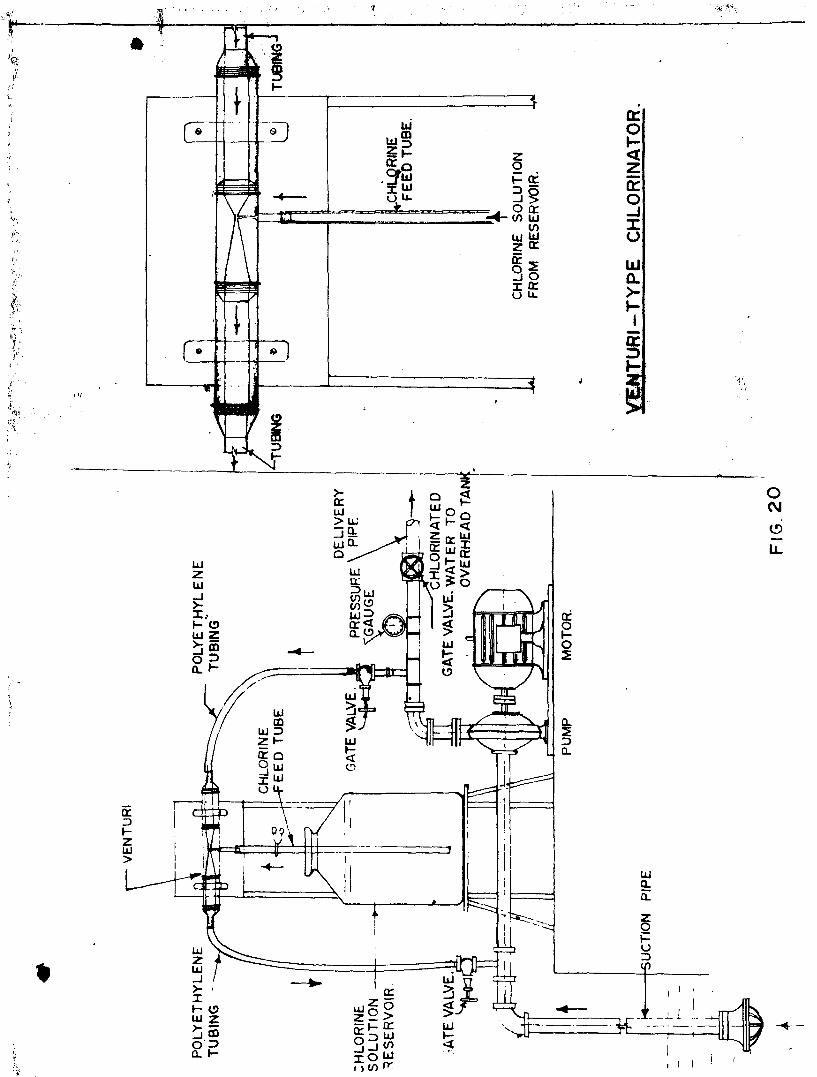
6 .1.1 Venturi-type Chlorinator
A venturi was made out of 4 era thick solid perspex block.
It consisted of a short cylindrical tube of 1.} cm internal
diameter followed by an entrance cone of about 15" angle and a
throat of 3 mm diameter. The throat was followed by a divergent o o
exit cone with an angle of about 5 to 7 . At the throat,

39
perpendicular to it, a small bore was drilled which formed the
inlet port for the bleaching powder solution.
The venturi was inserted in a loop from the delivery to
the suction side of a centrifugal pump fitted on to a shallow
well in the Institute's premises and was tested for its
performance and any operating difficulties. The experimental
set up is shown in Figure 20.
The shallow well was of 2.5 meter diameter with its water
level 3 meters below the top of the well. The depth of water
in the well was 6 meters. A 5 per cent bleachinc powder solution
was used for test purposes.
Prior to putting the venturi in operation, the discharge
rates of the pump at different delivery pressures were measured
and are given in the following Table.
T A B L E X
Delivery pressure Discharge kg/sq cm m /minute
1.056 0.368
0.703 0.473
0.352 0.500
0.0 0.500
During these tests the static suction lift on the pump
varied from 3 meteig in the beginning to 4.2 meteig at the end

I
40
of the t e s t . La te r , t he ven tu r i was commissioned and s tud ied for
i t s minimum discharge r a t e s of b leach ing powder s o l u t i o n by
t h r o t t l i n g the valves on e i t h e r s i de of the ven tu r i but wi thout
t h r o t t l i n g the b leaching powder s o l u t i o n feed t u b e . The
observa t ions a re given in Table XI.
T A B L E XI
FEED RATES OF VENTURI-TYPE CHLORINATOR
Test Condit ions Pump Pump Bleaching Del ivery Discharge powder Pressure s o l u t i o n
feed r a t e kg/sq.cm m /mnt ml/minute
(A) I n l e t t o v e n t u r i
f u l l y open
1 . Out le t from v e n t u r i p a r t l y open 1.056 0.368 250
2 . Out le t from v e n t u r i p a r t l y c losed 1.056 O.368 230
3 . Out le t from v e n t u r i f u r t h e r t h r o t t l e d 1.056 0.266 230
(B) Out le t from v e n t u r i f u l l y open
1 . I n l e t t o v e n t u r i partly closed 1.056 O.368 380
2. Inlet to venturi completely closed I.O56 O.368 380
(C) Inlet to the venturi and outlet from the venturi partly throttled 1.056 O.368 380
(D) Inlet to the venturi and outlet from the venturi partly throttled 0.703 0.473 250

•'a
From the observations given in Table XI, it is apparent
that the dosing rate of bleaching powder solution is mainly
influenced by the suction head on the pump rather than the
suction created by the flov through venturi. In fact, the
:;•.— vir.run bloach.ir.3 powder solution is delivered wiien there is
no flow through the venturi.
With & 5 per cent bleaching powder solution for a pump 3 ^lin •
discharge ra te of cr-45 >n - the -solution feed r a t e has to be in
the range of 30 ml/ram., if o. chlorine dose of 1 ppm is desired
in the water delivered from the pump. If 1 per cent bleaching
powder solution is used the feed rate can be stepped Kp to
150 ral/min. However, the above observations indicated that such
lev; rates were not easy to ad.juot properly unless thei'e was
throttling of the bleaching powder solution feed tube.
With a view to reduce the bleaching powder solution feed
rate, a pinch-cock was Uoed in the solution feed tube. With a
5 per cent bleaching powder solution feed rates of 20, 3>0 and
5C T? /nin. verc tried. At all these rates choking was found
to occur v.'ithin an hour in the solution feed tube below the
pinch-cock due to the f 01 matter, of gas bubbles and the unit
became inoperative. The formation of gas bubbles below the
pinch-cock may be attributed to the release of dissolved
chlorine gar: under the prevalent negative pressure in tie
solution feed tube.
furthermore, the ven;.uri itself was found to suffer
from cho>age difficulties. When the venturi was operated for
a desired feed rat? of bleaching powder solution, it was
observed that the feed rate dropped considerably within a

42
period of 2 hours and complete chokage occurred in about 4
hours. It was found, on examination, that the throat of the
venturi, where the well water mixed with the bleaching powder
solution was choked with the formation of deposits of calcium
carbonate.
Addition of soda ash to bleaching powder in the ratio
of 1 : 5 which was found satisfactory for use in the differential
pressure type chlorinator described later was also tried.
However, this procedure did not very much improve the situation
and choking of the venturi was again observed.
6.1.2 Ejector-type Chlorlnator
Experiments with an imported ejector-type chlorinator
( Figure 21 ) were also found to suffer from the same problem
of drop in feed rate as described above due to formation of
calcium carbonate deposits resulting in eventual chokage of the
unit within a few hours of operation.
6.2 Direct-Feed Device
In the case of venturi-type chlorinator the solution
feed rate is dependent on the suction created at the throat
of the venturi. It is true that the amount of suction at the
throat is governed by the discharge through the venturi when
it is inserted in a rising main. But in the present set up,
where the inlet and outlet of the venturi are connected to the
delivery and suction sides of the pump respectively, the amount
of suction created at the throat of the venturi is greatly

% •:f
RUBBER RINGS.
OUTLET TUBE INLET TUBE
VpRESSUF
" CHLORINE SOLUTION FEED TUBE FROM RESERVOIR.

influenced by the suction head on the pump rather than that
produced due to the flow through the venturi itself, as
described earlier. This is clearly indicated by the fact that
when the inlet to the venturi is fully closed and the outlet
fully open, the maximum suction rate is obtained (See Table XI ).
Though there is no flow of high pressure water through the
venturi, maximum solution feed rate is obtained since the
same sucti^. head that is on the pump is applied at the
throat of the venturi.
This fact indicated the possibility of eliminating the
gadgets described earlier and using a feed system connected
direct to the suction side of the pump.
In further experiments, a direct connection was made
from the bleaching powder solution reservoir to the suction
line of a centrifugal pump ( Figure 22 ). A pinch-cock was
used on the polyethylene tube carrying the chlorine solution
to control the feed rate. This method was found satisfactory
to chlorinate water from wells, .fitted with centrifugal pumps,
as can be seen from the observations recorded in Table XII.
The feed rate was found to remain fairly constant for long
periods.

JL - *
w & • • • •
|V~"
Ltl QL >-h-Q LtJ UJ LL.
1 -V UJ tr Q
rr P < 3
-'••§ - J • -X u
CVJ 1 cvj
o z 19 • •

44
T A B L E XI I
REDUCTION IN FEED RATE WITH TEffi
VENTURI-TYPE CHLCRIMTOR
Feed Rate wi th 1 % Bleaching Powder Solu t ion
Run A+* >. . . Rate of solution sucked in nH/min at different times No. start — "—' ut-
— hr 1 hi? 1 -z hrs 2 hrs 3 hrs 4 hrs 5 hrs
1 133 111 87 40 5 -
2 170 130 90 50 10 -
3 154 143 83 30 2 -
EJECTOR-TYPE CHLORINATOR
Feed Rate with 1 % Bleaching Powder Solution
1 168 140 84 56 28
2 168 140 84 56 42
3 168 168 84 56 28
EJECTOR-TYPE CHB*F. DTATOR
Feed Rate with 1 % Bleaching Powder Solution ( to which soda ash added )
1 168 126 112 84 56
2 168 168 140 112 70 28
3 168 168 140 112 84 28
DIRECT FEED
Feed Rate wi th 1 % Bleaching Powder Solu t ion
1 2 3 4 5 6
168 168 168 168 168 168
168 168 168 168 168 140
168 168 168 140 168 140
168 168 168 140 140 140
168 140 168 l4o 140 140
140 140 140 140 140 140
140 140 140 140 140 140
140 l4o 140 140 140 140

^5
This method of application would be the simplest possible /
aJeinod to use for pumped water supplies for small communities.
Bleaching powder solution of 1 per cent strength would have to
be made up to last at least for one day. Bleaching powder
solution if not allowed to settle properly contains suspended
particles, and thus causes obstruction at the pinch-cock,
resulting in stoppage of the flow. It is, therefore, necessary
that the solution should be clear. The bleaching powder
solution should be allowed to settle for 24 hours and then
carefully withdrawn without disturbing the sludge at the bottom.
It should be filtered through a piece of fine cloth to avoid
larger particles.
The solution container should be of adequate size to
ensure that some solution is left behind at the end of the day's
run to prevent air from entering the pump suction side. Care
must also be taken to shut-off the solution feed line when the
pump is stopped. The rate of chlorine dosing depends on the
quality of the water and has to be adjusted by trial and error
depending upon the chlorine residuals desired.
6.3 Differential Pressure Type Chlorinator
The principle of operation of this unit is based upon the
utilisation of the differential pressure, set up by insertion
of an orifice plate or a venturi tube in the discharge main to
squeeze chlorine solution from a rubber bag and inject it into
the main flow.
The unit consists essentially of a pressure vessel
containing- a loose replaceable rubber bag secured at its neck

46
to the top of the vessel by a rubber lined neck piece, in the
side of whieh a flanged outlet pipe is fitted ( Figure 23 )•
1 top cover plate, which bolts on to the neck piece is provided
with a quick release cover by which the solution is filled into
the feeder. Alternately, when several fillings are required
per day a separate solution preparation vessel can be provided
with a pipe leading to the feeder so that quick recharging can
be effected.
The high pressure water on the upstream side of the
orifice plate connected to the body of the doser squeezes the
rubber bag containing the bleaching powder solution and forces
the solution through the outlet pipe into the main, carrying the
water to be treated. The inlet to, and the outlet from, the doser..
are provided with gate valves. In addition, the outlet tube is
provided with a needle valve to regulate the flow of tha bleaching
powder solution. A drain pipe is incorporated into the body of
the pressure vessel to drain the water while recharging is
carried out.
When bleaching powder solution is added to the water, a
baffled acid proof mixing section is provided for insertion into
the pipe line just after the point where the solution enters the
line. The valves and piping on the outlet side of the doser have
to be of corrosion resistant material.
The performance of such units was studied both in the
Institute and elsewhere ( five installations totally ). These
were found to give satisfactory performance and are suitable for
chlorinating small community water supplies with bleaching powder

"''«/':
UJ X

47
s o l u t i o n c o n s i s t i n g of b leaching powder and soda ash in t h e
r a t i o of 5 : 1 . ( The add i t i on of soda ash he lps t o convert
calcium hypoch lo r i t e i n t o sodium hypoch lo r i t e and reduce
d e p o s i t i o n ) . However, t he rubber bag- needs f requent r e p l a c e
ment, g e n e r a l l y once in 4 t o 8 months. The d i f f e r e n t i a l p r e s su re
type c h l o r i n a t o r s a re commercially marketed in t h i s country and
a re widely used for d i s i n f e c t i o n of water s u p p l i e s . There
should be a minimum of 10 p s i p r e s s u r e in the main l i n e ca r ry ing
water for proper funct ioning of t h e s e u n i t s .
Assuming a b leaching powder s o l u t i o n of 1C00 ppm of
a v a i l a b l e ch lo r ine i s used, t he recharg ing i n t e r v a l for t h e
d i f f e r e n t c a p a c i t i e s of c h l o r i n a t o r s a v a i l a b l e i s given in
Table X I I I .
T A B L E X I I I
RECHARGE INTERVAL FOR DIFFERENT SIZED CHLORINATORS
Population
100
200
5C0
1000
Daily supply at the rate of 50 litres per 'vr.pita
5000
10000
25000
50000
Volume of bleaching powder solution required in liters to give 1 ppm dose
5
10
25
50
Rechs
25 lits.
7
3.5
1.4
0.7
:rge interval (d doser c
70 lits
14
7-0
2.8
1.4
apacity 100 lits.
20
10
4
2
ays of
) with a
140 lits.
28
14
5-6
2.8

48
7 .0 CHIflRINE TEST KIT
Any well water disinfection programme will not be
successful unless we have a simple kit to enable an unskilled
villager to test for the chlorine concentration of the well
waters. The presently available chlorine testing kits in the
market are fairly aimple but expensive costing Rs.10^ - 2.00.
The Institute has fabricated a simple, compact and sturdy
chloroscope from indigenously available materials (see photo ).
The total cost of this unit is Rs. 15/- which i3 within the
reach of rural communities. This will fill the gap for the long-
felt need for a simple and cheap residual chlorine testing kit
for the implementation of the community water supply schemes.
This unit ian detect chlorine concentrations in the range of
0.1 to 1.00 ppm.
The kit consists of the following :
1. Two sample tubes, one for the csntrol and other for test
2. Four standard coloured discs corresponding to 0.1, 0.2, 0.5 anxi 1 mg/l of chlorine
3. An amber coloured orthofolidine reagent dropper
The use of such kits is very well known and needs no
elaboration here.
Standard Colour Discs
Permanent colours corresponding to the standard colours-
for different concentration of chlorine are fixed in gelatin,

P HE R_I C H L- 0 H 0 3 C 0 P E

49
sandwiched between two glass cover-slips and fitted into the
box. Such standard colour discs developed by the Institute
have been found perfectly stable over a period of 2 years now.
They are still under observation for any possible deterioration
of colour with tiim.

50
SUMMARY AND CONCLUSIONS
Various disinfection techniques for small community water
supplies were studied in order to access th^ir performance with
open dug wells as well as piped water supplies. Some of the known
techniques were tried, a few were modified and few entirely new
methods were developed. The disinfectant used in each case was
bleaching powder. Pther disinfectants were not used as they may
not be readily available in all developing countries and were also
not included in the scope of the present study.
The first part of the investigation was confined to a
study of characteristics of bleaching powder in solid and liquid
forms. The essential conclusions were :
1. The available chlorine in bleaching powder manufactured
in India was in the range of j>2 to 35 per cent and the
heat stability tests ( fraction of available chlorine lost
at 10'3 + 2 C in 2 hrs ) revealed that the chlorine loss
was in the range of l/l6 to l/lO. According to the specifica
tions stipulated by the Indian Standards Institution, the
available chlorine should be 33 per cent and the loss of
chlorine in the ' Heat Stability Test ' should not be
more than l/ll.
2. During storage, frequent opening of the bleaching powder
container resulted in a loss of nearly 5 per cent chlorine
in ho days while the loss was 18 per cent if the container
was fully kept open during this period. <;

51
3 . While preparing bleaching powder solution in water,
i t was observed tha t a solution upto 5 per cent
could be made without much loss of chlor ine. Prepara
t ion of stronger solut ions, say 10 per cent and above
resul ted In the l ess of considerable quanti ty of
chlorine.
4. Storage of bleaching powder solution containing nearly
10,000 ppm chlorine did not indicate any s ignif icant
loss of chlorine for 10 days when the containers were
protected from day- l ight . Nearly ho per cent of the
chlorine was los t in the same period when the containers
were exposed t o day- l ight .
The second part of the investigation was concerned
with the use of various types of simple feeding devices for
open dug wells such as earthen pots and drip-type chlor ina tors .
The investigation was further extended to cover feeding
devices which could be used in connection with piped water
supplies for small communities. The various methods were
found to have t he i r pros and cons, which have been
summarised below for ready reference :

52
OScm.dia.
i
SINGLE P?T WITH HOLES IN MIDDLE
One u n i t w i l l c h l o r i n a t e w e l l s
of 9£CO t o 13000 l i t e r s con ten t s
and having a withdrawal r a t e of
900 t o 1300 l i t e r s / d a y ( i . e . ,
se rv ing 40-60 people per day )
Uni t i s f i l l e d wi th 1 ~ kg of
b leaching powder mixed wi th 3 kg
of coarse sand ( 2 mm and above )
covered and suspended 1 meter
below water l e v e l . Needs
r e p l e n i s h i n g every week.
SINGLE POT WITH HOLES AT BOTTOM
One u n i t w i l l c h l o r i n a t e w e l l s
of 9000 t o 13300 l i t e r s con ten t s
and having a withdrawal r a t e of
9CC t o 1300 l i t e r s per day ( i . e . ,
s e rv ing 40-60 pecp le /day ) . More
number of u n i t s may be used for
l a r g e r w e l l s .
Uni t i s f i l l e d wi th 1 - kg of
b leach ing powder mixed wi th 3 kg
of coarse sand as before but wi th
a d d i t i o n of 75 gra of sodium
hexametaphosphate. I t i s then
packed with g rave l up to t h e top and
s u s p e n d e d ! , meter below wafeer l e v e l .
Needs r e p l e n i s h i n g of chemicals
every 2 wool's.

52
DOUBLE POT WITH A HOLE IN EACH POT
One u n i t w i l l c h l o r i n a t e we l l s of
^600 t o 4500 l i t e r s con ten t s and
having a withdrawal r a t e of ~j>60
t o 450 l i t e r s per day ( i . e . ,
s e rv ing 15-20 people per day ) .
The inne r pot i s f i l l e d wi th 1 kg
of b leaching powder wi th 2 kg of
coarse sand ( 2 rnm and above ) and
placed i n s i d e t h e ou te r p o t . The
mouth i s l o o s e l y covered and t h e
u n i t lowered as b e f o r e . Needs
r e p l e n i s h i n g every J> weeks . Idea l
for i n d i v i d u a l household w e l l s .
—LID
FLOAT
GLASS TUBE
POLYETHYLENE TUBE
—STORCOCK GLASS DROPPER
:~WELL WATER
DRIP CHLORINATOR
I t can be used t o d i s i n f e c t a n t
e i t h e r open dug w e l l s or covered
w e l l s , which con ta in 20,000 t o
60,000 l i t e r s wi th a d a i l y w i th
drawal of 2000 t o 6000 l i t e r s ,
( i . e . , se rv ing 80 t o 240 persons )
The u n i t needs r e f i l l i n g a f t e r 2
t o 5 days depending on the consum
p t i o n . 1 % s o l u t i o n of b leaching
powder i s used .

54
GADGET FOR ATTACHMENT TO HAND PUMP
A bleaching powder
solution dispenser for
use with hand purnps was
experimented with but
could not be successfully-
used due to various
reasons such as play in
the pump handle. Hence
further work was
discontinued.
MECHANICAL CLOCK WOWC
AM TISHT COVER
TA11.ET STACK
HOUS4MC
TABLET
CHLORINE AND IODINE TABLET DISPENSER
This device uses a mecha
nical or electrical clock
work mechanism for dropping
stacked tablets, one at a
time, into the well through
a hole at each revolution.
Its initial cost is about
Rs. 100 - 200 per unit and
appears to be more suitable
for household wells in subur
ban areas, where electricity
is available and tablets
can be purchased.
Net recommended for villages
due to possible pilferage.

^ CHLORINE SOLUTION •*• STORAGE TANK
VENTURI AND EJECTOR-TYPE CTIL0RINAT0R5
These chlorinators which
are a v a i l a b l e comraer i a l l y
and sometimes used with
piperl water supp l i e s wore
found t o be u n s a t i s f a c t o r y
owing t o r ap id chokage by
CaCCL. d e p o s i t s a t t h r o a t s .
Hence not recommended. Costs
a re a l s o h igh ranging from
Rs. 8 0 0 / - t o Rs. 1000 / -
per u n i t .
DIRECT-FEED TYPE CHLORINATORS
A simple method of d i s i n f
ec t i on of piped supp l i e s i s
to feed b leaching powder
s o l u t i o n d i r e c t l y in the
suc t ion l i n e of the c e n t r i
fugal pump used for drawing
wa te r . The dose i s ad jus ted
by us ing a pinch-cock on t h e
feed con ta in ing 1 % solut?::- .
in enough q u a n t i t y t o l a s t
1 day and yet l eave a
su rp lus t o prevent a i r fro.-n
e n t e r i n g the suc t i on s i d e .
This method r e q u i r e s no
s p e c i a l gadgets and has been
found s a t i s f a c t o r y in
o p e r a t i o n .

56
DIFFERENTIAL PRESSURE T1YE CHLORINATOR
•ct j'.'.nsai CHLORINE SOLO
B-
PRESSURE WATER i*=4^
This type of chlcrinator
is commercially available
i'or use with piped water
supplies. A solution,
containing bleaching
powder and soda ash in
the proportion of 5 : 1
is filled in a rubber bag
from which it is gradually-
squeezed out in proportion
to the differential
pressure across an orifice
plate. The rate is
adjusted by a needle valve.
This type of chlorinator
though expensive ( R'5.1500
- j50G ; ) is widely used
and found to be quite
satisfactory except for
the need to replace the
rubber bag ( costing about
Rs. 200/- ) every 4 to
6 months.