disk couplings accouplements à disques lamellenkupplungen · les accouplements à disques thomas...
TRANSCRIPT
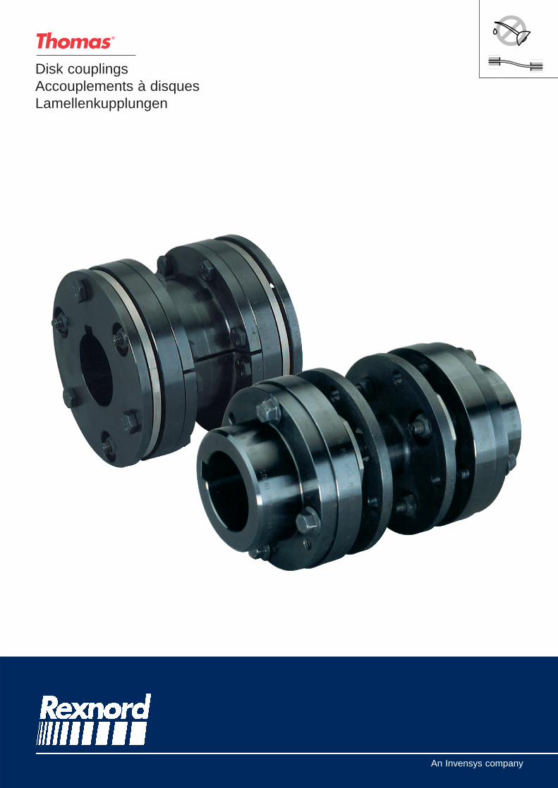
Disk couplingsAccouplements à disquesLamellenkupplungen
An Invensys company

Description Description Beschreibung
89201efd231c
Thomas flexible Disc couplings arenon-lubricated, metal flexing couplings,utilising non-wearing componentsfor the transmission of torque andthe accommodation of unavoidableshaft misalignment. Although thenumber of components may vary toachieve particular functional designattributes, the design base consistsof two hubs, a Centre Member, andtwo Disc Packs with hardware.
Torque Transfer
Connected alternatingly to the driverand driven equipment, bolts attachthe Disc Pack to the major compo-nents (Centre Member, hubs).
During operation, the Disc chordsimmediately behind the bolts fastenedto the driver are tensioned drawingthe driven equipment. Hence,torque transfer is accomplishedwithout moving parts.
Flexibility
Washers axially space the DiscPack from the major components.The Disc Pack bends when theconnected shafts are misaligned toallow angular displacement ofmajor components.
Parallel misalignment is accomo-dated by using a double flexingcoupling; utilizing a centre memberbetween two disk packs.
Conformity
When specified, the models SR71and SR52 couplings can be manu-factured to meet API 610, 8th edi-tion or API 671.
When specified, the model SR54RD coupling can be manufacturedto meet API 610, 7th edition.
If application requires API specifi-cation, please consult supplier.
Les accouplements à disquesThomas sont des accouplementsflexibles métalliques non-lubrifiés uti-lisant des composants sans usurepour la transmission de couple etl'absorption des défauts d'aligne-ment inévitables des arbres. Bienque le nombre des composantspeut varier pour obtenir desconceptions particulières, laconception de base est constituéede deux moyeux, une pièce centra-le et deux paquets de disques avecvisserie.
Transfert du couple
Des vis fixent alternativement lepaquet de disques sur les moyeuxet la pièce centrale connectantainsi la partie entraînante à la partieentraînée.
En fonctionnement, les disquesfixés par les boulons au côtéentraînant, tirent l'équipemententraîné. Ainsi le couple est trans-mis sans mouvement de pièces.
Flexibilité
Des rondelles espacent axiale-ment les paquets de disques desprincipaux composants. Le paquetde disques fléchi pour permettre ledéplacement angulaire des prin-cipaux composants lors d'undéfaut d'alignement des arbresconnectés.
La compensation d’un défaut d'ali-gnement parallèle est rendu pos-sible en utilisant un accouplementdoublement flexible, nécessitantune pièce centrale entre deuxpaquets de disques.
Conformité API
Lorsque cela est demandé, lesmodèles SR71 et SR52 peuventêtre fabriqués pour les conformeraux exigences de l’API 610, 8ème éditionou API 671.
Lorsque cela est demandé, lemodèle SR54 RD peut être fabriquépour se conformer aux exigencesde l’API 610, 7ème édition.
Si l’application demande des spé-cifications API, nous consulter.
Thomas Lamellenkupplungen sindwartungsfreie, flexible Ganz-Metallkupplungen, die verschleißfreizur Übertragung von Drehmomentenund der Neutralisierung unaus-weichlicher Wellen-Ausrichtfehlerdienen. Auch wenn die Anzahl ihrerKomponenten ausführungsspezifischvarieren kann, so bestehen sie inihrem Grundkonzept immer auszwei Naben, einem Mittelstück undzwei verschraubten Lamellenpaketen.
Drehmomentübertragung
Diese erfolgt über die Schrauben,die die Lamellenpakete, in jeweilswechselnder Anordnung, mit demMittelstück, der Antriebs- undAbtriebsnabe verbinden.
Im Betrieb nimmt die mit ihremzugehörigen Lamellenpaket festver-schraubte Antriebsnabe alle nach-folgenden Teile mit, wobei bei derÜbertragung des Drehmomentesverschleißauslösende Reibbewegungengänzlich ausgeschlossen sind.
Flexibilität
Mittels zwischengefügten Scheibenwerden die Lamellenpakete von denangrenzenden Komponenten aufaxialen Abstand gehalten. WinkligeAusrichtfehler der im Kraftflußverbundenen Wellen werden durcheine schadensfreie Verbiegung derLamellenpakete aufgenommen.
Darüberhinaus ist der Ausgleichvon Parallelversatz aufgrund desPrinzips der doppelten Flexibilität,also durch den Einsatz des vonzwei Lamellen-paketen getragenenMittelstückes, gegeben.
API Konformität
Falls erforderlich, können dieBauarten SR71 und SR52 in Über-einstimmung mit den Vorschriftender API 610, 8. Ausgabe, oder derAPI 671 gefertigt werden.
Die Baureihe SR54 RD kann, fallsvorgeschrieben, in Übereinstim-mung mit der API 610, 7. Ausgabe,hergestellt werden.
Sollten anwendungsspezifisch API-Bestimmungen einzuhalten sein, sobitten wir in jedem Fall umRücksprache
2

3
Reference chart Tableau de référence Tabellarische Übersicht
89201efd231c
FEATURES
CARACTÉRISTIQUES
MERKMALE
TN / kg
51 114 114 - 26
1,3%
0,075%
0,06°
3 � 9,7
133 175 78 175 135
2,8%
0,16%
0,11°
89 � 356
1,3%
0,075%
0,06°
102 � 356
1,6%
-
0,11°
-
1,2%
0,1%
0,11°
67 � 494
TN (kNm) 1 000
100
10
1
0,1
Nominal torque
Couple nominal
Nenndrehmoment
SR54 RD-M SR71-M SR52-MSN-MSF-MSV-M
AMR-MCMR-M
�
42 � 195 38 � 264 34 � 257 16 � 203 41 � 394� ��
���
���
yy
yyy
yyy
���
yyy
���
���
��
yyy
yyy
yy �
��
yyy

-
89201efd231c
5
Coding Codification Bezeichnung
1
Size
Model SR54 RD : 162, 200, 225,262, 312, 350, 375, 425, 450, 500,550, 600, 700
Model SR71 : 150, 175, 225, 300,350, 375, 412, 462, 512, 562, 600
Model SR52 : 125, 162, 200, 225,262, 312, 350, 375, 425, 450, 500,550, 600
Model SN, SF, SV : 50, 62, 75,100, 125, 162, 200, 226, 262, 312,350, 375, 425, 450, 500T, 550T,600T, 700T, 750T
Model AMR & CMR : 162, 200,225, 262, 312, 350, 375, 425, 450,500, 550, 600
Taille
Modèle SR54 RD : 162, 200, 225,262, 312, 350, 375, 425, 450, 500,550, 600, 700
Modèle SR71 : 150, 175, 225, 300,350, 375, 412, 462, 512, 562, 600
Modèle SR52 : 125, 162, 200, 225,262, 312, 350, 375, 425, 450, 500,550, 600
Modèle SN, SF, SV : 50, 62, 75,100, 125, 162, 200, 226, 262, 312,350, 375, 425, 450, 500T, 550T,600T, 700T, 750T
Modèle AMR & CMR : 162, 200,225, 262, 312, 350, 375, 425, 450,500, 550, 600
Baugröße
Bauart SR54 RD : 162, 200, 225,262, 312, 350, 375, 425, 450, 500,550, 600, 700
Bauart SR71 : 150, 175, 225, 300,350, 375, 412, 462, 512, 562, 600
Bauart SR52 : 125, 162, 200, 225,262, 312, 350, 375, 425, 450, 500,550, 600
Bauart SN, SF, SV : 50, 62, 75,100, 125, 162, 200, 226, 262, 312,350, 375, 425, 450, 500T, 550T,600T, 700T, 750T
Bauart AMR & CMR : 162, 200,225, 262, 312, 350, 375, 425, 450,500, 550, 600
1
Model
SR54 RD, SR71, SR52, SN, SF,SV, AMR, CMR
Modèle
SR54 RD, SR71, SR52, SN, SF,SV, AMR, CMR
Bauart
SR54 RD, SR71, SR52, SN, SF,SV, AMR, CMR
2
Hubs type (only SR71)No code : standardEH : with counter-bore for threadedextension on a tapered shaftLH : large huborHubs Type (only SR52)LT: standardHT: high torqueorMaterial (only SN, SF & SV)Class A, Class B, Class C, Class D, Class E
Type de moyeux (SR71 seul.)Aucun : standardEH : avec lamage pour fixationaxiale d'arbre coniqueLH : gros moyeuxouType de moyeux (SR52 seul)LT: standardHT: couple élevéouMatière (SN, SF & SV seulement)
Classe A, Classe B, Classe C,Classe D, Classe E
Nabentyp (nur SR71)Ohne : StandardausführungEH : mit Ausdrehung für axialeBefestigung einer konischen WelleLH : große NabeoderNabentyp (nur SR52)LT : standardausfürhungHT : hohes DrehmomentoderWerkstoff (nur SN, SF & SV)Klasse A, Klasse B, Klasse C,Klasse D, Klasse E
4
Distance between shaft ends(only SR71, SR52 & SN, SF, SV)
Distance entre bouts d’arbres(SR71, SR52 & SN, SF, SV seul.)
Wellenabstand (nur SR71, SR52& SN, SF, SV)
5
Bores and keyways specifications
Without specification, keyways asper ISO R773
Spécifications d'alésages et declavetages
Sans spécification, clavetage selonISO R773
Bohrungen und PaßfedernutenHinweise
Ohne Hinweis, Paßfedernut nachISO R773
Example Exemple Beispiel
Thomas coupling size 262, modelSR54 RD, bored standard hubs toø70mm H7 tolerance and ø65mmH7 tolerance with standard key-ways as per ISO R773.
Accouplement Thomas taille 262,modèle SR54 RD, alésage ø70mmtolérance H7 et ø65mm toléranceH7 avec clavetages normalisés sui-vant ISO R773.
Thomas Kupplung, Größe 262,Bauart SR54 RD, Bohrung ø70mmmit H7 Toleranz und Bohrung ø65mit H7 Toleranz, Standard-Paßfedernuten nach ISO R773
6
262 SR54 RD
Unit of measurement
No code : imperial (inch)M : metric version
Unité de mesure
Aucun : impérial (pouce)M : version métrique
Maßeinheit
Ohne : imperial (Zoll)M: metrisch
3
-32 4 5 6
M ø70mm H7/ø65mm H7

Service factorSF Facteur de service Betriebsfaktor
89201efd231c
AGITATORSPure LiquidsVariable density
ALTERNATORBLOWERS
CentrifugalLobeVane
BRIQUETTER MACHINESCAN FILLING MACHINESCANE KNIVESCAR DUMPERSCAR PULLERSCLAY WORKING MACHINERYCOMPRESSORS
CentrifugalLobe, Vane, ScrewsReciprocating - Multi-CylinderAxial
CONVEYORSUniformly loaded or fedHeavy duty - not uniformly fed
CRANES AND HOISTSCRUSHERSDREDGES
Cable ReelsConveyorsCutter Head DrivesJig DrivesManeuvering WinchesPumpsScreen DrivesStackersUtility Winches
ELEVATORSBucketCentrifugal DischargeEscalatorsFreightGravity Discharge
EXTRUDERSPlasticMetal
FANSCentrifugal
Forced Draft (Hostile Environment)Induced Draft (Hostile Environment)
AxialForced Draft (Hostile Environment)Induced Draft (Hostile Environment)
Mine VentilationCooling TowersLight Duty Blower & Fans
FEEDERSLight DutyHeavy Duty
FOOD INDUSTRYBeet SlicerCereal CookerDough MixerMeat GrindersCan Filling MachineBottling
GENERATORSNon-WeldingWelding
HAMMER MILLSLUMBER INDUSTRY
Barkers - Drum TypeEdger Feed - Live RollsLog Haul - InclineLog Haul - Well TypePlaner Feed ChainsPlaner Tilting HoistSlab ConveyorSorting TableTrimmer Feed
MACHINE TOOLSBending RollPlate PlanerPunch Press - Gear DrivenTapping MachinesOther Machines Tools
Main DrivesAuxiliary Drives
METAL MILLSDraw - Bench - CarriageDraw - Bench - Main DriveForming MachinesSlittersTable Conveyor
Non-ReversingReversing
Wire Drawing & Flattening MachineWire Winding Machine
MILLS ROTARY TYPEBallCement KilnsDryers & CoolersKilnsPebble
AGITATEURSLiquides pursDensité variable
ALTERNATEURMACHINES SOUFFLANTES
CentrifugesA lobesA pales
MACHINES DE BRIQUETERIEMACHINES DE MISE EN BOîTECOUPE BAMBOUCOMPACTEURVEHICULE DE REMORQUAGEMACHINES DE TRAVAIL DE L’ARGILECOMPRESSEURS
CentrifugeA lobes, à pales, à visA piston, multicylindreAxial
CONVOYEURSChargé ou alimenté uniformémentService lourd - alimenté non uniformément
LEVAGECONCASSEURSDRAGAGE
Enrouleurs de câbleConvoyeursExcavatricesEntraînement de calibreTreuils de manoeuvrePompesEntraînement de criblesEntasseursTreuil utilitaire
ELEVATEURSA godetsA déchargement centrifugeEscaliers roulantsMonte chargeA déchargement par gravité
EXTRUDEURSMatières plastiquesMatières métalliques
VENTILATEURSCentrifuges
Flux forcé (Environnement hostile)Flux induit (Environnement hostile)
AxialFlux forcé (Environnement hostile)Flux induit (Environnement hostile)
Ventilation de minesTour de réfrigérationVentilateurs peu chargés
ALIMENTATEURSService légerService lourd
INDUSTRIE ALIMENTAIRECoupe betteravesFour à céréalesPétrins, mélangeursHachoirs à viandeMachines de mise en boîteMachines à embouteiller
GENERATRICESNormalesDe soudure
BROYEURS A MARTEAUXINDUSTRIE DU BOIS
Ecorceur type tambourTransporteurs à chainesTransporteur de bûches - InclinéTransporteur de bûches - normalChaînes d’alimentation de raboteusePortique d’inclinaison de rabotageConvoyeur de plaqueTable de triageAlimentation de machine à trancher
MACHINES OUTILCintreuse, plieuseMachine à planerPoinçonneusesMachines à tarauderAutres machines outil
Entraînement principalEntraînement auxiliaire
METALLURGIEBancs à tréfiler - ChargementBancs à tréfiler - Entraînement principalMachine de formageFendoirConvoyeur
Non réversibleRéversible
Machine à tréfiler & à laminer le filBobineuse de fil
BROYEURS ROTATIFSA bouletsFour à cimentSécheurs & RefroidisseursFoursA galets
RÜHRWERKEReine FlüssigkeitFlüssigkeit mit veranderlicher Dichte
GENERATORENGEBLÄSE
ZentrifugalgebläseSchaufelradgebläseFlügelradgebläse
ZIEGELEIMASCHINENKONSERVENMASCHINENZUCKERROHRSCHNEIDERSCHROTTPRESSENZUGMASCHINENLEHMVERARBEITUNGSMASCHINENKOMPRESSOREN
KreiselkompressorenSchaufel-, Flügel-, SchraubenkompressorenMehrzylinder - KolbenkompressorenAxialverdichter
FÖRDERANLAGENGleichmäßige Beladung order Belastung Schwerbetrieb, ungleichmäßige Beladung
KRANE UND HEBEZEUGEBRECHERBAGGERWERKE
KabelwicklerFörderantriebeSchneidkopfantriebeKalibrierantriebeManövrierwindenPumpenSiebantreibeSchüttwerkeAndere Winden
ELEVATORENBecherwerkeMit ZentrifugalentladungRolltreppenLastaufzügeMit Schwerkraftentladung
EXTRUDERFür KunststoffeFür Metalle
GEBLÄSERadialgebläseLuftentwichelnde (Kristische Umgebungseinflüsse)Luftaufnehmende (Kristische Umgebungseinflüsse)AxialgebläseLuftentwichelnde (Kristische Umgebungseinflüsse)Luftaufnehmende (Kristische Umgebungseinflüsse)BergbauventilatorenKühlturmlüferIm Leichtbetrieb
ZUFÜHRER, SPEISEWERKEIm LeichtbetriebIm Schwerbetrieb
NAHRUNGSMITTEL INDUSTRIERübenschneidemaschinenGetreideöfenTeigknetmaschinenFleischmühlenDosenfüllmaschinenFlaschenfüllmaschinen
STROMERZEUGERGleischtromgeneratorenSchweißgeneratoren
HAMMERMÜHLENHOLZINDUSTRIE
EntrindungstrommelnKetten ZufördernScheitholzförderer, schrägsteigendScheitholzförderer, horizontalHobelzuführvorrichtungenHobelbühnen, schräggestelltPlatten und BretterbeförderungenSortiertischeSchneidegatterzuführungen
WERKZEUGMASCHINENBiege und FalzmaschinenHobelmaschinenStanzenGewindeschneidmaschinenAndere WerkzeugmaschinenHauptantriebeNebenantriebe
METALLINDUSTRIEWalzwerke, BeschickungWalzwerke, HauptantriebMaschinen der spanlosen FormgebungSchlitzmaschinenTransportanlagennicht umkehrbarreversierbarDrahtziehbänkeDrahtspulmaschinen
STEINE UND ERDVERARBEITUNGKugelmühlenZementöfenTrockentrommeln, RotationskühlerÖfenKegelbrecher
6
1,0 . . . . . .1,5 . . . . . .1,5 . . . . . .
1,0 . . . . . .1,5 . . . . . .1,5 . . . . . .2,0 . . . . . .1,0 . . . . . .2,0 . . . . . .2,5 . . . . . .1,5 . . . . . .2,0 . . . . . .
1,0 . . . . . .1,5 . . . . . .* . . . . . . .
1,0 . . . . . .
1,5 . . . . . .2,5 . . . . . .2,0 . . . . . .3,0 . . . . . .
2,0 . . . . . .1,5 . . . . . .2,5 . . . . . .2,5 . . . . . .2,0 . . . . . .2,0 . . . . . .2,0 . . . . . .2,0 . . . . . .1,5 . . . . . .
2,0 . . . . . .1,5 . . . . . .1,5 . . . . . .2,0 . . . . . .1,5 . . . . . .
2,0 . . . . . .2,5 . . . . . .
1,5 . . . . . .1,5 . . . . . .
1,5 . . . . . .1,5 . . . . . .2,5 . . . . . .1,5 . . . . . .1,0 . . . . . .
1,5 . . . . . .2,5 . . . . . .
2,0 . . . . . .1,5 . . . . . .2,0 . . . . . .2,0 . . . . . .1,0 . . . . . .1,5 . . . . . .
1,5 . . . . . .3,0 . . . . . .3,0 . . . . . .
2,5 . . . . . .2,0 . . . . . .2,0 . . . . . .2,0 . . . . . .2,0 . . . . . .2,0 . . . . . .1,5 . . . . . .1,5 . . . . . .2,0 . . . . . .
2,0 . . . . . .1,5 . . . . . .2,0 . . . . . .2,5 . . . . . .
1,5 . . . . . .1,5 . . . . . .
2,5 . . . . . .2,5 . . . . . .2,5 . . . . . .2,0 . . . . . .
2,5 . . . . . .3,0 . . . . . .2,0 . . . . . .2,0 . . . . . .
2,5 . . . . . .2,0 . . . . . .2,0 . . . . . .2,0 . . . . . .2,0 . . . . . .

SF
89201efd231c
7
Service factor Facteur de service Betriebsfaktor
A barresTambour désableur
MELANGEURSBétonnièresTambours
PETROCHIMIERéfrigérateursPompe à puits de pétroleFiltres-presses pour paraffineFours rotatifs
PAPETERIEHydraulique auxiliaire d’écorceur Ecorceur mécaniqueTambour écorceur (Engrenage droit seulement)PulpeurBlanchimentCalandresMachine de conversion sauf couteaux, plaqueursCoucheuseCouteaux, plaqueursCylindresSécheurs & refroidisseursRouleaux presseursRouleaux entraîneursTraîne grumePressesDévidoirRouleaux aspirantsLaveurs et épaississeursEnrouleur
IMPRIMERIEREMORQUEURSPOMPES
CentrifugesUsage général (Liquide)AlimentairesRelevage d’eaux uséesDrague
A pistonsDouble effetSimple effet
1 ou 2 cylindres3 cylindres ou plus
A engrenage, à lobes ,à palesINDUSTRIE DU CAOUTCHOUC
MalaxeurCalandreLaminoirsMassicotMachines pour fabrications des pneumatiquesOuverture des presses à pneumatiquesRaidisseurs
CRIBLESFiltre à airRotatif - Pierres ou graviersA circulation d’eauVibratoire
EQUIPEMENT DE TRAITEMENT DES EAUXPOMPES DE TRAITEMENT DES EAUXINDUSTRIE TEXTILE
CalandresCardeusesMachines de finition de l’habillement (Machines àlaver, sécheurs, calandres, etc.)Machines à cannettesSécheursMachines à teinterMétier à tisserEssoreuses à rouleauxMolletoneusesSavonneursFileursMachine à mèchesBobineuses
TREUILS ET GUINDEAUXMACHINE A BOIS
Nota :Consulter le fournisseur
RohrmühlenEntsandungstrommeln
MISCHERBetonmischerMischtrommeln
PETROCHIMIEKühlerÖlförderpumpenParaffinfilterpressenDrehöfen
PAPIERMASCHINENServohydraulik EntrinderEntrinder, mechanische AntriebeEntrindungstrommeln (nur Geradverzahnung)PulpenBleicherKalanderKonvertiermaschinen, ausser GutternGautschenCutterZylinderTrockner und KühlerPresswalzenAntriebswalzenRindenschlepperNaßpressenAbwicklerSaugpressenWäscher und EindickerAufwickler
DRUCKMASCHINENSCHLEPPERPUMPEN
KreiselpumpenÜberhaupt (Leichte Flüssigkeiten)GetränkepumpenAbwasserpumpenBaggergutpumpen
KolbenpumpenDoppeleffekt (Ansaug - Plungerpumpen)Einfacheffekt
1 - oder 2 - Zylinder3 - Zylinder u. mehr
Zahnrad und SchaufelpumpenGUMMIINDUSTRIE
KnetmaschinenKalanderWälzwerkeSchneidwerkeMaschinen für die ReifenerzeugungÖffnung von ReifenpressenSpanner
SIEBELuftfilterTrommelsiebe (Steine oder Kies)WasserumlaufsiebeRüttelsiebe
WASSERAUFBEREITUNGSANLAGENABWASSERPUMPENTEXTILMASCHINEN
KalanderKardenAppretur und Wäschereimaschinen
SchußspulmaschinenTrocknerFärbereimaschinenWebstühleMangelnRäudelmaschinenSeiferSpinnmaschinenFlechtmaschinenAufwickler
WINDWERKEHOLZBEARBEITUNGSMASCHINEN
Notiz:Rückfragen
RodTumbling Barrels
MIXERSConcrete MixersDrum Type
OIL INDUSTRYChillersOil Well PumpingParaffin-Filter-PressRotary Kilns
PAPER MILLSBarker Auxiliaries HydraulicBarker MechanicalBarking Drum (Spur Gear Only)Beater & PulperBleacherCalendersConverting Machines except CuttersCouchCuttersCylindersDryers & CoolersFelt StretcherFelt WhipperLog HaulPressesReelSuction RollWashers and ThickenersWinders
PRINTING PRESSESBARGE HAULPUMPS
CentrifugalGeneral Duty (Liquid)Boiler FeedSlurry (Sewage etc.)Dredge
ReciprocatingDouble ActingSingle Acting
1 or 2 Cylinders3 or more Cylinders
Rotary - Gear, Lobe, VaneRUBBER INDUSTRY
Mixer - BanburyRubber CalendarRubber Mill (2 or more)SheeterTire Building MachinesTire & Tube Press OpenersStrainers
SCREENSAir WashingRotary - Stone or GravelTraveling Water intakeVibratory
SEWAGE DISPOSAL EQUIPMENTSEWAGE TREATMENT PUMPSTEXTILE INDUSTRY
CalendersCard MachinesCloth - Finishing Machines (washers, pads, tenters,dryers, calenders, etc.)Dry CansDryersDyeing MachineryLoomsManglesNappersSoapersSpinnersTenter - FramesWinders (other than Batchers)
WINDLASSWOODWORKING MACHINERY
Note :Consult supplier
2,0 . . . . . .2,0 . . . . . .
2,0 . . . . . .2,0 . . . . . .
1,5 . . . . . .2,0 . . . . . .2,0 . . . . . .2,0 . . . . . .
2,5 . . . . . .2,5 . . . . . .2,5 . . . . . .2,0 . . . . . .1,0 . . . . . .2,0 . . . . . .1,5 . . . . . .2,0 . . . . . .2,0 . . . . . .2,0 . . . . . .2,0 . . . . . .1,5 . . . . . .2,0 . . . . . .2,0 . . . . . .2,0 . . . . . .1,5 . . . . . .2,0 . . . . . .1,5 . . . . . .1,5 . . . . . .1,5 . . . . . .2,0 . . . . . .
1,0 . . . . . .1,0 . . . . . .1,5 . . . . . .2,0 . . . . . .
2,0 . . . . . .
2,5 . . . . . .2,0 . . . . . .1,5 . . . . . .
3,0 . . . . . .2,0 . . . . . .2,5 . . . . . .2,0 . . . . . .2,5 . . . . . .1,0 . . . . . .2,0 . . . . . .
1,0 . . . . . .1,5 . . . . . .1,5 . . . . . .2,5 . . . . . .1,5 . . . . . .1,5 . . . . . .
2,0 . . . . . .1,5 . . . . . .1,5 . . . . . .
2,0 . . . . . .1,5 . . . . . .1,5 . . . . . .1,5 . . . . . .1,5 . . . . . .1,5 . . . . . .1,5 . . . . . .1,5 . . . . . .1,5 . . . . . .1,5 . . . . . .2,0 . . . . . .1,5 . . . . . .
* . . . . . . .
DescriptionSR54 RD-M Description Beschreibung
89201efd231c
The maintenance free SR54 RD isspecifically designed as a replace-ment for close-coupled, lubricatedgear and grid couplings whereshaft space is minimal.
For ease of mounting, this modelfeatures an axially split centermember that permits the removalof disc packs without moving theconnected equipment.
The SR54 RD can be manufactu-red to meet API610 7th Edition.
L’accouplement sans entretienSR54 RD est spécifiquement conçupour le remplacement des accou-plements lubrifiés à denture et àressort où la distance entre lesarbres est minimale.
Pour faciliter le montage, ce modèlepossède un élément central endeux parties radiales permettant leremplacement des paquets dedisques sans déplacer lesmachines connectées.
Le SR54 RD peut être fabriquépour être en conformité avec API610 7ème édition.
Die wartungsfreie SR54 wurde spe-ziell entworfen als Ersatz für ges-chmierte Zahn- undFederkupplungen mit einem mini-malen Abstand zwischen denWellen.
Im Hinblick auf eine einfacheMontage weist dieses Modell einaxial geteiltes Mittelelement auf, sodaß sich die Lamellenpakete radialentfernen lassen, ohne dieangeschlossenen Maschinen zubewegen.
Die SR54 RD kann so gefertigtwerden, daß sie der API 610, 7.Ausgabe, entspricht.
Materials Matières Werkstoffe
Hubs and Center Member
Roll forged steel.Alloy and stainless steel availableon special order.
Hardware
Alloy steel (Zinc or cadmium platedavailable).
Disc Packs
300-series stainless steel.
Moyeux et élément central
Acier forgé.
Acier allié et inoxydable disponiblesur demande spéciale.
Visserie
Acier allié (Plaquage de zinc ou decadmium disponible).
Paquets de disques
Serie 300 : Acier inoxydable standard
Naben und Mittelelement
Walzgeschmiedeter Stahl
Legierungsstahl und rostfreier Stahlauf Wunsch lieferbar.
Kleinteile
Legierungsstahl (verzinkt oderverkadmiert lieferbar)
Lamellenpakete
Rostfreier Stahl serie 300
Typical applications Applications typiques Typische Anwendungen
Closed-coupled applications.Suitable as replacement for gearand grid couplings
Applications à bouts d’arbres rap-prochés. Recommandé pour leremplacement des accouplementsà denture et à ressort.
Anwendungen mit eng zusammen-liegenden Wellenzapfen.Empfohlen als Ersatz für Zahn- undFederkupplungen.
8

Metrische AusführungVersion métriqueMetric version
162 700
M
89201efd231c
9
C
C
F
FE
M
The user is responsiblefor the provision of safetyguards and correct ins-tallation of all equipment.
Certified dimensionsavailable upon request.
Les dispositifs deprotection doivent êtreprévus par l'utilisateur.Celui-ci est responsablede l'installation correctede l'ensemble.
Dimensions définitivessur demande.
Der Benutzer istverantwortlich für dieBeistellung derSchutzhauben und dasfachgemäße Aufstellender gesamten Ausrüstung.
Verbindliche Maße aufWunsch.
D1 D1
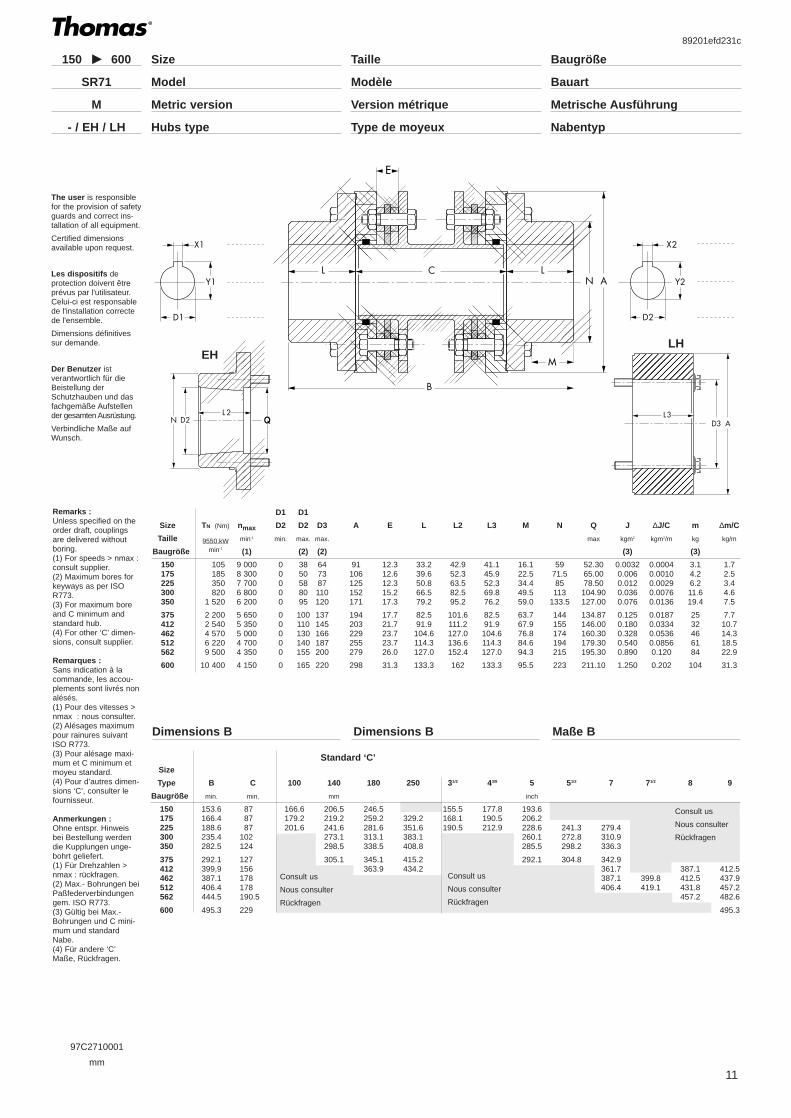
Size TN (Nm) nmax D2 D2 A B1 C1 E F1 L M N J m
Taille 9550.kW min-1 min. max. kgm2 kg
Baugröße min-1 (1) (2) (3) (3)
162 490 4 200 0 42 110 107,5 3,0 7,4 98,5 47,7 34,0 59,5 0,0071 4,4200 920 3 800 0 60 138 122,0 3,0 9,1 110,7 53,8 40,2 82,5 0,0206 7,9225 1 210 3 700 0 65 145 125,5 3,0 9,1 114,3 55,6 53,8 89 0,0255 8,9262 1 520 3 600 0 75 168 149,0 4,8 11,9 136,4 65,8 57,6 105 0,0556 14,4312 2 750 3 000 0 90 198 163,0 4,8 12,7 149,1 72,1 67,8 127 0,117 21,5
350 3 850 2 800 0 100 221 189,0 6,4 13,7 172,9 83,3 74,7 140 0,207 31375 5 800 2 500 0 110 246 205,0 6,4 15,0 187,2 90,4 78,0 154 0,363 43425 8 200 2 300 0 120 267 228,0 6,4 15,7 208,0 100,8 81,8 167 0,562 57450 9 300 2 200 0 130 287 260,5 7,9 18,0 236,4 114,3 85,9 178 0,849 75500 14 000 2 000 0 140 327 274,0 7,9 19,8 247,6 119,9 94,8 200 1,59 109
550 24 300 1 900 0 150 367 308,0 9,7 23,1 279,4 134,8 117,3 222 2,87 157600 30 400 1 800 0 170 406 349,0 9,7 24,9 314,4 152,4 127,2 236 4,83 217700 39 100 1 700 0 195 464 404,0 9,7 30,2 365,3 177,8 129,2 276 9,33 323
D1 D1
Size TN (Nm) nmax D2 D2 A B2 C2 E F2 L M N J m
Taille 9550.kW min-1 min. max. kgm2 kg
Baugröße min-1 (1) (2) (3) (3)
162 490 4 200 0 42 110 145 44,9 7,4 140,4 47,8 34,0 59,45 0,0071 4,4200 920 3 800 0 60 138 163 49,8 9,1 157,4 53,8 40,2 82,55 0,0206 7,9225 1 210 3 700 0 65 145 168 51,5 9,1 162,8 55,6 53,8 88,9 0,0255 8,9262 1 520 3 600 0 75 168 200 61,4 11,9 193 65,8 57,6 104,65 0,0556 14,4312 2 750 3 000 0 90 198 218 66,5 12,7 210,8 72,1 67,8 127,00 0,117 21,5
350 3 850 2 800 0 100 221 252 77,7 13,7 244,2 83,3 74,7 139,70 0,207 31375 5 800 2 500 0 110 246 273 82,8 15,0 263,6 90,4 78,0 153,90 0,363 43425 8 200 2 300 0 120 267 303 91,6 15,7 293,3 100,8 81,8 166,60 0,562 57450 9 300 2 200 0 130 287 346 105,4 18,0 333,9 114,3 85,9 177,80 0,849 75500 14 000 2 000 0 140 327 361 108,2 19,8 347,9 119,9 94,8 200,15 1,59 109550 24 300 1 900 0 150 367 406 122,1 23,1 391,9 134,9 117,3 222,25 2,87 157600 30 400 1 800 0 170 406 459 136,9 24,9 441,9 152,4 127,2 236,45 4,83 217700 39 100 1 700 0 195 464 552 158,0 30,2 513,6 177,8 129,2 276,35 9,33 323
Remarks :Unless specified on theorder draft, couplingsare delivered withoutboring.(1) For speeds > nmax :consult supplier.(2) Maximum bores forkeyways as per ISOR773.(3) For maximum bore.
Remarques :Sans indication à lacommande, les accou-plements sont livrés nonalésés.(1) Pour des vitesses >nmax : nous consulter.(2) Alésages maximumpour rainures suivantISO R773.(3) Pour alésage maxi-mum.
Anmerkungen :Ohne entspr. Hinweisbei Bestellung werdendie Kupplungen unge-bohrt geliefert.(1) Für Drehzahlen >nmax : rückfragen.(2) Max.- Bohrungen beiPaßfederverbindungengem. ISO R773.(3) Gültig bei Max.-Bohrungen.
97C254RD01
mm
Baugröße
Bauart
Taille
Modèle
Size
ModelSR54 RD
�
�
�
�
DescriptionSR71-M Description Beschreibung
89201efd231c
The SR71 used for spacer-typeapplication is designed for ease ofmaintenance by featuring a drop-out center member that avoidsmoving the connected equipment.
Consisting of a simple three piecedesign, two hubs are pilot fit to afactory assembled center member.
The piloting provides repeatableassembly of components for betterdynamic balance characteristics.
On request the SR 71 can be exe-cuted to meet API 671 and/or API610 8ed. It can also be manufactu-red to conform with various non-sparking requirements.
Utilisé pour les applications deman-dant un espace entre les boutsd’arbres, le SR71 est conçu pourfaciliter la maintenance grâce à unélément central amovible évitant ledéplacement des machinesconnectées.
Il est essentiellement constitué detrois parties distinctes. Deuxmoyeux sont montés centrés surun élément central assemblé enusine.
Le centrage permet des assem-blages répétitifs des composantstout en conservant l’équilibrage.
Le SR 71 peut se conformer à lanorme API 671 et/ou API 610 8edsur demande. Une version à risqueréduit d’étincelles, en conditionsnormales de fonctionnement, peutégalement être fournie.
Materials Matières Werkstoffe
Hub and center member
Carbon steel.
Hardware and capscreews
High strength alloy steel
Disc packs
300-series stainless steel.
Moyeux et élément central
Acier allié.
Visserie
Acier fortement allié
Paquets de disques
Acier réfractaire inoxydable.
Naben und Mittelelement
Kohlenstoffstahl
Kleinteile
Hochlegierter Stahl
Lamellenpackete
Rostfreier, hitzebeständiger Stahl
10
Typical applications Applications typiques Typische Anwendungen
Pumps and compressors withpopular shaft separation standards.Blowers, fans, speed increasers.
Pompes et compresseurs avecdistances entre bouts d’arbresstandard. Souffleurs, ventilateurs,multiplicateurs de vitesse.
Pumpen und Kompressoren mitStandardabstand zwischen denWellenzapfen. Gebläse,Ventilatoren, Übersetzungsgetriebe.
Die Kupplung SR71 eignet sich fürAnwendungen, bei denen einAbstand zwischen denWellenzapfen erforderlich ist. Sieist wartungsfreundlich dank einesabnehmbaren Mittelelementes, sodaß angeschlossene Maschinennicht bewegt werden müssen.
Sie besteht aus drei Teilen : zweiNaben sind zentriert auf einen imWerk zusammengebautenMitteleinheit montiert.
Der zentrierte Einbau ermöglichtein wiederholtes Zusammenbauender Teile unter Wahrung der dyna-mischen Auswuchtung.
Die SR71 kann entsprechernd derAPI 671 und/oder API 610, 8.Ausgabe auf Anfrage geliefert wer-den. Funkenfreie bzw.-reduzierte Ausführung auch liefer-bar
97C2710001
mm
BauartModèleModelSR71
89201efd231c
11
E
M
The user is responsiblefor the provision of safetyguards and correct ins-tallation of all equipment.
Certified dimensionsavailable upon request.
Les dispositifs deprotection doivent êtreprévus par l'utilisateur.Celui-ci est responsablede l'installation correctede l'ensemble.
Dimensions définitivessur demande.
Der Benutzer istverantwortlich für dieBeistellung derSchutzhauben und dasfachgemäße Aufstellender gesamten Ausrüstung.
Verbindliche Maße aufWunsch.
D1 D1
Size TN (Nm) nmax D2 D2 D3 A E L L2 L3 M N Q J ∆J/C m ∆m/C
Taille 9550.kW min-1 min. max. max. max kgm2 kgm2/m kg kg/m
Baugröße min-1 (1) (2) (2) (3) (3)
150 105 9 000 0 38 64 91 12.3 33.2 42.9 41.1 16.1 59 52.30 0.0032 0.0004 3.1 1.7175 185 8 300 0 50 73 106 12.6 39.6 52.3 45.9 22.5 71.5 65.00 0.006 0.0010 4.2 2.5225 350 7 700 0 58 87 125 12.3 50.8 63.5 52.3 34.4 85 78.50 0.012 0.0029 6.2 3.4300 820 6 800 0 80 110 152 15.2 66.5 82.5 69.8 49.5 113 104.90 0.036 0.0076 11.6 4.6350 1 520 6 200 0 95 120 171 17.3 79.2 95.2 76.2 59.0 133.5 127.00 0.076 0.0136 19.4 7.5
375 2 200 5 650 0 100 137 194 17.7 82.5 101.6 82.5 63.7 144 134.87 0.125 0.0187 25 7.7412 2 540 5 350 0 110 145 203 21.7 91.9 111.2 91.9 67.9 155 146.00 0.180 0.0334 32 10.7462 4 570 5 000 0 130 166 229 23.7 104.6 127.0 104.6 76.8 174 160.30 0.328 0.0536 46 14.3512 6 220 4 700 0 140 187 255 23.7 114.3 136.6 114.3 84.6 194 179.30 0.540 0.0856 61 18.5562 9 500 4 350 0 155 200 279 26.0 127.0 152.4 127.0 94.3 215 195.30 0.890 0.120 84 22.9
600 10 400 4 150 0 165 220 298 31.3 133.3 162 133.3 95.5 223 211.10 1.250 0.202 104 31.3
Remarks :Unless specified on theorder draft, couplingsare delivered withoutboring.(1) For speeds > nmax :consult supplier.(2) Maximum bores forkeyways as per ISOR773.(3) For maximum boreand C minimum andstandard hub.(4) For other ‘C’ dimen-sions, consult supplier.
Remarques :Sans indication à lacommande, les accou-plements sont livrés nonalésés.(1) Pour des vitesses >nmax : nous consulter.(2) Alésages maximumpour rainures suivantISO R773.(3) Pour alésage maxi-mum et C minimum etmoyeu standard.(4) Pour d’autres dimen-sions ‘C’, consulter lefournisseur.
Anmerkungen :Ohne entspr. Hinweisbei Bestellung werdendie Kupplungen unge-bohrt geliefert.(1) Für Drehzahlen >nmax : rückfragen.(2) Max.- Bohrungen beiPaßfederverbindungengem. ISO R773.(3) Gültig bei Max.-Bohrungen und C mini-mum und standardNabe.(4) Für andere ‘C’Maße, Rückfragen.
BaugrößeTailleSize150 600
�
�
�
�
Q
��
����
������
��������
����������
�����������
�����������
�����������
�����������
�����������
����������
��������
������
����
��
�
���
�����
�������
���������
�����������
�����������
�����������
�����������
�����������
�����������
���������
�������
�����
���
�
Size
Type B C 100 140 180 250 31/2 43/8 5 51/2 7 71/2 8 9
Baugröße min. min. mm inch
150 153.6 87 166.6 206.5 246.5 155.5 177.8 193.6175 166.4 87 179.2 219.2 259.2 329.2 168.1 190.5 206.2225 188.6 87 201.6 241.6 281.6 351.6 190.5 212.9 228.6 241.3 279.4300 235.4 102 273.1 313.1 383.1 260.1 272.8 310.9350 282.5 124 298.5 338.5 408.8 285.5 298.2 336.3
375 292.1 127 305.1 345.1 415.2 292.1 304.8 342.9412 399,9 156 363.9 434.2 361.7 387.1 412.5462 387.1 178 387.1 399.8 412.5 437.9512 406.4 178 406.4 419.1 431.8 457.2562 444.5 190.5 457.2 482.6
600 495.3 229 495.3
Standard ‘C’
Metrische AusführungVersion métriqueMetric versionM
NabentypType de moyeuxHubs type- / EH / LH
EHLH
Dimensions B Dimensions B Maße B
Consult us
Nous consulter
Rückfragen
Consult us
Nous consulter
Rückfragen
Consult us
Nous consulter
Rückfragen

DescriptionSR52-M Description Beschreibung
89201efd231c
The SR52 is a high-speed, hightorque coupling used where mini-mum coupling weight is desirable.
It has just three components ; twohubs and a machined, flanged cen-ter member.
Design modifications can be madeto further reduce the couplingweight, making the SR 52 an eco-nomical solution for drives requiringlight weight without the higher desi-gn, materials and manufacturingcosts of high performance cou-plings.
Le SR52 est un accouplement àgrande vitesse et fort couple utilisélorsqu’une faible masse d’accou-plement est désirée.
Il est composé de trois parties :Deux moyeux et un élément centralà bride entièrement usiné.
Des modification de conceptionpeuvent être réalisées afin deréduire la masse de l’accouplementfaisant du SR52 une solution éco-nomique pour les systèmesdemandant une faible masse sansexiger la conception de haute tech-nologie, les matériaux et les coûtsde fabrication des accouplementsde hautes performances.
Die SR52 ist eine Kupplung fürhohe Drehzahl und Drehmomente,die sich für Anwendungen eignet,bei denen ein geringesKupplungsgewicht wünschenswertist.
Sie umfaßt drei Teile : zwei Nabenund ein Mittelelement mit vollstän-dig maschinell bearbeitetemFlansch.
Änderungen der Bauweise sindmöglich, um das Gewicht derKupplung weiter zu verringern; aufdiese Weise stellt die SR52 einewirtschaftliche Lösung dar fürAntriebssysteme, die ein geringesGewicht erfordern, ohne dabei dieHigh-tech-Bauweise sowie dieWerkstoffe und Herstellungskostenvon Hochleistungskupplungen zuverlangen.
12
Materials Matières Werkstoffe
Hubs and Center Member
Roll forged steel.Alloy and stainless steel availableon special order.
Hardware
Alloy steel (Zinc or cadmium platedavailable).
Disc Packs
300-series stainless steel standard.Other materials (Monel, Inconel,Tomaloy, etc.) available on request.
Moyeux et élément central
Acier forgé.
Acier allié et inoxydable disponiblesur demande spéciale.
Visserie
Acier allié (Plaquage de zinc ou decadmium disponible).
Paquets de disques
Aciers Inoxydables Série 300standard.Autres matériaux (Monel, Inconel,Tomaloy, etc.) disponible surdemande.
Naben und Mittelelement
Walzgeschmiedeter Stahl
Legierungsstahl und rostfreier Stahlauf besondere Anfrage lieferbar.
Kleinteile
Legierungsstahl (verzinkt oder ver-kadmiert lieferbar)
Lamellenpakete
Rostfreier Stahl Serie 300standard.Andere Werkstoffe (Monel, Inconel,Tomaloy, usw..) auf Anfrage liefer-bar.
Typical applications Applications typiques Typische Anwendungen
Pumps and compressors(Centrifugal, rotary, lobe and axial),speed increasers, fans, dynamo-meters.
Pompes et compresseurs(Centrifuges, rotatifs, à lobe etaxiaux), multiplicateurs de vitesse,ventilateurs, dynamomètres.
Pumpen und Kompressoren(Zentrifugal-, Dreh-, Lamellen- undAxial-) , Übersetzungsgetriebe,Ventilatoren, Dynamometer.

89201efd231c
13
97C2520001
mm
M
D1 D1Size TN (Nm) nmax nmax D2 D2 A E L M N J ∆J/C m ∆m/CTaille 9550.kW min-1 min-1 min. max. kgm2 kgm2/m kg kg/m
Baugröße min-1 (1) (2) (3) (3) (3) (3)
125 150 5 000 15 000 0 38 94 6,7 33,3 16.5 52,4 0,0020 0,0017 2,0 2,8162 300 4 600 15 000 0 50 110 7,1 44,5 28,1 70,0 0,0043 0,0031 3,4 3,7200 600 4 250 15 000 0 60 138 9,1 52,4 34,2 83,3 0,0129 0,0067 5,9 4,5225 1 000 4 100 14 000 0 70 144 9,1 66,7 48,5 96,0 0,0187 0,0075 7,7 4,7262 2 000 3 900 13 000 0 85 168 11,9 73,0 50,8 114,0 0,0421 0,0153 12,7 7,2
312 3 000 3 450 11 700 0 95 198 12,7 85,7 61,1 135,0 0,0919 0,0268 19,5 8,7350 5 000 3 200 10 500 0 110 221 13,5 95,3 65,9 150,0 0,1644 0,0371 27,7 9,7375 10 000 3 000 9 400 0 120 246 15,1 101,6 68,9 165,0 0,2750 0,0611 38,1 13,3425 12 000 2 800 8 700 0 130 267 15,9 108,0 71,6 178,0 0,4155 0,0944 48,5 17,3450 15 000 2 700 8 100 0 140 287 18,3 114,0 74,4 189,0 0,591 0,1138 60 18,4
500 20 000 2 500 7 100 0 145 327 19,8 127,0 83,3 213,0 1,115 0,198 87 24,5550 27 500 2 300 6 300 0 170 367 23,0 140,0 89,9 240,0 2,042 0,3821 124 38,7600 38 000 2 150 5 700 0 190 406 24,6 152,0 95,6 260,0 3,336 0,5253 167 43,0
The user is responsiblefor the provision of safetyguards and correct ins-tallation of all equipment.
Certified dimensionsavailable upon request.
Les dispositifs deprotection doivent êtreprévus par l'utilisateur.Celui-ci est responsablede l'installation correctede l'ensemble.
Dimensions définitivessur demande.
Der Benutzer istverantwortlich für dieBeistellung derSchutzhauben und dasfachgemäße Aufstellender gesamten Ausrüstung.
Verbindliche Maße aufWunsch.
Remarks :Unless specified on theorder draft, couplings aredelivered without boring.(1) Max. speed withbalancing.(2) Maximum bores forkeyways as per ISOR773.(3) For maximum boreand C minimum.
Remarques :Sans indication à la com-mande, les accouple-ments sont livrés nonalésés.(1) Vitesse maxi. avecéquilibrage.(2) Alésages maximumpour rainures suivantISO R773.(3) Pour alésage maxi-mum et C minimum.
Anmerkungen :Ohne entspr. Hinweis beiBestellung werden dieKupplungen ungebohrtgeliefert.(1) Max. Drehzahl mitAuswuchtung.(2) Max.- Bohrungen beiPaßfederverbindungengem. ISO R773.(3) Gültig bei Max.-Bohrungen und C mini-mum.
BaugrößeTailleSize125 925
�
�
�
�
BauartModèleModelSR52
Metrische AusführungVersion métriqueMetric versionM
SizeType B (LT) C 100 140 180 250 31/2 4 5 51/2 6 7 8 9 10
Baugröbe min min mm inch
125 - - 166.6 168.2162 141.0 52.0 189.0 229.0 216.0200 171.8 67.0 204.8 244.8 231.8225 203.4 70.0 233.4 273.4 313.4 260.4 311.2262 228.0 82.0 286.0 326.0 273.0 323.8
312 267.4 96.0 311.4 351.4 311.1 349.2350 296.6 106.0 370.6 440,6 343.0 368.4375 320.2 117.0 383.2 453,2 381.0425 342.0 126.0 396,0 466,0 393.8450 364.0 136.0 408,0 478.0 405.8 431.2
500 408.0 154.0 434,0 504,0 482.6550 455.0 175.0 530,0 534.0600 495.0 191.0 554,0 558.0
Dimensions B Dimensions B Maße B
Consult us
Nous consulter
Rückfragen
Consult us
Nous consulter
Rückfragen
Consult us
Nous consulter
Rückfragen
D1 D1Size TN (Nm) nmax nmax D2 D2 A E L M N J ∆J/C m ∆m/CTaille 9550.kW min-1 min-1 min. max. kgm2 kgm2/m kg kg/m
Baugröße min-1 (1) (2) (3) (3) (3) (3)
125 300 5 000 15 000 0 38 94 6,7 45 16.5 52,4 0,0021 0,0017 2,2 2,8162 600 4 600 15 000 0 50 110 7,1 55 28,1 70,0 0,0021 0,0031 3,5 3,7200 1 180 4 250 15 000 0 60 138 9,1 70 34,2 83,3 0,0095 0,0067 6,4 4,5225 1 670 4 100 14 000 0 70 144 9,1 75 48,5 96,0 0,0150 0,0075 7,9 4,7262 2 960 3 900 13 000 0 85 168 11,9 85 50,8 114,0 0,0366 0,0153 13,3 7,2
312 4 100 3 450 11 700 0 95 198 12,7 110 61,1 135,0 0,0890 0,0268 21,3 8,7350 6 680 3 200 10 500 0 110 221 13,5 120 65,9 150,0 0,1612 0,0371 31,0 9,7375 10 200 3 000 9 400 0 120 246 15,1 140 68,9 165,0 0,2681 0,0611 43,9 13,3425 13 300 2 800 8 700 0 130 267 15,9 150 71,6 178,0 0,3856 0,0944 56,6 17,3450 17 000 2 700 8 100 0 140 287 18,3 160 74,4 189,0 0,5755 0,1138 69,5 18,4
500 26 000 2 500 7 100 0 145 327 19,8 180 83,3 213,0 1,0757 0,198 100 24,5550 36 500 2 300 6 300 0 170 367 23,0 190 89,9 240,0 1,9003 0,3821 139 38,7600 46 000 2 150 5 700 0 190 406 24,6 200 95,6 260,0 3,2249 0,5253 183 43,0
Hubs HT Moyeux HT Nabe HT
Hubs LT Moyeux LT Nabe LT
DescriptionSN-MSF-MSV-M
Description Beschreibung
89201efd231c
The SN coupling, in any of itsvarious configurations, is designedto span long distances to transmitpower into areas where temperature,moisture, dust or corrosive conditionswould adversely affect the drivingmachinery.
For models SN and SV, a floatingcenter flanged tube is used to reduceweight.
These models also eliminate theneed for intermediate support bearingswhen the connected shafts arerigidly supported.
The SF model has a stub shaft onone end intended to pass through asupport bearing and connect withanother SN coupling in order tospan extra long distances.
Dans chacune de ses différentesconfigurations, l’accouplement SNest conçu pour transmettre unepuissance entre deux arbres trésdistants dans un environnement oùla température, l’humidité la pous-sière ou des conditions corrosivesaffecteraient de façon irrémédiablela machine entraînante.
Pour les modèles SN et SV, untube flottant central à bride est utili-sé pour réduire la masse.
Ces modèles éliminent égalementl’utilisation de palier intermédiairelorsque les arbres connectés sontsupportés rigidement.
Une des extrémités du modèle SFest composé d’un arbre sortantpermettant la mise en place d’unpalier et la connection avec unautre accouplement SN dans le butde réaliser d’extra longues dis-tances.
Die SN-Kupplungen sind in ihrenverschiedenen Konfigurationendarauf ausgelegt, Kraftübertragungenüber längere Abstände in Bereichezu führen, wo Temperatur,Feuchtigkeit, Staub oder korrosions-fördernde Bedingungen dieAntriebsgeräte unwiderruflich be-schädigen würden.
Bei den Modellen SN und SV wirdeine Mitteleinteil aus Rohr verwen-det, um das Gewicht zu verringern.
Diese Modelle machen haufigZwischenlager überflüssig.
Das SF-Modell weist an einemEnde eine Flanschwelle auf, diedurch ein Trägerlager geführt undmit einer weiteren SN-Kupplungverbunden werden kann, umbesonders weite Abstände zu über-brücken.
Materials Matières Werkstoffe
Disc pack
Stainless steel
Hardware, hubs and centermember
Class A : All steel
Class B : All steel - Zinc plated
Class C : Hardware stainless steel,hubs and center member zincplated
Class D : Stainless steel except forzinc plated hubs
Class E : All stainless steel (300series stainless steel)
Paquet de disques
Acier inoxydable
Visserie, moyeux et élémentcentral
Classe A : Tout acier
Classe B : Tout acier zingué
Classe C : Visserie en acier inoxy-dable, moyeux et élément centralen acier zingué.
Classe D : Tout acier inoxydablesauf moyeux en acier zingué
Classe E : Tout acier inoxydable(Série 300)
Lamellenpaket
Rostfreier Stahl
Kleinteile, Naben undMittelelement
Klasse A : Ganzstahl
Klasse B : Ganzstahl, verzinkt
Klasse C : Kleinteile aus rostfreiemStahl, Naben und Mittelelementverzinkt
Klasse D : Rostfreier Stahl, mitAusnahme der Naben aus verzink-tem Stahl
Klasse E : Ganzstahl, rostfrei(Serie 300)
14
Typical applications Applications typiques Typische Anwendungen
Turbines, pumps, compressors,test stands, generators, speedincreasers, Fans (Cooling tower,mine ventilating, Forced and indu-ced draft), paper mill drives, lineshafts, printing machines.
Turbines, pompes, compresseurs,bancs d’essais, génératrices, multi-plicateurs de vitesse, ventilateurs(Tours de réfrigération, ventilationde mines, à flux forcé et induit),machines à papier, lignes d’arbre,presses d’impression.
Turbinen, Pumpen, Kompressoren,Prüfstände, Generatoren, Überset-zungsgetriebe, Ventilatoren(Kühltürme, Belüftung von Gruben,mit Zwangs- und Induktionszug),Antrieb von Papiermühlen,Transmissionswellen,Druckmaschinen.
97C2SN0001
mm
The user is responsiblefor the provision of safetyguards and correct ins-tallation of all equipment.
Certified dimensionsavailable upon request.
Les dispositifs deprotection doivent êtreprévus par l'utilisateur.Celui-ci est responsablede l'installation correctede l'ensemble.
Dimensions définitivessur demande.
Der Benutzer istverantwortlich für dieBeistellung derSchutzhauben und dasfachgemäße Aufstellender gesamten Ausrüstung.
Verbindliche Maße aufWunsch.
D1 D1
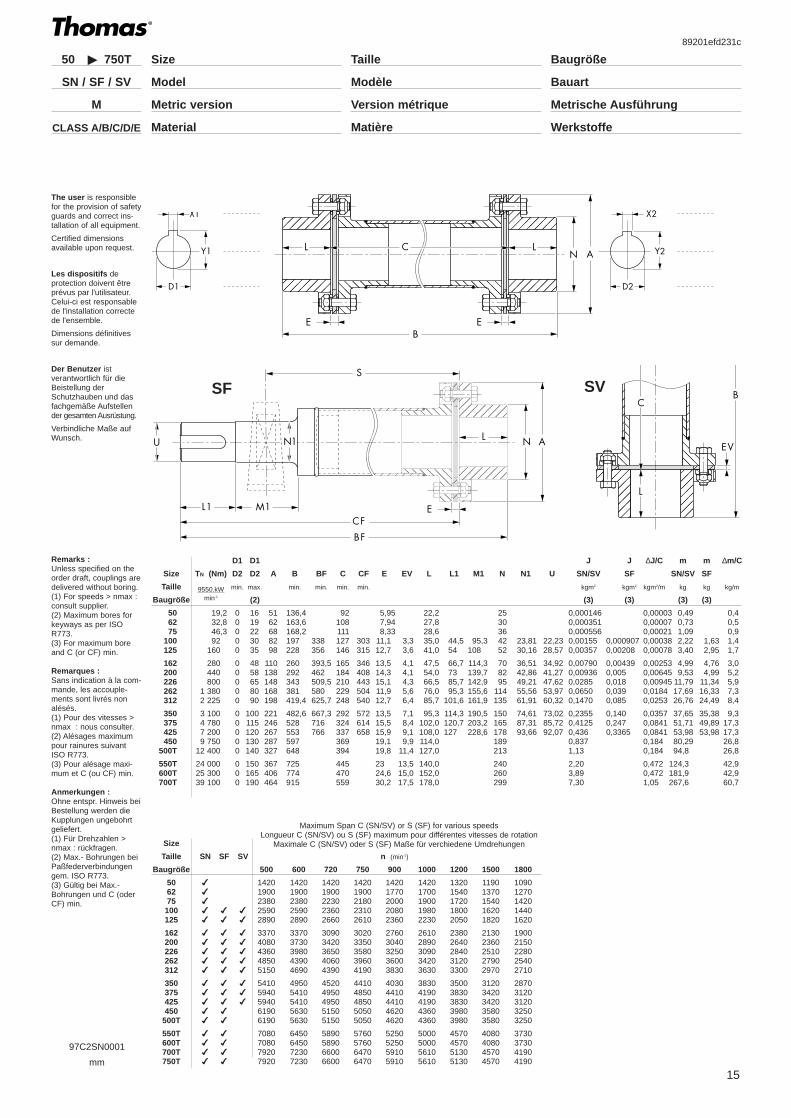
Size TN (Nm) D2 D2 A B BF C CF E EV L L1 M1 N N1 U
Taille 9550.kW min. max. min. min. min. min.
Baugröße min-1 (2)
50 19,2 0 16 51 136,4 92 5,95 22,2 2562 32,8 0 19 62 163,6 108 7,94 27,8 3075 46,3 0 22 68 168,2 111 8,33 28,6 36
100 92 0 30 82 197 338 127 303 11,1 3,3 35,0 44,5 95,3 42 23,81 22,23125 160 0 35 98 228 356 146 315 12,7 3,6 41,0 54 108 52 30,16 28,57
162 280 0 48 110 260 393,5 165 346 13,5 4,1 47,5 66,7 114,3 70 36,51 34,92200 440 0 58 138 292 462 184 408 14,3 4,1 54,0 73 139,7 82 42,86 41,27226 800 0 65 148 343 509,5 210 443 15,1 4,3 66,5 85,7 142,9 95 49,21 47,62262 1 380 0 80 168 381 580 229 504 11,9 5,6 76,0 95,3 155,6 114 55,56 53,97312 2 225 0 90 198 419,4 625,7 248 540 12,7 6,4 85,7 101,6 161,9 135 61,91 60,32
350 3 100 0 100 221 482,6 667,3 292 572 13,5 7,1 95,3 114,3 190,5 150 74,61 73,02375 4 780 0 115 246 528 716 324 614 15,5 8,4 102,0 120,7 203,2 165 87,31 85,72425 7 200 0 120 267 553 766 337 658 15,9 9,1 108,0 127 228,6 178 93,66 92,07450 9 750 0 130 287 597 369 19,1 9,9 114,0 189
500T 12 400 0 140 327 648 394 19,8 11,4 127,0 213
550T 24 000 0 150 367 725 445 23 13,5 140,0 240600T 25 300 0 165 406 774 470 24,6 15,0 152,0 260700T 39 100 0 190 464 915 559 30,2 17,5 178,0 299
Size
Taille SN SF SV n (min-1)
Baugröße 500 600 720 750 900 1000 1200 1500 1800
50 � 1420 1420 1420 1420 1420 1420 1320 1190 109062 � 1900 1900 1900 1900 1770 1700 1540 1370 127075 � 2380 2380 2230 2180 2000 1900 1720 1540 1420100 � � � 2590 2590 2360 2310 2080 1980 1800 1620 1440125 � � � 2890 2890 2660 2610 2360 2230 2050 1820 1620
162 � � � 3370 3370 3090 3020 2760 2610 2380 2130 1900200 � � � 4080 3730 3420 3350 3040 2890 2640 2360 2150226 � � � 4360 3980 3650 3580 3250 3090 2840 2510 2280262 � � � 4850 4390 4060 3960 3600 3420 3120 2790 2540312 � � � 5150 4690 4390 4190 3830 3630 3300 2970 2710
350 � � � 5410 4950 4520 4410 4030 3830 3500 3120 2870375 � � � 5940 5410 4950 4850 4410 4190 3830 3420 3120425 � � � 5940 5410 4950 4850 4410 4190 3830 3420 3120450 � � 6190 5630 5150 5050 4620 4360 3980 3580 3250
500T � � 6190 5630 5150 5050 4620 4360 3980 3580 3250
550T � � 7080 6450 5890 5760 5250 5000 4570 4080 3730600T � � 7080 6450 5890 5760 5250 5000 4570 4080 3730700T � � 7920 7230 6600 6470 5910 5610 5130 4570 4190750T � � 7920 7230 6600 6470 5910 5610 5130 4570 4190
J J ∆J/C m m ∆m/C
SN/SV SF SN/SV SF
kgm2 kgm2 kgm2/m kg kg kg/m
(3) (3) (3) (3)
0,000146 0,00003 0,49 0,40,000351 0,00007 0,73 0,50,000556 0,00021 1,09 0,90,00155 0,000907 0,00038 2,22 1,63 1,40,00357 0,00208 0,00078 3,40 2,95 1,7
0,00790 0,00439 0,00253 4,99 4,76 3,00,00936 0,005 0,00645 9,53 4,99 5,20,0285 0,018 0,00945 11,79 11,34 5,90,0650 0,039 0,0184 17,69 16,33 7,30,1470 0,085 0,0253 26,76 24,49 8,4
0,2355 0,140 0,0357 37,65 35,38 9,30,4125 0,247 0,0841 51,71 49,89 17,30,436 0,3365 0,0841 53,98 53,98 17,30,837 0,184 80,29 26,81,13 0,184 94,8 26,8
2,20 0,472 124,3 42,93,89 0,472 181,9 42,97,30 1,05 267,6 60,7
Remarks :Unless specified on theorder draft, couplings aredelivered without boring.(1) For speeds > nmax :consult supplier.(2) Maximum bores forkeyways as per ISOR773.(3) For maximum boreand C (or CF) min.
Remarques :Sans indication à la com-mande, les accouple-ments sont livrés nonalésés.(1) Pour des vitesses >nmax : nous consulter.(2) Alésages maximumpour rainures suivantISO R773.(3) Pour alésage maxi-mum et C (ou CF) min.
Anmerkungen :Ohne entspr. Hinweis beiBestellung werden dieKupplungen ungebohrtgeliefert.(1) Für Drehzahlen >nmax : rückfragen.(2) Max.- Bohrungen beiPaßfederverbindungengem. ISO R773.(3) Gültig bei Max.-Bohrungen und C (oderCF) min.
Baugröße
Bauart
Taille
Modèle
Size
Model
50 750T
SN / SF / SV
89201efd231c
15
��
���
�
yy
yyy
y
�
���
����
����
��
y
yyy
yyyy
yyyy
yy
��
����
�����
����
yy
yyyy
yyyyy
yyyy
�� yy�� yy��� yyy
��yy
��
���
�
yy
yyy
y
��
����
�����
���
yy
yyyy
yyyyy
yyy
���
����
����
��
yyy
yyyy
yyyy
yy
��� yyy��yy
��yy�� yy
��
���
���
�� y
y
yyy
yyy
yy �
�
���
�� y
y
yyy
yy
��
��yy
yy �
�
����
�����
���
yy
yyyy
yyyyy
yyy
����
�����
����
��
yyyy
yyyyy
yyyy
yy
��yy
�� yy
����
yyyy
��yy
������
yyyyyy
������
yyyyyy
�
��y
yy
�
���
����
����
��
y
yyy
yyyy
yyyy
yy
��
����
�����
����
yy
yyyy
yyyyy
yyyy
��yy�� yy�� yy�� yy
�
�
�
�
������
yyyyyy �
�
���
���
���
���
���
���
��
��
���
���
���
��
���
�����
�������
���������
�����������
������������
������������
����������
��������
������
����
���
�����
������
��������
����������
����������
����������
���������
�������
�����
����
����
���
��
����
����
���������������
��
���
���
���
��
��
����
������
��������
����������
�����������
�����������
����������
��������
������
����
��
��
����
������
��������
����������
�����������
�����������
����������
��������
������
����
��
����
���
��
����
����
����� y
yyyy �
�� yyy����
����
����
yyyy
yyyy
yyyy
����
yyyy�
��
�����
����
��
yyy
yyyyy
yyyy
yy
��
����
�����
���
�
yy
yyyy
yyyyy
yyy
y
����
�����
����
��
yyyy
yyyyy
yyyy
yy
�� yy��� yyy
��
���
��
yy
yyy
yy
��
��
��
�
yy
yy
yy
y
�y�� yy
SVSF
Maximum Span C (SN/SV) or S (SF) for various speedsLongueur C (SN/SV) ou S (SF) maximum pour différentes vitesses de rotation
Maximale C (SN/SV) oder S (SF) Maße für verchiedene Umdrehungen
Metrische AusführungVersion métriqueMetric versionM
WerkstoffeMatièreMaterialCLASS A/B/C/D/E
DescriptionAMR-MCMR-M Description Beschreibung
89201efd231c
The AMR is a heavy duty, slow tomedium speed coupling used whenhigh starting torque or shock loads,torque reversal, or continuous alter-nating torque exist.
The open lug center member isdesigned to provide ample workspace during installation while mini-mizing the couplings overall length.
Use of the CMR adapter plate inthe place of one of the AMR hubspermits the coupling to directly boltonto an engine or compressor flyw-heel.
L’AMR est un accouplement pourservice intensif, à faible voiremoyenne vitesse. Il est utilisé encas de forts couples de démarrageou de chocs, inversion de coupleou lors de couple alternant encontinu.
L’élément central à tenons estconçu de façon à laisser un espacede travail suffisant lors de l’installa-tion tout en conservant une lon-gueur hors tout minimum.
L’utilisation du plateau d’adaptationdu CMR à la place de l’un desmoyeux de l’AMR, permet à l’ac-couplement d’être fixé directementsur le volant d’inertie d’un moteurthermique ou d’un compresseur.
Die AMR ist eine Hochleistungs-kupplung für kleine bis mittlereDrehzahlen. Sie wird für starkeAnlaufdrehmomente oder stoß-weises Anlaufen, für Drehmoment-umkehr oder ständig wechselndeDrehmomente verwendet.
Das Mittelelement mit offenerAuflage ist so ausgelegt, daß währendder Installation reichlichArbeitsraum zur Verfügung steht,während die gesamte Kupplungs-länge auf ein Mindestmaß begrenztbleibt.
Die Verwendung eines Flanschesan Stelle einer der AMR-Nabenermöglicht es, die Kupplung direktan das Schwungrad z.B. einesMotors oder Kompressors zuschrauben.
Materials Matières Werkstoffe
Hubs
Cast iron.
Center member
Sizes 162-600 : cast iron.
Sizes 700 and up : cast steel.
Disc packs
Tomaloy or stainless steel.Stainless steel in recommended forcorrosive applications.
Hardware
Alloy steel, may be furnished pla-ted.
Moyeux
Fonte.
Elément central
Tailles 162 à 600 : fonte.
Tailles 700 et au dessus : Aciermoulé.
Paquets de disques
Tomaloy ou acier inoxydable.L’acier inoxydable est recommandépour les applications corrosives.
Visserie
Acier allié, peut être fournie traitéeen surface.
Naben
Gußlegierung
Mittelelement
Größe 162-600: Guß
Größe 700 und höher: Stahlguß
Lamellenpakete
Tomaloy- oder rostfreier Stahl
Rostfreier Stahl wird empfohlen beiAnwendungen in korrosivemUmfeld.
Kleinteile
Stahllegierung, auf Anfrage beschichtetlieferbar
16
Typical applications Applications typiques Typische Anwendungen
Reciprocating pumps and compres-sors, fans, blowers, crushers,extruders, hoists, dredges, genera-tors, chippers, calenders, milldrives, conveyors.
Pompes et compresseurs à pis-tons, ventilateurs, souffleurs,concasseurs, extrudeuses,levages, dragueuses, génératrices,broyeurs, calandres, convoyeurs.
Hubkolbenpumpen und -kompres-soren, Ventilatoren, Gebläse,Brecher, Extrusionsmaschinen,Fördermaschinen, Bagger,Generatoren, Mühlen, Kalander,Förderanlagen.

97C2CMR001
mm
The user is responsiblefor the provision of safetyguards and correct ins-tallation of all equipment.
Certified dimensionsavailable upon request.
Les dispositifs deprotection doivent êtreprévus par l'utilisateur.Celui-ci est responsablede l'installation correctede l'ensemble.
Dimensions définitivessur demande.
Der Benutzer istverantwortlich für dieBeistellung derSchutzhauben und dasfachgemäße Aufstellender gesamten Ausrüstung.
Verbindliche Maße aufWunsch.
89201efd231c
17
����
����
����
����
����
yyyy
yyyy
yyyy
yyyy
yyyy
�����������
yyyyyyyyyyy
���
�����
�����
����
��
yyy
yyyyy
yyyyy
yyyy
yy
���yyy
��� yyy
��
����
������
�����
����
yy
yyyy
yyyyyy
yyyyy
yyyy
�����������
yyyyyyyyyyy
����
yyyy�� yy
���
�����
������
����
��
yyy
yyyyy
yyyyyy
yyyy
yy
�����������
yyyyyyyyyyy
�y��� yyy
��
����
�����
�����
���
�
yy
yyyy
yyyyy
yyyyy
yyy
y
���
�����
������
�����
����
yyy
yyyyy
yyyyyy
yyyyy
yyyy
�����������
yyyyyyyyyyy
����
yyyy��� yyy
D1 D1 J J m m
Size TN (Nm) nmax D2 D2 A BA BC CA CC L N Q T AMR CMR AMR CMR
Taille 9550.kW min-1 min. max. min. kgm2 kgm2 kg kg
Baugröße min-1 (1) (2) inch (3) (3) (3) (3)
162 490 2 500 0 42 117 156 129 66,7 84,1 44 70 61/4 7,9 0,0059 0,0079 4,0 3,6200 960 2 500 0 50 146 184 152 76,2 98,4 54 92 73/8 9,5 0,016 0,0199 6,4 5,4225 1 360 2 500 0 58 152 203 162 76,2 98,4 64 98 75/8 9,5 0,021 0,038 8,5 7,3262 1 730 2 500 0 65 175 235 186 88,9 113,7 73 114 87/8 11,1 0,043 0,0553 12,5 11,8312 2 430 2 500 0 80 206 276 221 104,8 134,9 86 138 10 12,7 0,108 0,1144 22,0 18,1
350 5 430 2 300 0 90 232 306 244 115,9 149,2 95 152 107/8 12,7 0,183 0,1843 30,5 25,4375 7 100 2 200 0 95 256 333 270 130,2 168,3 102 165 117/8 14,3 0,299 0,3043 41,5 34,9425 9 040 1 900 0 110 280 357 289 141,3 181,0 108 178 131/8 15,9 0,468 0,5208 53,5 45,8450 11 190 1 500 0 115 302 379 308 150,8 193,7 114 189 143/4 17,5 0,626 0,7227 64,4 57,2500 16 500 1 500 0 130 341 427 349 173,0 222,2 127 213 161/2 19,1 1,24 1,393 91,6 81,6
550 21 360 1 500 0 140 381 475 391 195,3 250,8 140 240 18 22,2 2,02 2,253 126 111600 29 500 1 200 0 150 425 519 429 214,3 276,3 152 262 191/2 25,4 3,22 3,599 170 150700 46 900 1 100 0 175 481 600 494 244,5 315,9 178 298 221/2 25,4 6,29 6,818 260 227750 60 200 1 000 0 190 524 635 527 266,7 342,9 184 321 24 28,6 9,45 1,036 310 277800 77 400 900 0 200 568 683 572 288,9 374,7 197 349 255/8 31,8 17,15 17,176 405 363
850 92 300 850 0 215 603 727 610 308,0 400,0 210 368 273/8
31,8 20,25 21,448 500 442925 117 500 800 0 235 654 794 667 336,6 438,2 229 403 287/8 34,9 31,0 31,31 630 5351000 147 000 750 0 250 718 851 713 368,3 471,5 241 445 315/8 41,3 48,0 45,353 900 7481100 175 000 700 0 280 768 914 764 393,7 503,2 260 470 333/8 44,5 74,0 72,273 1030 8851200 205 600 650 0 305 848 992 827 433,4 547,7 279 514 371/2 50,8 119,4 119,09 1300 1157
1300 245 200 600 0 330 914 1075 897 465,1 592,1 305 572 397/8 54 164 165,905 1770 15061550 320 900 600 0 390 997 1230 972 493,7 603,3 368 660 435/8 54 260 245,785 2340 1860
Remarks :Unless specified on theorder draft, couplings aredelivered without boring.(1) For speeds > nmax :consult supplier.(2) Maximum bores forkeyways as per ISOR773.(3) For maximum boreand minimum adapterdiameter.(4) S.A.E. is used forlight duty. For heavy dutyuse Thomas bolting.
Remarques :Sans indication à la com-mande, les accouple-ments sont livrés nonalésés.(1) Pour des vitesses >nmax : nous consulter.(2) Alésages maximumpour rainures suivantISO R773.(3) Pour alésage maxi-mum et taille de brideminimum.(4) S.A.E. est utilisé pourservice léger. Pour servi-ce lourd préférer la fixa-tion Thomas.
Anmerkungen :Ohne entspr. Hinweis beiBestellung werden dieKupplungen ungebohrtgeliefert.(1) Für Drehzahlen >nmax : rückfragen.(2) Max.- Bohrungen beiPaßfederverbindungengem. ISO R773.(3) Gültig bei Max.-Bohrungen und Min.Flansch Durchmesser.(4) S.A.E. bei leichtenmBetrieb. Bei schweremBetrieb ThomasVerschraubungen ver-wenden.
Baugröße
Bauart
Taille
Modèle
Size
Model
162 1550
AMR / CMR
�
�
�
�
Q Size - Taille - Baugrößestd 162 200 225 262 312 350 375 425 450 500 550 600 700 750 800 850 925 � 1550
inch
81/2 � � � �91/2 � � � � �
103/8 � � � � �123/8 � � � � � � �137/8 � � � � � � �
16 � � � � � � �183/8 � � � � � � � � �203/8 � � � � � � � � �221/2 � � � � � � � � �261/2 � � � � � � �
287/8 � � � � � � �
U V U VS.A.E. (4) Thomas (4)
inch inch
6 x 8,7 77/8 8 x 10,3 71/2
8 x 8,7 83/4 8 x 11,9 85/8
6 x 10,3 95/8 8 x 11,9 91/2
8 x 10,3 115/8 8 x 13,5 111/2
8 x 10,3 131/8 8 x 16,7 121/2
- - 8 x 19,8 143/8
8 x 13,5 171/4 8 x 19,8 163/4
8 x 13,5 191/4 8 x 23,0 181/2
6 x 16,7 213/8 8 x 26,2 201/2
12 x 16,7 251/4 12 x 26,2 241/2
12 x 19,8 271/4 12 x 26,2 267/8
Con
sult
supp
lier
Nou
s co
nsul
ter
Rüc
kfra
gen
Metrische AusführungVersion métriqueMetric versionM

AustriaBrook Hansen Austria
ViennaTel 1 774 5759Fax 1 774 5758
Rexnord Kette GmbG & Co. KGTraiskirchenTel 2 252 54769Fax 2 252 57177
BelgiumBrook Hansen Belgium
VilvoordeTel 02 255 42 11Fax 02 252 52 82
Rexnord Belgium NV/SAZaventemTel 02 725 4060Fax 02 720 1023
DenmarkBrook Hansen AB
CharlottenlundTel 3963 6270Fax 2046 1841
Rexnord PTCopenhagenTel 4814 6911Fax 4814 6912
FranceBrook Hansen Sales France
LyonTel 04 72 60 02 40Fax 04 78 95 15 44ParisTel 01 47 60 19 60Fax 01 47 81 29 29Baccarat (Nancy)Tel 03 83 75 57 16Fax 03 83 75 57 20
GermanyRexnord Stephan GmbH & Co.KG
GevelslergTel 0 2332 66 360Fax 0 2332 66 3630
Rexnord AntriebstechnikDortmundTel 0 2318 294 0Fax 0 2318 272 74
Rexnord Kette GmbH & Co. KGBetzdorfTel 0 2741 284 0Fax 0 2741 284 385
ItalyRexnord Italia
MilanoTel 02 2699 271Fax 02 2699 2750
The NetherlandsBrook Hansen BV
AlmeloTel 546 488 500Fax 546 872 035
NorwayBrook Hansen AS
LanghusTel 64 86 08 00Fax 64 86 76 70
SwedenBrook Hansen AB
SpångaTel 08 445 71 20Fax 08 445 71 30
SwitzerlandBrook Hansen Schweiz
BeromünsterTel 41 93 00611Fax 41 93 00612
United KingdomRexnord Hansen
HuddersfieldTel 01484 431 414Fax 01484 431 426
Rexnord BelgiumCumbriaTel 015394 42252Fax 015394 48653
CanadaBrook Hansen Canada Inc.
MontréalTel 514 735 1521Fax 514 342 2877VancouverTel 604 533 1580Fax 604 533 0759TorontoTel 416 675 3844Fax 416 675 6885
Rexnord Canada Ltd.EdmontonTel 403 463 9444Fax 403 450 4973MontréalTel 514 631 4444Fax 514 631 9163TorontoTel 416 297 6868Fax 416 297 6873VancouverTel 604 435 5000Fax 604 435 6516
United States of AmericaRexnord Corporation
AtlantaTel 404 431 7300Fax 404 431 7298ColombusTel 614 276 7235Fax 614 276 1137DallasTel 817 640 9393Fax 817 640 8704Kansas CityTel 816 361 8889Fax 816 523 5403Los AngelesTel 818 552 6100Fax 818 552 6108MilwaukeeTel 414 797 8348Fax 414 797 8761PhiladelphiaTel 215 638 9696Fax 215 638 9350RoanokeTel 703 772 0451Fax 703 772 3328SeattleTel 206 251 0787Fax 206 251 0795
BrazilRexnord Correntes Ltda.
São PaoloTel 011 6221 2283Fax 011 6221 6745São LeopoldoTel 051 588 3000Fax 051 588 1334
MexicoRexnord SA
QueretaroTel 42 18 50 00Fax 42 18 10 90
(Miami - Florida - U.S.A.)Rexnord International Inc.Tel 305 592 4367Fax 305 592 5384
JapanBTR Japan Ltd
TokyoTel 3 5224 3302Fax 3 5224 3300
SingaporeBrook Hansen
SingaporeTel 332 0534Fax 337 8786
Rexnord International Inc.SingaporeTel 338 5622Fax 338 5422
AustraliaBrook Hansen A’Asia Pty Ltd
AdelaideTel 08 83 62 03 99Fax 08 83 62 04 99BrisbaneTel 07 32 79 13 99Fax 07 32 79 13 66MelbourneTel 03 97 29 33 00Fax 03 97 29 76 26NewcastleTel 02 49 52 81 31Fax 02 49 56 19 35PerthTel 08 94 51 87 77Fax 08 94 51 43 89SydneyTel 02 97 92 23 55Fax 02 97 92 26 63
New ZealandBrook Hansen New Zealand Ltd
AucklandTel 92 74 53 53Fax 92 74 52 92ChristchurchTel 03 35 95 971Fax 03 35 93 354
Europe
Canada & United States of America
Asia
South AfricaBrook Hansen
Boksburg (Johannesburg)Tel 11 397 2495Fax 11 397 2585
TunisiaRexnord Hansen Tunisie
TunisiaTel 1 585 261Fax 1 585 261
Africa
Australia & New
Latin America
BrazilFranceGermany
JapanUSA
89201efd231c Every care has been taken to ensure the accuracy of the information contained in this publication, but, due to a policy of continuous developmentand improvement the right is reserved to supply products which may differ slightly from those illustrated and described in this publication.
An Invensys company
L’O
rmon
t Im
prim
eur
ST-
DIE
- 4
000
Ex.
05/
2001