displacement measurement 2
TRANSCRIPT

8/6/2019 Displacement Measurement 2
http://slidepdf.com/reader/full/displacement-measurement-2 1/73
BY- Anil Pathak, Manoj Kumar,Mayank Tripathi,ME( Ist Year), I & C Dept.,
NITTTR ,Chandigarh

8/6/2019 Displacement Measurement 2
http://slidepdf.com/reader/full/displacement-measurement-2 2/73
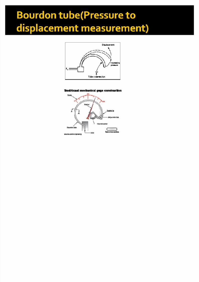
� In an industry it is not possible to measure the
unknown parameters like pressure,
temperature, force, etc directly.
� So we first convert these unknown parameter
in to the displacement and then convert it into electrical form.
8/6/2019 Displacement Measurement 2
http://slidepdf.com/reader/full/displacement-measurement-2 3/73
8/6/2019 Displacement Measurement 2
http://slidepdf.com/reader/full/displacement-measurement-2 4/73
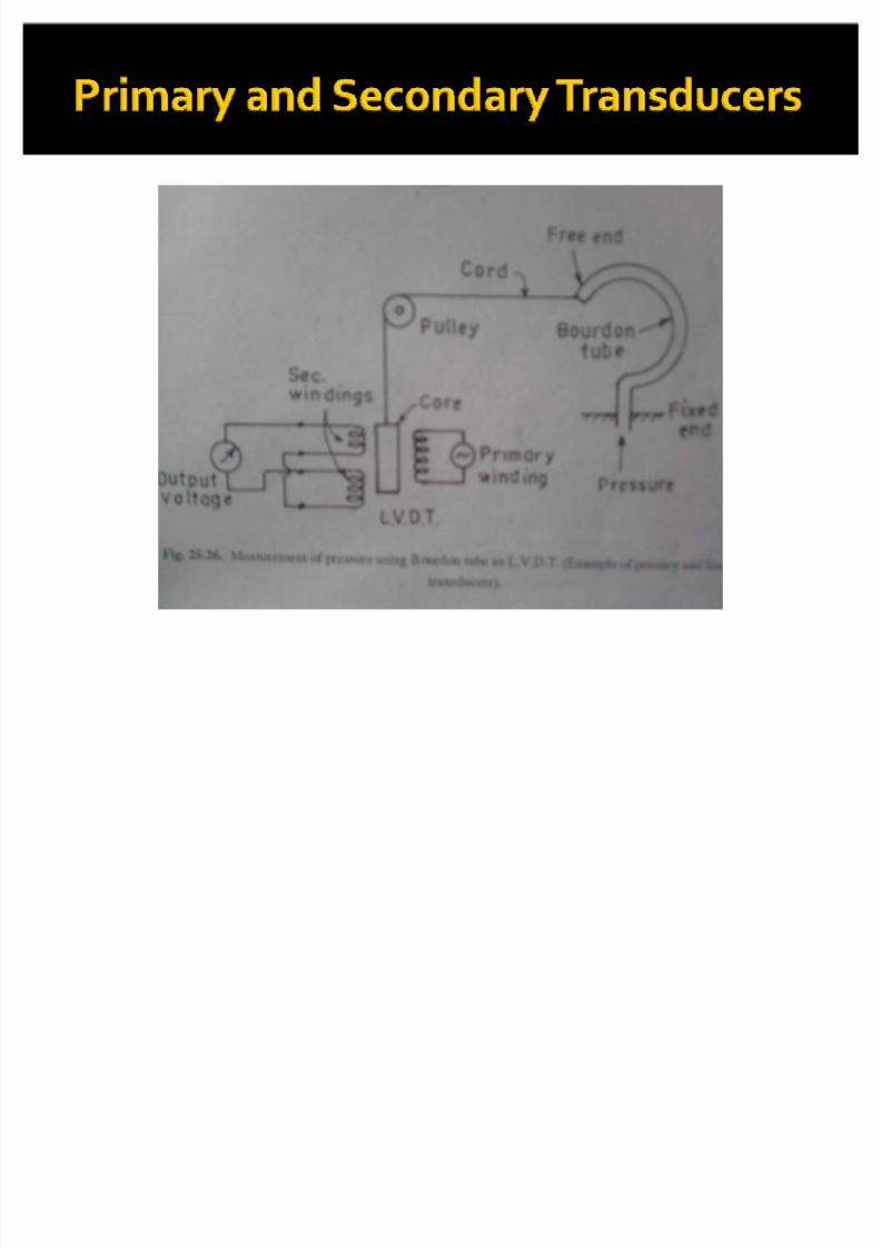
� Now the displacement is can be converted in
to electrical in nature with the help of Linear
variable differential transformer(LVDT),which works as a secondary transducers
�
Where as the bourdon tube is working as aprimary transducers(because it is convertingfirst the pressure in to displacement)
8/6/2019 Displacement Measurement 2
http://slidepdf.com/reader/full/displacement-measurement-2 5/73
8/6/2019 Displacement Measurement 2
http://slidepdf.com/reader/full/displacement-measurement-2 6/73
� The displacement can be dived into two
parts.
� a) Relative Displacement
� b) Absolute Displacement
8/6/2019 Displacement Measurement 2
http://slidepdf.com/reader/full/displacement-measurement-2 7/73
� The relative displacement is measured with
respect to a fixed reference.
� In such device one terminal of the instrument
is attached to a point fixed in space and theother terminal is attached( mechanically or
electrically) to the point whose motion is tobe measured.
8/6/2019 Displacement Measurement 2
http://slidepdf.com/reader/full/displacement-measurement-2 8/73

8/6/2019 Displacement Measurement 2
http://slidepdf.com/reader/full/displacement-measurement-2 9/73
8/6/2019 Displacement Measurement 2
http://slidepdf.com/reader/full/displacement-measurement-2 10/73

8/6/2019 Displacement Measurement 2
http://slidepdf.com/reader/full/displacement-measurement-2 11/73
� The devices used for the measurement of
relative displacement are :-
i) Inductive Type
ii) Capacitive typeiii) Piezo-electric Type
iv) Digital Displacement measuring typev) Resistive Typevi) Ultrasonic Type
8/6/2019 Displacement Measurement 2
http://slidepdf.com/reader/full/displacement-measurement-2 12/73
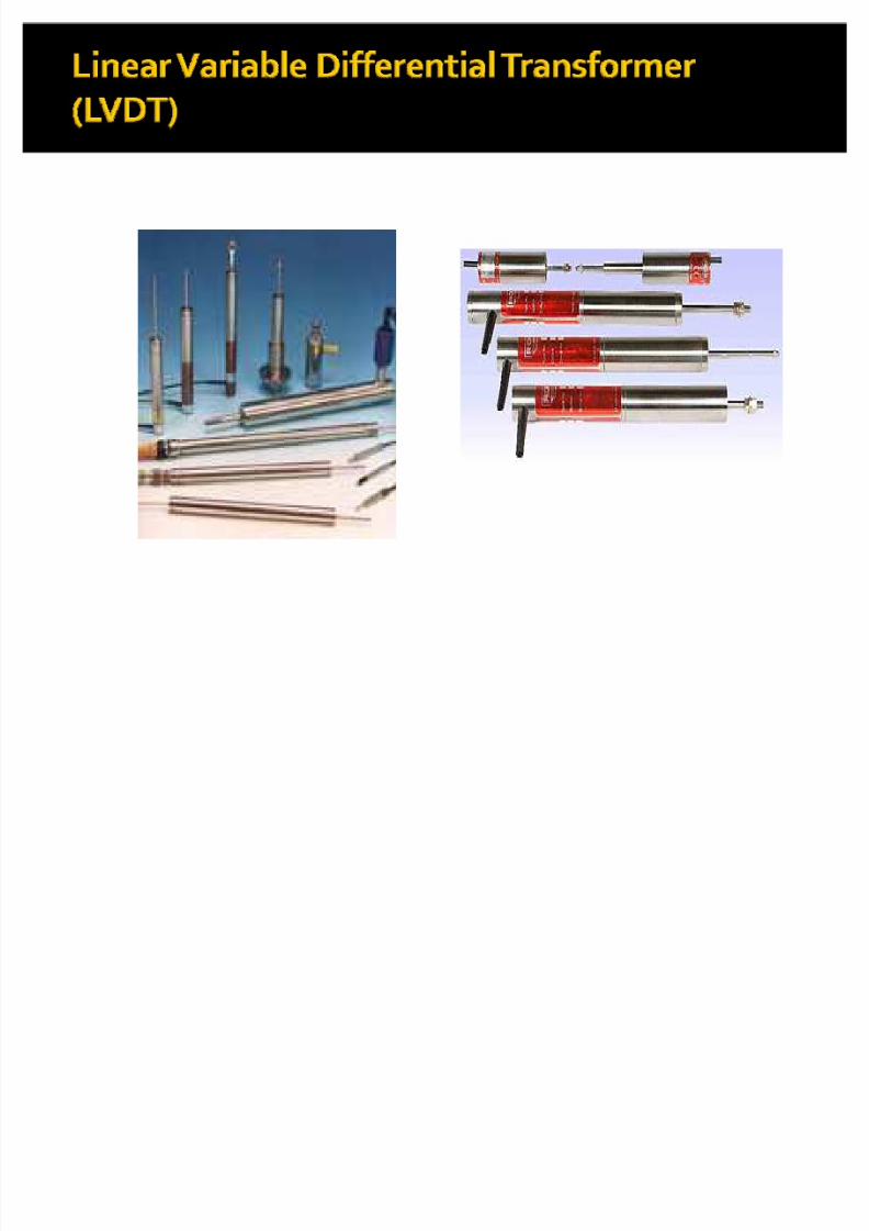
� The most widely used inductive transducers
to translate the linear displacement into
electrical signal are � Linear Variable Differential Transformer
(LVDT)� And for the translation of rotational
displacement into electrical signals are-� Rotary Variable Differential Transformer
(RVDT)
8/6/2019 Displacement Measurement 2
http://slidepdf.com/reader/full/displacement-measurement-2 13/73
8/6/2019 Displacement Measurement 2
http://slidepdf.com/reader/full/displacement-measurement-2 14/73
� The transformer consists of a single primary
winding(P) and two secondary windings S1 and S2wound on a cylindrical former.
� The secondary windings have equal numbers of turns and are identically placed on either side of the
primary windings.� The primary winding is connected to an alternating
current source.� A movable soft iron core is placed inside the former.
8/6/2019 Displacement Measurement 2
http://slidepdf.com/reader/full/displacement-measurement-2 15/73
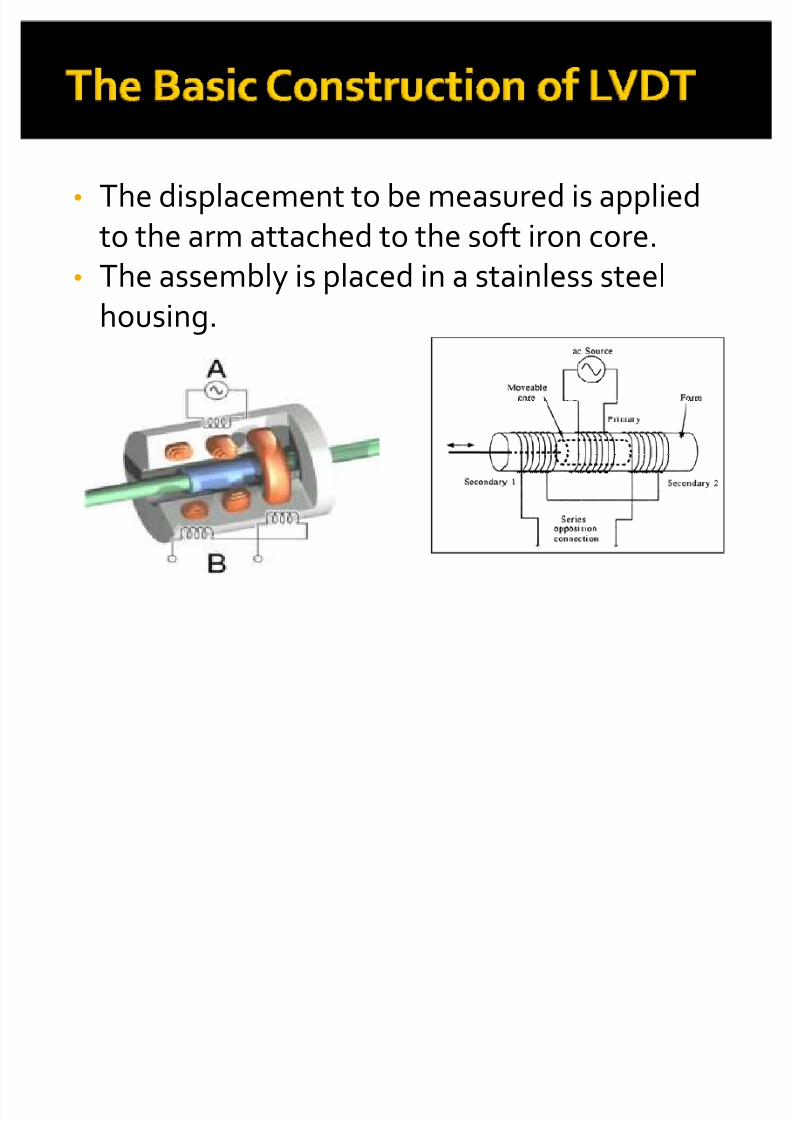
� The displacement to be measured is applied
to the arm attached to the soft iron core.
� The assembly is placed in a stainless steelhousing.
8/6/2019 Displacement Measurement 2
http://slidepdf.com/reader/full/displacement-measurement-2 16/73
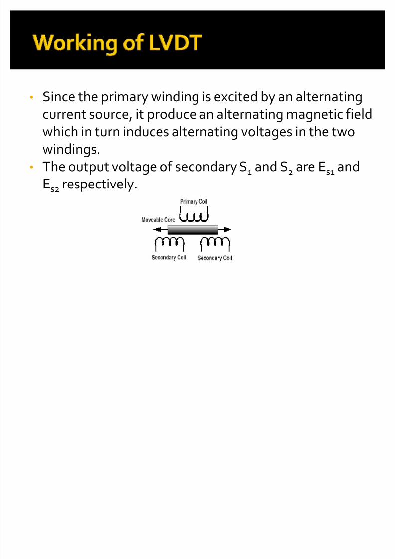
� Since the primary winding is excited by an alternatingcurrent source, it produce an alternating magnetic field
which in turn induces alternating voltages in the twowindings.� The output voltage of secondary S1 and S2 are Es1 and
Es2 respectively.
8/6/2019 Displacement Measurement 2
http://slidepdf.com/reader/full/displacement-measurement-2 17/73
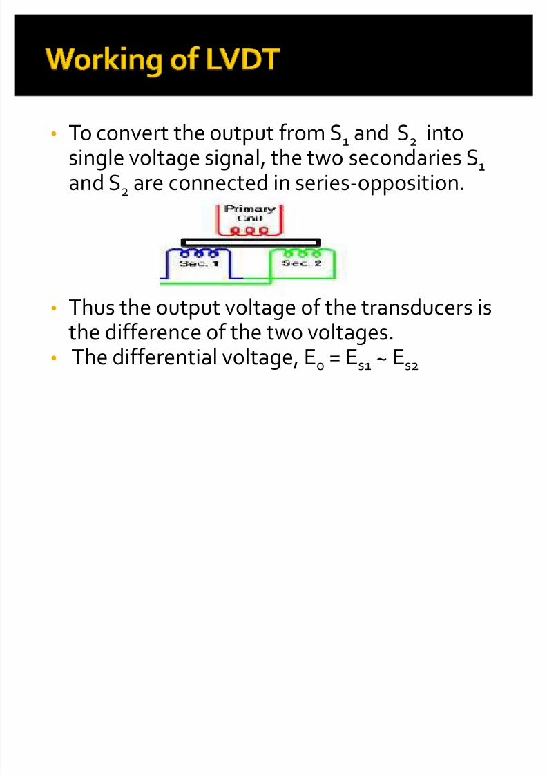
� To convert the output from S1 and S2 intosingle voltage signal, the two secondaries S1
and S2 are connected in series-opposition.
� Thus the output voltage of the transducers isthe difference of the two voltages.
� The differential voltage, E0 = Es1 ~ Es2
8/6/2019 Displacement Measurement 2
http://slidepdf.com/reader/full/displacement-measurement-2 18/73
� At NULL position, the flux linking with bothsecondary windings is equal and hence equal emfsare induced in them.(i.e., E
s1= E
s2)and then the
output differential voltage will be zero, E0 = 0.� Now if the core is moved to the left of the NULL
position ,more flux links with S1 and less with S2 , soemf induced in S1 , Es1 is more then emfs induced in
S2 , Es2 (i.e.,Es1 > Es2). So the output differentialvoltage will be, E0 = Es1 - Es2
� And this voltage is in phase with primary voltage.
8/6/2019 Displacement Measurement 2
http://slidepdf.com/reader/full/displacement-measurement-2 19/73
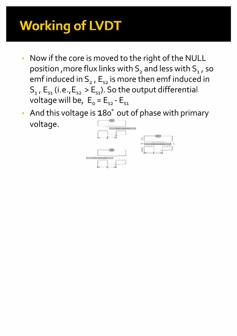
� Now if the core is moved to the right of the NULLposition ,more flux links with S2 and less with S1 , so
emf induced in S2 , Es2 is more then emf induced inS1 , Es1 (i.e.,Es2 > Es1). So the output differentialvoltage will be, E0 = Es2 - Es1
� And this voltage is 180° out of phase with primary
voltage.
8/6/2019 Displacement Measurement 2
http://slidepdf.com/reader/full/displacement-measurement-2 20/73
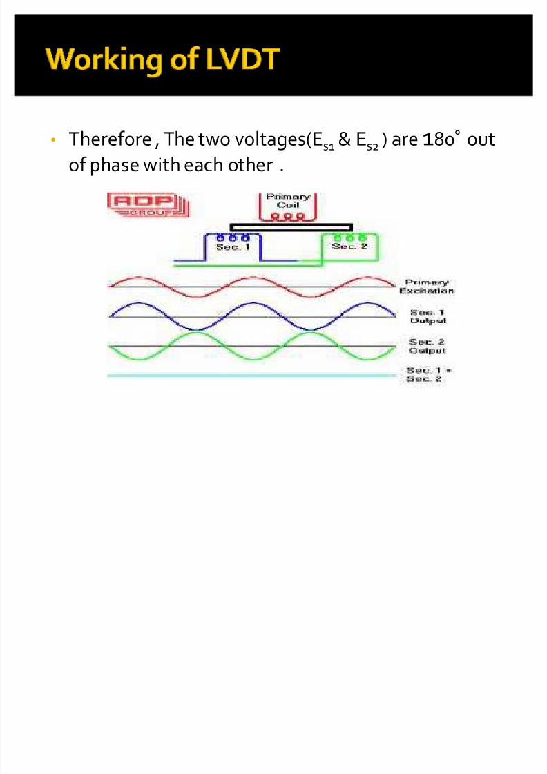
� Therefore , The two voltages(Es1 & Es2 ) are 180° out
of phase with each other .
8/6/2019 Displacement Measurement 2
http://slidepdf.com/reader/full/displacement-measurement-2 21/73
� So the amount of voltage change neither
secondary winding is proportional to the
amount of movement of the core.
� By noting which output voltage is increasingor decreasing ,we can determine the
direction of motion.
8/6/2019 Displacement Measurement 2
http://slidepdf.com/reader/full/displacement-measurement-2 22/73
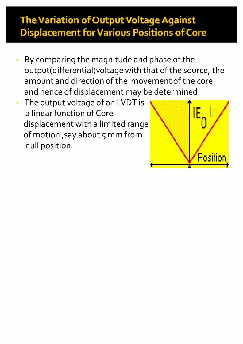
� By comparing the magnitude and phase of theoutput(differential)voltage with that of the source, the
amount and direction of the movement of the coreand hence of displacement may be determined.� The output voltage of an LVDT is
a linear function of Core
displacement with a limited rangeof motion ,say about 5 mm fromnull position.

8/6/2019 Displacement Measurement 2
http://slidepdf.com/reader/full/displacement-measurement-2 23/73

8/6/2019 Displacement Measurement 2
http://slidepdf.com/reader/full/displacement-measurement-2 24/73
� High range:- LVDT can be used used for measurementof displacement of 1.25 mm to 250 mm.
� Frication less:- There is no physical contact betweenthe movable core and the coil structure which meansthe LVDT is a frictionless device
� Low Power Consumption: Most of LVDTs consume
power which is less then 1 watt.
8/6/2019 Displacement Measurement 2
http://slidepdf.com/reader/full/displacement-measurement-2 25/73
� Many a times, the transducer performance is
affected by vibrations.
� Large displacement are required fordifferential output.
� Temperature affects the performance of theLVDT.

8/6/2019 Displacement Measurement 2
http://slidepdf.com/reader/full/displacement-measurement-2 26/73
� LVDT can be use as a secondary transducers so wecan convert pressure, force and weight intodisplacement and then into electrical output.

8/6/2019 Displacement Measurement 2
http://slidepdf.com/reader/full/displacement-measurement-2 27/73

8/6/2019 Displacement Measurement 2
http://slidepdf.com/reader/full/displacement-measurement-2 28/73

8/6/2019 Displacement Measurement 2
http://slidepdf.com/reader/full/displacement-measurement-2 29/73
8/6/2019 Displacement Measurement 2
http://slidepdf.com/reader/full/displacement-measurement-2 30/73
� Clockwise rotation produces an Increasing voltageof a secondary winding of one phase.
� while counterclock-wise rotation produces anincreasing voltage of opposite phase.
8/6/2019 Displacement Measurement 2
http://slidepdf.com/reader/full/displacement-measurement-2 31/73
8/6/2019 Displacement Measurement 2
http://slidepdf.com/reader/full/displacement-measurement-2 32/73
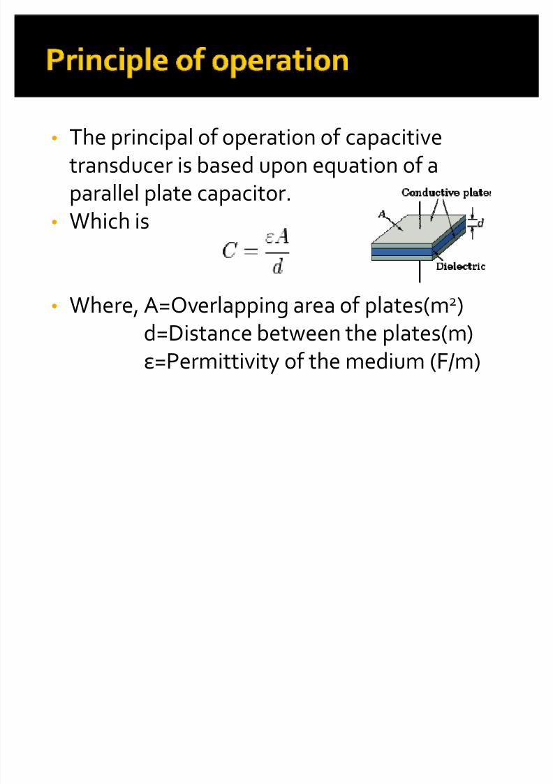
� The principal of operation of capacitive
transducer is based upon equation of a
parallel plate capacitor.� Which is
� Where, A=Overlapping area of plates(m2)d=Distance between the plates(m)
=Permittivity of the medium (F/m)
8/6/2019 Displacement Measurement 2
http://slidepdf.com/reader/full/displacement-measurement-2 33/73
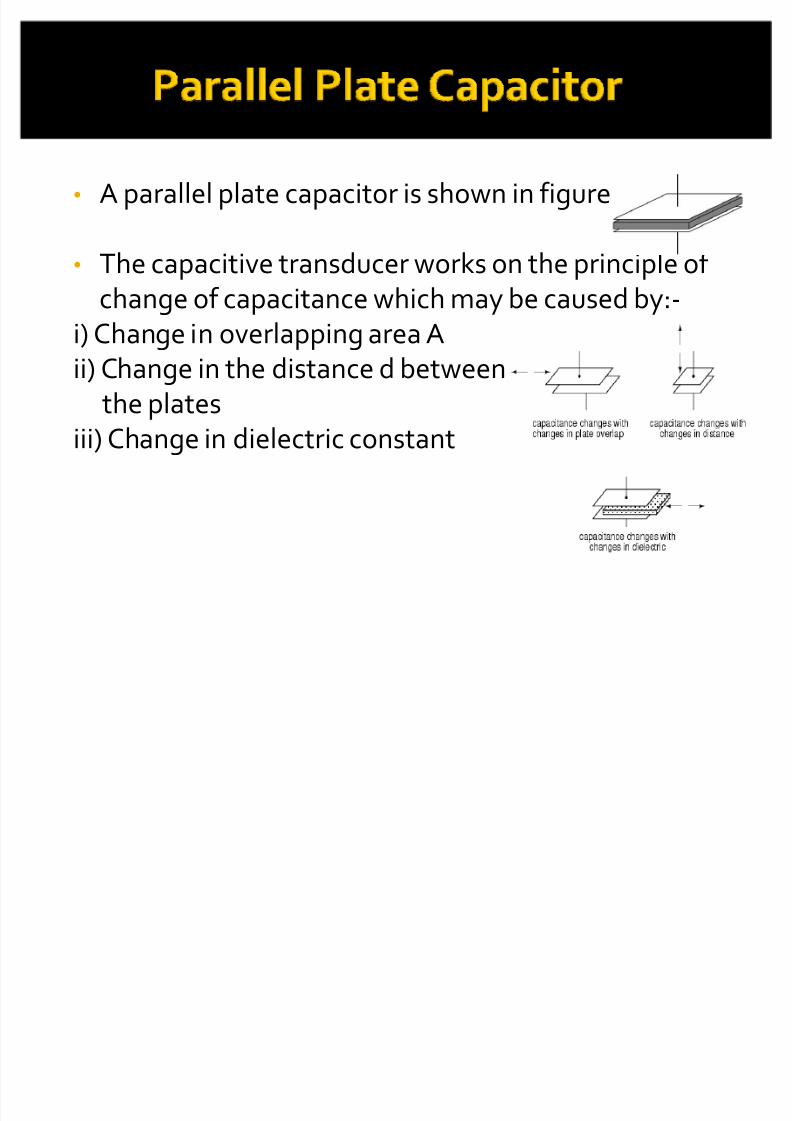
� A parallel plate capacitor is shown in figure-
� The capacitive transducer works on the principle of change of capacitance which may be caused by:-
i) Change in overlapping area Aii) Change in the distance d between
the platesiii) Change in dielectric constant
8/6/2019 Displacement Measurement 2
http://slidepdf.com/reader/full/displacement-measurement-2 34/73
� These changes are caused by physical variable likedisplacement, force and pressure in most of the cases.
� The change in change in dielectric constant as is thecase in measurement of liquid or gas levels.
�
The capacitance may be measured with bridge circuit.
8/6/2019 Displacement Measurement 2
http://slidepdf.com/reader/full/displacement-measurement-2 35/73
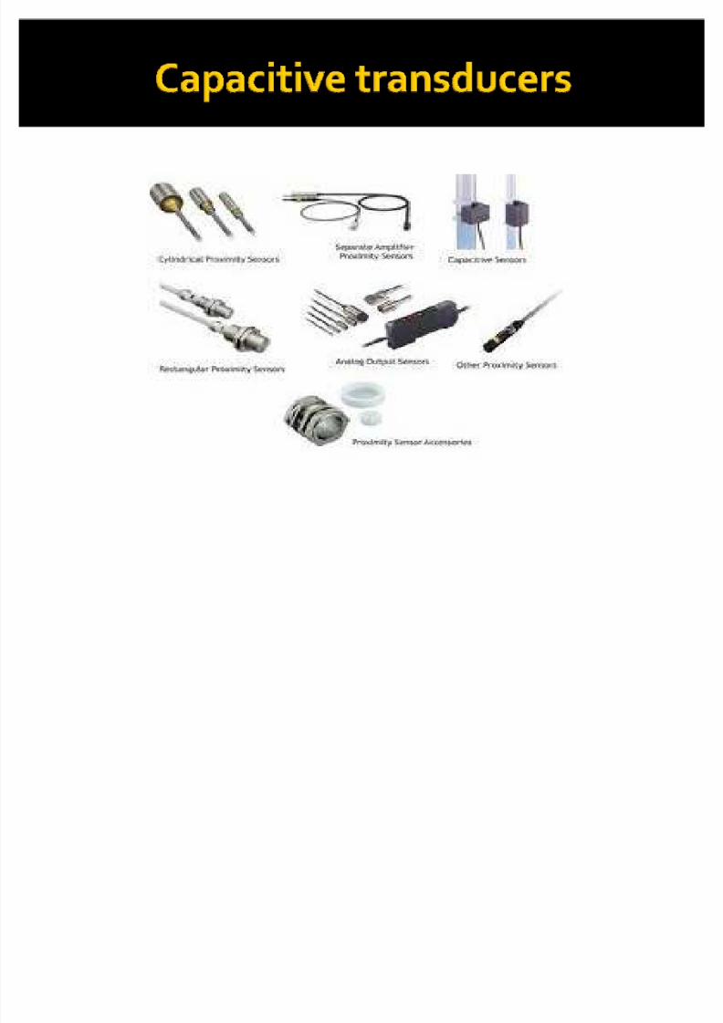
� The capacitive transducer are commonly
used for measurement of linear
displacement.� These transducers use the following effect-
i) Change in capacitance due to change inoverlapping area of plates.
ii) Change in capacitance due to change indistance between the two plates.

8/6/2019 Displacement Measurement 2
http://slidepdf.com/reader/full/displacement-measurement-2 36/73
8/6/2019 Displacement Measurement 2
http://slidepdf.com/reader/full/displacement-measurement-2 37/73
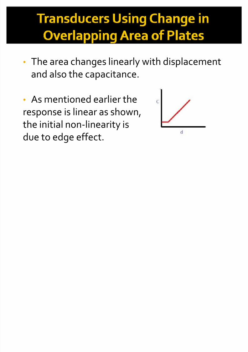
� The area changes linearly with displacement
and also the capacitance.
� As mentioned earlier the
response is linear as shown,the initial non-linearity is
due to edge effect.
8/6/2019 Displacement Measurement 2
http://slidepdf.com/reader/full/displacement-measurement-2 38/73
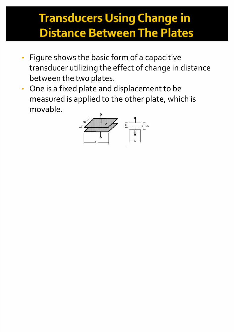
� Figure shows the basic form of a capacitivetransducer utilizing the effect of change in distancebetween the two plates.
� One is a fixed plate and displacement to bemeasured is applied to the other plate, which ismovable.

8/6/2019 Displacement Measurement 2
http://slidepdf.com/reader/full/displacement-measurement-2 39/73
� Since the capacitance , C, varies inversely as thedistance d; between the plates the response of thistransducer is not linear, as shown in the figure-
Thus this transducer is useful only formeasurement of extremely smalldisplacements.
8/6/2019 Displacement Measurement 2
http://slidepdf.com/reader/full/displacement-measurement-2 40/73
� They require extremely small forces to
operate them and hence are very useful for
use in small systems.
� They are extremely sensitive.
� They require small power to operate them.
8/6/2019 Displacement Measurement 2
http://slidepdf.com/reader/full/displacement-measurement-2 41/73
8/6/2019 Displacement Measurement 2
http://slidepdf.com/reader/full/displacement-measurement-2 42/73
� Capacitive transducers are used for the
measurement of both linear and angular
motion.� Capacitive transducers are used for the
measurement of pressure and force, thisforce and pressure is first will converted into
displacement which causes change incapacitance.

8/6/2019 Displacement Measurement 2
http://slidepdf.com/reader/full/displacement-measurement-2 43/73
Piezo-electric Transducers mainly used for measurementof displacement. They can be used for measurement of force, pressure, or acceleration. these quantities when
measured with piezo- electric Transducers are firstconverted in to displacement is subsequently applied tothese Transducers to produce an out put voltage.
8/6/2019 Displacement Measurement 2
http://slidepdf.com/reader/full/displacement-measurement-2 44/73
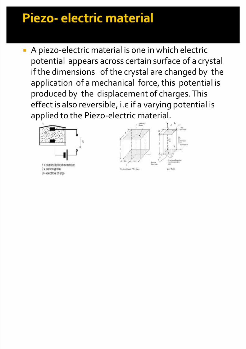
� A piezo-electric material is one in which electricpotential appears across certain surface of a crystalif the dimensions of the crystal are changed by theapplication of a mechanical force, this potential isproduced by the displacement of charges. Thiseffect is also reversible, i.e if a varying potential isapplied to the Piezo-electric material.

8/6/2019 Displacement Measurement 2
http://slidepdf.com/reader/full/displacement-measurement-2 45/73
8/6/2019 Displacement Measurement 2
http://slidepdf.com/reader/full/displacement-measurement-2 46/73
Digital displacementTransducers thatcommunicate ith digital computer and hich have a digital out put. uch transducer have to use ( /D)
converters to realize the digital data.DigitalTransducers are alled ncoders.They are normally in the f orm of linear or otarydisplacement transducers. ther name isDigitizers
Digital encoders linear digitizers.
8/6/2019 Displacement Measurement 2
http://slidepdf.com/reader/full/displacement-measurement-2 47/73
� Classification of Encoders-
� Digital Displacement transducers can be
classified in to 3 categories.� 1- Tachometer transducers
� 2- incremental Transducers
� 3- absolute Transducers
8/6/2019 Displacement Measurement 2
http://slidepdf.com/reader/full/displacement-measurement-2 48/73
8/6/2019 Displacement Measurement 2
http://slidepdf.com/reader/full/displacement-measurement-2 49/73
8/6/2019 Displacement Measurement 2
http://slidepdf.com/reader/full/displacement-measurement-2 50/73
8/6/2019 Displacement Measurement 2
http://slidepdf.com/reader/full/displacement-measurement-2 51/73
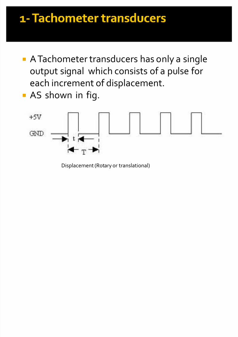
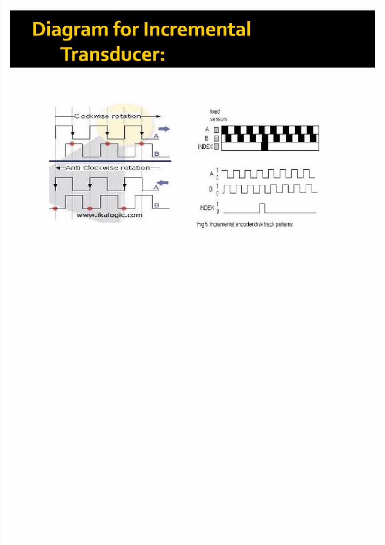
� Two tracks mechanically shifted by ¼ cyclerelative to each other. this is allows detection of motion which signal rises first. Thus up down
pulse counter can be used to subtract pulses .Whenever the motion reverses. Thus a third output , which produces one pulse per revolution ata distinct point. Or zero reference track.
� Advantage that any false pulse resulting fromelectric noise will cause errors. Incrementalencoder used.
8/6/2019 Displacement Measurement 2
http://slidepdf.com/reader/full/displacement-measurement-2 52/73
� Absolute transducers-
� Generally limited to measurement of single
revolution. They use multiple tracks andoutputs, which are read out in parallel to
produce a binary representation of angularshaft input position. Since, there is a one- to-
one correspondence between binaryoutput.

8/6/2019 Displacement Measurement 2
http://slidepdf.com/reader/full/displacement-measurement-2 53/73
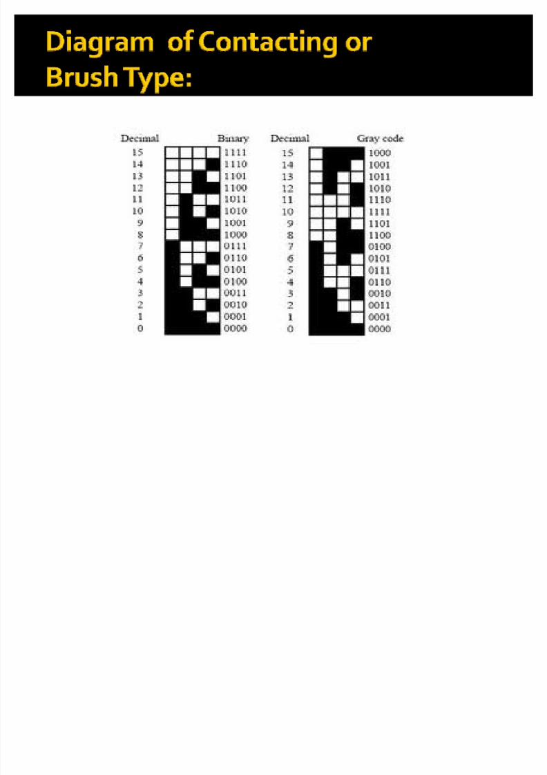
Three type of encoders are given below.
� 1- Tachometer encoders� 2- incremental encoders� 3- absolute encodersThese are Constructed as
(1)Contacting type OR Brush type (Resistiveencoders)
(2) Non Contacting type
The shaded areas are made of conductingmaterial
& unshaded areas are made of non conductingmaterials. As shown in fig.
8/6/2019 Displacement Measurement 2
http://slidepdf.com/reader/full/displacement-measurement-2 54/73
8/6/2019 Displacement Measurement 2
http://slidepdf.com/reader/full/displacement-measurement-2 55/73
1. It is relatively inexpensive.
2. It can be to any degree of desired accuracyprovided that the sector is made largeenough to accommodate the large no. of rows for binary nos. and are quite adequate
for slowly moving system.
8/6/2019 Displacement Measurement 2
http://slidepdf.com/reader/full/displacement-measurement-2 56/73
8/6/2019 Displacement Measurement 2
http://slidepdf.com/reader/full/displacement-measurement-2 57/73
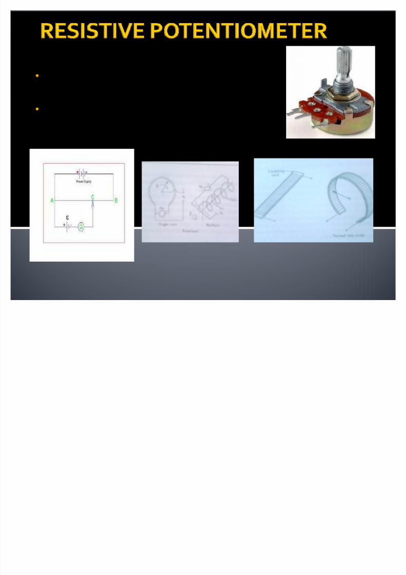
�It consists of a resistance with amovable contact�The motion of contact can betranslational, rotational or helical
8/6/2019 Displacement Measurement 2
http://slidepdf.com/reader/full/displacement-measurement-2 58/73
� SINGLE SLIDE WIRE: Step less variation of resistance as wiper travels over it Length of the wire is limited by the desired stroke in
translational device and by the diameter in rotationaldevice
Limited to small value of resistances Resistance per unit length can be increased by
decreasing the area but then it suffers in the point of view of strength
� WIRE WOUND: Resistive wire is wound on a straight or circular card
depending on the type of device

8/6/2019 Displacement Measurement 2
http://slidepdf.com/reader/full/displacement-measurement-2 59/73
8/6/2019 Displacement Measurement 2
http://slidepdf.com/reader/full/displacement-measurement-2 60/73
8/6/2019 Displacement Measurement 2
http://slidepdf.com/reader/full/displacement-measurement-2 61/73
Power loss: if heat dissipated is limited to P
watts the maximum excitation voltage isgiven by
eex = (P Rp)1/2
for high sensitivity output voltage should be
high for this eex should be high it means for
high sensitivity Rp should also highThis situation contradicts linearity thus the
choice of Rp must be influenced by tradeoff between linearity and sensitivity condition
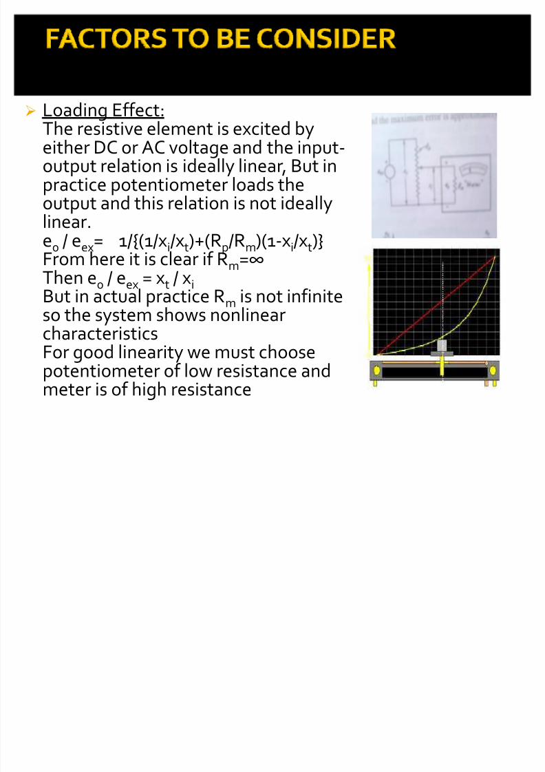
FACTORS TO BE CONSIDER
8/6/2019 Displacement Measurement 2
http://slidepdf.com/reader/full/displacement-measurement-2 62/73

8/6/2019 Displacement Measurement 2
http://slidepdf.com/reader/full/displacement-measurement-2 63/73
ADVANTAGES:1. Inexpensive and simple to use
2. Rather large displacement can be measured3. Sufficient output to drive the control circuitry
DISADVANTAGES:1. Mechanical loading owing to wiper friction2. Electrical noise from wiper contacts3. Quick manipulation generates heat
8/6/2019 Displacement Measurement 2
http://slidepdf.com/reader/full/displacement-measurement-2 64/73

8/6/2019 Displacement Measurement 2
http://slidepdf.com/reader/full/displacement-measurement-2 65/73
8/6/2019 Displacement Measurement 2
http://slidepdf.com/reader/full/displacement-measurement-2 66/73
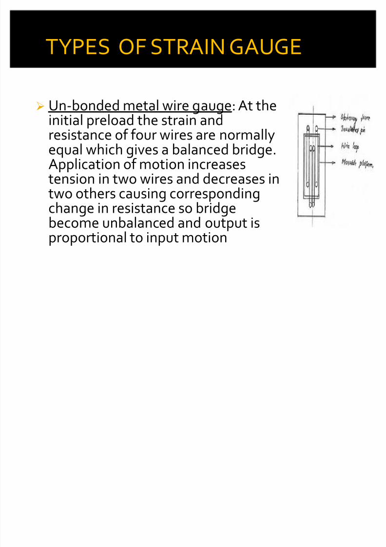
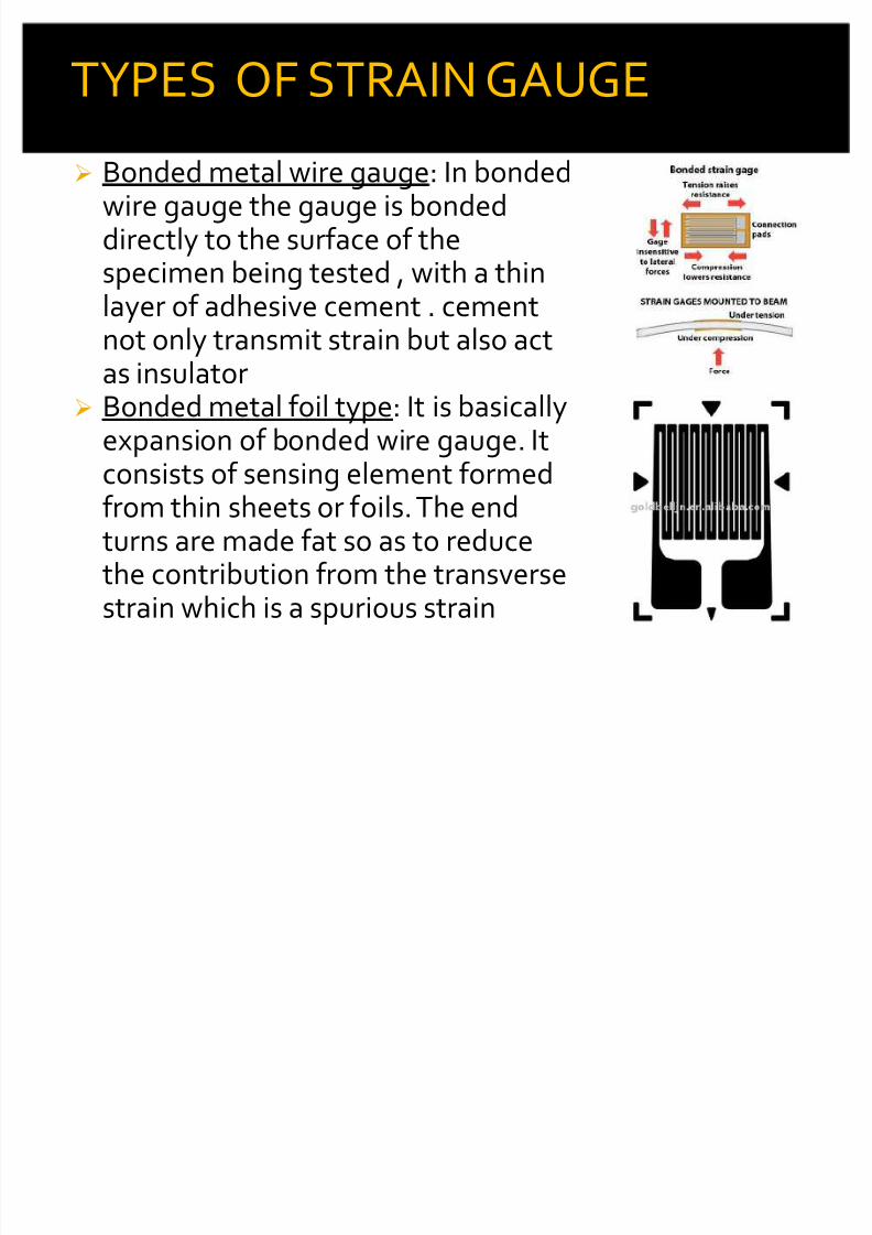
Un-bonded metal wire gauge: At theinitial preload the strain and
resistance of four wires are normallyequal which gives a balanced bridge.Application of motion increasestension in two wires and decreases intwo others causing corresponding
change in resistance so bridgebecome unbalanced and output isproportional to input motion
TYPES OF STRAIN GAUGE
8/6/2019 Displacement Measurement 2
http://slidepdf.com/reader/full/displacement-measurement-2 67/73
8/6/2019 Displacement Measurement 2
http://slidepdf.com/reader/full/displacement-measurement-2 68/73
Semiconductor type: The resistivity of dopedsilicon and germanium undergoes a changewhen stressed. This property is called piezo-resistivity is utilized to construct strain gaugewith these metals.
ADVANTAGES:1. No moving parts
2. These are small and inexpensiveDISADVANTAGES:1. Needs to be calibrated2. Usually they are nonlinear
TYPES OF STRAIN GAUGE
8/6/2019 Displacement Measurement 2
http://slidepdf.com/reader/full/displacement-measurement-2 69/73
8/6/2019 Displacement Measurement 2
http://slidepdf.com/reader/full/displacement-measurement-2 70/73
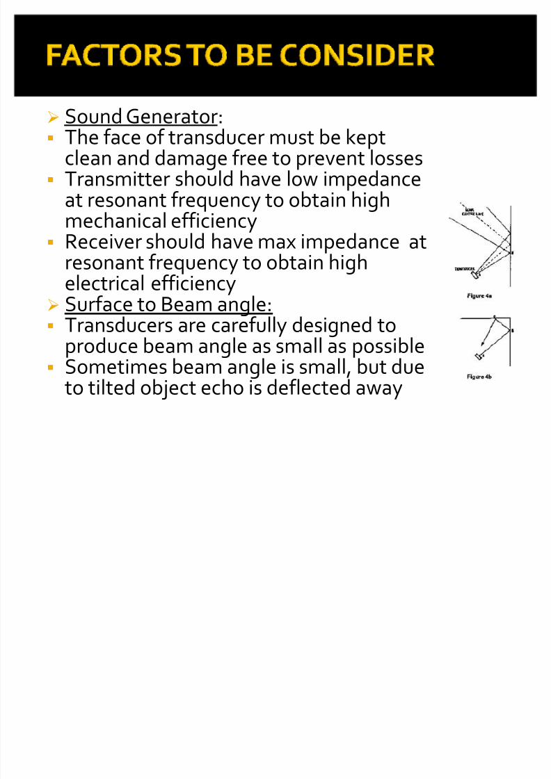
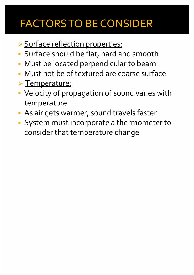
Sound Generator: The face of transducer must be kept
clean and damage free to prevent losses Transmitter should have low impedance
at resonant frequency to obtain highmechanical efficiency
Receiver should have max impedance atresonant frequency to obtain highelectrical efficiency
Surface to Beam angle: Transducers are carefully designed to
produce beam angle as small as possible Sometimes beam angle is small, but due
to tilted object echo is deflected away
8/6/2019 Displacement Measurement 2
http://slidepdf.com/reader/full/displacement-measurement-2 71/73
8/6/2019 Displacement Measurement 2
http://slidepdf.com/reader/full/displacement-measurement-2 72/73

8/6/2019 Displacement Measurement 2
http://slidepdf.com/reader/full/displacement-measurement-2 73/73