displacement ventilation - 15000 inc. · 2014-03-25 · displacement ventilation diffusers are...
TRANSCRIPT
DISPLACEMENT VENTILATION
www.titus-hvac.com | www.titus-energysolutions.com
A p p l i c a t i o n G u i d e
clever. creative. comfort.
Application Guide ...........................................................................................................................................3
Introduction to Displacement Ventilation ................................................................................................3
Air Change Effectiveness .........................................................................................................................3
Typical Applications .................................................................................................................................4
Contaminant Removal .............................................................................................................................4
Benefits & Limitations .............................................................................................................................4
Energy Considerations .............................................................................................................................4
Outlet Characteristics ..............................................................................................................................5
The Adjacent Zone ..................................................................................................................................5
Outlet Choices .........................................................................................................................................5
Heat Sources & Convective Flows ...........................................................................................................6
Space Temperature Gradients & Airflow Rates .......................................................................................6
Air Pattern Projection ..............................................................................................................................6
Methods of Evaluation.............................................................................................................................7
Supply Air Connections ...........................................................................................................................7
Acoustical Performance ...........................................................................................................................7
Displacement Ventilation Theory & Governing Equations .......................................................................7
Design Procedure for Displacement Ventilation ......................................................................................9
Design Examples ...................................................................................................................................10
References .............................................................................................................................................16
Displacement Ventilation
ww
w.titu
s-hvac.com
| ww
w.titu
s-energ
ysolu
tion
s.com
3
APPLICATION GUIDE
APPLICATION GUIDE
Displacement Ventilation Design & Application GuideBuildings come in all shapes and sizes and are designed for any number of purposes. In order to create healthy and productive environments, air distribution systems must be selected that best meet the goals of designers. There are a wide range of choices available, but often one system can be identified as the best solution in terms of cost, comfort and energy. The purpose of this guide is to explain how displacement ventilation works, describe recommended applications and provide engineering guidance to the system designer.
INTRODUCTION TO DISPLACEMENT VENTILATIONIn order to understand the advantages and limitations of displacement ventilation, it’s important to understand the differences between conventional mixed air distribution and fully-stratified air distribution.
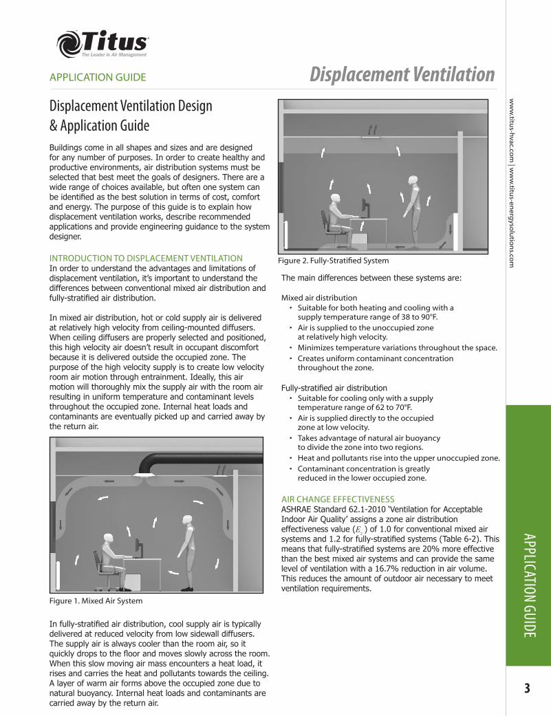
In mixed air distribution, hot or cold supply air is delivered at relatively high velocity from ceiling-mounted diffusers. When ceiling diffusers are properly selected and positioned, this high velocity air doesn’t result in occupant discomfort because it is delivered outside the occupied zone. The purpose of the high velocity supply is to create low velocity room air motion through entrainment. Ideally, this air motion will thoroughly mix the supply air with the room air resulting in uniform temperature and contaminant levels throughout the occupied zone. Internal heat loads and contaminants are eventually picked up and carried away by the return air.
In fully-stratified air distribution, cool supply air is typically delivered at reduced velocity from low sidewall diffusers. The supply air is always cooler than the room air, so it quickly drops to the floor and moves slowly across the room. When this slow moving air mass encounters a heat load, it rises and carries the heat and pollutants towards the ceiling. A layer of warm air forms above the occupied zone due to natural buoyancy. Internal heat loads and contaminants are carried away by the return air.
The main differences between these systems are:
Mixed air distribution • Suitable for both heating and cooling with a
supply temperature range of 38 to 90°F.• Air is supplied to the unoccupied zone
at relatively high velocity.• Minimizes temperature variations throughout the space.• Creates uniform contaminant concentration
throughout the zone.
Fully-stratified air distribution • Suitable for cooling only with a supply
temperature range of 62 to 70°F.• Air is supplied directly to the occupied
zone at low velocity.• Takes advantage of natural air buoyancy
to divide the zone into two regions.• Heat and pollutants rise into the upper unoccupied zone.• Contaminant concentration is greatly
reduced in the lower occupied zone.
AIR CHANGE EFFECTIVENESSASHRAE Standard 62.1-2010 ‘Ventilation for Acceptable Indoor Air Quality’ assigns a zone air distribution effectiveness value (Ez ) of 1.0 for conventional mixed air systems and 1.2 for fully-stratified systems (Table 6-2). This means that fully-stratified systems are 20% more effective than the best mixed air systems and can provide the same level of ventilation with a 16.7% reduction in air volume. This reduces the amount of outdoor air necessary to meet ventilation requirements.
Figure 1. Mixed Air System
Figure2.Fully-StratifiedSystem
Displacement Ventilation
4
ww
w.ti
tus-
hvac
.co
m |
ww
w.ti
tus-
ener
gys
olu
tio
ns.
com
APPL
ICAT
ION
GUID
E
APPLICATION GUIDE
TYPICAL APPLICATIONSIdeal applications for displacement ventilation often involve large open spaces with tall ceilings. These include but are not limited to:• Theaters and performance halls• Meeting rooms and lecture halls• Restaurants and cafeterias• Hotel lobbies and atriums• Shopping malls• Gymnasiums• Casinos• Museums and exhibit halls• Classrooms• Airport terminals and train stations
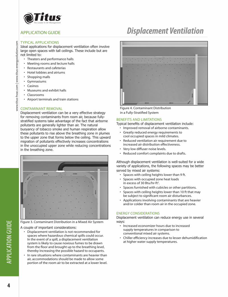
CONTAMINANT REMOVALDisplacement ventilation can be a very effective strategy for removing contaminants from room air, because fully-stratified systems take advantage of the fact that airborne pollutants are generally lighter than air. The natural buoyancy of tobacco smoke and human respiration allow these pollutants to rise above the breathing zone in plumes to the upper zone that forms below the ceiling. This upward migration of pollutants effectively increases concentrations in the unoccupied upper zone while reducing concentrations in the breathing zone.
A couple of important considerations:• Displacement ventilation is not recommended for
spaces where hazardous chemical spills could occur. In the event of a spill, a displacement ventilation system is likely to cause noxious fumes to be drawn fromthefloorandbroughtuptothebreathinglevel,thereby increasing the possible hazard to occupants.
• In rare situations where contaminants are heavier than air, accommodations should be made to allow some portion of the room air to be extracted at a lower level.
BENEFITS AND LIMITATIONSTypical benefits of displacement ventilation include:• Improved removal of airborne contaminants.• Greatly reduced energy requirements to
cool occupied spaces in mild climates.• Reduced ventilation air requirement due to
increased air distribution effectiveness.• Very low diffuser noise levels.• Reduced comfort complaints due to drafts.
Although displacement ventilation is well-suited for a wide variety of applications, the following spaces may be better served by mixed air systems:• Spaces with ceiling heights lower than 9 ft.• Spaces with occupied zone heat loads
in excess of 30 Btu/hr-ft2.• Spaces furnished with cubicles or other partitions.• Spaces with ceiling heights lower than 10 ft that may besubjecttosignificantroomairdisturbances.
• Applications involving contaminants that are heavier and/or colder than room air in the occupied zone.
ENERGY CONSIDERATIONSDisplacement ventilation can reduce energy use in several ways:• Increased economizer hours due to increased
supply temperatures in comparison to conventional mixed air systems.
• Chillerefficiencyincreasesduetolesserdehumidificationat higher water supply temperatures.
Figure 3. Contaminant Distribution in a Mixed Air System
Figure 4. Contaminant Distribution inaFully-StratifiedSystem
Displacement Ventilation
ww
w.titu
s-hvac.com
| ww
w.titu
s-energ
ysolu
tion
s.com
5
APPLICATION GUIDE
APPLICATION GUIDE
OUTLET CHARACTERISTICSDisplacement ventilation requires outlets that supply air at extremely low velocities, (typically 50-70 fpm). These outlets are typically located low on a sidewall or at the base of a column. The low average face velocity generally results in rather large diffuser panels. Since the outlets are located adjacent to the occupied zone and within easy reach of room occupants, they have the following special requirements:• Shouldbeelevatedabovethefloortoprevent
damage from cleaning equipment.• Constructionandfinishesmustberugged
enough to prevent damage through accidental or intentional occupant contact.
• Should provide a concealed and tamperproof means of air pattern adjustment.
• Face panel must be removable for cleaning and adjustment of air pattern controllers.
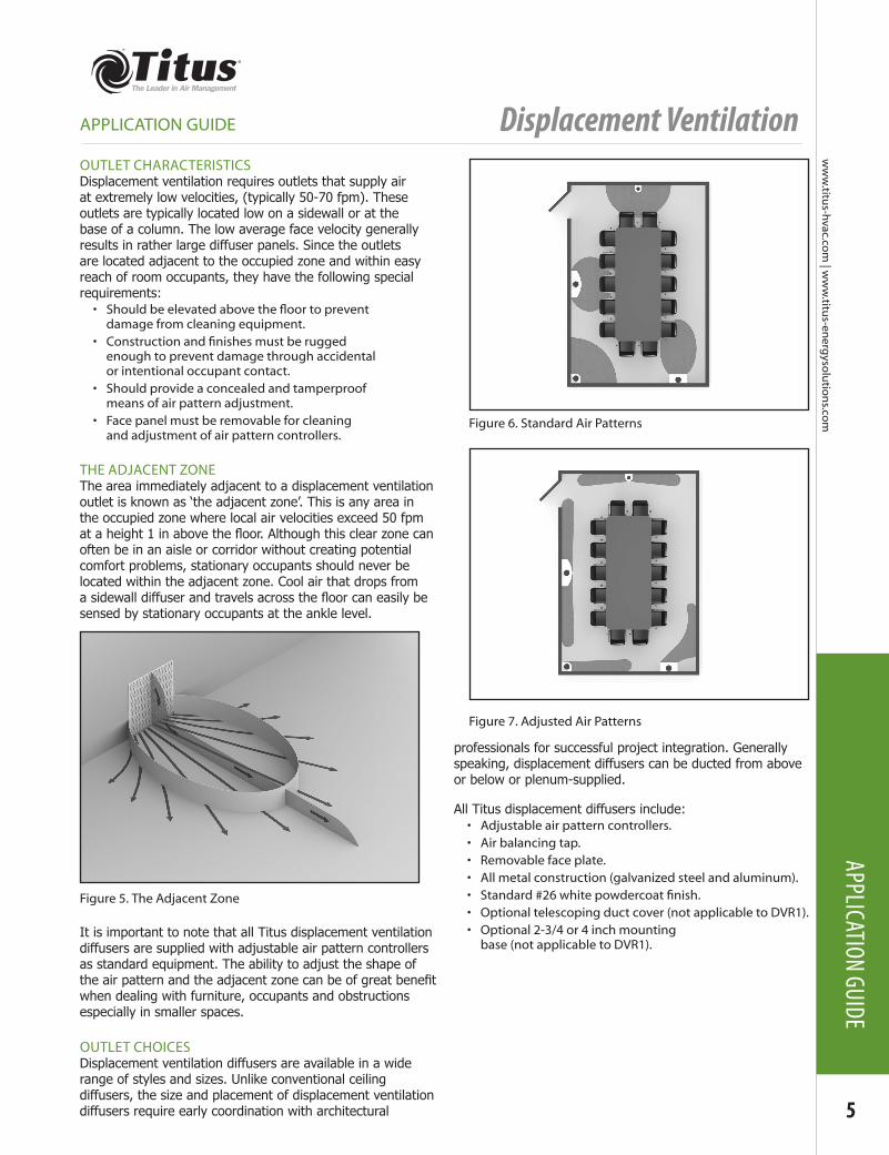
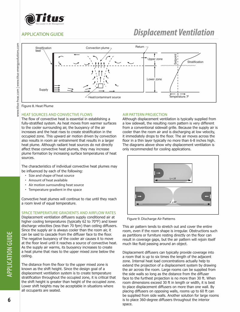
THE ADJACENT ZONEThe area immediately adjacent to a displacement ventilation outlet is known as ‘the adjacent zone’. This is any area in the occupied zone where local air velocities exceed 50 fpm at a height 1 in above the floor. Although this clear zone can often be in an aisle or corridor without creating potential comfort problems, stationary occupants should never be located within the adjacent zone. Cool air that drops from a sidewall diffuser and travels across the floor can easily be sensed by stationary occupants at the ankle level.
It is important to note that all Titus displacement ventilation diffusers are supplied with adjustable air pattern controllers as standard equipment. The ability to adjust the shape of the air pattern and the adjacent zone can be of great benefit when dealing with furniture, occupants and obstructions especially in smaller spaces.
OUTLET CHOICESDisplacement ventilation diffusers are available in a wide range of styles and sizes. Unlike conventional ceiling diffusers, the size and placement of displacement ventilation diffusers require early coordination with architectural
professionals for successful project integration. Generally speaking, displacement diffusers can be ducted from above or below or plenum-supplied.
All Titus displacement diffusers include:• Adjustable air pattern controllers.• Air balancing tap. • Removable face plate.• All metal construction (galvanized steel and aluminum).• Standard#26whitepowdercoatfinish.• Optional telescoping duct cover (not applicable to DVR1).• Optional 2-3/4 or 4 inch mounting
base (not applicable to DVR1).
Figure 6. Standard Air Patterns
Figure 7. Adjusted Air Patterns
Figure 5. The Adjacent Zone
Displacement Ventilation
6
ww
w.ti
tus-
hvac
.co
m |
ww
w.ti
tus-
ener
gys
olu
tio
ns.
com
APPL
ICAT
ION
GUID
E
APPLICATION GUIDE
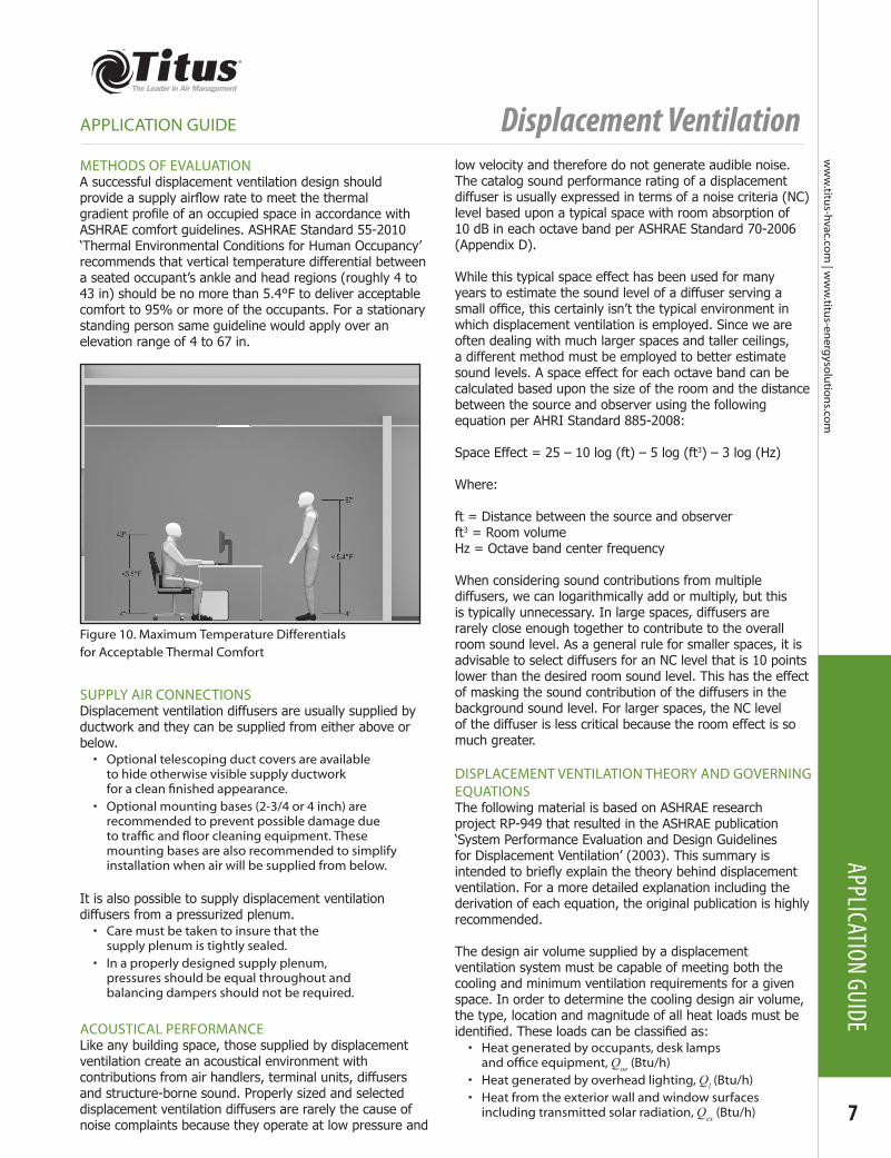
Figure 8. Heat Plume
Stratificationlevel
Upper zone
Convection plume Return
Lower zone
Heat/contaminant source Temperature, °F
StratificationSet
poin
t
Supply0
HEAT SOURCES AND CONVECTIVE FLOWSThe flow of convective heat is essential in establishing a fully-stratified system. As heat moves from warmer surfaces to the cooler surrounding air, the buoyancy of the air increases and the heat rises to create stratification in the occupied zone. This upward air motion driven by convection also results in room air entrainment that results in a larger heat plume. Although radiant heat sources do not directly affect these convective heat plumes, they may increase plume formation by increasing surface temperatures of heat sources.
The characteristics of individual convective heat plumes may be influenced by each of the following:• Size and shape of heat source• Amount of heat available• Air motion surrounding heat source• Temperature gradient in the space
Convective heat plumes will continue to rise until they reach a room level of equal temperature.
SPACE TEMPERATURE GRADIENTS AND AIRFLOW RATESDisplacement ventilation diffusers supply conditioned air at higher cooling temperatures (typically 62 to 70°F) and lower discharge velocities (less than 70 fpm) than ceiling diffusers. Since the supply air is always cooler than the room air, it can be said to cascade from the diffuser face to the floor. The negative buoyancy of the cooler air causes it to move at the floor level until it reaches a source of convective heat. As the supply air warms, its buoyancy increases to create a heat plume that rises to the upper mixed zone below the ceiling.
The distance from the floor to the upper mixed zone is known as the shift height. Since the design goal of a displacement ventilation system is to create temperature stratification throughout the occupied zone, it is critical that the shift height is greater than height of the occupied zone. Lower shift heights may be acceptable in situations where all occupants are seated.
AIR PATTERN PROJECTIONAlthough displacement ventilation is typically supplied from a low sidewall, the resulting room pattern is very different from a conventional sidewall grille. Because the supply air is cooler than the room air and is discharging at low velocity, it immediately drops to the floor. The air moves across the floor in a thin layer typically no more than 6-8 inches high. The diagrams above show why displacement ventilation is only recommended for cooling applications.
This air pattern tends to stretch out and cover the entire room, even if the room shape is irregular. Obstructions such as partitions or furniture resting directly on the floor can result in coverage gaps, but the air pattern will rejoin itself much like fluid passing around an object.
Displacement diffusers can typically provide coverage into a room that is up to six times the length of the adjacent zone. Internal heat load concentrations actually help to extend the projection of a displacement system by drawing the air across the room. Large rooms can be supplied from the side walls so long as the distance from the diffuser face to the furthest projection is no more than 30 ft. When room dimensions exceed 30 ft in length or width, it is best to place displacement diffusers on more than one wall. By placing diffusers on opposing walls, rooms up to 60 ft can be supplied from side walls. Another solution for large rooms is to place 360-degree diffusers throughout the interior space.
Figure 9. Discharge Air Patterns
Displacement Ventilation
ww
w.titu
s-hvac.com
| ww
w.titu
s-energ
ysolu
tion
s.com
7
APPLICATION GUIDE
APPLICATION GUIDE
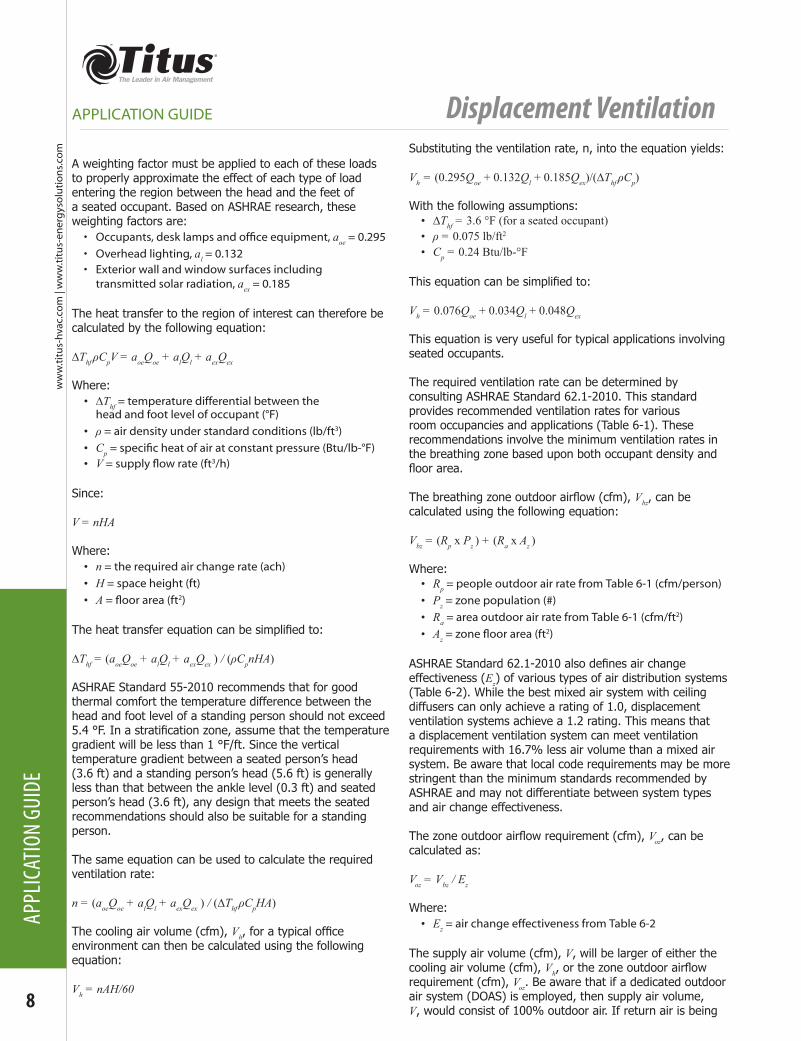
METHODS OF EVALUATIONA successful displacement ventilation design should provide a supply airflow rate to meet the thermal gradient profile of an occupied space in accordance with ASHRAE comfort guidelines. ASHRAE Standard 55-2010 ‘Thermal Environmental Conditions for Human Occupancy’ recommends that vertical temperature differential between a seated occupant’s ankle and head regions (roughly 4 to 43 in) should be no more than 5.4°F to deliver acceptable comfort to 95% or more of the occupants. For a stationary standing person same guideline would apply over an elevation range of 4 to 67 in.
SUPPLY AIR CONNECTIONSDisplacement ventilation diffusers are usually supplied by ductwork and they can be supplied from either above or below. • Optional telescoping duct covers are available
to hide otherwise visible supply ductwork foracleanfinishedappearance.
• Optional mounting bases (2-3/4 or 4 inch) are recommended to prevent possible damage due totrafficandfloorcleaningequipment.Thesemounting bases are also recommended to simplify installation when air will be supplied from below.
It is also possible to supply displacement ventilation diffusers from a pressurized plenum.• Care must be taken to insure that the
supply plenum is tightly sealed.• In a properly designed supply plenum,
pressures should be equal throughout and balancing dampers should not be required.
ACOUSTICAL PERFORMANCELike any building space, those supplied by displacement ventilation create an acoustical environment with contributions from air handlers, terminal units, diffusers and structure-borne sound. Properly sized and selected displacement ventilation diffusers are rarely the cause of noise complaints because they operate at low pressure and
low velocity and therefore do not generate audible noise. The catalog sound performance rating of a displacement diffuser is usually expressed in terms of a noise criteria (NC) level based upon a typical space with room absorption of 10 dB in each octave band per ASHRAE Standard 70-2006 (Appendix D).
While this typical space effect has been used for many years to estimate the sound level of a diffuser serving a small office, this certainly isn’t the typical environment in which displacement ventilation is employed. Since we are often dealing with much larger spaces and taller ceilings, a different method must be employed to better estimate sound levels. A space effect for each octave band can be calculated based upon the size of the room and the distance between the source and observer using the following equation per AHRI Standard 885-2008:
Space Effect = 25 – 10 log (ft) – 5 log (ft3) – 3 log (Hz)
Where:
ft = Distance between the source and observerft3 = Room volumeHz = Octave band center frequency
When considering sound contributions from multiple diffusers, we can logarithmically add or multiply, but this is typically unnecessary. In large spaces, diffusers are rarely close enough together to contribute to the overall room sound level. As a general rule for smaller spaces, it is advisable to select diffusers for an NC level that is 10 points lower than the desired room sound level. This has the effect of masking the sound contribution of the diffusers in the background sound level. For larger spaces, the NC level of the diffuser is less critical because the room effect is so much greater.
DISPLACEMENT VENTILATION THEORY AND GOVERNING EQUATIONSThe following material is based on ASHRAE research project RP-949 that resulted in the ASHRAE publication ‘System Performance Evaluation and Design Guidelines for Displacement Ventilation’ (2003). This summary is intended to briefly explain the theory behind displacement ventilation. For a more detailed explanation including the derivation of each equation, the original publication is highly recommended.
The design air volume supplied by a displacement ventilation system must be capable of meeting both the cooling and minimum ventilation requirements for a given space. In order to determine the cooling design air volume, the type, location and magnitude of all heat loads must be identified. These loads can be classified as:• Heat generated by occupants, desk lamps andofficeequipment,Qoe (Btu/h)
• Heat generated by overhead lighting, Ql (Btu/h)• Heat from the exterior wall and window surfaces
including transmitted solar radiation, Qex (Btu/h)
Figure 10. Maximum Temperature Differentials for Acceptable Thermal Comfort
Displacement Ventilation
8
ww
w.ti
tus-
hvac
.co
m |
ww
w.ti
tus-
ener
gys
olu
tio
ns.
com
APPL
ICAT
ION
GUID
E
APPLICATION GUIDE
A weighting factor must be applied to each of these loads to properly approximate the effect of each type of load entering the region between the head and the feet of a seated occupant. Based on ASHRAE research, these weighting factors are:• Occupants,desklampsandofficeequipment,аoe = 0.295• Overhead lighting, аl = 0.132• Exterior wall and window surfaces including
transmitted solar radiation, аex = 0.185
The heat transfer to the region of interest can therefore be calculated by the following equation:
∆Thf ρCpV = аoeQoe + аlQl + аexQex
Where:• ∆Thf = temperature differential between the
head and foot level of occupant (°F)• ρ = air density under standard conditions (lb/ft3)• Cp=specificheatofairatconstantpressure(Btu/lb-°F)• V=supplyflowrate(ft3/h)
Since:
V = nHA
Where:• n = the required air change rate (ach)• H = space height (ft)• A=floorarea(ft2)
The heat transfer equation can be simplified to:
∆Thf = (аoeQoe + аlQl + аexQex ) / (ρCpnHA)
ASHRAE Standard 55-2010 recommends that for good thermal comfort the temperature difference between the head and foot level of a standing person should not exceed 5.4 °F. In a stratification zone, assume that the temperature gradient will be less than 1 °F/ft. Since the vertical temperature gradient between a seated person’s head (3.6 ft) and a standing person’s head (5.6 ft) is generally less than that between the ankle level (0.3 ft) and seated person’s head (3.6 ft), any design that meets the seated recommendations should also be suitable for a standing person.
The same equation can be used to calculate the required ventilation rate:
n = (аoeQoe + аlQl + аexQex ) / (∆Thf ρCpHA)
The cooling air volume (cfm), Vh, for a typical office environment can then be calculated using the following equation:
Vh = nAH/60
Substituting the ventilation rate, n, into the equation yields:
Vh = (0.295Qoe + 0.132Ql + 0.185Qex)/(∆Thf ρCp)
With the following assumptions:• ∆Thf = 3.6 °F (for a seated occupant)• ρ = 0.075 lb/ft2
• Cp = 0.24 Btu/lb-°F
This equation can be simplified to:
Vh = 0.076Qoe + 0.034Ql + 0.048Qex
This equation is very useful for typical applications involving seated occupants.
The required ventilation rate can be determined by consulting ASHRAE Standard 62.1-2010. This standard provides recommended ventilation rates for various room occupancies and applications (Table 6-1). These recommendations involve the minimum ventilation rates in the breathing zone based upon both occupant density and floor area.
The breathing zone outdoor airflow (cfm), Vbz, can be calculated using the following equation:
Vbz = (Rp x Pz ) + (Ra x Az )
Where:• Rp = people outdoor air rate from Table 6-1 (cfm/person) • Pz = zone population (#)• Ra = area outdoor air rate from Table 6-1 (cfm/ft2) • Az=zonefloorarea(ft
2)
ASHRAE Standard 62.1-2010 also defines air change effectiveness (Ez) of various types of air distribution systems (Table 6-2). While the best mixed air system with ceiling diffusers can only achieve a rating of 1.0, displacement ventilation systems achieve a 1.2 rating. This means that a displacement ventilation system can meet ventilation requirements with 16.7% less air volume than a mixed air system. Be aware that local code requirements may be more stringent than the minimum standards recommended by ASHRAE and may not differentiate between system types and air change effectiveness.
The zone outdoor airflow requirement (cfm), Voz, can be calculated as:
Voz = Vbz / Ez
Where:• Ez = air change effectiveness from Table 6-2
The supply air volume (cfm), V, will be larger of either the cooling air volume (cfm), Vh, or the zone outdoor airflow requirement (cfm), Voz. Be aware that if a dedicated outdoor air system (DOAS) is employed, then supply air volume, V, would consist of 100% outdoor air. If return air is being
Displacement Ventilation
ww
w.titu
s-hvac.com
| ww
w.titu
s-energ
ysolu
tion
s.com
9
APPLICATION GUIDE
APPLICATION GUIDE
mixed with outdoor air, supply air volume, V, must contain enough outdoor air to meet the zone outdoor requirement, Voz.
The supply air temperature, Ts, is always cooler than the room temperature, Tsp, and can be calculated by based on the air temperature at the floor level, Tf.
Tf = Tsp - ∆Thf
And:
Ts = Tf – θfQt / (60ρCpV)
Where:• θf = dimensionless temperature calculated
by Mundt’s formula (1992)• Qt = total cooling load in space (Btu/h)• V = supply air volume (cfm)
θf = 1 / ((60VρCp / A)((1/αr ) + (1/αcf )) + 1)
Where:• αr=radiantheattransferfromceilingtofloor(Btu/h-ft
2-°F)• αcf=convectiveheattransferfromfloor
surface to the room air (Btu/h-ft2-°F)
Assuming that heat transfer coefficients αr and αcf are equal to 0.9 Btu/(h-ft2-°F) and that Thf should be less than 3.6BF for a seated occupant, this equation can then be simplified to:
Ts = Tsp – 3.6 – ((AQt )/(2.59V2 + 1.08 AV))
The exhaust air temperature, Te, can be calculated as:
Te = Ts + ((Qt )/(1.08V))
DESIGN PROCEDURE FOR DISPLACEMENT VENTILATIONThe following design procedure is patterned on that provided in an ASHRAE publication entitled ‘System Performance and Design Guidelines for Displacement Ventilation’ (2003). It was developed based upon the finding of ASHRAE Research Project RP-949.
Step 1 – Calculate the Total Cooling LoadThe total cooling load, Qt, is the sum of the heat loads:
Qt = Qoe + Ql + Qex
Where:• Qoe = Heat generated by occupants, desk lampsandofficeequipment(Btu/h)
• Ql = Heat generated by overhead lighting (Btu/h)• Qex = Heat from the exterior wall and window surfaces
including transmitted solar radiation (Btu/h)
Step 2 – Check for Excessive Heat LoadDisplacement ventilation is generally not recommended for
internal heat loads greater than 30 Btu/ft2.
Qt / A ≤ 30 Btu/ft2
A = L x W
Where:• A=floorarea(ft2)• L = room length (ft)• W = room width (ft)
Step 3 – Calculate the Cooling Air VolumeThe cooling air volume, Vh, can be determined from heat loads with weighting factors applied:
Vh = 0.076Qoe + 0.034Ql + 0.048Qex
Step 4 – Calculate the Zone Outdoor Airflow for Acceptable Indoor Air QualityThe zone outdoor airflow requirement (cfm), Voz, and the breathing zone outdoor airflow (cfm), Vbz, can be determined from ASHRAE Standard 62.1 (Tables 6-1 and 6-2) and the following equations:
Vbz = (Rp x Pz ) + (Ra x Az )
Where:• Rp = people outdoor air rate from Table 6-1 (cfm/person) • Pz = zone population (#)• Ra = area outdoor air rate from Table 6-1 (cfm/ft2) • Az=zonefloorarea(ft
2)
Voz = Vbz / Ez
Where:• Ez = air change effectiveness from Table 6-2 = 1.2
Step 5 – Determine the Supply Air VolumeThe supply air volume, V, will be larger of either the cooling air volume, Vh, or the zone outdoor airflow requirement, Voz.
Step 6 – Calculate the Supply Air TemperatureThe supply air temperature, Ts, can be calculated as:
Ts = Tsp – 3.6 – ((AQt )/(2.59V2 + 1.08 AV))
Where:• Tsp = room temperature (°F)
Step 7 – Calculate the Exhaust Air TemperatureThe exhaust air temperature, Te, can be calculated as:
Te = Ts + ((Qt )/(1.08V))
Step 8 – Select Supply Diffuser(s)
Displacement Ventilation
10
ww
w.ti
tus-
hvac
.co
m |
ww
w.ti
tus-
ener
gys
olu
tio
ns.
com
APPL
ICAT
ION
GUID
E
APPLICATION GUIDE
DESIGN EXAMPLE - PRIVATE PERIMETER OFFICEThis a small private office measuring 12 ft by 10 ft by 9 ft (L x W x H). The office is equipped with a computer, a monitor, a small printer and a desk lamp. The 12 ft long wall includes exterior glass. The room will be supplied by a dedicated outdoor air system (DOAS). Assume:• Occupancy = 1• Load per person = 250 Btu/h • Overhead lighting load = 2 watts/ft2 = 6.826 Btu/h-ft2
• Computer load = 65 watts = 222 Btu/h• Monitor load = 30 watts = 102 Btu/h• Small printer load = 30 watts = 102 Btu/h• Desk lamp load = 40 watts = 137 Btu/h• Solar and glass load = 4.0 Btu/h-ft2
Step 1 – Calculate the Total Cooling LoadQt = Qoe + Ql + Qex
Where:• Qoe = Heat generated by occupants, desk lampsandofficeequipment(Btu/h)
• Ql = Heat generated by overhead lighting (Btu/h)• Qex = Heat from the exterior wall and window surfaces
including transmitted solar radiation (Btu/h)
Qoe = person + computer + monitor + small printer + desk lamp = 813 Btu/hQl = overhead lighting load x floor area = 819 Btu/hQex = solar and glass load x exterior wall area = 432 Btu/h
Qt = 2064 Btu/h
Step 2 – Check for Excessive Heat LoadDisplacement ventilation is generally not recommended for internal heat loads greater than 30 Btu/ft2.
Qt / A ≤ 30 Btu/ft2
A = L x W
Where:• A=floorarea(ft2)• L = room length (ft)• W = room width (ft)
Qt / A = 17.2 Btu/ft2
Step 3 – Calculate the Cooling Air VolumeThe cooling air volume, Vh, can be determined from heat loads with weighting factors applied:
Vh = 0.076Qoe + 0.034Ql + 0.048Qex
Vh = 110 cfm
Step 4 – Calculate the Zone Outdoor Airflow for Acceptable Indoor Air QualityThe zone outdoor airflow requirement (cfm), Voz, and the
breathing zone outdoor airflow (cfm), Vbz, can be determined from ASHRAE Standard 62.1 (Tables 6-1 and 6-2) and the following equations:
Vbz = (Rp x Pz ) + (Ra x Az )
Where:• Rp = people outdoor air rate from
Table 6-1 = 5.0 cfm/person• Pz = zone population (#) = 1• Ra = area outdoor air rate from Table 6-1 = 0.06 cfm/ft2
• Az=zonefloorarea(ft2)
Vbz = 12.2 cfm
Voz = Vbz / Ez
Where:• Ez = air change effectiveness from Table 6-2 = 1.2
Voz = 10.2 cfm
Step 5 – Determine the Supply Air VolumeThe supply air volume, V, will be larger of either the cooling air volume, Vh, or the zone outdoor airflow requirement, Voz.
V = 110 cfm
Step 6 – Calculate the Supply Air TemperatureThe supply air temperature, Ts, can be calculated as:
Ts = Tsp – 3.6 – ((AQt )/(2.59V2 + 1.08 AV))
Where:• Tsp = room temperature = 72 °F
Ts = 63 °F
Step 7 – Calculate the Exhaust Air TemperatureThe exhaust air temperature, Te, can be calculated as:
Te = Ts + ((Qt )/(1.08V))
Te = 80 °F
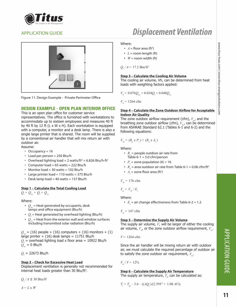
Step 8 – Select Supply Diffuser(s)The best diffuser for this application would be a single flush-mounted wall unit handling 110 cfm. It should ideally be located away from the desk on an opposite wall discharging parallel to the window. Care should be taken in a space this size to ensure that the depth of the adjacent zone is less than 3-4 ft. Since the sound level in a private office is recommended not to exceed a sound level of NC35, the diffuser should be selected for NC25 or less. See Figure 11 for example of diffuser layout.
Displacement Ventilation
ww
w.titu
s-hvac.com
| ww
w.titu
s-energ
ysolu
tion
s.com
11
APPLICATION GUIDE
APPLICATION GUIDE
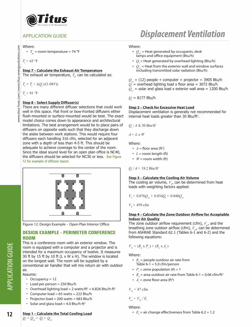
DESIGN EXAMPLE - OPEN PLAN INTERIOR OFFICEThis is an open plan office for customer service representatives. The office is furnished with workstations to accommodate up to sixteen employees and measures 40 ft by 40 ft by 12 ft (L x W x H). Each workstation is equipped with a computer, a monitor and a desk lamp. There is also a single large printer that is shared. The room will be supplied by a conventional air handler that will mix return air with outdoor air. Assume:• Occupancy = 16• Load per person = 250 Btu/h • Overhead lighting load = 2 watts/ft2 = 6.826 Btu/h-ft2
• Computer load = 65 watts = 222 Btu/h• Monitor load = 30 watts = 102 Btu/h• Large printer load = 110 watts = 375 Btu/h• Desk lamp load = 40 watts = 137 Btu/h
Step 1 – Calculate the Total Cooling LoadQt = Qoe + Ql + Qex
Where:• Qoe = Heat generated by occupants, desk lampsandofficeequipment(Btu/h)
• Ql = Heat generated by overhead lighting (Btu/h)• Qex = Heat from the exterior wall and window surfaces
including transmitted solar radiation (Btu/h)
Qoe = (16) people + (16) computers + (16) monitors + (1) large printer + (16) desk lamps = 11751 Btu/hQl = overhead lighting load x floor area = 10922 Btu/hQex = 0 Btu/h
Qt = 22673 Btu/h
Step 2 – Check for Excessive Heat LoadDisplacement ventilation is generally not recommended for internal heat loads greater than 30 Btu/ft2.
Qt / A ≤ 30 Btu/ft2
A = L x W
Where:• A=floorarea(ft2)• L = room length (ft)• W = room width (ft)
Qt / A = 17.2 Btu/ft2
Step 3 – Calculate the Cooling Air VolumeThe cooling air volume, Vh, can be determined from heat loads with weighting factors applied:
Vh = 0.076Qoe + 0.034Ql + 0.048Qex
Vh = 1264 cfm
Step 4 – Calculate the Zone Outdoor Airflow for Acceptable Indoor Air QualityThe zone outdoor airflow requirement (cfm), Voz, and the breathing zone outdoor airflow (cfm), Vbz, can be determined from ASHRAE Standard 62.1 (Tables 6-1 and 6-2) and the following equations:
Vbz = (Rp x Pz ) + (Ra x Az )
Where:• Rp = people outdoor air rate from
Table 6-1 = 5.0 cfm/person• Pz = zone population (#) = 16• Ra = area outdoor air rate from Table 6-1 = 0.06 cfm/ft2
• Az=zonefloorarea(ft2)
Vbz = 176 cfm
Voz = Vbz / Ez
Where:• Ez = air change effectiveness from Table 6-2 = 1.2
Voz = 147 cfm
Step 5 – Determine the Supply Air VolumeThe supply air volume, V, will be larger of either the cooling air volume, Vh, or the zone outdoor airflow requirement, Voz.
V = 1264 cfm
Since the air handler will be mixing return air with outdoor air, we must calculate the required percentage of outdoor air to satisfy the zone outdoor air requirement, Voz.
Voz / V = 12%
Step 6 – Calculate the Supply Air TemperatureThe supply air temperature, Ts, can be calculated as:
Ts = Tsp – 3.6 – ((AQt )/(2.59V2 + 1.08 AV))
Figure11.DesignExample-PrivatePerimeterOffice
Displacement Ventilation
12
ww
w.ti
tus-
hvac
.co
m |
ww
w.ti
tus-
ener
gys
olu
tio
ns.
com
APPL
ICAT
ION
GUID
E
APPLICATION GUIDE
Where:• Tsp = room temperature = 74 °F
Ts = 65 °F
Step 7 – Calculate the Exhaust Air TemperatureThe exhaust air temperature, Te, can be calculated as:
Te = Ts + ((Qt )/(1.08V))
Te = 81 °F
Step 8 – Select Supply Diffuser(s)There are many different diffuser selections that could work well in this space. Flat front or bow-fronted diffusers either flush-mounted or surface-mounted would be best. The exact model choice comes down to appearance and architectural limitations. The best arrangement would be to place pairs of diffusers on opposite walls such that they discharge down the aisles between work stations. This would require four diffusers each handling 316 cfm, selected for an adjacent zone with a depth of less than 4-5 ft. This should be adequate to achieve coverage to the center of the room. Since the ideal sound level for an open plan office is NC40, the diffusers should be selected for NC30 or less. See Figure 12 for example of diffuser layout.
DESIGN EXAMPLE - PERIMETER CONFERENCE ROOMThis is a conference room with an exterior window. The room is equipped with a computer and a projector and is intended for a maximum occupancy of twelve. It measures 30 ft by 15 ft by 10 ft (L x W x H). The window is located on the longest wall. The room will be supplied by a conventional air handler that will mix return air with outdoor air. Assume:• Occupancy = 12• Load per person = 250 Btu/h • Overhead lighting load = 2 watts/ft2 = 6.826 Btu/h-ft2
• Computer load = 65 watts = 222 Btu/h • Projector load = 200 watts = 683 Btu/h• Solar and glass load = 4.0 Btu/h-ft2
Step 1 – Calculate the Total Cooling LoadQt = Qoe + Ql + Qex
Where:• Qoe = Heat generated by occupants, desk lampsandofficeequipment(Btu/h)
• Ql = Heat generated by overhead lighting (Btu/h)• Qex = Heat from the exterior wall and window surfaces
including transmitted solar radiation (Btu/h)
Qoe = (12) people + computer + projector = 3905 Btu/hQl = overhead lighting load x floor area = 3072 Btu/hQex = solar and glass load x exterior wall area = 1200 Btu/h
Qt = 8177 Btu/h
Step 2 – Check for Excessive Heat LoadDisplacement ventilation is generally not recommended for internal heat loads greater than 30 Btu/ft2.
Qt / A ≤ 30 Btu/ft2
A = L x W
Where:• A=floorarea(ft2)• L = room length (ft)• W = room width (ft)
Qt / A = 18.2 Btu/ft2
Step 3 – Calculate the Cooling Air VolumeThe cooling air volume, Vh, can be determined from heat loads with weighting factors applied:
Vh = 0.076Qoe + 0.034Ql + 0.048Qex
Vh = 459 cfm
Step 4 – Calculate the Zone Outdoor Airflow for Acceptable Indoor Air QualityThe zone outdoor airflow requirement (cfm), Voz, and the breathing zone outdoor airflow (cfm), Vbz, can be determined from ASHRAE Standard 62.1 (Tables 6-1 and 6-2) and the following equations:
Vbz = (Rp x Pz ) + (Ra x Az )
Where:• Rp = people outdoor air rate from
Table 6-1 = 5.0 cfm/person• Pz = zone population (#) = 1• Ra = area outdoor air rate from Table 6-1 = 0.06 cfm/ft2
• Az=zonefloorarea(ft2)
Vbz = 87 cfm
Voz = Vbz / Ez
Where:• Ez = air change effectiveness from Table 6.2 = 1.2
Figure12.DesignExample-OpenPlanInteriorOffice
Displacement Ventilation
ww
w.titu
s-hvac.com
| ww
w.titu
s-energ
ysolu
tion
s.com
13
APPLICATION GUIDE
APPLICATION GUIDE
Voz = 72.5 cfm
Step 5 – Determine the Supply Air VolumeThe supply air volume, V, will be larger of either the cooling air volume, Vh, or the zone outdoor airflow requirement, Voz.
V = 459 cfm
Since the air handler will be mixing return air with outdoor air, we must calculate the required percentage of outdoor air to satisfy the zone outdoor air requirement, Voz.
Voz / V = 16%
Step 6 – Calculate the Supply Air TemperatureThe supply air temperature, Ts, can be calculated as:
Ts = Tsp – 3.6 – ((AQt )/(2.59V2 + 1.08 AV))
Where:• Tsp = room temperature = 72 °F
Ts = 64 °F
Step 7 – Calculate the Exhaust Air TemperatureThe exhaust air temperature, Te, can be calculated as:
Te = Ts + ((Qt )/(1.08V))
Te = 80 °F
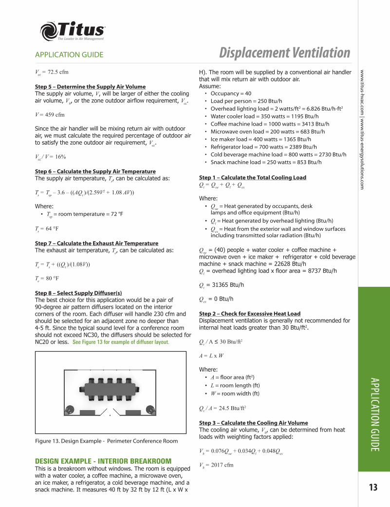
Step 8 – Select Supply Diffuser(s)The best choice for this application would be a pair of 90-degree air pattern diffusers located on the interior corners of the room. Each diffuser will handle 230 cfm and should be selected for an adjacent zone no deeper than 4-5 ft. Since the typical sound level for a conference room should not exceed NC30, the diffusers should be selected for NC20 or less. See Figure 13 for example of diffuser layout.
DESIGN EXAMPLE - INTERIOR BREAKROOMThis is a breakroom without windows. The room is equipped with a water cooler, a coffee machine, a microwave oven, an ice maker, a refrigerator, a cold beverage machine, and a snack machine. It measures 40 ft by 32 ft by 12 ft (L x W x
H). The room will be supplied by a conventional air handler that will mix return air with outdoor air. Assume:• Occupancy = 40• Load per person = 250 Btu/h • Overhead lighting load = 2 watts/ft2 = 6.826 Btu/h-ft2
• Water cooler load = 350 watts = 1195 Btu/h• Coffee machine load = 1000 watts = 3413 Btu/h • Microwave oven load = 200 watts = 683 Btu/h • Ice maker load = 400 watts = 1365 Btu/h• Refrigerator load = 700 watts = 2389 Btu/h• Cold beverage machine load = 800 watts = 2730 Btu/h• Snack machine load = 250 watts = 853 Btu/h
Step 1 – Calculate the Total Cooling LoadQt = Qoe + Ql + Qex
Where:• Qoe = Heat generated by occupants, desk lampsandofficeequipment(Btu/h)
• Ql = Heat generated by overhead lighting (Btu/h)• Qex = Heat from the exterior wall and window surfaces
including transmitted solar radiation (Btu/h)
Qoe = (40) people + water cooler + coffee machine + microwave oven + ice maker + refrigerator + cold beverage machine + snack machine = 22628 Btu/hQl = overhead lighting load x floor area = 8737 Btu/h
Qt = 31365 Btu/h
Qex = 0 Btu/h
Step 2 – Check for Excessive Heat LoadDisplacement ventilation is generally not recommended for internal heat loads greater than 30 Btu/ft2.
Qt / A ≤ 30 Btu/ft2
A = L x W
Where:• A=floorarea(ft2)• L = room length (ft)• W = room width (ft)
Qt / A = 24.5 Btu/ft2
Step 3 – Calculate the Cooling Air VolumeThe cooling air volume, Vh, can be determined from heat loads with weighting factors applied:
Vh = 0.076Qoe + 0.034Ql + 0.048Qex
Vh = 2017 cfm
Figure 13. Design Example - Perimeter Conference Room
Displacement Ventilation
14
ww
w.ti
tus-
hvac
.co
m |
ww
w.ti
tus-
ener
gys
olu
tio
ns.
com
APPL
ICAT
ION
GUID
E
APPLICATION GUIDE
Step 4 – Calculate the Zone Outdoor Airflow for Acceptable Indoor Air QualityThe zone outdoor airflow requirement (cfm), Voz, and the breathing zone outdoor airflow (cfm), Vbz, can be determined from ASHRAE Standard 62.1 (Tables 6-1 and 6-2) and the following equations:
Vbz = (Rp x Pz ) + (Ra x Az )
Where:• Rp = people outdoor air rate from
Table 6-1 = 5.0 cfm/person• Pz = zone population (#) = 1• Ra = area outdoor air rate from Table 6-1 = 0.06 cfm/ft2
• Az=zonefloorarea(ft2)
Vbz = 354 cfm
Voz = Vbz / Ez
Where:• Ez = air change effectiveness from Table 6.2 = 1.2
Voz = 295 cfm
Step 5 – Determine the Supply Air VolumeThe supply air volume, V, will be larger of either the cooling air volume, Vh, or the zone outdoor airflow requirement, Voz.
V = 2017 cfm
Since the air handler will be mixing return air with outdoor air, we must calculate the required percentage of outdoor air to satisfy the zone outdoor air requirement, Voz.
Voz / V = 15%
Step 6 – Calculate the Supply Air TemperatureThe supply air temperature, Ts, can be calculated as:
Ts = Tsp – 3.6 – ((AQt )/(2.59V2 + 1.08 AV))
Where:• Tsp = room temperature = 72 °F
Ts = 65 °F
Step 7 – Calculate the Exhaust Air TemperatureThe exhaust air temperature, Te, can be calculated as:
Te = Ts + ((Qt )/(1.08V))
Te = 80 °F
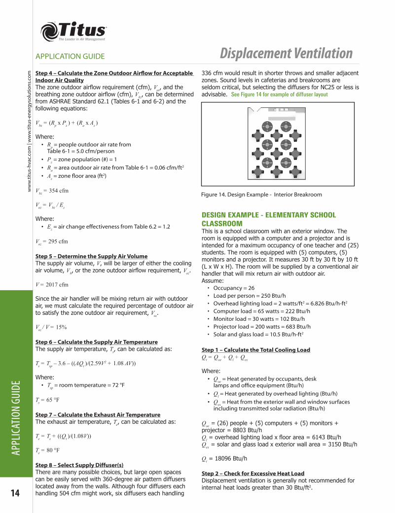
Step 8 – Select Supply Diffuser(s)There are many possible choices, but large open spaces can be easily served with 360-degree air pattern diffusers located away from the walls. Although four diffusers each handling 504 cfm might work, six diffusers each handling
336 cfm would result in shorter throws and smaller adjacent zones. Sound levels in cafeterias and breakrooms are seldom critical, but selecting the diffusers for NC25 or less is advisable. See Figure 14 for example of diffuser layout
DESIGN EXAMPLE - ELEMENTARY SCHOOL CLASSROOMThis is a school classroom with an exterior window. The room is equipped with a computer and a projector and is intended for a maximum occupancy of one teacher and (25) students. The room is equipped with (5) computers, (5) monitors and a projector. It measures 30 ft by 30 ft by 10 ft (L x W x H). The room will be supplied by a conventional air handler that will mix return air with outdoor air. Assume:• Occupancy = 26• Load per person = 250 Btu/h • Overhead lighting load = 2 watts/ft2 = 6.826 Btu/h-ft2
• Computer load = 65 watts = 222 Btu/h • Monitor load = 30 watts = 102 Btu/h• Projector load = 200 watts = 683 Btu/h• Solar and glass load = 10.5 Btu/h-ft2
Step 1 – Calculate the Total Cooling LoadQt = Qoe + Ql + Qex
Where:• Qoe = Heat generated by occupants, desk lampsandofficeequipment(Btu/h)
• Ql = Heat generated by overhead lighting (Btu/h)• Qex = Heat from the exterior wall and window surfaces
including transmitted solar radiation (Btu/h)
Qoe = (26) people + (5) computers + (5) monitors + projector = 8803 Btu/hQl = overhead lighting load x floor area = 6143 Btu/hQex = solar and glass load x exterior wall area = 3150 Btu/h
Qt = 18096 Btu/h
Step 2 – Check for Excessive Heat LoadDisplacement ventilation is generally not recommended for internal heat loads greater than 30 Btu/ft2.
Figure 14. Design Example - Interior Breakroom
Displacement Ventilation
ww
w.titu
s-hvac.com
| ww
w.titu
s-energ
ysolu
tion
s.com
15
APPLICATION GUIDE
APPLICATION GUIDE
Qt / A ≤ 30 Btu/ft2
A = L x W
Where:• A=floorarea(ft2)• L = room length (ft)• W = room width (ft)
Qt / A = 20.1 Btu/ft2
Step 3 – Calculate the Cooling Air VolumeThe cooling air volume, Vh, can be determined from heat loads with weighting factors applied:
Vh = 0.076Qoe + 0.034Ql + 0.048Qex
Vh = 1029 cfm
Step 4 – Calculate the Zone Outdoor Airflow for Acceptable Indoor Air QualityThe zone outdoor airflow requirement (cfm), Voz, and the breathing zone outdoor airflow (cfm), Vbz, can be determined from ASHRAE Standard 62.1 (Tables 6-1 and 6-2) and the following equations:
Vbz = (Rp x Pz ) + (Ra x Az )
Where:• Rp = people outdoor air rate from
Table 6-1 = 5.0 cfm/person• Pz = zone population (#) = 1• Ra = area outdoor air rate from Table 6-1 = 0.06 cfm/ft2
• Az=zonefloorarea(ft2)
Vbz = 368 cfm
Voz = Vbz / Ez
Where:• Ez = air change effectiveness from Table 6-2 = 1.2
Voz = 307 cfm
Step 5 – Determine the Supply Air VolumeThe supply air volume, V, will be larger of either the cooling air volume, Vh, or the zone outdoor airflow requirement, Voz.
V = 1029 cfm
Since the air handler will be mixing return air with outdoor air, we must calculate the required percentage of outdoor air to satisfy the zone outdoor air requirement, Voz.
Voz / V = 30%
Step 6 – Calculate the Supply Air TemperatureThe supply air temperature, Ts, can be calculated as:
Ts = Tsp – 3.6 – ((AQt )/(2.59V2 + 1.08 AV))
Where:• Tsp = room temperature = 74 °F
Ts = 66 °F
Step 7 – Calculate the Exhaust Air TemperatureThe exhaust air temperature, Te, can be calculated as:
Te = Ts + ((Qt )/(1.08V))
Te = 82 °F
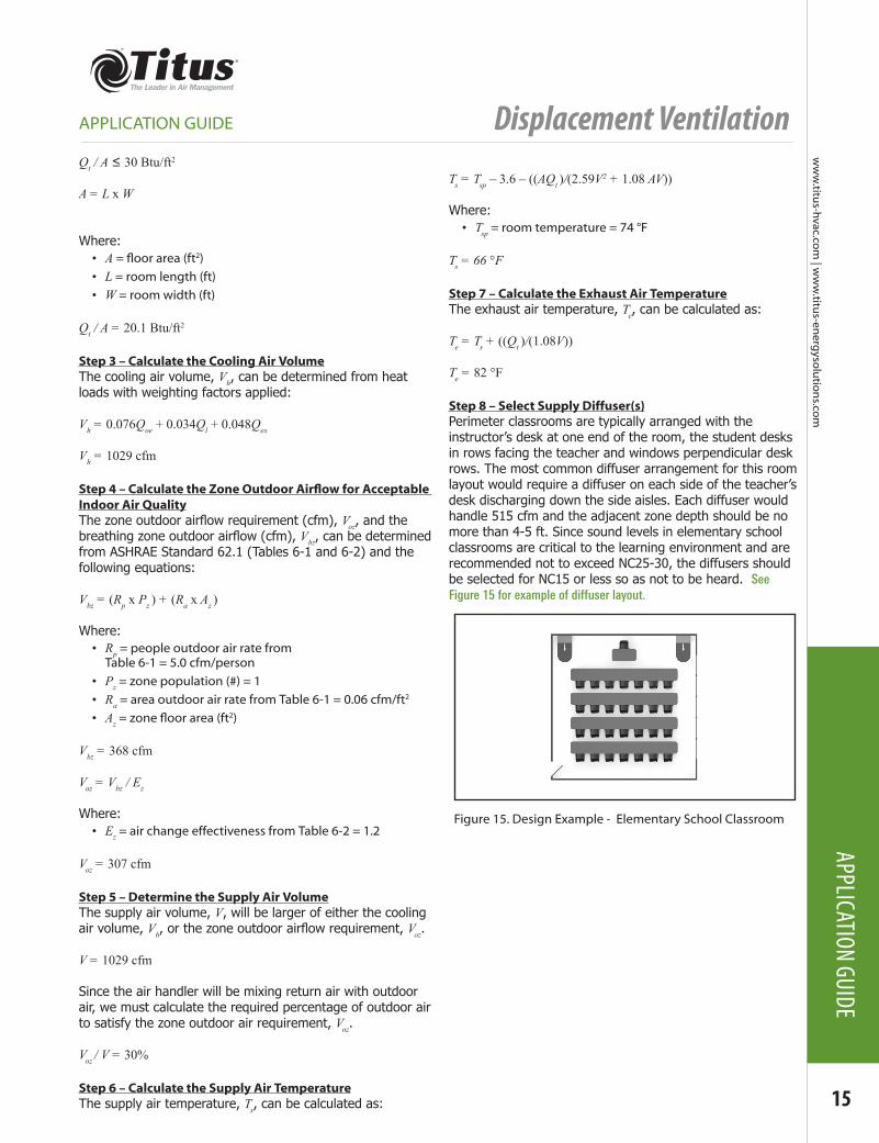
Step 8 – Select Supply Diffuser(s)Perimeter classrooms are typically arranged with the instructor’s desk at one end of the room, the student desks in rows facing the teacher and windows perpendicular desk rows. The most common diffuser arrangement for this room layout would require a diffuser on each side of the teacher’s desk discharging down the side aisles. Each diffuser would handle 515 cfm and the adjacent zone depth should be no more than 4-5 ft. Since sound levels in elementary school classrooms are critical to the learning environment and are recommended not to exceed NC25-30, the diffusers should be selected for NC15 or less so as not to be heard. See Figure 15 for example of diffuser layout.
Figure 15. Design Example - Elementary School Classroom
Displacement Ventilation
16
ww
w.ti
tus-
hvac
.co
m |
ww
w.ti
tus-
ener
gys
olu
tio
ns.
com
APPL
ICAT
ION
GUID
E
references
APPLICATION GUIDE
ASHRAE. 2011. 2011 ASHRAE Handbook-Applications, Chapter 57. Atlanta: American Society of Heating, Refrigerating and Air-Conditioning Engineers, Inc.
ASHRAE. 2010. ANSI/ASHRAE Standard 62.1-2010, Ventilation for Acceptable Indoor Air Quality. Atlanta: American Society of Heating, Refrigerating and Air-Conditioning Engineers, Inc.
ASHRAE. 2010. ANSI/ASHRAE Standard 55-2010, Thermal Environmental Conditions for Human Occupancy. Atlanta: American Society of Heating, Refrigerating and Air-Conditioning Engineers, Inc.
ASHRAE. 2009. ANSI/ASHRAE Standard 113-2009, Method of Testing for Room Air Diffusion. Atlanta: American Society of Heating, Refrigerating and Air-Conditioning Engineers, Inc.
ASHRAE. 2009. 2009 ASHRAE Handbook-Fundamentals, Chapter 20. Atlanta: American Society of Heating, Refrigerating and Air-Conditioning Engineers, Inc.
AHRI. 2008. AHRI Standard 885-2008, Procedure for Estimating Occupied Space Sound Levels in the Application of Air Terminals and Air Outlets. Arlington, VA: Air-Conditioning, Heating, and Refrigeration Institute, Inc.
Chen, Q., and L.R. Glicksman. 2003. System Performance Evaluation and Design Guidelines for Displacement Ventilation. Atlanta: American Society of Heating, Refrigerating and Air-Conditioning Engineers, Inc.
REHVA. 2002. Displacement Ventilation in Non-Industrial Premises, ed. Skistad, H. et al.
Displacement Ventilation
ww
w.titu
s-hvac.com
| ww
w.titu
s-energ
ysolu
tion
s.com
17
NOTES
NOTES
Displacement Ventilation
18
ww
w.ti
tus-
hvac
.co
m |
ww
w.ti
tus-
ener
gys
olu
tio
ns.
com
NOTE
S
NOTES

Displacement Ventilation
ww
w.titu
s-hvac.com
| ww
w.titu
s-energ
ysolu
tion
s.com
19
NOTES
NOTES

clever. creative. comfort.
605 Shiloh RoadPlano TX 75074
office: 972.212.4800fax: 972.212.4877
email: [email protected]