displacer level switch lectric level switch -t roducts · pdf file ·...
TRANSCRIPT

MS8DDisplacer Level Switch
Operating instruction manual OI/MS8D-EN Rev. B
Electric Level SwitchK-TEK Products
IntroductionThis operating instruction manual provides the following information: – Ordering information - see page 3 – Installation instructions - see page 4 – Wiring schematic - see page 5 – Reed switch protection - see page 5 – Maintenance - see page 6

2 MS8D Buoyancy Level Switch | Operating instruction manual
TABLE OF CONTENTS
1.0 Specifications ....................................................................................................................................................32.0 Ordering Information..........................................................................................................................................33.0 Description.........................................................................................................................................................34.0 Installation .........................................................................................................................................................45.0 Wiring Schematic...............................................................................................................................................56.0 Reed Switch Protection .....................................................................................................................................57.0 Maintenance ......................................................................................................................................................68.0 Handling and Storage ........................................................................................................................................69.0 Replacement Parts ............................................................................................................................................610.0 Warranty ...........................................................................................................................................................7
Operating instruction manual | MS8D Buoyancy Level Switch 3
1.0 Specifications
Switch Type: Magnetically actuated, hermetically sealed bistable switch, SPDT, Form CContact Material: Rhodium Alloy
Switch Action: Break before make
Maximum Deadband:AC Rating: 250 VAC, 1 Amp, 250 VA, resistiveDC Rating: 250 VDC, 1 Amp, 250 W, resistive (if higher contact ratings required see IR10 & PP10 Data Sheets)
Process Temperature: -40 to 302°F / -40 to 150°C
Maximum Pressure: 600 psig @ 300°F / 41 bar @ 150°C
Connections: 1” MNPT Process, 1/2” FNPT Conduit AWG 20 Wiring Harness (18 inch);MS8F Housing is 1-3/4” Hex for tightening into process connection.
Insertion Length: 10 in. / 254mm Standard; Optional lengths to 24 in. / 610 mm available
Materials: 316 Stainless Steel Wetted Parts
Specific Gravity: 0.4 Minimum (Clean Fluids)
Approvals: Factory Mutual (Pending)CSA (Pending)ATEX (Pending)
2.0 Ordering Information/ Dimensions (Refer to product Data Sheet MS8F-0202-1 for ordering information)
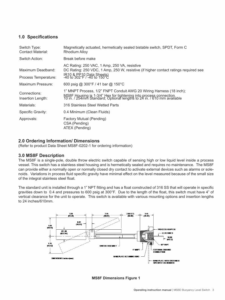
3.0 MS8F DescriptionThe MS8F is a single-pole, double throw electric switch capable of sensing high or low liquid level inside a process vessel. This switch has a stainless steel housing and is hermetically sealed and requires no maintenance. The MS8F can provide either a normally open or normally closed dry contact to activate external devices such as alarms or sole-noids. Variations in process fluid specific gravity have minimal effect on the level measured because of the small size of the integral stainless steel float.
The standard unit is installed through a 1” NPT fitting and has a float constructed of 316 SS that will operate in specific gravities down to 0.4 and pressures to 600 psig at 300°F. Due to the length of the float, this switch must have 4” of vertical clearance for the unit to operate. This switch is available with various mounting options and insertion lengths to 24 inches/610mm.
MS8F Dimensions Figure 1
4 MS8D Buoyancy Level Switch | Operating instruction manual
4.0 Installation
The MS8F is mounted to the process vessel via the integral 1 inch MNPT fitting. Suitable reducers and/or adapters may be used provided they do not interfere with the full stroke of the float. The MS8F should be tightened such that the external ground connection is at its lower most position.
The following procedure outlines the steps necessary to install the switch. WARNING! MAKE SURE CIRCUIT IS DE-ENERGIZED WHEN INSTALLING THE SWITCH.1. Inspect the switch for any signs of damage incurred during shipment. Mount the switch in a process connection at
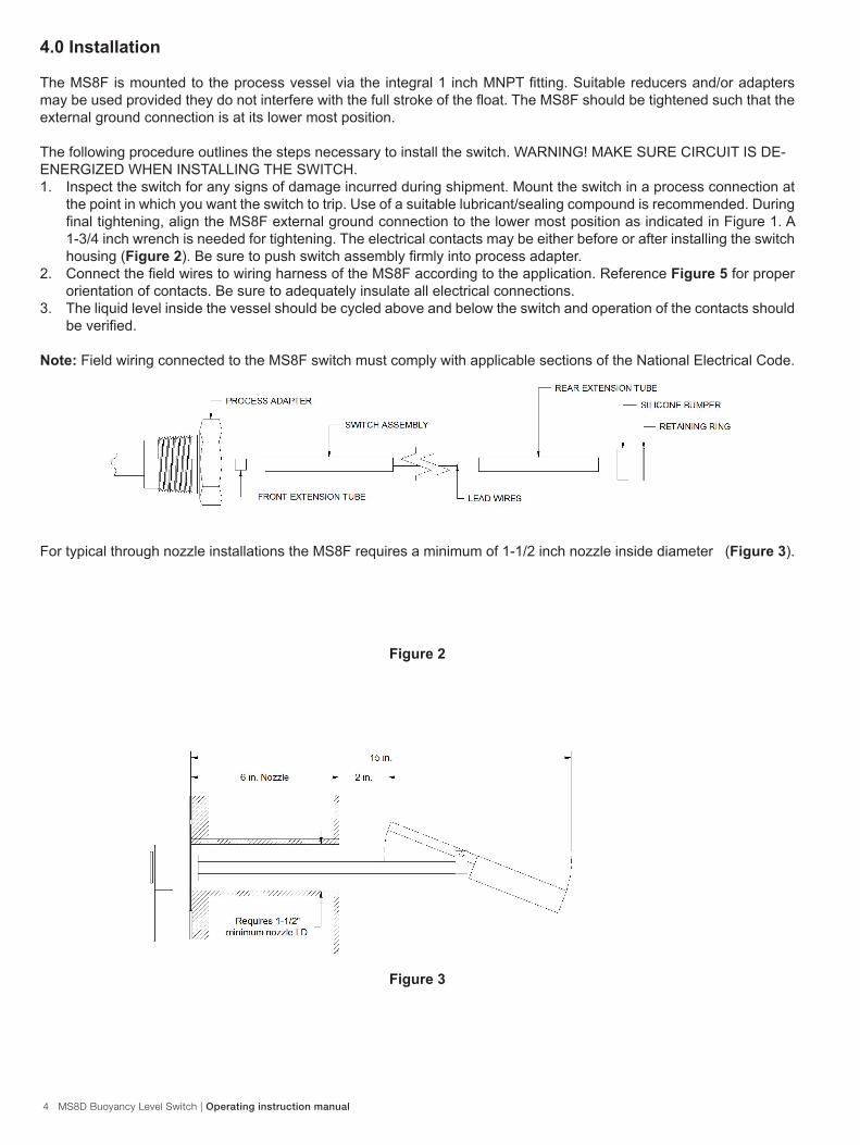
the point in which you want the switch to trip. Use of a suitable lubricant/sealing compound is recommended. During final tightening, align the MS8F external ground connection to the lower most position as indicated in Figure 1. A 1-3/4 inch wrench is needed for tightening. The electrical contacts may be either before or after installing the switch housing (Figure 2). Be sure to push switch assembly firmly into process adapter.
2. Connect the field wires to wiring harness of the MS8F according to the application. Reference Figure 5 for proper orientation of contacts. Be sure to adequately insulate all electrical connections.
3. The liquid level inside the vessel should be cycled above and below the switch and operation of the contacts should be verified.
Note: Field wiring connected to the MS8F switch must comply with applicable sections of the National Electrical Code.
For typical through nozzle installations the MS8F requires a minimum of 1-1/2 inch nozzle inside diameter (Figure 3).
Figure 2
Figure 3

Operating instruction manual | MS8D Buoyancy Level Switch 5
For inside nozzle installation the MS8F requires a minimum of 4 inches nozzle inside diameter. (Figure 4).
5.0 Wiring Schematic 6.0 Reed Switch Protection
Many of ABBs switch products (MS8F, MS8D, MS10, MS30, and MS50) are based on magnetically operated reed switches. Since reed switches have the inherent characteristics of very closely spaced switch contacts, it is extremely important to protect these contacts from high voltage transients caused by inductive loads. When an inductive load is de-energized, the collapsing magnetic field induces a high voltage of opposite polarity into itself and thus the switch. Two basic methods exist to clamp this voltage and thus protect the switch contacts.
6.1 DC Applications
For DC applications (Figure 6), a diode is placed in parallel with the inductive load (note the polarity of the diode and power supply). A 1N4001 general-purpose diode is normally sufficient to clamp the induced voltage of the inductive load to a safe level.
Figure 4
Figure 5

6 MS8D Buoyancy Level Switch | Operating instruction manual
Figure 6
6.2 AC Applications For AC applications (Figure 7), Metal Oxide Varistor (MOV transient surge suppressor) is placed parallel with the inductive load. The MOV changes from a high impedance when the voltage across the MOV exceeds its rated voltage (the MOV rating must correspond with the supply voltage). For 120 VAC control systems a typical MOV would be the GE (General Electric Co.) part number V130LA10A. The result is the limiting of the switch voltage to approximately 130 volts.
Note: For higher contact rating (> 1 amp) the following two accessory options are available:
PP10 Pumpak Controller; Two Switches Required; Includes EX and TB OptionIR10 Interposing Relay; One Per Switch; Includes EX and TB Option
7.0 MaintenanceThe MS8F does not require any routine maintenance in normal day to day operation.
WARNING! If there is a need to take the switch out of service or disconnect it for any reason, then make sure the circuit is de-energized, or insure that the area is known to be non-hazardous!
8.0 Handling and Storage RequirementsThere are no special handling and storage requirements associated with this device.
9.0 Replacement PartsField replaceable switch cartridge assembly (retaining ring, spacer tubes, and silicone bumper Figure 2) is available upon request.
Part Number: MS8F-Switch (MS8F Switch Cartridge Assembly)
Figure 7

Operating instruction manual | MS8D Buoyancy Level Switch 7
10.0 Warranty Statement5 YEAR WARRANTY FOR:KM26 Magnetic Liquid Level Gauges; MagWave Dual Chamber System; LS Series Mechanical Level Switches (LS500, LS550, LS600, LS700, LS800 & LS900) (does NOT include switching mechanisms, ie. MS30, MS40, MS41, PS35 & PS45); EC External Chambers, STW Stilling Wells and ST95 Seal Pots.
3 YEAR WARRANTY FOR:KCAP300 & KCAP400 capacitance switches.
2 YEAR WARRANTY FOR:AT100, AT100S and AT200 series transmitters; RS80 and RS85 liquid vibrating fork switches; RLT100 and RLT200 reed switch lev-el transmitters; TX, TS, TQ, IX and IM thermal dispersion switches; IR10 and PP10 External Relays; MT2000, MT5000, MT5100 and MT5200 radar level transmitters; RI100 Repeat Indicators; KP paddle switches; A02, A75 & A77 RF capacitance level switches and A38 RF capacitance level transmitters; Buoyancy Level Switches (MS50, MS10, MS8D & MS8F); Magnetic Level Switches (MS30, MS40, MS41, PS35 & PS45).
1 YEAR WARRANTY FOR:KM50 gauging device; AT500 and AT600 series transmitters; LaserMeter and SureShot series laser transmitters; LPM200 digital indicator; DPM100 digital indicators; APM100 analog indicators; KVIEW series digital indicators and controllers; GRANUPOINT and SLUDGEPOINT vibrating fork switches, SOLITRAK Electro-Mechanical Continuous Measuring Devices, KSONIK ultrasonic level switches, transmitters & transducers, ChuteMaster Microwave Transmitter / Receiver and TiltMaster Switches.
SPECIAL WARRANTY CONSIDERATIONS:ABB does not honor OEM warranties for items not manufactured by ABB (i.e. Palm Pilots). These claims should be handled di-rectly with the OEM.
ABB will repair or replace, at ABB’s election, defective items which are returned to ABB by the original purchaser within the period specified above from the shipment date of the item and which is found, upon examination by ABB, to its satisfaction, to contain defects in materials or workmanship which arose only under normal use and service and which were not the result of either al-terations, misuse, abuse, improper or inadequate adjustments, applications or servicing of the product. ABB’s warranty does not cover the repair or replacement of units that fail from the effects of excessive vibration unless the units are originally designed for vibration application. In addition, ABB’s warranty does not include on-site repair or services. Field service rates can be supplied on request.
If a product is believed to be defective, the original purchaser shall notify ABB and request a Returned Material Authorization before returning the material to ABB, with transportation prepaid by the purchaser. (To expedite all returns/repairs from outside of the United States, consult ABB’s customer service team ([email protected]) to determine an optimal solution for shipping method and turnaround time.) The product, with repaired or replaced parts, shall be returned to the purchaser at any point in the world with transportation prepaid by ABB for best-way transportation only. ABB is not responsible for expedited shipping charges. If the product is shipped to ABB freight collect, then it will be returned to the customer freight collect.
If inspection by ABB does not disclose any defects in material or workmanship, ABB’s normal charges for repair and shipment shall apply (minimum 250.00 USD).
The materials of construction for all ABB products are clearly specified and it is the responsibility of the purchaser to determine the compatibility of the materials for the application.

OI/
MS
8D-E
N R
ev.
B
06
.201
2
Contact us
NoteWe reserve the right to make technical changes or modify the contents of this document without prior notice. With regard to purchase orders, the agreedparticulars shall prevail. ABB does not accept any responsibility whatsoever for potential errors or possible lack of information in this document.
We reserve all rights in this document and in the subject matter and illustrations contained therein. Any reproduction, disclosure to third parties or utilization of its contents - in whole or in parts – is forbidden without prior written consent of ABB.
Copyright© 2012 ABBAll rights reserved
ABB Inc. 18321 Swamp RoadPrairieville, LA 70769 USAPhone: +1 225 673 6100Service: +1 225 677 5836Fax: +1 225 673 2525Service e-mail: [email protected]
www.abb.com/level