display pic 16f877a nurulafiza bt ramli this...
TRANSCRIPT
AN ELECTRONIC CLOCK DISPLAY USING OMRON PLC TRAINER AND
PIC 16F877A
NURULAFIZA BT RAMLI
This report is submitted in partial fulfillment of the requirements for the award
of Bachelor of Electronic Engineering (Computer Engineering) With Honours
Faculty of Electronic and Computer Engineering
Universiti Teknikal Malaysia Melaka
April 2009
UNIVERSTI TEKNIKAL MALAYSIA MELAKA FAKULTI KEJURUTERAAN ELEKTRONIK DAN KEJURUTERAAN KOMPUTER
BORANG PENGESAHAN STATUS LAPORAh' PROJEK SARJANA MUDA I1
AN ELECTRONIC CLOCK DISPLAY USING OMRON
I1 TajukProjek : PLCTRAINERANDPIC 16F877A
Sesi : .............. .2008/2009.. ........................................... Pengajian
Saya ......................... NURULAFIZA BT RAMLI.. ................................................. (HURUF BESAR)
mengaku membenarkan Laporan Projek Sarjana Muda ini dishpan di Perpustakaan dengan syarat-syarat kegunaan seperti berikut:
1 . Laporan adalah hakrnilik Universiti Teknikal Malaysia Melaka.
2. Perpustakaan dibenarkan membuat salinan untuk tujuan pengajian sahaja.
3. Perpustakaan dibenarkan membuat salinan laporan ini sebagai bahan pertukaran antara institusi
pengajian tinggi.
4. Sila tandakan ( d ) :
SULIT*
TERHAD*
,
TIDAK TERHAD
(Mengandungi maklumat yang berdarjah keselamatan atau kepentingan Malaysia seperti yang termaktub di dalam AKTA RAHSIA RASMI 1972)
(Mengandungi maklumat terhad yang telah ditentukan oleh organisasiroadan di mana penyelidikan dijalankan)
Disahkan oleh:
Alarnat Tetap: Lot 36 Kg. Sg. Deraka, Jalan Tanjung Lumpur, 25 150 Kuantan Pahang Darul Makmur
* (COP DAN TANDATANGAN PENYELIA)
FARlD ARAFAT BIN AZlDlN Pensyarah
Fskutti Kejuruteraan Elektronik Dan Kejuruteraan Kornpute~ Universiti Teknikal Malaysta Melaka (UTeLl)
Karung Berkunci No 1752 Pejabat Pos Durian Tunggal
76105 Durian Tunggal. Melaka
I Tarikh: ..... .30 April 2009.. ............ Tarikh: ..... .30 April 2009.. ..........

"I hereby declare that this report is the result of my own work except for quotes as
cited in the reference"
Signature : .......... Author
Date : 30 APRIL 2009
"I hereby declare that I have read this report and in my opinion this report is
sufficient in terms scope and quality for the award of Bachelor of Electronic
Engineering (Computer Engineering) With Honours"
QbP-P Signature : . . . . . . . . . . . . . . . . c.. . Name : MR FARID ARAFAT BIN AZIDIN
Date : 30 APRIL 2009

Special dedication to my beloved father and mom, my entire sibling and my kind
hearted supervisor Mr. Farid Arafat bin Azidin, and my dearest friends.
ACKNOWLEDGEMENTS
I would like to extend my sincere gratitude to my supervisor, Mr. Farid
Arafat bin Azidin, for her assistance and guidance toward the progress of this thesis
project. Through the year, Mr. Farid Arafat bin Azidin has been patiently monitoring
my progress and guided me in the right direction and offering encouragement.
Obviously the progress I had now will be uncertain without his assistance. My
special appreciation and thank to my friend Mohd Firdaus and Noor Roha for their
invaluable assistances towards this thesis project. I also would like to thank to my
family especially to my parents without their support and understanding this would
not have been possible.
ABSTRACT
The project aim was to a built an electronic board which detect signal from
Omron PLC trainer. A programmable logic controller (PLC) in an operating system
such as a machine includes a software development. The hardware part was based on
a simple circuit on Printed Circuit Board (PCB) with LCD display. The signals from
programmable logic circuit were transferred to PCB board as a time clock signal.
PIC 16F877A microcontroller was used as interface in order to display time clock on
LCD display. The electronic board also was designed with the voltage regulator to
step down the voltage, 24V form PLC to 5V. The software development started with
the flow chart, ladder diagram for PLC and finally, the software was written in C
language and implement on the PIC. As the result, whenever the PLC counting and
change the signal (clock), the LCD display will shown the output simultaneously
with the PLC.
ABSTRAK
Tujuan utama projek ini adalah membina satu litar elektronik yang marnpu
mengesan signal yang dihasilkan oleh Omron PLC. Litar eleckronik ini terdiri
daripada litar PCB dan paparan LCD Isyarat yang di hasilkan dari PCB board akan
dihantar ke litar untuk menghasilkan keluaran masa di paparan LCD. PIC16F877A
akan digunakan untuk menjana keluaran isyarat masa di paparan LCD. Litar
elektronik ini juga akan dilengkapi dengan litar voltage regulator untuk merendahkan
nilai voltage dr 24V kepada 5V. Pembangunan perisian akan dimulakan dengan
membina carta alir, gambarajah ladder dan di aplikasikan ke dalam PIC dalam
bentuk kod. Sebagai keputusannya, apabila terdapat perubahan isyarat dari PLC
maka isyarat yg diterima serta di hantar kepada paparan LCD secara serentak.
CHAPTER TITLE
PROJECT TITLE
DECLARATION 1
DECLARATION 2
DEDICATION
ACKNOWLEDGEMENT
ABSTRACT
ABSTRAK
TABLE OF CONTENT
LIST OF TABLES
LIST OF FIGURES
LIST OF SYMBOLS
LIST OF APPENDIX
I INTRODUCTION
1.1 Project Introduction
1.2 Objective Project
1.3 Problem Statement
1.4 Scope of Project
1.5 Methodology
1.6 Thesis Outline
PAGES
. . 11
. . . 111
iv
v
vi
vii . . .
Vlll
ix
xii
xiii
xv
xvi
I1 LITERATURE REVIEW
2.1 Definition PLC
2.1.1 Features of PLC
2.1.2 Ladder Logic
2.1.3 Discrete Input and Output System
2.2 Microcontroller
2.2.1 Identifying suitable Microcontroller
2.2.2 PIC 16F877A
2.2.3 Pin Description
2.2.4 Introduction to CCS C Compiler
2.2.5 Introduction to Proteus VSM 6.9
2.2.6 LCD Display
I11 METHODOLOGY
3.1 Flow chart
3.2 Project Planning
3 -2.1 Planning
3.2.2 Work Flow
3.3 Software Development
3.3.1 Introduction to CX-Programmer
3.3.2 Setting for Program
3 -3.3 Ladder Diagram Languages
3.3.4 System for the Content
3.3.5 Transfer to PLC
3.3.6 PLC Work Online Simulator
3.4 Hardware Development
3.4.1 Voltage Regulator
3.4.2 PIC 16F877A and LCD Display
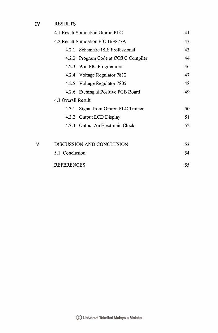
IV RESULTS
4.1 Result Simulation Ornron PLC
4.2 Result Simulation PIC 16F877A
4.2.1 Schematic ISIS Professional
4.2.2 Program Code at CCS C Compiler
4.2.3 Win PIC Programmer
4.2.4 Voltage Regulator 7812
4.2.5 Voltage Regulator 7805
4.2.6 Etching at Positive PCB Board
4.3 Overall Result
4.3.1 Signal from Ornron PLC Trainer
4.3.2 Output LCD Display
4.3.3 Output An Electronic Clock
V DISCUSSION AND CONCLUSION
5.1 Conclusion
REFERENCES

xii
TABLE LIST
TABLE TITLE
2.1 PIC 16F877A 110 Pin Discretions
4.1 Output of PLC
4.2 Counter of PLC
4.3 Timer of PLC
PAGES
LIST OF FIGURES
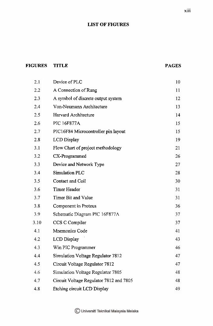
FIGURES TITLE
... Xl l l
PAGES
Device of PLC
A Connection of Rung
A symbol of discrete output system
Von-Neumann Architecture
Harvard Architecture
PIC 16F877A
PIC 16F84 Microcontroller pin layout
LCD Display
Flow Chart of project methodology
CX-Programmed
Device and Network Type
Simulation PLC
Contact and Coil
Timer Header
Timer Bit and Value
Component in Proteus
Schematic Diagram PIC 16F877A
CCS C Compiler
Mnemonics Code
LCD Display
Win PIC Programmer
Simulation Voltage Regulator 78 12
Circuit Voltage Regulator 78 12
Simulation Voltage Regulator 7805
Circuit Voltage Regulator 7812 and 7805
Etching circuit LCD Display
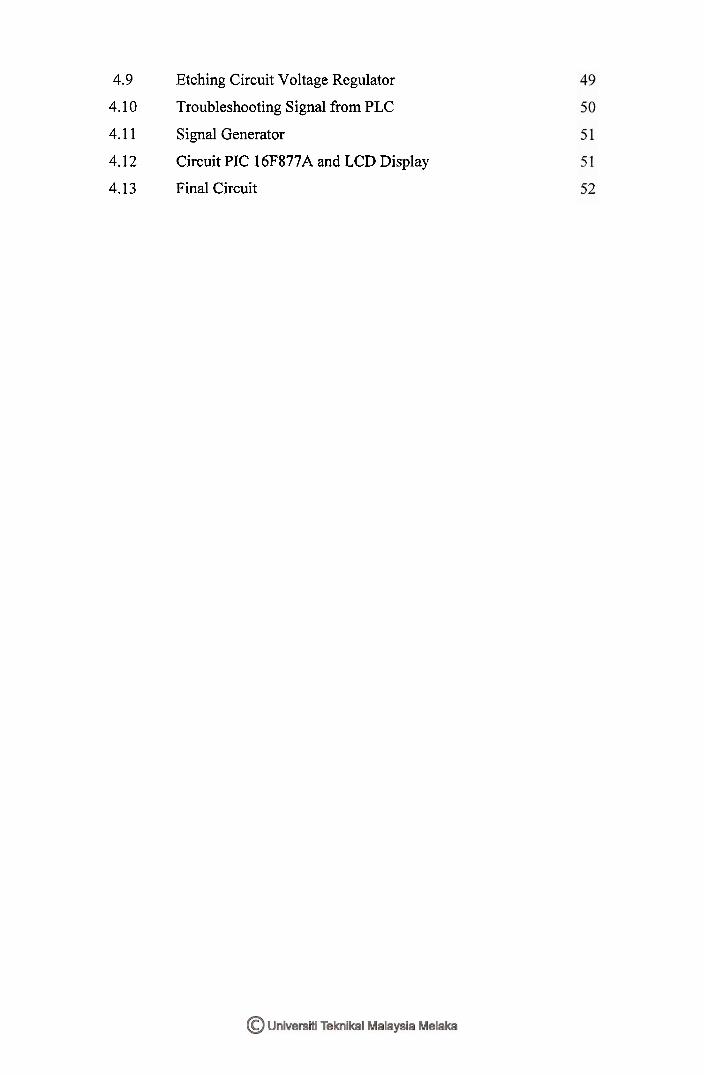
4.9 Etching Circuit Voltage Regulator
4.10 Troubleshooting Signal from PLC
4.1 1 Signal Generator
4.12 Circuit PIC 16F877A and LCD Display
4.13 Final Circuit
LIST OF SYMBOLS
PLC - Programmable Logic Controller
PIC - Peripheral Interface Circuit
I/O - Input and Output
LCD - Liquid Crystal Display

LIST OF APPENDIX
NO TITLE
A LADDER DIAGRAM FOR CX-PROGRAMMER
B DATASHEET PIC 16F877A
PAGES
CHAPTER I
INTRODUCTION
1.1 Project Introduction
Programmable logic controllers (PLC) have gained a very strong position in the
industrial automation field. The growing complexity of the applications of PLC strongly
depends on programmers and maintenance personnel. Hence, PLC education is a great
demand nowadays. Programmable logic controllers (PLC) were originally design to
control processes that required a sequence of events to be follow. Today, PLCs have
advanced to the stage of being incorporate in SCADA (Supervisory Control and Data
Acquisition) systems, continuous control systems. In industry, there are several
manufacturers of PLCs, most of the instruction formats of PLC may not the same for
different brands, but the hardware structures and programming concepts are very similar.
For this project, the PLC was used to generate time clock and monitor the functional of
electronic device. The signal from the PLC will be integrated at an electronic board,
which is containing voltage regulator, LCD display and PIC 16F877A. In order to
display the clock, PIC 16F877A was used to receive and analyze signal from PLC. This
system provides a user friendly graphical interface and allowing analysis of PLC
program and implemented in the real time simulation.
1.2 Objective of Project
The main objective of this project is to design an electronic board with the
capability to detect the signal from PLC and generate output time clock at LCD display
by using PIC 16F877A within the required timeline and also to develop programming
code based on PIC based system to support application of LCD display.
1.3 Problem Statement
In the virtual PLC, the program is written using the Relay Ladder Language and
supported by the programming editor. In run mode, the PLC makes its simulation of the
ladder program based on its input and the program and displays the output. However, the
output that has been generated was not easy to identify since the PLC just give the
output by shown it based on the lightning of button output. In order to apply the
application on PLC, it is needed to make sure PLC can be a user friendly system so that
user can analyze the output easily. Therefore, for this project, as we know PLC can
generate time clock however, it did not provide any display system for the user. Hence,
it is necessary to integrate the PLC with other display system that is LCD display. In
order to display using LCD display it is use PIC 16F877A as it interface to receive the
signal from the PLC. In addition, the communication between PLC and PIC is a new
innovation part in the industry since, people can see the growth in the technology if the
two different technology was combined. Hence the complexity of the design can be
develop and improve the features of the technology.

1.4 Scope of Project
I. Literature study on the PLC program to identify how to use CX-program and
develop ladder languages foe generate time clock.
11. Study the signal generated from PLC based on Ladder Programming.
111. Literature study on the Proteus VSM 6.0 to know how to use PIC 16F877A.
IV. Study on Proteus VSM 6.0 to understand the application of PIC to display
output by using LCD display.
V. Develop and analyze the program efficiently in C programming language and
by using ISIS 6 professional.
VI. Design, and built an electronic board which can detect signal form Omron
PLC trainer and can display the output at LCD display by using PIC
16F877A.
VII. Integrate between the hardware and software after all design completed.
1.5 Methodology
Phase1:-
Identify the problem statement, which is how to generate time clock by using
Omron PLC trainer and how to display the clock at LCD display by using PIC16F877A.
Phase2:-
Make a literature review for the project system including study about the
component that will be use, their characteristic and understand deeply about the circuit
and how it operates and analyze the datasheet of component involved such as (PLC,
voltage divider, PIC and LCD display).
Phase3:-
For this phase, it called as software development, where involve analyze and
study to design a ladder diagram by using CX-program to generate time clock and
simulation PIC 16F877A by using Proteus VSM 6.9 to display the output at LCD
display.
Phase4:-
For this phase, it called as hardware design. There are two phase for hardware
design, which is Voltage regulator's circuit,PIC 16F877A and LCD's circuit. All
components must have extra features to make sure the troubleshooting circuit can be
done easily.
Phase5:-
For this final phase, it called performance test. In this phase, the software part
and hardware part need to be combining together to get the result and to achieve the
objective of project. The final results is then being compared with the theoretical. After
that, the circuit that already constructed will be tested its functional, ability & weakness.
If there is any error detected, the troubleshooting process will be done in order to make
sure the circuit is well functioning.
1.6 Thesis Outlines
This thesis consists of five chapters. The following chapters are the outline of the
implementation of an electronic board which can detect signal form PLC to generate
time clock and display the output at LCD display by using PIC 16F877A.
Chapter I Will discuss briefly the overview of this project such as introduction,
objectives, methodology and thesis outlines.
Chapter I1 Contains the research and information about the project on several
important concepts of ladder diagram on PLC, C-programming language on PIC
16F877A, technology and tools in the study. Every facts and information, which found
through journals or other references, will be compared and the better methods have been
chose for the project.
Chapter 111 Includes the detail about designing and programming to generate
time clock system by using PLC and to display the output at the LCD display.
Simulation results, analysis, observation and discussion of the performance to generate
time clock technique are presented in.
Chapter IV Includes the detail about the hardware design involved schematic
diagram, PCB layout, components required and working principle for each circuit
especially for circuit PIC 16F877A and LCD display.
Chapter V Describes more about the discussion, and project findings. The result
is then presented in figures or plotted graph. This chapter also discuss about the
conclusion of the project and the future recommendations.
CHAPTER I1
LITERATURE REVIEW
This chapter contains the research and information about the project on several
important concepts of ladder diagram on PLC, C-programming language on PIC
16F877A, technology and tools in the study. Every facts and information, which found
through journals or other references, has been compared and the better methods have
been choosing among them
2.1 Definition of PLC
A Programmable Logic Controller (PLC) also referred to as programmable
controller. It is the name given to a type of computer commonly used in commercial and
industrial control applications. PLC have been gaining popularity on the factory floor
because of the advantages they offer such as:
a) Cost effective for controlling Complex system.
b) Flexible and can be reapplied to control other system quickly and easily.
c) Computational abilities allow more sophisticated control.
d) Reliable components make these likely to operate for years before failure.
e) Troubleshooting aids make programming easier and reduce downtime.
PLC is different from office computers in the types of tasks that they perform
and the hardware and software they require performing these tasks. While the specific
applications changeable widely, all PLCs monitor inputs and other variable values and
make decisions based on a stored program, and control outputs.
The basic operation and elements of a PLC is including input models (points), a
central processing unit (CPU). Output models (points) and a programming device. For
the input models of PLC it is depends upon the types of input devices used. Some of the
input models respond to digital input (discrete inputs) and other input models respond to
analog signals. The primary function of a PLC circuitry is to convert the signal provided
by these various switches and sensor into logic signal that can be used by the CPU.
The CPU evaluates the input, output, and other variables and executes as a stored
program. The CPU sends signals to update the status of the output. Output modules will
convert control signal from the CPU into digital values that can be used to control a
various type output devices. While the programming device is used to change the PLC's
program, monitor and change stored values.
2.1.1 Features of PLC
The main difference from other computers is that PLC is armored for severe
condition such as dust, moisture, heat, cold and ext which have the facility for extensive
input/output (I/O) arrangements. These connect the PLC to sensors and actuators. PLCs
read limit switches, analog process variables such as temperature and pressure and the
positions of complex positioning systems. On the actuator side, PLCs operate electric
motors, pneumatic or hydraulic cylinders, magnetic relays or solenoids, or analog
outputs. The input/output arrangements may be built into a simple PLC or the PLC may
have external 110 modules attached to a computer network that plugs into the PLC.
PLCs were invented as replacements for automated systems that would use hundreds or