dispositivo de aterramento e curto circuito.pdf
TRANSCRIPT
8/9/2019 Dispositivo de aterramento e curto circuito.PDF
http://slidepdf.com/reader/full/dispositivo-de-aterramento-e-curto-circuitopdf 1/22
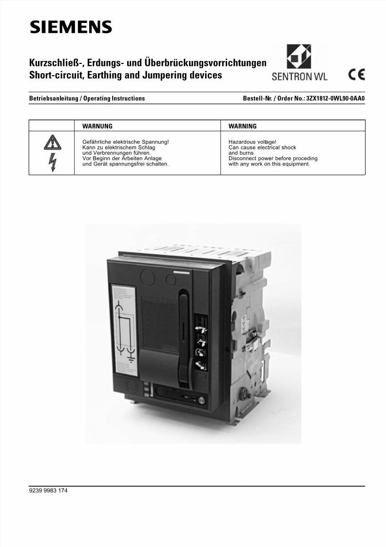
Kurzschließ-, Erdungs- und ÜberbrückungsvorrichtungenShort-circuit, Earthing and Jumpering devices
WARNUNG WARNING
Gefährliche elektrische Spannung!Kann zu elektrischem Schlagund Verbrennungen führen.Vor Beginn der Arbeiten Anlageund Gerät spannungsfrei schalten.
Hazardous voltage!Can cause electrical shockand burns.Disconnect power before procedingwith any work on this equipment.
9239 9983 174
Betriebsanleitung / Operating Instructions Bestell-Nr. / Order No.: 3ZX1812-0W
s
8/9/2019 Dispositivo de aterramento e curto circuito.PDF
http://slidepdf.com/reader/full/dispositivo-de-aterramento-e-curto-circuitopdf 2/22
Note
These instructions do not purport to cover all details or variations inequipment, nor to provide for every poss ible contingency to be metin connection with installation, operation or maintenance.
Should further information be desired or should particular problemsarise which are not covered sufficiently for the Purchaser’s purpo-ses, the matter should be referred to the local Siemens SalesOffice.
The contents of this instruction manual shall not became part ormodify any prior or existing agreement, commitment or relationship.The sales contract contains the entire obligations of Siemens. Thewarranty contained in the contract between the parties in the solewarranty of Siemens. Any statements contained herein do notcreate new warranties or modify the existing warranty.
SENTRON ® is a trade-mark of Siemens AG. The other designati-ons in this documentation can be trade-marks. Use by third partiesfor their own purposes violates the owner’s rights.
Symbols
Hinweis
Diese Betriebsanleitung enthält aus Gründen der Übersichtlichkeitnicht sämtliche Detailinformationen zu allen Typen des Produktsund kann auch nicht jeden denkbaren Fall der Aufstellung, desBetriebes oder der Instandhaltung berücksichtigen.
Sollten Sie weitere Informationen wünschen, oder sollten beson-dere Probleme auftreten, die in der Betriebsanleitung nicht ausführ-lich genug behandelt werden, können Sie die erforderlicheAuskunft über die örtliche Siemens-Niederlassung anfordern.
Außerdem weisen wir darauf hin, dass der Inhalt dieser Betriebsan-leitung nicht Teil einer früheren oder bestehenden Vereinbarung,Zusage oder eines Rechtsverhältnisses ist oder dieses abändernsoll. Sämtliche Verpflichtungen von Siemens ergeben sich aus dem
jeweiligen Kaufvertrag, der auch die vollständige und a lleingültigeGewährleistungsregelung enthält. Diese vertraglichen Gewährlei-stungsbestimmungen werden durch die Ausführung dieserBetriebsanleitung weder erweitert noch beschränkt.
SENTRON ® ist eine eingetragene Marke der Siemens AG. Dieübrigen Bezeichnungen in dieser Dokumentation können Markensein, deren Benutzung durch Dritte für deren Zwecke die Rechteder Inhaber verletzt.
Symbole
Warnhinweis Warning
CE-Zeichen CE identification
Kreuzschlitzschraubendreher Philips (PH), PoziDriv (PZ)
Cruciform screwdriver Philips (PH), PoziDriv (PZ)
Innensechskant-Schraubendreher Hexagon socket screwdriver
Anzugsdrehmoment Tightening torque
Handschriftlich ergänzen Add in writing
Erster Schritt einer Handlungsabfolge First step of action sequence
10 Nm
1

8/9/2019 Dispositivo de aterramento e curto circuito.PDF
http://slidepdf.com/reader/full/dispositivo-de-aterramento-e-curto-circuitopdf 3/22
1
Inhalt1 Lieferumfang 2
2 Bestimmung 4
3 Montage 5Konfigurieren 5
Konfiguration 1 5Konfiguration 2 7
Konfiguration 3 8Konfiguration 4 10Zusammenbau 10Abschließende Arbeiten 16
Querschnitt der Anschlussschienen anpassen 16Nennstromkodierung 17Klebeschild 17
4 Bedienung 17
5 Umrüsten 17Konfiguration ändern 17Zulässigen Bemessungsstrom ändern 18
6 Bestellnummern 18
Contents1 Scope of supply 2
2 Specifications 4
3 Assembly 5Configuring 5
Configuration 1 5Configuration 2 7
Configuration 3 8Configuration 4 10Assembly 10Final steps 16
Adjusting the cross-section of the connecting bars 16Rated current coding 17Labels 17
4 Operation 17
5 Conversion 17Changing configuration 17Changing the permissible rated current 18
6 Order numbers 18
8/9/2019 Dispositivo de aterramento e curto circuito.PDF
http://slidepdf.com/reader/full/dispositivo-de-aterramento-e-curto-circuitopdf 4/22
2
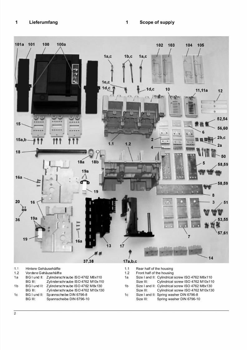
1 Lieferumfang
1.1 Hintere Gehäusehälfte1.2 Vordere Gehäusehälfte1a BG I und II: Zylinderschraube ISO 4762 M8x110
BG III: Zylinderschraube ISO 4762 M10x1101b BG I und II: Zylinderschraube ISO 4762 M8x130
BG III: Zylinderschraube ISO 4762 M10x1301c BG I und II: Spannscheibe DIN 6796-8
BG III: Spannscheibe DIN 6796-10
1 Scope of supply
1.1 Rear half of the housing1.2 Front half of the housing1a Size I and II: Cylindrical screw ISO 4762 M8x110
Size III: Cylindrical screw ISO 4762 M10x1101b Size I and II: Cylindrical screw ISO 4762 M8x130
Size III: Cylindrical screw ISO 4762 M10x1301c Size I and II: Spring washer DIN 6796-8
Size III: Spring washer DIN 6796-10

8/9/2019 Dispositivo de aterramento e curto circuito.PDF
http://slidepdf.com/reader/full/dispositivo-de-aterramento-e-curto-circuitopdf 5/22
3
1d Zylinderschraube DIN 912 M8x451e BG I und II: Zylinderschraube DIN 912 M8x30
BG III: Zylinderschraube DIN 912 M8x452 Anschlussschiene oben2a Einlegemutter M6x20x202b Zylinderschraube DIN 912 M6x302c Spannscheibe DIN 6796-63 Anschlussschiene unten4 Distanzstück
5 Längsbrücke6 Adapterplatte oben (nur BG I und II)7 Adapterplatte unten (nur BG I und II)8 Querbrücke10 Lichtbogenkammerdeckel11 BG I und II: Flachkopfschraube M6x40
BG III: Senkkopfschraube M6x4511a Spannscheibe DIN 6796-6 (nur BG I und II)12 Leiste (nur BG III)13 Montageplatte14 Blindblock15 Wandlerabdeckung15a Zylinderschraube DIN 912 M6x3015b Spannscheibe DIN 6796-6
16 Schalterfußsatz16a Senkkopfschraube DIN 7991 M6x2017 Einfahrantrieb17a Zylinderschraube DIN 6912 M6x1217b Spannscheibe DIN 6796-617c Scheibe DIN 9021-6,418 Einfahrwelle, komplett18a Kurbel, komplett18b Sicherungsring DIN 471-17x119 Erdungskontakt, komplett19a BG I und II: Senkkopfschraube ISO 7046 M5x12
BG III: Senkkopfschraube ISO 2009 M5x2020 Kodierstück36 Senkkopfschraube DIN 7500 M5x12
37 Zylinderschraube DIN 912 M6x1638 Scheibe DIN 9021-6,450 Zylinderschraube DIN 912 M6x45 Z9 (mit Spannscheibe)51 Zylinderschraube DIN 912 M6x30 Z9 (mit Spannscheibe)52 Zylinderschraube DIN 912 M6x25 Z9 (mit Spannscheibe)53 Zylinderschraube DIN 912 M6x25 Z9 (mit Spannscheibe)54 Zylinderschraube DIN 912 M6x40 (nur für BG II)55 Zylinderschraube DIN 912 M6x40 (nur für BG II)56 Sechskantmutter DIN 934 M657 Sechskantmutter DIN 934 M658 Zylinderschraube DIN 6912 M6x2059 Spannscheibe DIN 6796-660 Spannscheibe DIN 6796-661 Spannscheibe DIN 6796-6100 Bedienpult, komplett100a Schraube DIN 7964 M6x30101 Cover (Für BG I, 3-polig nicht erforderlich)101a BG I und II: Flachkopfschraube ISO 7045 M6x20
BG III: Flachkopfschraube ISO 7045 M6x12102 Abdeckfolie - Anschlüsse oben und unten kurzgeschlossen
und geerdet103 Abdeckfolie - Anschlüsse oben und unten überbrückt104 Abdeckfolie - Anschlüsse unten kurzgeschlossen und geer-
det105 Abdeckfolie - Anschlüsse oben kurzgeschlossen und geer-
det
1d Cylindrical screw DIN 912 M8x451e Size I and II: Cylindrical screw DIN 912 M8x30
Size III: Cylindrical screw DIN 912 M8x302 Upper connecting bar 2a Square nut M6x20x202b Cylindrical screw DIN 912 M8x302c Spring washer DIN 6796-63 Lower connecting bar 4 Spacer
5 Longitudinal bridge6 Upper adapter plate, (only size I and II)7 Lower adapter plate (only size I and II)8 Transverse bridge10 Arc chute cover 11 Size I and II: Pan-head screw M6x40
Size III: Countersunk screw M6x4511a Spring washer DIN 6796-6 (only size I and II)12 Strip (only size III)13 Mounting plate14 Dummy module15 Transformer cover 15a Cylindrical screw DIN 912 M6x3015b Spring washer DIN 6796-6
16 Circuit-breaker feet set16a Countersunk screw DIN 7991 M6x2017 Racking mechanism17a Cylindrical screw DIN 912 M6x1217b Spring washer DIN 6796-617c Washer DIN 9021-6,418 Racking shaft, complete18a Crank, complete18b Retaining ring DIN 471-17x119 Ground contact, complete19a Size I and II: Countersunk screw ISO 2009 M5x12
Size III: Countersunk screw ISO 2009 M5x2020 Coding element36 Countersunk screw DIN 7500 M5x12
37 Cylindrical screw DIN 912 M6x1638 Washer DIN 9021-6,450 Cylindrical screw DIN 912 M6x45 Z9 (with spring washer)51 Cylindrical screw DIN 912 M6x30 Z9 (with spring washer)52 Cylindrical screw DIN 912 M6x25 Z9 (with spring washer)53 Cylindrical screw DIN 912 M6x25 Z9 (with spring washer)54 Cylindrical screw DIN 912 M6x40 (only for size II)55 Cylindrical screw DIN 912 M6x40 (only for size II)56 Hexagon nut DIN 934 M657 Hexagon nut DIN 934 M658 Cylindrical screw DIN 912 M6x2059 Spring washer DIN 6796-660 Spring washer DIN 6796-661 Spring washer DIN 6796-6100 Front panel, complete100a Screw DIN 7964 M6x30101 Cover (not necessary for size I, 3-pole)101a Size I and II: Pan-head screw ISO 7045 M6x20
Size III: Pan-head screw ISO 7045 M6x12102 Cover foil - The upper and lower connections are short-cir-
cuited and earthed103 Cover foil - The upper and lower connections are jumped104 Cover foil - The lower connections are short-circuited and
earthed105 Cover foil - The upper connections are short-circuited and
earthed

8/9/2019 Dispositivo de aterramento e curto circuito.PDF
http://slidepdf.com/reader/full/dispositivo-de-aterramento-e-curto-circuitopdf 6/22
4
2 Bestimmung
Die Kurzschließ-, Erdungs- und Überbrückungsvorrichtung (nach-folgend kurz KSV genannt) kann an Stelle eines Einschub-Lei-stungsschalters vom Typ SENTRON WL für die Durchführungverschiedener Prüfungen in Niederspannungsschaltanlagen einge-setzt werden.
Dabei sind vier verschiedene Konfigurationen möglich.
Konfiguration 1
Obere Anschlüsse sind kurzgeschlossen und geerdet.
Konfiguration 2
Untere Anschlüsse sind kurzgeschlossen und geerdet.
Konfiguration 3Untere und obere Anschlüsse sind überbrückt, kurzgeschlossenund geerdet.
Konfiguration 4Untere und obere Anschlüsse sind überbrückt.
2 Specifications
The short-circuit, earthing and jumpering device (hereinafter refer-red to as SCD) can be used instead of a SENTRON WL type draw-out circuit-breaker for the performance of various tests on low-voltage switchgear.
Four different configurations are possible.
Configuration 1
The upper connections are short-circuited and earthed.
Configuration 2
The lower connections are short-circuited and earthed.
Configuration 3The upper and lower connections are jumped, short-circuited andearthed.
Configuration 4The upper and lower connections are jumped.
8/9/2019 Dispositivo de aterramento e curto circuito.PDF
http://slidepdf.com/reader/full/dispositivo-de-aterramento-e-curto-circuitopdf 7/22
5
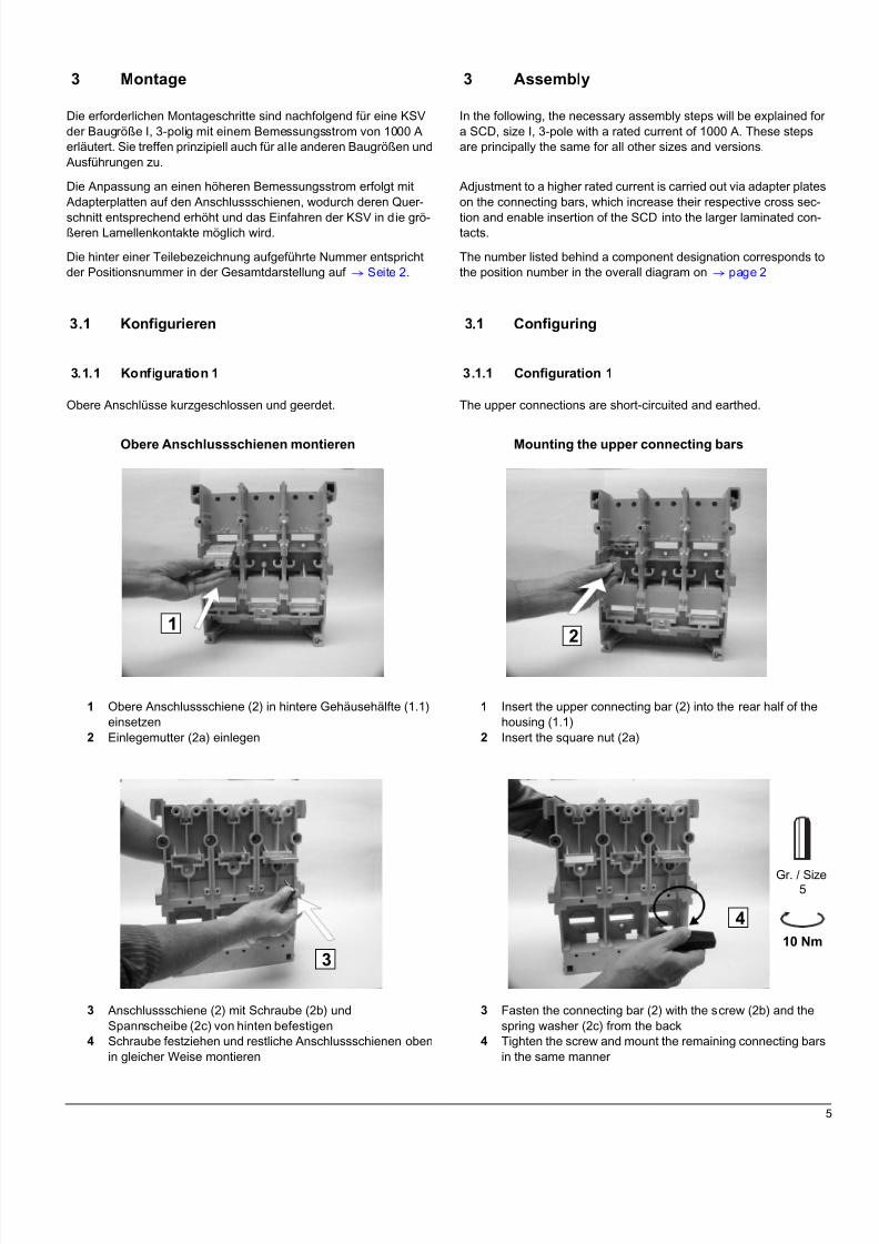
3 Montage
Die erforderlichen Montageschritte sind nachfolgend für eine KSVder Baugröße I, 3-polig mit einem Bemessungsstrom von 1000 Aerläutert. Sie treffen prinzipiell auch für alle anderen Baugrößen undAusführungen zu.
Die Anpassung an einen höheren Bemessungsstrom erfolgt mitAdapterplatten auf den Anschlussschienen, wodurch deren Quer-
schnitt entsprechend erhöht und das Einfahren der KSV in die grö-ßeren Lamellenkontakte möglich wird.
Die hinter einer Teilebezeichnung aufgeführte Nummer entsprichtder Positionsnummer in der Gesamtdarstellung auf q Seite 2 .
3.1 Konfigurieren
3.1.1 Konfiguration 1
Obere Anschlüsse kurzgeschlossen und geerdet.
Obere Anschlussschienen montieren
1 Obere Anschlussschiene (2) in hintere Gehäusehälfte (1.1)einsetzen
2 Einlegemutter (2a) einlegen
3 Anschlussschiene (2) mit Schraube (2b) undSpannscheibe (2c) von hinten befestigen
4 Schraube festziehen und restliche Anschlussschienen obenin gleicher Weise montieren
12
10 Nm
Gr. / Size5
3
4
3 Assembly
In the following, the necessary assembly steps will be explained fora SCD, size I, 3-pole with a rated current of 1000 A. These stepsare principally the same for all other sizes and versions.
Adjustment to a higher rated current is carried out via adapter plateson the connecting bars, which increase their respective cross sec-
tion and enable insertion of the SCD into the larger laminated con-tacts.
The number listed behind a component designation corresponds tothe position number in the overall diagram on q page 2
3.1 Configuring
3.1.1 Configuration 1
The upper connections are short-circuited and earthed.
Mounting the upper connecting bars
1 Insert the upper connecting bar (2) into the rear half of thehousing (1.1)
2 Insert the square nut (2a)
3 Fasten the connecting bar (2) with the screw (2b) and thespring washer (2c) from the back
4 Tighten the screw and mount the remaining connecting barsin the same manner
8/9/2019 Dispositivo de aterramento e curto circuito.PDF
http://slidepdf.com/reader/full/dispositivo-de-aterramento-e-curto-circuitopdf 8/22
6
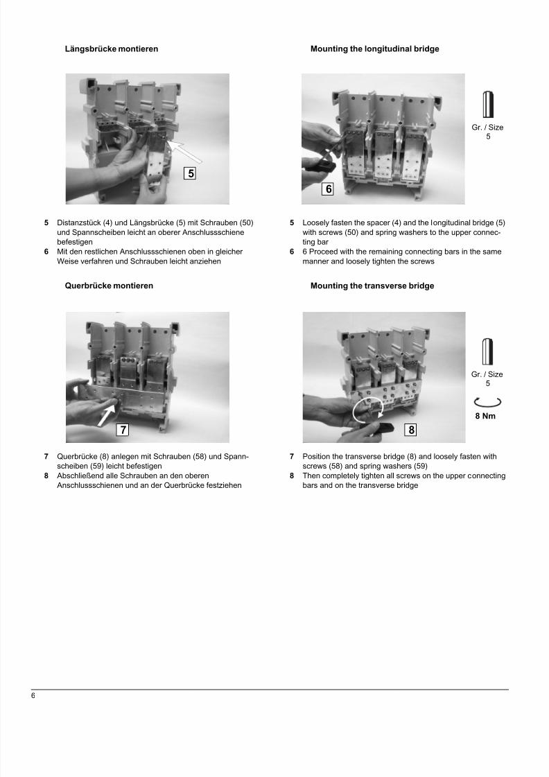
Längsbrücke montieren
5 Distanzstück (4) und Längsbrücke (5) mit Schrauben (50)und Spannscheiben leicht an oberer Anschlussschienebefestigen
6 Mit den restlichen Anschlussschienen oben in gleicherWeise verfahren und Schrauben leicht anziehen
Querbrücke montieren
7 Querbrücke (8) anlegen mit Schrauben (58) und Spann-scheiben (59) leicht befestigen
8 Abschließend alle Schrauben an den oberenAnschlussschienen und an der Querbrücke festziehen
56
Gr. / Size5
8 Nm
Gr. / Size5
87
Mounting the longitudinal bridge
5 Loosely fasten the spacer (4) and the longitudinal bridge (5)with screws (50) and spring washers to the upper connec-ting bar
6 6 Proceed with the remaining connecting bars in the samemanner and loosely tighten the screws
Mounting the transverse bridge
7 Position the transverse bridge (8) and loosely fasten withscrews (58) and spring washers (59)
8 Then completely tighten all screws on the upper connectingbars and on the transverse bridge
8/9/2019 Dispositivo de aterramento e curto circuito.PDF
http://slidepdf.com/reader/full/dispositivo-de-aterramento-e-curto-circuitopdf 9/22
7
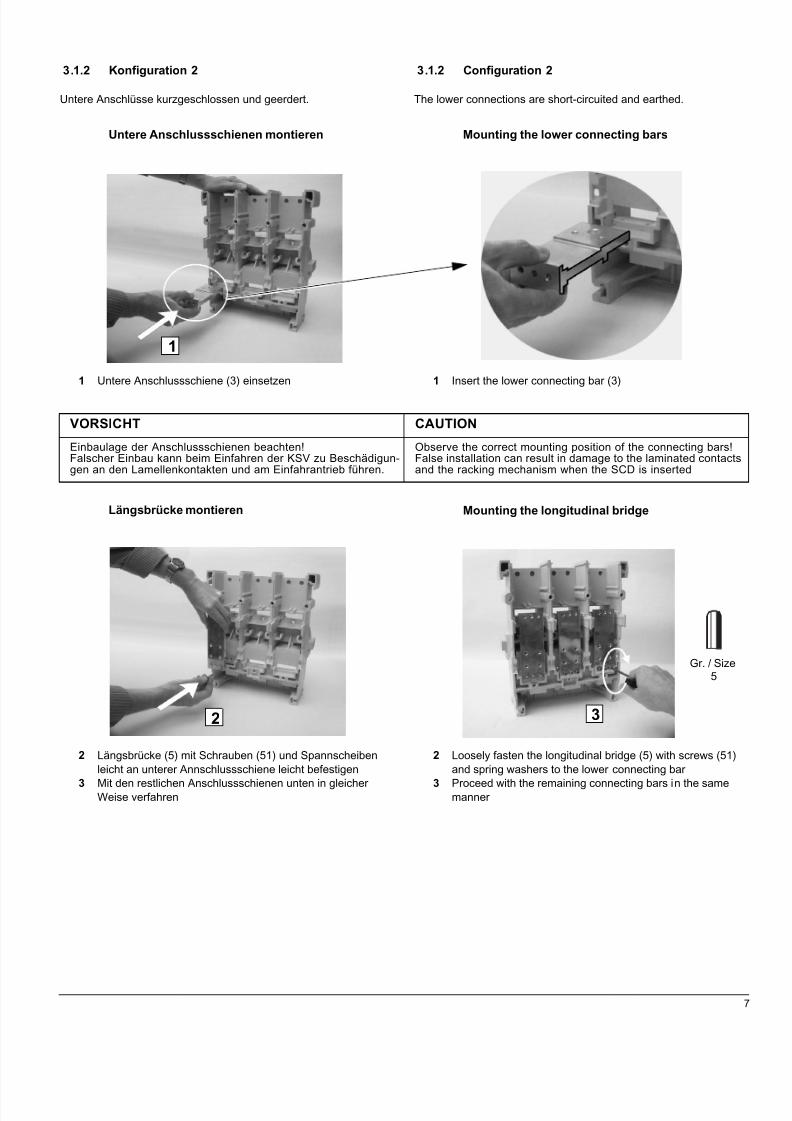
3.1.2 Konfiguration 2
Untere Anschlüsse kurzgeschlossen und geerdert.
Untere Anschlussschienen montieren
1 Untere Anschlussschiene (3) einsetzen
Längsbrücke montieren
2 Längsbrücke (5) mit Schrauben (51) und Spannscheibenleicht an unterer Annschlussschiene leicht befestigen
3 Mit den restlichen Anschlussschienen unten in gleicherWeise verfahren
VORSICHT CAUTION
Einbaulage der Anschlussschienen beachten!Falscher Einbau kann beim Einfahren der KSV zu Beschädigun-gen an den Lamellenkontakten und am Einfahrantrieb führen.
Observe the correct mounting position of the connecting bars!False installation can result in damage to the laminated contactsand the racking mechanism when the SCD is inserted
1
2 3
3.1.2 Configuration 2
The lower connections are short-circuited and earthed.
Mounting the lower connecting bars
1 Insert the lower connecting bar (3)
Mounting the longitudinal bridge
2 Loosely fasten the longitudinal bridge (5) with screws (51)and spring washers to the lower connecting bar
3 Proceed with the remaining connecting bars in the samemanner
Gr. / Size5

8/9/2019 Dispositivo de aterramento e curto circuito.PDF
http://slidepdf.com/reader/full/dispositivo-de-aterramento-e-curto-circuitopdf 10/22
8
Querbrücke montieren
4 Querbrücke (8) anlegen und mit Schrauben (58) und Spann-scheiben (59) leicht befestigen
5 Abschließend alle Schrauben an den unteren Anschlüssenund an der Querbrücke festziehen
3.1.3 Konfiguration 3
Obere und untere Anschlüsse überbrückt, kurzgeschlossen undgeerdet.
Obere Anschlussschienen montieren
Arbeitsschritte 1 - 4 auf q Seite 5
Untere Anschlussschienen einsetzen
1 Alle unteren Anschlussschienen (3) einsetzen
VORSICHT CAUTION
Einbaulage der Anschlussschienen beachten!Falscher Einbau kann beim Einfahren der KSV zu Beschädigun-gen an den Lamellenkontakten und am Einfahrantrieb führen.
Observe the correct mounting position of the connecting bars!False installation can result in damage to the laminated contactsand the racking mechanism when the SCD is inserted.
45 8 Nm
Gr. / Size5
1
Mounting the transverse bridge
4 Position the transverse bridge (8) and loosely tighten withscrews (58) and spring washers (59)
5 Then completely tighten all screws on the lower connectionsand on the transverse bridge
3.1.3 Configuration 3
The upper and lower connections are jumped, short-circuited andearthed.
Mounting the upper connecting bars
Follow steps 1 - 4 on q page 5
Inserting the lower connecting bars
1 1 Insert all lower connecting bars (3)
8/9/2019 Dispositivo de aterramento e curto circuito.PDF
http://slidepdf.com/reader/full/dispositivo-de-aterramento-e-curto-circuitopdf 11/22
9
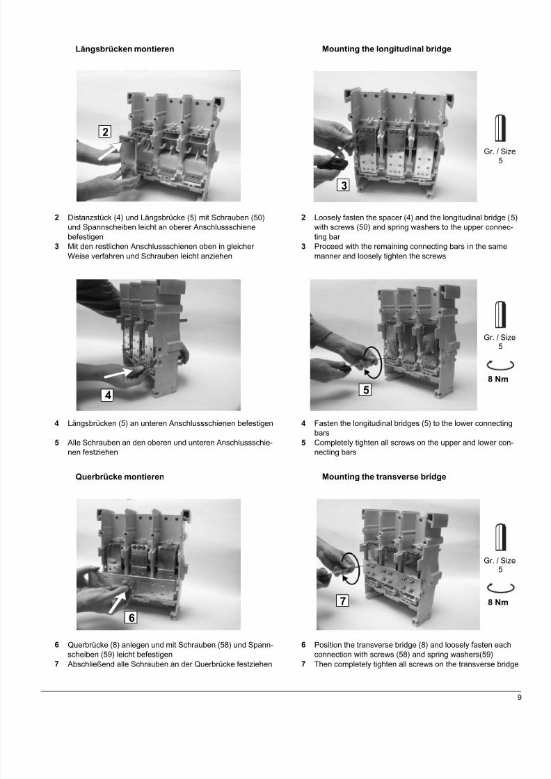
Längsbrücken montieren
2 Distanzstück (4) und Längsbrücke (5) mit Schrauben (50)und Spannscheiben leicht an oberer Anschlussschienebefestigen
3 Mit den restlichen Anschlussschienen oben in gleicherWeise verfahren und Schrauben leicht anziehen
4 Längsbrücken (5) an unteren Anschlussschienen befestigen
5 Alle Schrauben an den oberen und unteren Anschlussschie-nen festziehen
Querbrücke montieren
6 Querbrücke (8) anlegen und mit Schrauben (58) und Spann-scheiben (59) leicht befestigen
7 Abschließend alle Schrauben an der Querbrücke festziehen
2
3
Gr. / Size5
4
8 Nm
Gr. / Size5
67 8 Nm
Gr. / Size5
Mounting the longitudinal bridge
2 Loosely fasten the spacer (4) and the longitudinal bridge (5)with screws (50) and spring washers to the upper connec-ting bar
3 Proceed with the remaining connecting bars in the samemanner and loosely tighten the screws
4 Fasten the longitudinal bridges (5) to the lower connectingbars
5 Completely tighten all screws on the upper and lower con-necting bars
Mounting the transverse bridge
6 Position the transverse bridge (8) and loosely fasten eachconnection with screws (58) and spring washers(59)
7 Then completely tighten all screws on the transverse bridge
5
8/9/2019 Dispositivo de aterramento e curto circuito.PDF
http://slidepdf.com/reader/full/dispositivo-de-aterramento-e-curto-circuitopdf 12/22
10
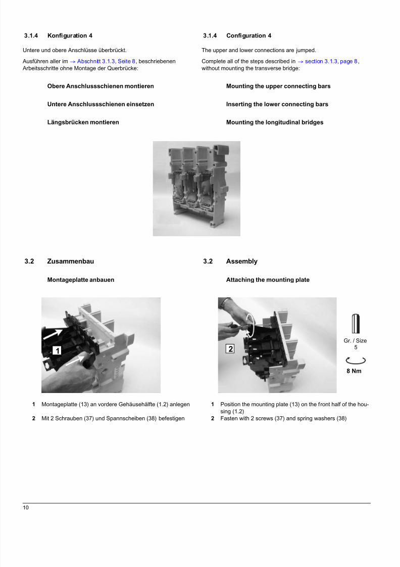
3.1.4 Konfiguration 4
Untere und obere Anschlüsse überbrückt.
Ausführen aller im q Abschnitt 3.1.3, Seite 8, beschriebenenArbeitsschritte ohne Montage der Querbrücke:
Obere Anschlussschienen montieren
Untere Anschlussschienen einsetzen
Längsbrücken montieren
3.2 Zusammenbau
Montageplatte anbauen
1 Montageplatte (13) an vordere Gehäusehälfte (1.2) anlegen
2 Mit 2 Schrauben (37) und Spannscheiben (38) befestigen
1 2
8 Nm
Gr. / Size5
3.1.4 Configuration 4
The upper and lower connections are jumped.
Complete all of the steps described in q section 3.1.3, page 8 ,without mounting the transverse bridge:
Mounting the upper connecting bars
Inserting the lower connecting bars
Mounting the longitudinal bridges
3.2 Assembly
Attaching the mounting plate
1 Position the mounting plate (13) on the front half of the hou-sing (1.2)
2 Fasten with 2 screws (37) and spring washers (38)

8/9/2019 Dispositivo de aterramento e curto circuito.PDF
http://slidepdf.com/reader/full/dispositivo-de-aterramento-e-curto-circuitopdf 13/22
11
Vordere und hintere Gehäusehälftenzusammenschrauben
3 Vordere (1.2) und hintere (1.1) Gehäusehälften zusammen-fügen
4 An den oberen Anschlussschienen außen dieSchrauben (1a) mit Spannscheiben (1c) und innen dieSchrauben (1b) mit Spannscheiben (1c) einsetzen
5 Schrauben festziehen
6 An den unteren Anschlussschienen außen dieSchrauben (1d) mit Spannscheiben (1c) und innen dieSchrauben (1e) mit Spannscheiben (1c) einsetzen
7 Schrauben festziehen
3
BG I/II
Gr. / Size64 5
BG III
18 Nm 25 Nm
Gr. / Size8
67
Screwing the front and rear halves of the housingtogether
3 Position the front (1.2) and the rear (1.1) halves of the hou-sing to form one unit
4 Insert the screws (1a) with spring washers (1c) on the out-side of the upper connecting bars and the screws (1b) withspring washers (1c) on the inside of the upper connectingbars
5 Tighten the screws
6 Insert the screws (1d) with spring washers (1c) on the out-side of the lower connecting bars and the screws (1e) withspring washers (1c) on the inside of the lower connectingbars
7 Tighten the screws
BG I/II
Gr. / Size6
BG III
12 Nm 18 Nm
Gr. / Size6

8/9/2019 Dispositivo de aterramento e curto circuito.PDF
http://slidepdf.com/reader/full/dispositivo-de-aterramento-e-curto-circuitopdf 14/22
12
Wandlerabdeckungen anschrauben
8 Wandlerabdeckungen (15) aufsetzen9 Mit Schrauben (15a) und Spannscheiben (15b) befestigen
Lichtbogenkammerdeckel aufsetzen
10 Lichtbogenkammerdeckel (10) einschieben11 Mit Schrauben (11) und Spannscheiben (11a) befestigen
Schalterfüße montieren
12 KSV auf die Seite kippen und Fuß (16) in Nuten einschieben
13 Nase in Fuß einrasten
10 Nm
Gr. / Size5
8
9
5 Nm
1110
PH 2
12
13
Attaching the transformer covers
8 Position the transformer cover (15)9 Fasten with screws (15a) and spring washers (15b)
Mounting the arc chute cover
10 Insert the arc chute cover (10)11 Fasten with screws (11) and spring washers (11a)
Mounting the circuit-breaker feet
12 Tip the SCD onto its side and insert the foot (16) into thegrooves
13 Click the nose into the foot

8/9/2019 Dispositivo de aterramento e curto circuito.PDF
http://slidepdf.com/reader/full/dispositivo-de-aterramento-e-curto-circuitopdf 15/22
13
14 3 Schrauben (16a) einsetzen15 Schrauben festziehen
Zweiten Fuß in gleicher Weise anbauen.
Querbrücke erden
Entfällt, wenn Querbrücke nicht eingebaut.
16 Querschiene mit je 2 Schrauben (58) undSpannscheiben (59) mit beiden Füßen verschrauben
17 Schrauben festziehen
18 Erdungskontakte (19) mit je 2 Schrauben (19a) an beideFüße anbauen
19 Schrauben festziehen
10 Nm
Gr. / Size4
14 15
8 Nm
Gr. / Size5
16 17
3 Nm
Gr. / Size3
18 19
14 Insert 3 screws (16a)15 Tighten the screws
Attach the second foot in the same manner.
Earthing the transverse bridge
Not applicable if the transverse bridge is not attached.
16 Screw the transverse bridge with 2 screws (58) and springwashers (59) each to the two feet
17 Tighten the screws
18 Attach the ground contacts (19) with 2 screws (19a) each tothe respective feet
19 Tighten the screws
8/9/2019 Dispositivo de aterramento e curto circuito.PDF
http://slidepdf.com/reader/full/dispositivo-de-aterramento-e-curto-circuitopdf 16/22
14
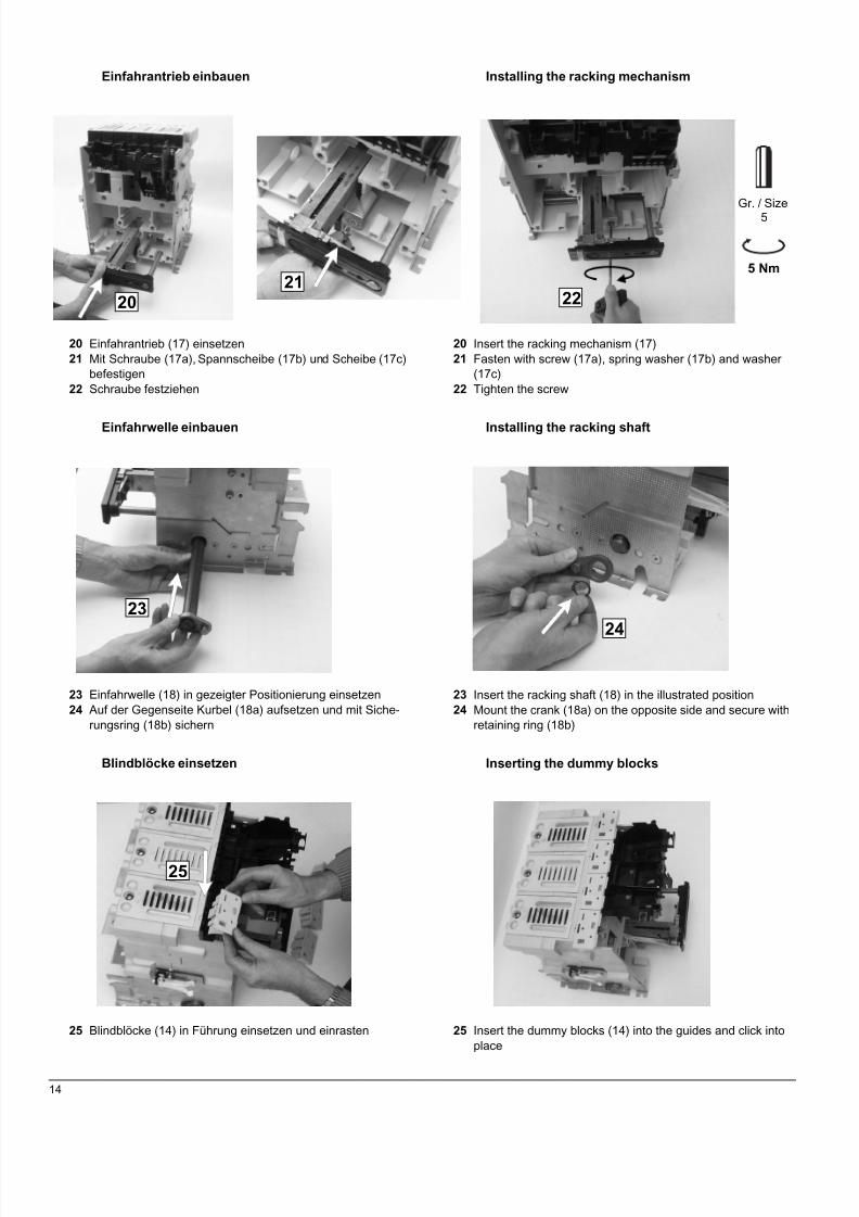
Einfahrantrieb einbauen
20 Einfahrantrieb (17) einsetzen21 Mit Schraube (17a), Spannscheibe (17b) und Scheibe (17c)
befestigen22 Schraube festziehen
Einfahrwelle einbauen
23 Einfahrwelle (18) in gezeigter Positionierung einsetzen24 Auf der Gegenseite Kurbel (18a) aufsetzen und mit Siche-
rungsring (18b) sichern
Blindblöcke einsetzen
25 Blindblöcke (14) in Führung einsetzen und einrasten
5 Nm
Gr. / Size5
2021
22
2324
25
Installing the racking mechanism
20 Insert the racking mechanism (17)21 Fasten with screw (17a), spring washer (17b) and washer
(17c)22 Tighten the screw
Installing the racking shaft
23 Insert the racking shaft (18) in the illustrated position24 Mount the crank (18a) on the opposite side and secure with
retaining ring (18b)
Inserting the dummy blocks
25 Insert the dummy blocks (14) into the guides and click intoplace
8/9/2019 Dispositivo de aterramento e curto circuito.PDF
http://slidepdf.com/reader/full/dispositivo-de-aterramento-e-curto-circuitopdf 17/22
15
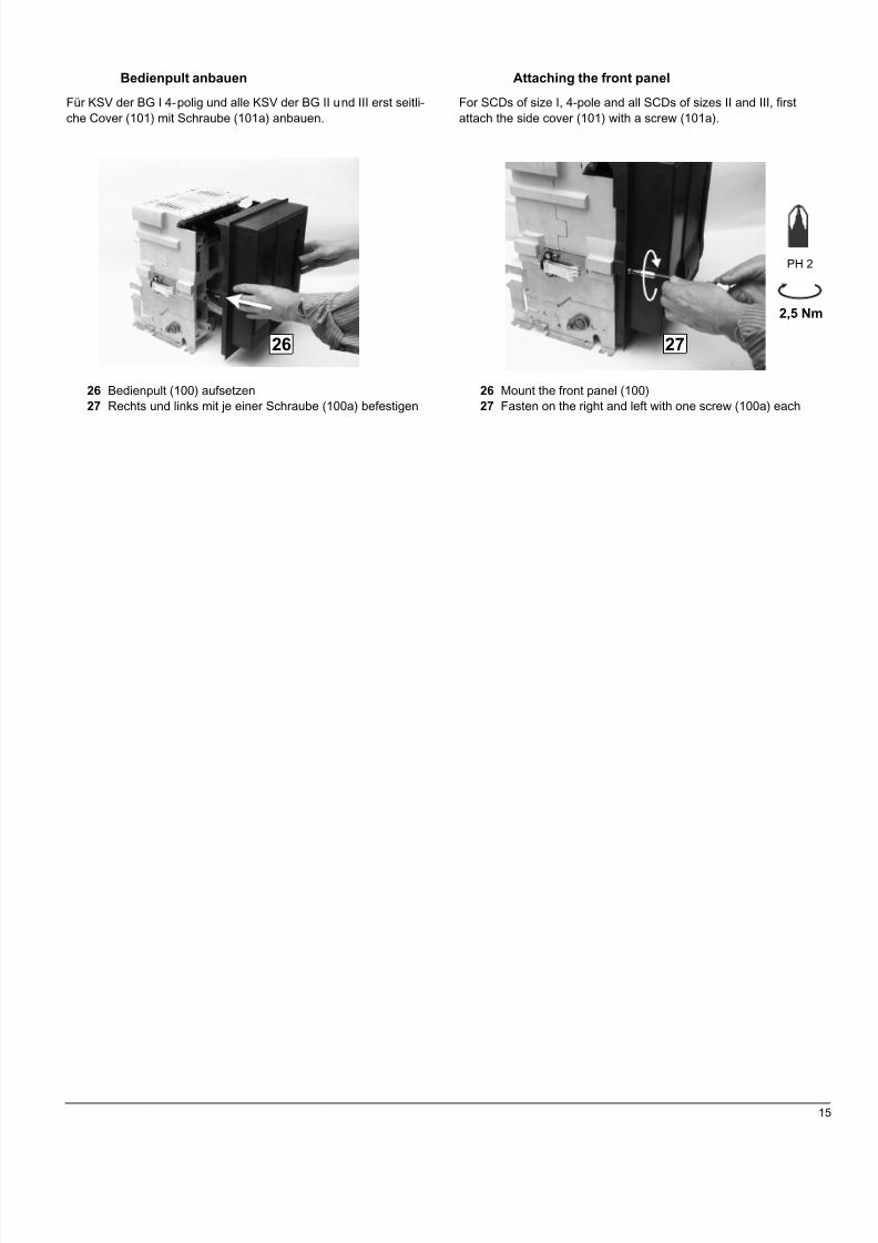
Bedienpult anbauen
Für KSV der BG I 4-polig und alle KSV der BG II und III erst seitli-che Cover (101) mit Schraube (101a) anbauen.
26 Bedienpult (100) aufsetzen27 Rechts und links mit je einer Schraube (100a) befestigen
2,5 Nm
26 27
PH 2
Attaching the front panel
For SCDs of size I, 4-pole and all SCDs of sizes II and III, firstattach the side cover (101) with a screw (101a).
26 Mount the front panel (100)27 Fasten on the right and left with one screw (100a) each
8/9/2019 Dispositivo de aterramento e curto circuito.PDF
http://slidepdf.com/reader/full/dispositivo-de-aterramento-e-curto-circuitopdf 18/22
16
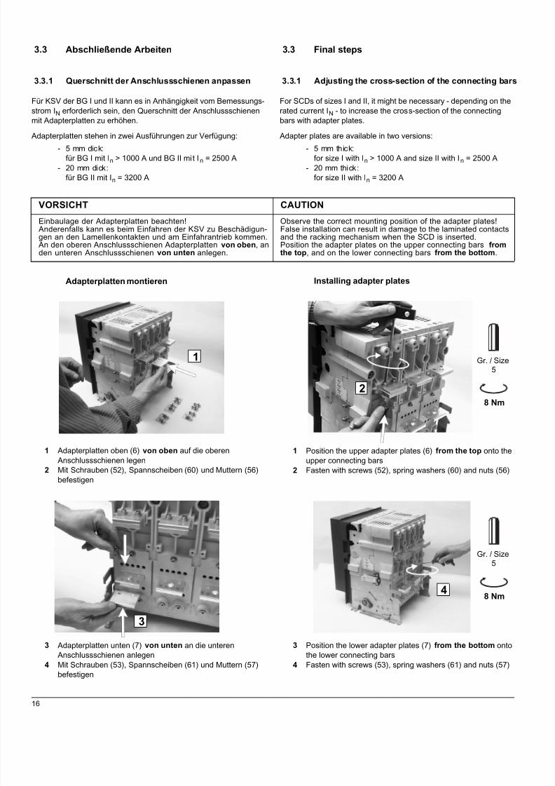
3.3 Abschließende Arbeiten
3.3.1 Querschnitt der Anschlussschienen anpassen
Für KSV der BG I und II kann es in Anhängigkeit vom Bemessungs-strom IN erforderlich sein, den Querschnitt der Anschlussschienenmit Adapterplatten zu erhöhen.
Adapterplatten stehen in zwei Ausführungen zur Verfügung:- 5 mm dick:
für BG I mit In > 1000 A und BG II mit In = 2500 A- 20 mm dick:
für BG II mit In = 3200 A
Adapterplatten montieren
1 Adapterplatten oben (6) von oben auf die oberenAnschlussschienen legen
2 Mit Schrauben (52), Spannscheiben (60) und Muttern (56)befestigen
3 Adapterplatten unten (7) von unten an die unterenAnschlussschienen anlegen
4 Mit Schrauben (53), Spannscheiben (61) und Muttern (57)befestigen
VORSICHT CAUTION
Einbaulage der Adapterplatten beachten!Anderenfalls kann es beim Einfahren der KSV zu Beschädigun-gen an den Lamellenkontakten und am Einfahrantrieb kommen.An den oberen Anschlussschienen Adapterplatten von oben , anden unteren Anschlussschienen von unten anlegen.
Observe the correct mounting position of the adapter plates!False installation can result in damage to the laminated contactsand the racking mechanism when the SCD is inserted.Position the adapter plates on the upper connecting bars fromthe top , and on the lower connecting bars from the bottom .
8 Nm
Gr. / Size5
2
1
3
48 Nm
Gr. / Size5
3.3 Final steps
3.3.1 Adjusting the cross-section of the connecting bars
For SCDs of sizes I and II, it might be necessary - depending on therated current IN - to increase the cross-section of the connectingbars with adapter plates.
Adapter plates are available in two versions:- 5 mm thick:
for size I with In > 1000 A and size II with In = 2500 A- 20 mm thick:
for size II with In = 3200 A
Installing adapter plates
1 Position the upper adapter plates (6) from the top onto theupper connecting bars
2 Fasten with screws (52), spring washers (60) and nuts (56)
3 Position the lower adapter plates (7) from the bottom ontothe lower connecting bars
4 Fasten with screws (53), spring washers (61) and nuts (57)

8/9/2019 Dispositivo de aterramento e curto circuito.PDF
http://slidepdf.com/reader/full/dispositivo-de-aterramento-e-curto-circuitopdf 19/22
17
3.3.2 Nennstromkodierung
Nach dem Zusammenbau der KSV ist die Nennstromkodierung ent-sprechend Betriebsanleitung für den LeistungsschalterSENTRON WL, Kapitel 18 Zusatzausrüstungen für Einschubrah-men, Abschnitt Kodierung Schalter - Einschubrahmen, durchzufüh-ren. Dafür sind die mitgelieferten beiden Kodierstücke (20) mitSchraube (36) zu verwenden.
3.3.3 Klebeschild
Entsprechend der gewählten Konfiguration der KSV ist auf demBedienpult das zutreffende Klebeschild (102 - 105) anzubringen.
4 Bedienung
Hinweise zur Bedienung der KSV, wie:- Einsetzen in den Einschubrahmen- Verfahren in Betriebsstellung- Entnehmen aus dem Einschubrahmen
sind der Betriebsanleitung für den LeistungsschalterSENTRON WL, Kapitel 6 und 24, zu entnehmen.
5 Umrüsten
5.1 Konfiguration ändern
Sollte es erforderlich sein, die KSV auf eine andere Konfigurationumzurüsten, sind folgende Arbeitsschritte durchzuführen:
- KSV aus dem Einschubrahmen entnehmen- KSV in umgekehrter Reihenfolge, wie imq Abschnitt 3.2,
Seite 10, beschrieben, demontieren.Dabei brauchen folgende Arbeitsschritte nicht ausgeführtwerden:25 Blindblöcke ausbauen20 ... 22 Einfahrantrieb ausbauen18, 19 Erdungskontakt abbauen1, 2 Montageplatte abbauen
- Ändern der Konfiguration- KSV zusammenbauen- Klebeschild entsprechend neuer Konfiguration anbringen
3.3.2 Rated current coding
After the SCD has been assembled, the rated current coding mustbe carried out according to the operating instructions for the SEN-TRON WL circuit-breaker, Chapter 18 Additional Equipment forGuide Frames, Section Coding of Circuit-Breakers - Guide Frames.To do so, use both of the supplied coding elements (20) withscrews (36).
3.3.3 Labels
According to the selected configuration of the SCD, the respectivelabel (102 - 105) must be attached to the front panel.
4 Operation
For information concerning the operation of the SCD, e.g.:- Inserting into the guide frame- Racking into connected position- Removing from the guide frame
please refer to the Operating Instructions for the SENTRON WL Cir-cuit-Breakers, Chapter 6 and 24.
5 Conversion
5.1 Changing configuration
Should it become necessary to convert the SCD to another configu-ration, the following steps must be carried out:
- Remove the SCD from the guide frame- Disassemble the SCD in the reverse order of that descri-
bed in q section 3.2, page 10 .The following steps, however, need not be carried out:
25 Removing the dummy blocks20 ... 22 Removing the racking mechanism18, 19 Removing the earthing contact1, 2 Removing the mounting plate
- Change the configuration- Assemble the SCD- Attach the respective label for the new configuration
8/9/2019 Dispositivo de aterramento e curto circuito.PDF
http://slidepdf.com/reader/full/dispositivo-de-aterramento-e-curto-circuitopdf 20/22
18
5.2 Zulässigen Bemessungsstrom ändern
Es ist möglich, die KSV auf einen anderen für die jeweilige Bau-größe zulässigen Bemessungsstrom umzurüsten. Dazu ist wie folgtzu verfahren:
Querschnitt der Anschlussschienen anpassen
q Abschnitt 3.3.1, Seite 16
Nennstromkodierung entsprechend anpassen
q Abschnitt 3.3.2, Seite 17
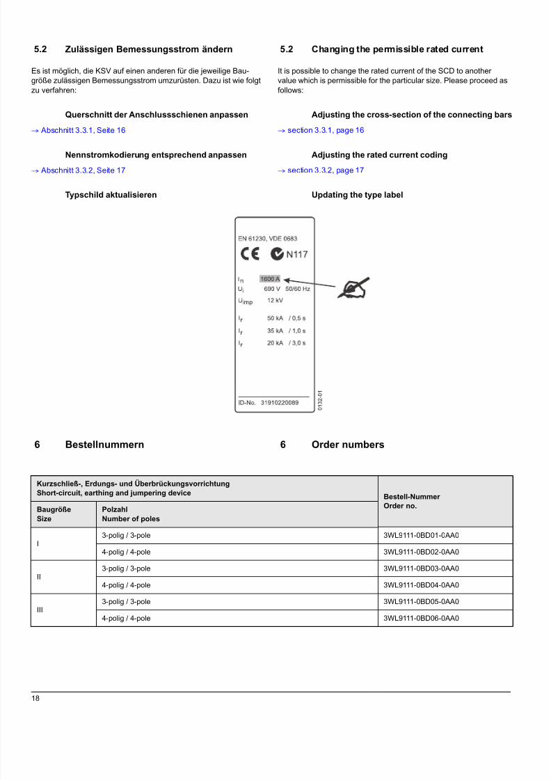
Typschild aktualisieren
6 Bestellnummern
Kurzschließ-, Erdungs- und ÜberbrückungsvorrichtungShort-circuit, earthing and jumpering device Bestell-Nummer
Order no.BaugrößeSize
PolzahlNumber of poles
I
3-polig / 3-pole 3WL9111-0BD01-0AA0
4-polig / 4-pole 3WL9111-0BD02-0AA0
II3-polig / 3-pole 3WL9111-0BD03-0AA0
4-polig / 4-pole 3WL9111-0BD04-0AA0
III3-polig / 3-pole 3WL9111-0BD05-0AA0
4-polig / 4-pole 3WL9111-0BD06-0AA0
5.2 Changing the permissible rated current
It is possible to change the rated current of the SCD to anothervalue which is permissible for the particular size. Please proceed asfollows:
Adjusting the cross-section of the connecting bars
q section 3.3.1, page 16
Adjusting the rated current coding
q section 3.3.2, page 17
Updating the type label
6 Order numbers

8/9/2019 Dispositivo de aterramento e curto circuito.PDF
http://slidepdf.com/reader/full/dispositivo-de-aterramento-e-curto-circuitopdf 21/22

8/9/2019 Dispositivo de aterramento e curto circuito.PDF
http://slidepdf.com/reader/full/dispositivo-de-aterramento-e-curto-circuitopdf 22/22
Technical Support: Tel: ++49 (0) 9131-7-43833 (8°° - 17°° MEZ/CET) Fax: ++49 (0) 9131-7-42899