dissertation - design of a formula student race car spring, damper and anti-roll system
TRANSCRIPT

Design of a Formula Student
Race car Spring, Damper
and Anti-roll Bar System By Keiran Anthony Stigant
XE337 – Group project
Supervisor: Dr Khizer Saeed
March 2015
Final year report submitted in partial fulfilment of the requirements for the degree of Bachelor of Science (Honours) in Automotive Engineering.

Disclaimer I hereby certify that the attached report is my own work except where otherwise indicated. I
have identified my sources of information; in particular I have put in quotation marks any
passages that have been quoted word-for-word, and identified their origin.
Signed…………………………………………
Date…………………………………………...

Abstract A team of students at the University of Brighton have been given the opportunity to take part
in the design of a race car to compete in the Formula Student race series.
The subject of this report contains the design of the spring, damper and anti-roll systems
including: the chassis kinematics, motion analysis, individual component design and all
supporting material including: possible limitations, rules, regulations and group contribution
within the project.
The principle of a suspension system is explained and then further detail is applied to the
design of the spring, damper and anti-roll system including: possible design solutions,
reasoning behind the chosen designs, calculated data to support the design, stress analysis and
visual representations of the final solutions.
The result of the project is a system that could be manufactured and applied to the vehicle for
use within the competition that conforms to rules, regulations and meets the specified
requirements.
The data, methods and concepts used within the report aren’t just specific to a race car, they
can be used widely within the automotive industry to provide solutions for many scenarios if
used in the correct manner.

Contents
1. Introduction ............................................................................................................................. 1
2. Suspension System .................................................................................................................. 2
2.1. Suspension principle ............................................................................................................. 2
2.2. System Requirements....................................................................................................... 2
2.3. Spring and damper arrangement concepts…….………………….………..…...……4
3. Spring and damper arrangement selection………….……………..……………………….5
3.1. Anti-roll bar………………….…………………………………….………………………6
3.2. Anti-roll bar arrangement concepts ….......................................………………………6
4. Anti-roll bar arrangement selection………….……………………………………………..7
5. Chassis kinematics……………………...…………………………………………………….8
5.1 Roll axis definition……….......……………………………………………………………..8
5.2 Primary roll moments……………………………………………….....………………..9
5.3 Unsprung moments and total roll moment……………………….......………………9
5.4 Resistive moments……………………………….......…………………………..10
5.5 Weight transfer……………………….......…………………………………..12
6. Damper Choice……………………….....…………………………………………………….12
7. Spring Design….........................................................................................................................14
8. Front spring, damper and anti-roll system design…………………………………………15
8.1 Working principle………………………………………………………………………..15
8.2 Final Design overview………………………………………………………………15
8.3 Bump motion ratio……………………………………………………………...16
8.4 Front Pull rod design………………………………………........................17
8.5 Front Rocker design………………………………………………..…19
8.6 Front Anti-roll design………………………………………….…20
9. Rear spring and damper design……………………………………………………….……..22
9.1 Final design overview…………….……………………………………………………..22
9.2 Bump motion ratio…………………………………………………………………23
9.3 Rear push rod design………………………………………………………….24
9.4 Rear Rocker design………………………………………………………..24
10. Conclusion…………………………………………………………………………………....25

11. Recommendations…………………………………………………………………………... 25
References……………………………………………………………….…………………….…26
Appendix A – Decision matrix criteria……………………………………...…………….……27
Appendix B – Roll axis Definition………………………………………………………………29
Appendix C – Equations used…………………………………………………..………………34
Appendix D – Resistive moments……………………………………………………………….36
Appendix E – Spring design…………………………………………………………………….38
Appendix F – Final designs……………………………………………………………………...39
1
1 Introduction
The students at the University of Brighton have been given the opportunity to take part in
the design of a race car to compete in the Formula Student competition. Formula Student
began its life in the United States in 1981 by the Society of Automotive Engineers (SAE) and
has been a global success since. The overall goal of Formula student is to provide students
with the opportunity and experience of taking part in all aspects of Engineering including;
management, design, manufacturing, marketing and to increase the ‘people skills’ of the
students by working as part of a large team. The way in which this is conducted is by
enabling the students to design, develop and manufacture a single seated race car. In Europe,
there are four races available, these are hosted in the Germany, Austria, Italy and the United
Kingdom by the Institute of Mechanical Engineers (IMechE), who have hosted the European
division of Formula student since 1998.
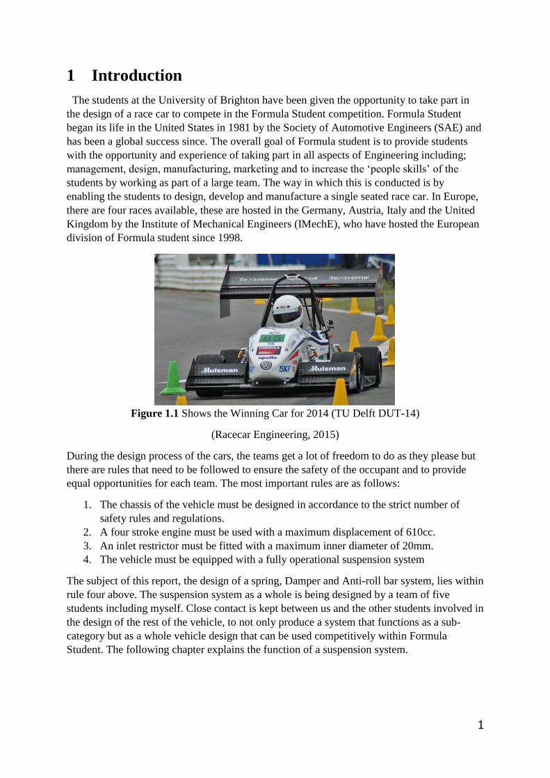
Figure 1.1 Shows the Winning Car for 2014 (TU Delft DUT-14)
(Racecar Engineering, 2015)
During the design process of the cars, the teams get a lot of freedom to do as they please but
there are rules that need to be followed to ensure the safety of the occupant and to provide
equal opportunities for each team. The most important rules are as follows:
1. The chassis of the vehicle must be designed in accordance to the strict number of
safety rules and regulations.
2. A four stroke engine must be used with a maximum displacement of 610cc.
3. An inlet restrictor must be fitted with a maximum inner diameter of 20mm.
4. The vehicle must be equipped with a fully operational suspension system
The subject of this report, the design of a spring, Damper and Anti-roll bar system, lies within
rule four above. The suspension system as a whole is being designed by a team of five
students including myself. Close contact is kept between us and the other students involved in
the design of the rest of the vehicle, to not only produce a system that functions as a sub-
category but as a whole vehicle design that can be used competitively within Formula
Student. The following chapter explains the function of a suspension system.

2
2 Suspension System
A suspension system compromises of the springs, dampers, linkages, uprights, wheels and
tyres that connect the body of a vehicle to the road surface. How the suspension system is
optimised depends on the vehicle application. For a road car there has to be a compromise
between performance and overall comfort for the users. For a race car the comfort of the
driver is not important and overall performance is what the vehicle must be optimised for.
2.1 Suspension principle
The most important part of a car are the tyres. They transmit all of the drive of the vehicle
through a very small contact area with the road surface. Not only do they transmit the drive,
they also have to handle all braking and steering forces applied by the driver. The purpose of
the suspension system is to keep the tyre contact patch optimal with the road surface to
increase traction. This can be done very effectively in a race car using the correct geometry
and kinematics but often comes at a cost of driver comfort.
2.2 System Requirements
There are two sets of requirements that are required to progress with the design of the spring,
damper and anti-roll system. The first of which are a general set that apply to the whole
vehicle. The second set are specific to the spring, damper and anti-roll system.
The general requirements are as follows:
1. High reliability
2. Low centre of gravity
3. Low weight
4. Aerodynamically efficient
5. Reasonable Costing
6. Must comply with FSAE rules and regulations
The specific requirements for the spring, damper and anti-roll systems are as follows:
1. Adjustability – The system must be as adjustable as possible to suit a wide range of
applications
2. Good accessibility – The whole system must be easily accessible so adjustments and
maintenance can be made with ease.
3. The packaging of the system must not interfere with other vehicle components.
Rules set by the FSAE prescribe: (2015 Formula SAE rules, 2015)
4. Rule T6.1.1 - The car must be equipped with a fully operational suspension system
with shock absorbers, front and rear, with usable wheel travel of at least 50.8 mm (2
inches), 25.4 mm (1 inch) jounce and 25.4 mm (1 inch) rebound, with driver seated.
The judges reserve the right to disqualify cars which do not represent a serious
attempt at an operational suspension system or which demonstrate handling
inappropriate for an autocross circuit.

3
5. Rule T6.1.2 - All suspension mounting points must be visible at Technical Inspection,
either by direct view or by removing any covers.
6. Rule T6.2 - Ground clearance must be sufficient to prevent any portion of the car,
other than the tires, from touching the ground during track events. Intentional or
excessive ground contact of any portion of the car other than the tires will forfeit a run
or an entire dynamic event.
2.3 Spring and Damper arrangement concepts
Firstly the type of spring and damper arrangement must be selected for the vehicle. As a
group, an early decision was made that the vehicle would be equipped with a double
wishbone suspension arm design. The reason for this choice was that it offered the best
adjustability (Four adjustable chassis mounting points), strength (Two suspension arms
opposed to one) and geometry (best control over camber during bump and droop) than any
other system. Looking through a selection of previously successful Formula Student cars, it is
apparent that the vast majority of teams also share the same thought process.
Based on the suspension arm choice, research into potential solutions for the spring, damper
and anti-roll bar could be made to find the most appropriate choice to fulfil the requirements
shown in chapter 2.2:
Outboard coil-over
Positioning a coil-over damper unit in-between the wishbones is a solution that a lot of
modern road vehicles use. Attaching the bottom of the damper directly to the lower wishbone
and then supporting the top of it to the chassis via an inclination angle. The advantages of this
solution lie within packaging constraints and simplicity of design. The disadvantages are that
the motion ratio of the unit is not adjustable and in an open wheel scenario found in Formula
Student, the unit is subject to increasing the aerodynamic drag of the vehicle.
Figure 2.1 Outboard Coil-Over Unit (Car Bibles, 2015)
4
Push rod suspension
Using a push rod system allows the coil-over unit to be mounted “in-board”, within the main
structural part of the chassis of a vehicle. In the case of a push rod design the coil-over unit is
mounted higher than the upper wishbone and fixed at one end. The force during a bump
situation is then transferred through a linkage in a pushing motion (push rod) to a rocker with
a fixed pivot point to the chassis. The rocker can then supply the force to the other end of the
damper via a linkage and rotating on its axis. This can be seen below:
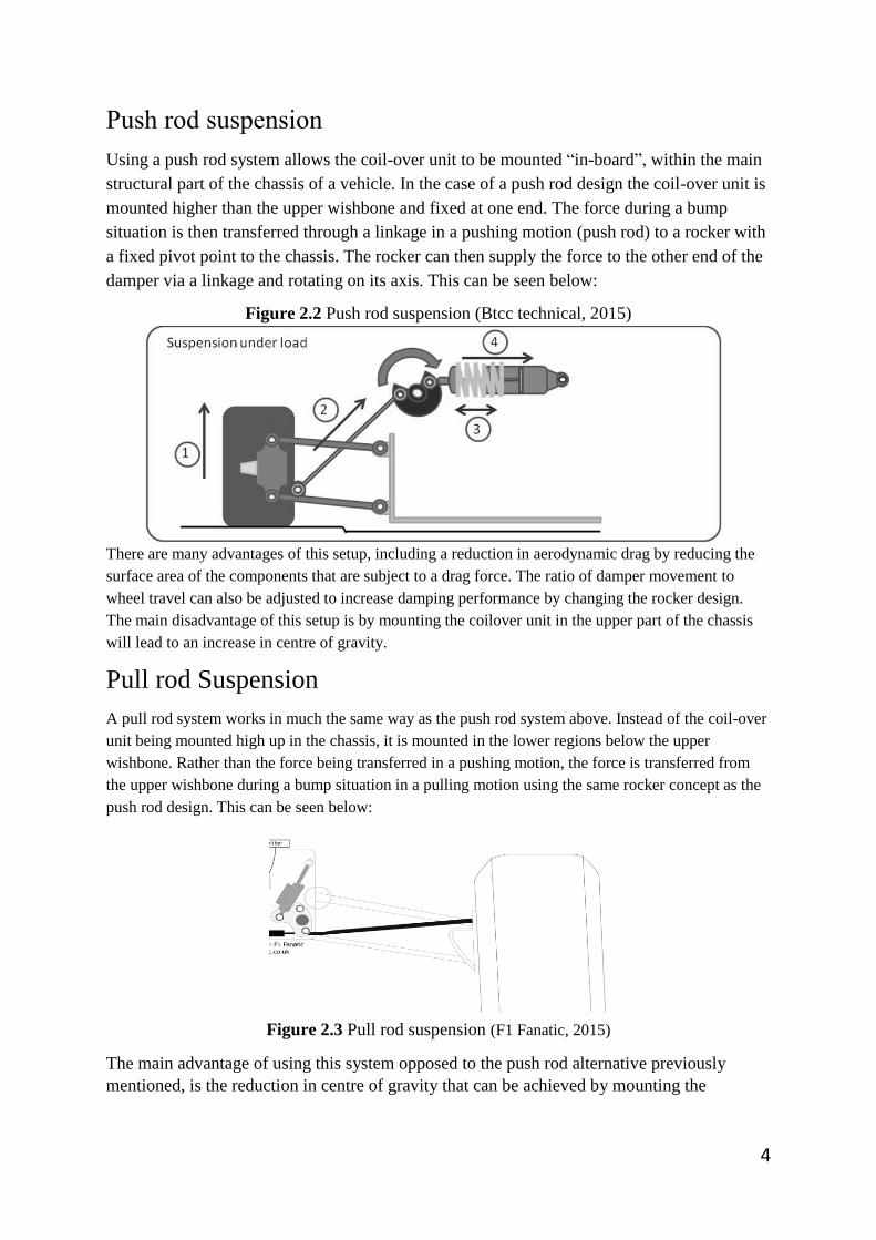
Figure 2.2 Push rod suspension (Btcc technical, 2015)
There are many advantages of this setup, including a reduction in aerodynamic drag by reducing the
surface area of the components that are subject to a drag force. The ratio of damper movement to
wheel travel can also be adjusted to increase damping performance by changing the rocker design.
The main disadvantage of this setup is by mounting the coilover unit in the upper part of the chassis
will lead to an increase in centre of gravity.
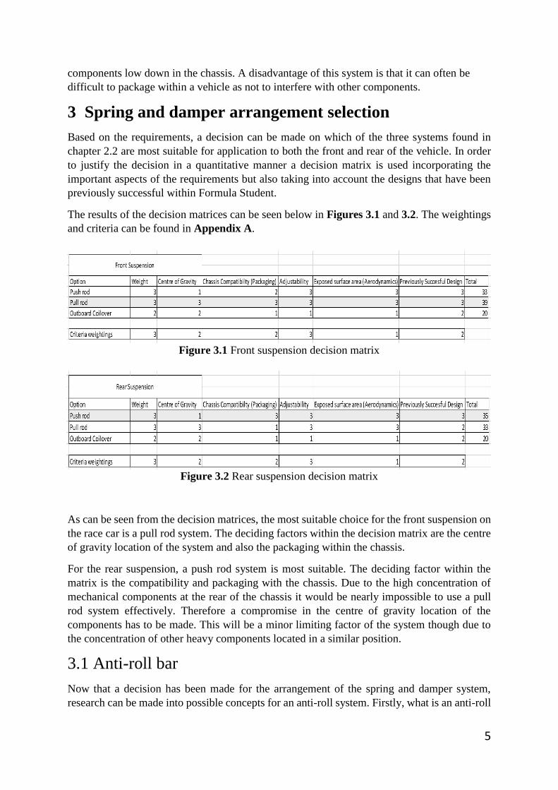
Pull rod Suspension
A pull rod system works in much the same way as the push rod system above. Instead of the coil-over
unit being mounted high up in the chassis, it is mounted in the lower regions below the upper
wishbone. Rather than the force being transferred in a pushing motion, the force is transferred from
the upper wishbone during a bump situation in a pulling motion using the same rocker concept as the
push rod design. This can be seen below:
Figure 2.3 Pull rod suspension (F1 Fanatic, 2015)
The main advantage of using this system opposed to the push rod alternative previously
mentioned, is the reduction in centre of gravity that can be achieved by mounting the
5
components low down in the chassis. A disadvantage of this system is that it can often be
difficult to package within a vehicle as not to interfere with other components.
3 Spring and damper arrangement selection
Based on the requirements, a decision can be made on which of the three systems found in
chapter 2.2 are most suitable for application to both the front and rear of the vehicle. In order
to justify the decision in a quantitative manner a decision matrix is used incorporating the
important aspects of the requirements but also taking into account the designs that have been
previously successful within Formula Student.
The results of the decision matrices can be seen below in Figures 3.1 and 3.2. The weightings
and criteria can be found in Appendix A.
Figure 3.1 Front suspension decision matrix
Figure 3.2 Rear suspension decision matrix
As can be seen from the decision matrices, the most suitable choice for the front suspension on
the race car is a pull rod system. The deciding factors within the decision matrix are the centre
of gravity location of the system and also the packaging within the chassis.
For the rear suspension, a push rod system is most suitable. The deciding factor within the
matrix is the compatibility and packaging with the chassis. Due to the high concentration of
mechanical components at the rear of the chassis it would be nearly impossible to use a pull
rod system effectively. Therefore a compromise in the centre of gravity location of the
components has to be made. This will be a minor limiting factor of the system though due to
the concentration of other heavy components located in a similar position.
3.1 Anti-roll bar
Now that a decision has been made for the arrangement of the spring and damper system,
research can be made into possible concepts for an anti-roll system. Firstly, what is an anti-roll
6
bar? An anti-roll bar is a length of rod that is able to supply an opposing moment from one side
of an axle to the other via a set of linkages. It is used try and reduce the amount in which the
body of the vehicle rolls during cornering by keeping the suspension components as level with
each other as possible. This keeps the tyres of the vehicle as flat to the road surface as possible
increasing the contact area and therefore increasing the level of traction that is able to be
supplied to the road surface.
3.2 Anti-roll bar arrangement concepts
For the chosen spring and damper arrangement there are two possible concepts for how the
Anti-roll bar can be applied to the vehicle. These are as follows:
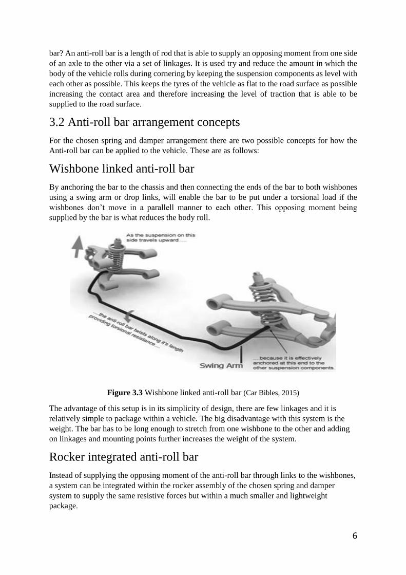
Wishbone linked anti-roll bar
By anchoring the bar to the chassis and then connecting the ends of the bar to both wishbones
using a swing arm or drop links, will enable the bar to be put under a torsional load if the
wishbones don’t move in a parallell manner to each other. This opposing moment being
supplied by the bar is what reduces the body roll.
Figure 3.3 Wishbone linked anti-roll bar (Car Bibles, 2015)
The advantage of this setup is in its simplicity of design, there are few linkages and it is
relatively simple to package within a vehicle. The big disadvantage with this system is the
weight. The bar has to be long enough to stretch from one wishbone to the other and adding
on linkages and mounting points further increases the weight of the system.
Rocker integrated anti-roll bar
Instead of supplying the opposing moment of the anti-roll bar through links to the wishbones,
a system can be integrated within the rocker assembly of the chosen spring and damper
system to supply the same resistive forces but within a much smaller and lightweight
package.

7
Figure 3.4 Rocker integrated anti-roll bar (ScarbsF1, 2015)
The main advantage of this system is that it can be packaged within a small area due to the
size of the components needed. The whole system will weigh a substantial amount less than
the previously mentioned concept and remains highly tuneable.
4 Anti-roll bar arrangement selection
Out of the two possible systems previously explained, there is a clear advantage in integrating
the anti-roll systems of the race car to the rocker assemblies supplied by the spring and
damper arrangement previously determined.
A typical wishbone linked anti-roll bar can weigh in excess of 4kg and is subject to an
aerodynamic drag force due to the majority of the components being mounted outside the
main structural part of the chassis. Whereas a rocker integrated anti-roll bar is more likely to
weigh under 1kg and because it is mounted within the chassis it isn’t subject to reducing the
aerodynamic performance of the vehicle.
There is one minor disadvantage to the system, the complexity of the design. With the
advantages that can be taken from using the design, this is negligible, as the extra time and
effort in the design and development stage will be worth the final outcome.
Based on this, there is no need to produce any quantitative analysis between the two systems
as the rocker integrated anti-roll system would be the clear favourite based on the advantages
previously mentioned.
5 Chassis Kinematics
To progress with the design of the spring, damper and anti-roll systems, there are key aspects
of the chassis that need to be understood. This chapter will explain the kinematics of the
chassis, specifically, the primary moments that need to be resisted in order to supply the
correct handling properties for the vehicle.
By understanding the way in which forces are transferred during cornering will allow the
spring, damper and anti-roll arrangements to be optimised to counteract the forces and keep
the body roll of the vehicle to a minimum. This will then support the function of the
suspension system previously mentioned in Chapter 2.2.

8
5.1 Roll axis definition
Figure 5.1 Roll axis definition data
The first step is to determine the height of both the front (m) and rear (n) roll centre. This is
done using wireframe drawings of the wishbone designs. These can be seen in Appendix B,
Figure B1 and B2. They define the end points at which the vehicle will roll.
An approximation of the vehicles height of centre of mass (h) needs to be found in order to
determine the point in which the mass of the vehicle will act upon the roll centres. At this
stage in the design of the race car, there is very limited information available on component
weights, so an educated approximation must be made to obtain the data needed. This can be
seen in Appendix B, Figure B3.
The next step is to find the longitudinal distances between the front and rear roll centre and
the centre of mass of the vehicle. Again, an approximation needs to be made as to how the
weight is distributed throughout the chassis to locate the longitudinal centre of mass. This can
be seen in Appendix B, Figure B4. The longitudinal distance between the front of the
vehicle and the centre of mass (a) and the longitudinal distance between the rear of the
vehicle and the centre of mass (b) can be seen in Appendix B, Figure B5.
The final steps involve calculating the height of the mean roll centre (RCz mean) and the
value Delta Z. Delta Z is the height of the centre of mass minus the height of the mean roll
centre.
To find the height of the mean roll centre (RCz mean), Equation 1 in appendix C is used.
5.2 Primary roll moments (sprung moments)
Figure 5.2 Primary roll moments

9
The next step is to determine the primary roll moments of the vehicle. Firstly the weight of
the vehicle needs to be found, an approximation of the overall vehicle sprung weight
including the driver can be seen in Appendix B, Figure B4. This weight can then be
represented as a force by multiplying it by gravity (9.81m/s).
A friction coefficient of the tyre to the road surface must be specified as this will determine
the amount of lateral force from the weight of the vehicle will be transferred during
cornering, before the tyre loses traction resulting in a max force. The below quote explains
friction coefficients in detail:
“Jones and Childers report coefficients of friction of about 0.7 for dry roads and 0.4 for wet
roads. The tread design represents an "all weather" compromise. If you were an Indianapolis
race driver, you would use "slick" racing tires with no tread. On dry surfaces you might get as
high as 0.9 as a coefficient of friction, but driving them on wet roads would be dangerous
since the wet road coefficient might be as low as 0.1.” (Jones and Childers, 1994)
During a dry day, the race car will be equipped with slick tyres in order to maximise the
traction, therefore I will base further calculations for the chassis kinematics around a 0.9
coefficient, this will be a “worst case scenario” for the amount of force transferred through
the tyre and suspension components.
Based on the friction coefficient and the weight of the vehicle, a lateral force (mu W) can be
calculated by multiplying the vehicle weight (W) by the Coefficient of friction (mu).
Finally the roll moment of sprung mass (Wx) can be found by multiplying the lateral force
(mu W) by the height of the mean roll centre (RCz mean), found in the previous chapter
(5.1).
5.3 Un-sprung and total roll moments
Figure 5.3 unsprung and total roll moments
Now that the primary roll moments have been found, the un-sprung moments need to be
found. An un-sprung mass needs to be specified for the calculations. “Weight controlled by
the suspension, and usually below the suspension, which forces it into contact with the road
surface or other components, is un-sprung weight.” (Victorylibrary.com, 2015) This includes
such things as the wheels, brakes, wishbones, springs, uprights, dampers and any linkages in-
between the previously mentioned.
Between the group of students including myself designing the suspension system we came to
an agreement for an un-sprung mass target of 15kg per axle. Keeping un-sprung mass to a

10
minimum is crucial for improving vehicle handling. The lower the weight, the lower the work
the springs and dampers have to do to keep the tyre in contact with the road surface.
Using the same approach as the primary roll moments a lateral force (mu W unsprung) can be
computed based on the un-sprung mass (m unsprung) and the coefficient of friction (mu)
determined in Chapter 5.2.
The roll moment of the unsprung mass must be determined individually based on the location
within the vehicle. This is due to the different roll centres front and rear (Chapter 5.1). To
calculate the roll moments the lateral force (mu W unsprung) must be multiplied by the
rolling radius of the tyre ( r ) minus the roll centre height (m or n). The equation can be seen
in Appendix C, Equation 2.
The total roll moment of the vehicle (Wx total), is the sum of the roll moment of the sprung
mass (Wx) and the front and rear variant of the roll moment of unsprung mass (Wx
unsprung).
5.4 Resistive moments
Figure 5.4 Resistive moments
To calculate the resistive moments needed, the moment balance method will be used. (Coren,
2015). Using the information previously found in Chapter 5.1 on the roll axis definitions,
rates are able to be calculated by supplying a spring rate to both the front and rear suspension
setup. The idea of the moment balance method is to try and match the resistive moments to
the total roll moment supplied by the vehicle during cornering. It is also crucial to try and
match the front and rear suspension resistive moments to maintain a 50/50 weight transfer,
this will make the race car balanced during cornering and less prone to understeer and
oversteer behaviour. This will be explained in more detail further in the report.

11
The first step is to take moments about the lower, inner wishbone pivot point (Kp) and the
instantaneous centre (Kw) on both the front and rear suspension. Graphical representations of
the geometry and where the moments are acting can be seen in Appendix D, Figures D1 and
D2.
The push/pull rod setup for the race car will be using a motion ratio of 1/1, this means that for
every 1mm of wheel travel, there will be 1mm of travel for the spring and damper. Therefore,
this eliminates the need to supply an angle of spring inclination and the rate can be taken for
the whole length of the lower wishbone rather than the traditional anchorage point of the
spring. This can be seen by observing dimension l1 in Figure 5.4 and Figure D1/D2 in
appendix D. The motion ratios of the systems will be explained in detail further in the report,
during the design process.
To calculate the rates, Kp and Kw, based on the dimensions shown in Figure 5.4 and Figure
D1/D2 in appendix D, Equations must be used, these can be found in Appendix C,
Equations 3 and 4. To begin with a value must be specified for the spring rate (Ks) for input
into the equation. This can then be changed at a later time to balance the moments. This will
be explained in detail further in this chapter.
The last input value needed for the resistive moment’s calculations is a target roll angle
(theta). The angle at which the body rolls is directly linked to the deflection of the wishbone
arms, therefore a target roll angle can be set so that the correct resistance is provided by the
spring to achieve it. In this case, a target roll angle of three degrees is set. This is so that the
body of the vehicle stays as flat as possible during cornering but is able to roll enough for the
correct camber control to be achieved by the wishbone geometry, this therefore enables the
contact patch of the tyre to be as flat to the road surface as possible at all times, increasing
traction and the overall performance of the vehicle.
Now that the correct dimensions for the rates have been found (excluding the spring rate), the
total resistive moment for both the front and rear suspension can be found (momentf and
momentr). This is achieved by taking the previously found moments (Kw,Kp) by the roll
centre (b) and then multiplying the figure by two, as the springs are acting on both sides of
the vehicle. The final equation is the same for both the front and rear suspension but the input
values are substituted for each. The equation for calculating this can be seen in Appendix C,
Equation 5. The total resistive moment (resmomenttot) for the vehicle is simply the front and
rear resistive moment added together.
Using the moment balance method, the total resistive moment (resmomenttot) must be equal
to the total roll moment (momenttot) previously determined in Chapter 5.3.
To retain a 50/50 weight transfer front and rear during cornering, the resistive moments for
the front and rear suspension must also be matched. Achieving this will ensure the front and
rear tyres are loaded evenly during cornering. If the front tyres lose traction before the rears
this can lead to understeer behaviour, if the rears lose traction before the fronts then oversteer
behaviour is achieved. Keeping the front and rear tyres loaded evenly is crucial.
Using excel, all of the previously determined equations and data can be entered to create a
working spreadsheet. By carefully changing the spring rates (Ks) front and rear, using the
‘Goal seek’ function as an aid, the total resistive moment (resmomenttot) can reach
12
equilibrium with the total roll moment (momenttot) while ensuring the front and rear resistive
moments (momentf and momentr) are also closely matched.
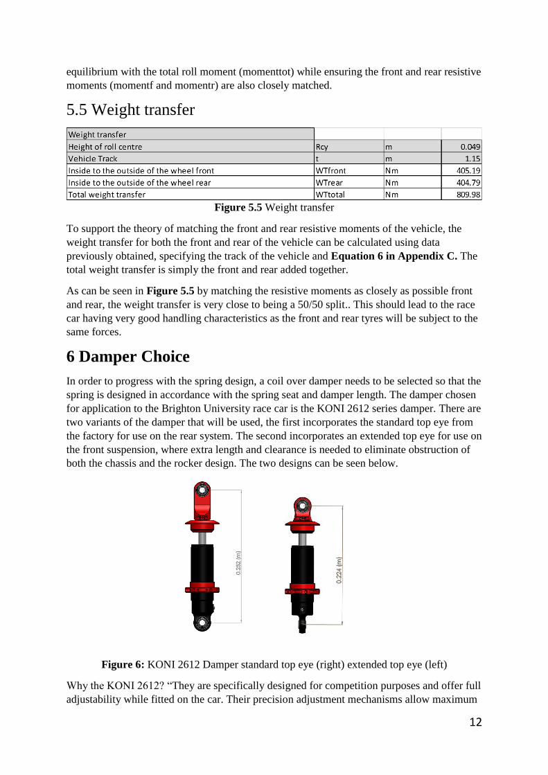
5.5 Weight transfer
Figure 5.5 Weight transfer
To support the theory of matching the front and rear resistive moments of the vehicle, the
weight transfer for both the front and rear of the vehicle can be calculated using data
previously obtained, specifying the track of the vehicle and Equation 6 in Appendix C. The
total weight transfer is simply the front and rear added together.
As can be seen in Figure 5.5 by matching the resistive moments as closely as possible front
and rear, the weight transfer is very close to being a 50/50 split.. This should lead to the race
car having very good handling characteristics as the front and rear tyres will be subject to the
same forces.
6 Damper Choice
In order to progress with the spring design, a coil over damper needs to be selected so that the
spring is designed in accordance with the spring seat and damper length. The damper chosen
for application to the Brighton University race car is the KONI 2612 series damper. There are
two variants of the damper that will be used, the first incorporates the standard top eye from
the factory for use on the rear system. The second incorporates an extended top eye for use on
the front suspension, where extra length and clearance is needed to eliminate obstruction of
both the chassis and the rocker design. The two designs can be seen below.
Figure 6: KONI 2612 Damper standard top eye (right) extended top eye (left)
Why the KONI 2612? “They are specifically designed for competition purposes and offer full
adjustability while fitted on the car. Their precision adjustment mechanisms allow maximum

13
control over the damping forces generated, especially in the low speed damping range.”
(Koni.de, 2015).
The KONI 2612 series damper has been used extensively within formula student with many
of the successful teams incorporating them into their designs. Some of the main advantages
are as follows:
Gas filled monotube design – “Mono tube dampers use a single outer tube. The oil
and nitrogen gas inside are separated by a free piston. Mono tube dampers use much
higher gas pressure than twin tube dampers to better stabilise the oil inside under
extreme usage. The advantages of the mono tube design are larger internal parts,
which mean greater damping force, increased oil capacity, improved heat dissipation,
and the ability to function when inverted” (MeisterR High Performance Suspension &
Coilovers, 2015)
High level of adjustability – The dampers are adjustable in both ‘bump’ and ‘rebound’ states,
this allows fine tuning of handling characteristics by being able to control the generated
damping force in both states.
Lightweight design – The main body, adjustment discs and eyes are all made from cast
aluminium this ensures overall weight is kept to a minimum at just over a kilogram per
damper.
Stroke – The chosen damper has a total stoke of 59mm (29.5mm bump and 29.5mm rebound)
which is the ideal size for the application to this vehicle and conforms to the FSAE rule
T6.1.1 previously mentioned in Chapter 2.2.
The dimensions of the height adjustable spring seat will give the required measurements for the spring
design and can be seen below:
Figure 6.1 height adjustable spring seat dimensions
The large dimension shown above is the outer diamteter of the spring seat, this gives the maximum
value for the coil diameter of the spring. The smaller dimension shows the distance between the inner
section of adjuster and the outer diameter, this specifies the maximum gauge width of the spring wire.
The minimum pressure (Pmin) at which the damper needs to be filled with the nitrogen gas is
calculated using Equation 7 in appendix C, the figure for the area of the piston (Apiston)
minus the area of the of the rod (Arod) is supplied by KONI in the technical manual for the
2612 damper (KONI.com) as 0.869x10⁻³ m2. The maximum bump force is the lateral force
(mu W) previously calculated in Chapter 5.2. The minimum pressure needed, is calculated to
be 2.77N/m2.

14
7 Spring design
Figure 7 Spring geometry
Now that the spring stiffness (Ks) has been found for both the front and rear suspension
(Chapter 5.4) and the maximum coil and wire gauge diamter has been found (Chapter 6),
the rest of the spring can be designed by rearranging the general spring stiffness equation
below, to make the number of active windings (N) the subject.
𝐾𝑠 =𝑑4×𝐺
8×𝑁×𝐷3 - General spring stiffness equation
𝑁 =𝑑4×𝐺
8×𝐷3×𝐾𝑠 – Rearranged to make the number of active windings (N) the subject
The diameters of the coil and gauge of the wire seen above in Figure 7 are slightly smaller
than the spring seat size and maximum wire diameter specified in Figure 6.1 in Chapter 6.
This is so there is room for the spring to fit in the seat without force but tight enough so that it
cannot move enough to cause concern.
The number of active windings is equal to the total windings minus the number of windings
that don’t contribute to the load bearing properties of the spring. In this case, the number of
active windings is equal to the total, as each winding will be used to support the load.
The total height of the spring top to bottom remains the same front and rear as the there is
plenty of room to accommodate the 29mm compression needed without the coils binding, this
conforms to rule T6.1.1 set by the FSAE previously mentioned in Chapter 2.2.
The chosen material for the spring is AISI 304 steel. The reason for this choice is the
relatively low shear modulus in comparison to other steels. This is needed to reduce the
spring windings to an amount that can fit the damper with enough room for compression
without binding together.
Renders of the complete spring and damper assemblies can be seen below and drawings of
the springs can be seen in Appendix E, Figures E1 and E2.
Figure 7.1 Render of the front spring and damper (right) and
the rear spring and damper (left)

15
8 Front spring, damper and anti-roll system design
The front system is divided into two sub-systems. The first system is the ‘bump’ system that
includes a pull rod design incorporating a rod, rocker and the coil-over spring/damper unit.
The second system is the anti-roll system that uses the motion of the rocker to apply a
torsional force through a bar via a set of linkages and levers, supplying an opposing moment
to the opposite wheel during a roll situation to keep the vehicle as flat as possible during
cornering.
8.1 Working principle
During a ‘bump’ scenario when both wheels are deflected in the same manner, for example,
on a straight piece of track with a hump, the push rods act on the rocker attached to the
chassis equally. This results in both coil-over damper units being compressed equally. With a
mirrored movement of the rockers on both sides of the vehicle, the anti-roll bar levers are
moved in the same direction also, resulting in no torsional moment being applied to the anti-
roll bar itself. A working diagram of this principle can be seen in Appendix F, Figure F1.
During a ‘roll’ scenario when weight is transferred to a side of the vehicle, for example,
during cornering, the body of the vehicle rolls towards the outside of the bend, the outer
wheel will move into a ‘bump’ state in respect to the chassis, the inner wheel on the other
hand moves into a droop state and is partially unloaded. With both rockers being rotated in
the opposite direction this results in the levers attached to the anti-roll bar acting in the
opposite direction, this applies a torsional, opposing moment that tries to keep the body of the
vehicle level during cornering. A working diagram of this principle can be seen in Appendix
F, Figure F2.
8.2 Final design overview
Figure 8.1 Front spring, damper and anti-roll system final design

16
Figure 8.2 Front spring, damper ant anti-roll parts list
The two sub systems will be explained individually starting with the front bump system
labelled 1-6 in Figures 8.1 and 8.2. The anti-roll system will be explained after, labelled 7-9
in Figures 8.1 and 8.2
8.3 Bump motion ratio
Pull rod motion ratio
Figure 8.3 Motion ratio of the pull rods to wheel movement
When designing a pull rod system such as the one shown in Figure 8.1, the motion ratio of
the rod movement to wheel movement needs to be found. The movement is not equal due to
the angle at which the rod is mounted (theta) and also the distance at which it is mounted (A)
from the total moving distance (B) in-between the chassis and the upright mount. A working
drawing of the dimensions listed in Figure 8.3 can be found in Appendix F, Figure F1. The
equation used to find the ratio can be found in Appendix C, Equation 8.
The reason for the rod being angled in the position seen, is so that it is perpendicular to the
lower chassis tube, this is crucial, as in order to retain the correct ratios amongst the system
they must be designed on a single axis plane so not to add additional angles that will affect
the overall ratio, this therefore means that the pull rod must be angled towards the centre of
the lower chassis tube, as such that the rocker can be mounted with ease from both sides of
the tube.

17
The next step is to acquire the rocker dimensions needed to amplify the 0.41/1 ratio supplied
by the push rods back to a 1/1 ratio. This is needed to support the previous kinematics
calculations and also supply the correct damper movement and velocities for optimum
performance.
Rocker and final motion ratio
Figure 8.4 Motion ratio of the rockers and final motion ratio
Now that the motion ratio of the pull rods has been found, the rocker co-ordinates need to be
designed in such a way that the final motion ratio is 1/1. This is not the only concern, as the
rocker needs to be designed in such a way that the arm connected to the coil-over unit (A) is
situated high enough to clear the lower wishbone when mounted. With a wishbone deflection
of 3 degrees (target roll angle) in either bump or droop and an arm length of 0.14m (A), there
is enough clearance plus a safety margin of an extra 1 degree. By tweaking the distance (B)
and angle (Theta) of the pull rod connection arm on the rocker and using the goal seek
function in excel, the final motion ratio, which is the motion ratio of the pull rods multiplied
by the rocker motion ratio, can be found and altered to meet the 1/1 (Front 1) ratio needed.
The dimensions can then be checked against the chassis to see if they are suitable and if there
is enough clearance for movement. The dimensions found in Figure 8.4 meet these
requirements and there is enough room for the rocker to rotate with the 0.012 linear rod
movement. A working drawing can be found in Appendix F, Figure F4. The equation used
to calculate the motion ratio of the rockers is the same used to find the motion ratio of the
pull rods substituting the relevant dimensions above.
As an addition to the chosen 1/1 ratio design, there are also rocker dimensions above (Front 2
and Front 3) that are also safe to use on the chassis but supply a lower and higher variant
motion ratio. These could be used for reducing or increasing the amount that the spring and
damper are compressed in comparison to wheel travel. A scenario where this would be useful
is if the spring geometry changes to a point where a smaller compression is needed to stop the
coils binding, this may happen in the event of the springs changing for a softer variant with
more coils on a severely wet day, where a low friction coefficient is apparent. The rockers
can be designed and manufactured separately and swapped in and out by the 4 mounting
points used on them in a short amount of time.
18
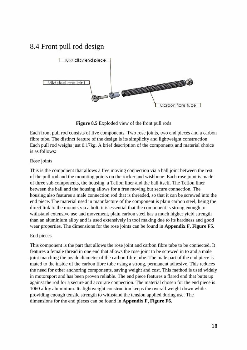
8.4 Front pull rod design
Figure 8.5 Exploded view of the front pull rods
Each front pull rod consists of five components. Two rose joints, two end pieces and a carbon
fibre tube. The distinct feature of the design is its simplicity and lightweight construction.
Each pull rod weighs just 0.17kg. A brief description of the components and material choice
is as follows:
Rose joints
This is the component that allows a free moving connection via a ball joint between the rest
of the pull rod and the mounting points on the rocker and wishbone. Each rose joint is made
of three sub components, the housing, a Teflon liner and the ball itself. The Teflon liner
between the ball and the housing allows for a free moving but secure connection. The
housing also features a male connection rod that is threaded, so that it can be screwed into the
end piece. The material used in manufacture of the component is plain carbon steel, being the
direct link to the mounts via a bolt, it is essential that the component is strong enough to
withstand extensive use and movement, plain carbon steel has a much higher yield strength
than an aluminium alloy and is used extensively in tool making due to its hardness and good
wear properties. The dimensions for the rose joints can be found in Appendix F, Figure F5.
End pieces
This component is the part that allows the rose joint and carbon fibre tube to be connected. It
features a female thread in one end that allows the rose joint to be screwed in to and a male
joint matching the inside diameter of the carbon fibre tube. The male part of the end piece is
mated to the inside of the carbon fibre tube using a strong, permanent adhesive. This reduces
the need for other anchoring components, saving weight and cost. This method is used widely
in motorsport and has been proven reliable. The end piece features a flared end that butts up
against the rod for a secure and accurate connection. The material chosen for the end piece is
1060 alloy aluminium. Its lightweight construction keeps the overall weight down while
providing enough tensile strength to withstand the tension applied during use. The
dimensions for the end pieces can be found in Appendix F, Figure F6.
19
Carbon fibre tubes
Being the main structure, and largest component in the assembly, it is essential that the
material chosen for the rod is both strong and lightweight. The carbon fibre tube has a
Young’s modulus of 90Gpa, if compared to plain carbon steel that has a Young’s modulus of
210GPa this seems relatively low, with the forces being applied through the tube, this is more
than acceptable. Stress analysis of the tubes will be explained further in the report when the
rear design is explained, this is because the rear tubes are under compression due to the push
rod configuration so are susceptible to higher stress, the same diameter tube will be used front
and rear so it is only necessary to stress test the rear rods. The main advantage of the carbon
fibre tubes is the weight, the tube itself only weighs 0.05kg, if a plain carbon steel tube of the
same dimensions was used it would weigh 0.21kg, this reduction in unsprung weight will
increase handling performance and increase the power to weight ratio of the race car. The
dimensions of the Front carbon fibre tubes can be found in Appendix F, Figure F7. The pull
rod assembly can be seen in Figure F8.
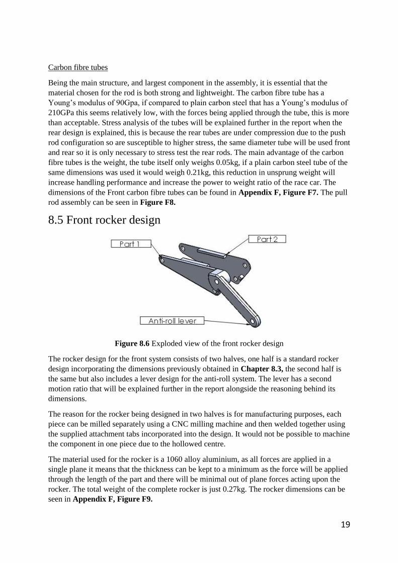
8.5 Front rocker design
Figure 8.6 Exploded view of the front rocker design
The rocker design for the front system consists of two halves, one half is a standard rocker
design incorporating the dimensions previously obtained in Chapter 8.3, the second half is
the same but also includes a lever design for the anti-roll system. The lever has a second
motion ratio that will be explained further in the report alongside the reasoning behind its
dimensions.
The reason for the rocker being designed in two halves is for manufacturing purposes, each
piece can be milled separately using a CNC milling machine and then welded together using
the supplied attachment tabs incorporated into the design. It would not be possible to machine
the component in one piece due to the hollowed centre.
The material used for the rocker is a 1060 alloy aluminium, as all forces are applied in a
single plane it means that the thickness can be kept to a minimum as the force will be applied
through the length of the part and there will be minimal out of plane forces acting upon the
rocker. The total weight of the complete rocker is just 0.27kg. The rocker dimensions can be
seen in Appendix F, Figure F9.

20
8.6 Anti-roll system design
Figure 8.7 Anti-roll bar properties
The anti-roll system consists of four main components. The rocker, the anti-roll bar rods, the
levers and the anti-roll bar itself. The anti-roll bar is supported between the chassis tubes on
the vehicle using bearings and bearing holders, this allows for free torsional movement of the
bar and good support. The system functions using the rotational movement of the rocker
lever, which is then transferred into a linear motion using the anti-roll bar rods and then back
into a rotational movement via the anti-roll levers to apply a torsional moment to the anti-roll
bar itself.
To be able to calculate the anti-roll bar diameter, the angle of twist (ARB twist) at maximum
wheel travel needs to be found. This depends entirely on the motion ratio of the rocker lever.
Using the same theory and calculations previously used in Chapter 8.4, with the exception of
angle theta as there is no angle to be accounted for, this can be done with ease based on the
dimensions of the lever. The dimensions of the lever were found by examining the best way
in which to package the system so that the lever is orientated around the chassis tube and long
enough to have enough room for movement without obstruction. These can be seen in
Appendix F, Figure F10. The motion ratio of the rocker lever can be seen below in Figure
8.8.
Figure 8.8 Motion ratio of the rocker lever
By observing the results it can be seen that with 0.029m of wheel travel there will be 0.034m
of linear travel transmitted to the roll bar rods. By observing the dimensions of the anti-roll
bar levers this linear movement can be used to calculate how much twist will be applied to
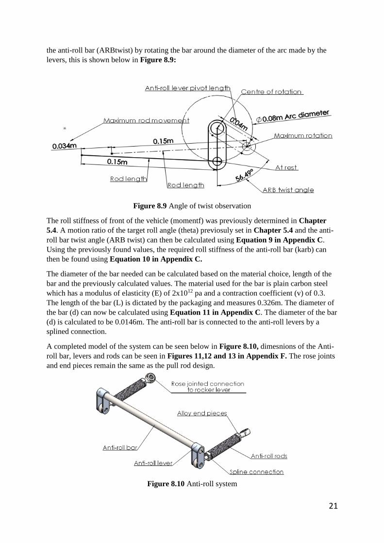
21
the anti-roll bar (ARBtwist) by rotating the bar around the diameter of the arc made by the
levers, this is shown below in Figure 8.9:
Figure 8.9 Angle of twist observation
The roll stiffness of front of the vehicle (momentf) was previously determined in Chapter
5.4. A motion ratio of the target roll angle (theta) previosuly set in Chapter 5.4 and the anti-
roll bar twist angle (ARB twist) can then be calculated using Equation 9 in Appendix C.
Using the previously found values, the required roll stiffness of the anti-roll bar (karb) can
then be found using Equation 10 in Appendix C.
The diameter of the bar needed can be calculated based on the material choice, length of the
bar and the previously calculated values. The material used for the bar is plain carbon steel
which has a modulus of elasticity (E) of 2x10¹² pa and a contraction coefficient (v) of 0.3.
The length of the bar (L) is dictated by the packaging and measures 0.326m. The diameter of
the bar (d) can now be calculated using Equation 11 in Appendix C. The diameter of the bar
(d) is calculated to be 0.0146m. The anti-roll bar is connected to the anti-roll levers by a
splined connection.
A completed model of the system can be seen below in Figure 8.10, dimesnions of the Anti-
roll bar, levers and rods can be seen in Figures 11,12 and 13 in Appendix F. The rose joints
and end pieces remain the same as the pull rod design.
Figure 8.10 Anti-roll system

22
9 Rear spring and damper system design
Unlike the front system the rear system incorporates a ‘bump’ only system. The reason for
the rear system not containing an anti-roll solution is due to it not being needed. When
forces are applied to the vehicle during a cornering scenario they tend to be under breaking
conditions where an extra roll stiffness is needed to counteract the extra force of weight
being distributed towards the front of the vehicle. During this same scenario the rear
suspension becomes partially unloaded eliminating the need for extra stiffness to be
applied. By not incorporating an anti-roll system to the rear of the vehicle also has other
advantages such as; weight reduction, more room for vital drivetrain components to be
accessed and an increase in reliability with less moving parts susceptible to failure.
9.1 Design overview
Figure 9.1 Rear design render
Figure 9.2 Rear spring and damper system parts list The rear system uses a push rod design opposed to the pull rod design used on the front of the
vehicle, the working principle remains the same except the rocker is actuated in a pushing
motion rather than a pulling motion.

23
9.2 Bump motion ratio
Pull rod motion ratio
Figure 9.2 Motion ratio dimensions of the push rods
Just like the front system, the motion ratio of the push rods needs to be found in relation to
wheel travel. Instead of the ratio being taken from the top wishbone like the front system, it is
taken from the lower wishbone as this is where the pushing movement is supplied from and
the rod is attached to. A working drawing of the dimensions listed in Figure 9.2 can be seen
in Appendix F, Figure F14. Much the same as the front system the angle of the push rods is
dictated by packaging constraints and the rocker mounting location.
The next step is to acquire the pivot dimensions for the rocker to regain the 1/1 ratio lost with
the push rod dimensions.
Rocker and final motion ratio
Figure 9.3 Motion ratio dimensions of the rocker
Much the same as the front system the rear rocker had to be designed to regain the 1/1 ratio
needed for the kinematics calculations. The rocker chassis pivot and damper connection had
to also be situated above each other so that the damper orientation is correct for mounting the
to the central rear chassis bar. This led to an acute angle (Theta) and long rocker arms (A, B)
being needed to package the system correctly. Using the same process as the front system, the
rear rocker dimensions are tweaked in excel using the goal seek function as an aid until a 1/1
ratio is achieved. The dimensions were continuously checked against the chassis making sure
that with a maximum rod movement of 0.022m the rocker and rod remained operational and
no contact is made with the rest of the chassis components. A working drawing of the
dimensions listed in Figure 9.3 can be seen in Appendix F, Figure F15.
24
9.3 Rear push rod design
The rear push rods are designed in the same way as the front rods using the same end pieces
and rose joints. Due to the rod being under compression it is essential that the carbon tubes
are strong enough to handle the bump force acting on them during use. This force was
previously calculated as the lateral force (Flateral) of the vehicle during cornering. As the
rods are under compression they are subject to failing more than the front rods which are
under tension. For this reason it is only essential to test the rear tubes.
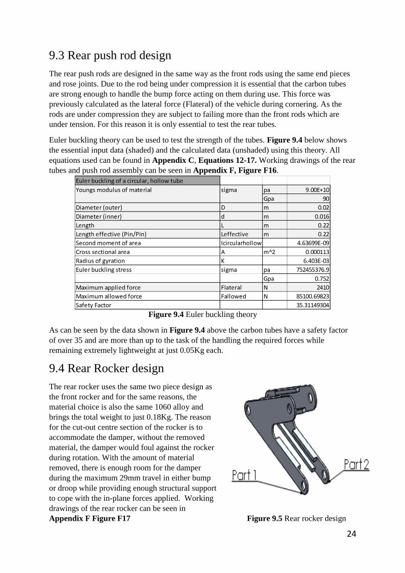
Euler buckling theory can be used to test the strength of the tubes. Figure 9.4 below shows
the essential input data (shaded) and the calculated data (unshaded) using this theory. All
equations used can be found in Appendix C, Equations 12-17. Working drawings of the rear
tubes and push rod assembly can be seen in Appendix F, Figure F16.
Figure 9.4 Euler buckling theory
As can be seen by the data shown in Figure 9.4 above the carbon tubes have a safety factor
of over 35 and are more than up to the task of the handling the required forces while
remaining extremely lightweight at just 0.05Kg each.
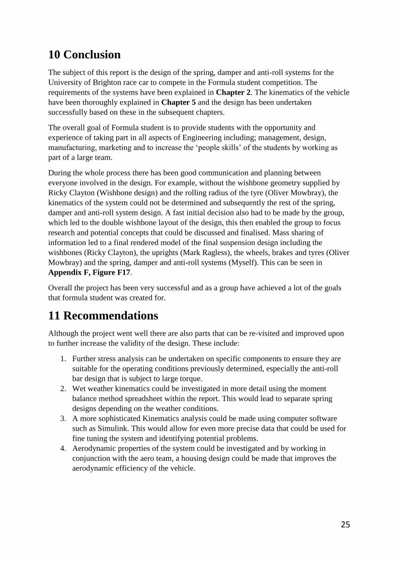
9.4 Rear Rocker design
The rear rocker uses the same two piece design as
the front rocker and for the same reasons, the
material choice is also the same 1060 alloy and
brings the total weight to just 0.18Kg. The reason
for the cut-out centre section of the rocker is to
accommodate the damper, without the removed
material, the damper would foul against the rocker
during rotation. With the amount of material
removed, there is enough room for the damper
during the maximum 29mm travel in either bump
or droop while providing enough structural support
to cope with the in-plane forces applied. Working
drawings of the rear rocker can be seen in
Appendix F Figure F17 Figure 9.5 Rear rocker design
25
10 Conclusion
The subject of this report is the design of the spring, damper and anti-roll systems for the
University of Brighton race car to compete in the Formula student competition. The
requirements of the systems have been explained in Chapter 2. The kinematics of the vehicle
have been thoroughly explained in Chapter 5 and the design has been undertaken
successfully based on these in the subsequent chapters.
The overall goal of Formula student is to provide students with the opportunity and
experience of taking part in all aspects of Engineering including; management, design,
manufacturing, marketing and to increase the ‘people skills’ of the students by working as
part of a large team.
During the whole process there has been good communication and planning between
everyone involved in the design. For example, without the wishbone geometry supplied by
Ricky Clayton (Wishbone design) and the rolling radius of the tyre (Oliver Mowbray), the
kinematics of the system could not be determined and subsequently the rest of the spring,
damper and anti-roll system design. A fast initial decision also had to be made by the group,
which led to the double wishbone layout of the design, this then enabled the group to focus
research and potential concepts that could be discussed and finalised. Mass sharing of
information led to a final rendered model of the final suspension design including the
wishbones (Ricky Clayton), the uprights (Mark Ragless), the wheels, brakes and tyres (Oliver
Mowbray) and the spring, damper and anti-roll systems (Myself). This can be seen in
Appendix F, Figure F17.
Overall the project has been very successful and as a group have achieved a lot of the goals
that formula student was created for.
11 Recommendations
Although the project went well there are also parts that can be re-visited and improved upon
to further increase the validity of the design. These include:
1. Further stress analysis can be undertaken on specific components to ensure they are
suitable for the operating conditions previously determined, especially the anti-roll
bar design that is subject to large torque.
2. Wet weather kinematics could be investigated in more detail using the moment
balance method spreadsheet within the report. This would lead to separate spring
designs depending on the weather conditions.
3. A more sophisticated Kinematics analysis could be made using computer software
such as Simulink. This would allow for even more precise data that could be used for
fine tuning the system and identifying potential problems.
4. Aerodynamic properties of the system could be investigated and by working in
conjunction with the aero team, a housing design could be made that improves the
aerodynamic efficiency of the vehicle.
26
References
2015 Formula SAE rules. (2015). 1st ed. [ebook] FSAE, p.57. Available at:
http://students.sae.org/cds/formulaseries/rules/2015-16_fsae_rules.pdf [Accessed 31 Mar.
2015].
Btcc technical, (2015). Push rod suspension. [image] Available at:
https://btcctechnical.wordpress.com/ [Accessed 31 Mar. 2015].
Car Bibles, (2015). Anti-roll bar. [image] Available at:
http://www.carbibles.com/suspension_bible_pg4.html#antiroll [Accessed 1 Apr. 2015].
Car Bibles, (2015). Double Wishbone. [image] Available at:
http://www.carbibles.com/suspension_bible.html [Accessed 31 Mar. 2015].
Coren, D. (2015). Chassis Kinematics. 1st ed. [ebook] p.38. Available at:
https://studentcentral.brighton.ac.uk/bbcswebdav/pid-2331131-dt-content-rid-
4497627_1/courses/ME341_SEM1_2014/Session%204%20Chassis%20Kinematics%20SC.p
df [Accessed 7 Apr. 2015].
F1 Fanatic, (2015). Pull rod suspension. [image] Available at:
http://www.f1fanatic.co.uk/2012/03/28/ferraris-front-pullrod-suspension/ [Accessed 31 Mar.
2015].
Jones, E. and Childers, R. (1994). Contemporary college physics. Reading, Mass. [u.a.]:
Addison-Wesley.
Koni.de, (2015). KONI: 2612 series. [online] Available at:
http://www.koni.de/pkw/racing/2612-series/ [Accessed 8 Apr. 2015].
MeisterR High Performance Suspension & Coilovers, (2015). Suspension Basics - MeisterR
High Performance Suspension & Coilovers. [online] Available at:
http://www.meisterr.co.uk/technical/suspension-basics/ [Accessed 8 Apr. 2015].
Racecar Engineering, (2015). TU Delft DUT-14. [image] Available at: http://www.racecar-
engineering.com/cars/delft-4/ [Accessed 31 Mar. 2015].
ScarbsF1, (2015). Rocker Ant-roll solution. [image] Available at:
http://scarbsf1.com/blog1/2011/10/26/front-anti-roll-bar-solutions/ [Accessed 1 Apr. 2015].
Victorylibrary.com, (2015). Sprung Vs. Unsprung Chassis Weight: Definition and Examples.
[online] Available at: http://victorylibrary.com/mopar/sprung-c.htm [Accessed 7 Apr. 2015].

27
Appendix A – Decision matrix Criteria
Decision matrix criteria and weightings
Weight (per axle)
The weight of vehicle components is crucial. By reducing overall vehicle weight will increase
performance based on power to weight ratio as well as handling capabilities. For suspension
components, weight can vary between 5Kg per axle, based on a very simple design, to over
20kg per axle for a complicated design. Therefore I have chosen the three weightings below
to suit this.
1. >15Kg
2. <15Kg
3. <10Kg
For the overall criteria weighting I have chosen 3, this is because weight plays a big part in a
formula student vehicle.
Centre of gravity
The centre of gravity of a vehicle is important to retain good handling. By reducing the centre
of gravity allows for less weight to be transferred into a roll moment when cornering, braking
or accelerating. For suspension components the effect on the centre of gravity depends on
where they are mounted on a vehicle, if they are mounted ‘high’ in the vehicle then this will
increase the height of the centre of gravity and if they are mounted ‘low’ it will reduce the
height of the centre of gravity. Therefore I have chosen the three weightings below to suit
this.
1. High
2. Middle
3. Low
For the overall criteria weighting I have chosen a 2, this is because the centre of gravity plays
a big part in where the weight is distributed around the vehicle and can have a serious effect
on handling capabilities.
Chassis compatibility (Packaging)
The chassis we have supplied has existing mounting points for suspension components. This
is a proven design that has already undergone extensive testing to find good solutions.
Redesigning the suspension system will require adjustment to the chassis in order to fit
components. This is an important criteria as the chassis is complete and modifying it may
compromise other areas of the design. Therefore I have chosen the three weightings below to
suit?
1. Extensive adjustment needed
2. Minor adjustment needed
3. No adjustment needed

28
For the overall criteria weighting I have chosen a 1, this is because the chassis can be
adjusted to suit any of the suspension systems. Although compatibility is important, this
criteria is mainly based on time and ease of fitting.
Adjustability
Being able to adjust the system is crucial. The handling characteristics can be fine-tuned to a
higher tolerance with more adjustability, leading to an overall better performance of the
vehicle. Some systems offer more adjustability than others. Therefore I have chosen the three
weightings below to suit this.
1. Low
2. Medium
3. Extensive
For the overall criteria weighting I have chosen a 3, this is because adjustability is very
important for fine tuning the vehicle to a given scenario and can be the difference between
the vehicle performing well or not.
Exposed surface area (Aerodynamics)
Size of the components can have an impact on such things as aerodynamics, by reducing the
size of the components will reduce the surface area in which the air passes over them. Size
can also have an effect on how the parts are fitted to the vehicle and chassis compatibility.
Although vague, the weightings I have selected below give a rough idea on this.
1. Large
2. Medium
3. Small
For the overall criteria weighting I have chosen 1, this is because weight will have an almost
direct impact on size. For such things as aerodynamics the impact will be small overall.
Previously successful design within formula student
When deciding on a system, looking at previously successful designs within formula student
is very helpful. Research has already been made by other teams into the designs and there are
reasons as to why they have been chosen. The weightings I have selected below will reflect
this.
1. No previous use
2. Have been used to some success
3. Widely used and successful
For the overall criteria weighting I have chosen a 2, this is because previously successful designs
should not be overlooked and should influence the decision to some extent

29
Appendix B – Roll axis definition
Front roll centre height
Figure B1
The above drawing shows the height of the front roll centre. Based on the location of the instantaneous centre, the vehicle centreline and the
contact patch of the tyre. As both sides of the vehicle are symmetrical there is only the need to reference one side. All dimensions are given in
metres and are supplied by Ricky Clayton (wishbone design)

30
Rear roll centre height
Figure B2
The above drawing shows the height of the Rear roll centre. Based on the location of the instantaneous centre, the vehicle centreline and the
contact patch of the tyre. As both sides of the vehicle are symmetrical there is only the need to reference one side. All dimensions are given in
metres and are supplied by Ricky Clayton (wishbone design)

31
Height of centre of mass
Figure B3
To find an approximate value for the height of centre of mass, we can presume that the distribution of mass in the y axis will be central to the
main body of the chassis. Therefore taking the simple measurements seen above in Figure B3, the height of the centre of mass can be found as
0.338 metres. All measurements are given in metres.

32
Vehicle Weight distribution and Centre of gravity
Figure B4
The above diagram and table show the distribution of weight within the vehicle and the length fraction of the centre of gravity. All component
weights are approximated based on researched averages.
Weight distribution and Centre of gravity
no Item Mass (kg) Mass (N) x (m)
1 Driver and seat 65 637.65 1.45
2 Engine 50 490.5 1.78
3 Chassis 50 490.5 1.35
4 Fuel tank 15 147.15 1.88
5 Front hub assemblies (including wheels) 15 147.15 0.88
6 Rear hub assemblies (including wheels) 15 147.15 2.36
7 Steering components 15 147.15 0.82
8 Differential 10 98.1 2.19
9 Driveshafts (pair) 10 98.1 2.27
10 Gearbox 8 78.48 1.78
11 Body panels and aero 7 68.67 1.35
12 Exhaust components 5 49.05 2
13 Front suspension 4 39.24 0.88
14 Rear suspension 4 39.24 2.27
Total 273 2678.13
Longitudinal length of the centre of gravity(m) 1.58
Overall length(m) 2.59
Length fraction of centre of gravity 0.61

33
Longitudinal distance between centre of mass and vehicle length
Figure B5
The above drawing, Figure B5, shows the longitudinal distances between the centre of mass and the front and rear of the race car, this will be
used to determine how the weight is distributed around the vehicle kinematically.
34
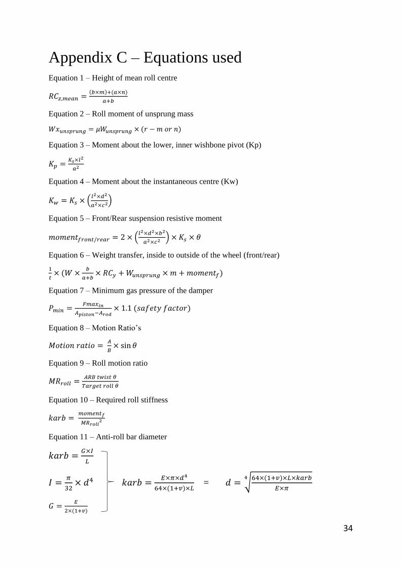
Appendix C – Equations used Equation 1 – Height of mean roll centre
𝑅𝐶𝑧,𝑚𝑒𝑎𝑛 =(𝑏×𝑚)+(𝑎×𝑛)
𝑎+𝑏
Equation 2 – Roll moment of unsprung mass
𝑊𝑥𝑢𝑛𝑠𝑝𝑟𝑢𝑛𝑔 = 𝜇𝑊𝑢𝑛𝑠𝑝𝑟𝑢𝑛𝑔 × (𝑟 − 𝑚 𝑜𝑟 𝑛)
Equation 3 – Moment about the lower, inner wishbone pivot (Kp)
𝐾𝑝 =𝐾𝑠×𝑙2
𝑎2
Equation 4 – Moment about the instantaneous centre (Kw)
𝐾𝑤 = 𝐾𝑠 × (𝑙2×𝑑2
𝑎2×𝑐2)
Equation 5 – Front/Rear suspension resistive moment
𝑚𝑜𝑚𝑒𝑛𝑡𝑓𝑟𝑜𝑛𝑡/𝑟𝑒𝑎𝑟 = 2 × (𝑙2×𝑑2×𝑏2
𝑎2×𝑐2 ) × 𝐾𝑠 × 𝜃
Equation 6 – Weight transfer, inside to outside of the wheel (front/rear)
1
𝑡× (𝑊 ×
𝑏
𝑎+𝑏× 𝑅𝐶𝑦 + 𝑊𝑢𝑛𝑠𝑝𝑟𝑢𝑛𝑔 × 𝑚 + 𝑚𝑜𝑚𝑒𝑛𝑡𝑓)
Equation 7 – Minimum gas pressure of the damper
𝑃𝑚𝑖𝑛 =𝐹𝑚𝑎𝑥𝑖𝑛
𝐴𝑝𝑖𝑠𝑡𝑜𝑛−𝐴𝑟𝑜𝑑× 1.1 (𝑠𝑎𝑓𝑒𝑡𝑦 𝑓𝑎𝑐𝑡𝑜𝑟)
Equation 8 – Motion Ratio’s
𝑀𝑜𝑡𝑖𝑜𝑛 𝑟𝑎𝑡𝑖𝑜 = 𝐴
𝐵× sin 𝜃
Equation 9 – Roll motion ratio
𝑀𝑅𝑟𝑜𝑙𝑙 =𝐴𝑅𝐵 𝑡𝑤𝑖𝑠𝑡 𝜃
𝑇𝑎𝑟𝑔𝑒𝑡 𝑟𝑜𝑙𝑙 𝜃
Equation 10 – Required roll stiffness
𝑘𝑎𝑟𝑏 = 𝑚𝑜𝑚𝑒𝑛𝑡𝑓
𝑀𝑅𝑟𝑜𝑙𝑙2
Equation 11 – Anti-roll bar diameter
𝑘𝑎𝑟𝑏 =𝐺×𝐼
𝐿
𝐼 =𝜋
32× 𝑑4 𝑘𝑎𝑟𝑏 =
𝐸×𝜋×𝑑4
64×(1+𝑣)×𝐿 = 𝑑 = √
64×(1+𝑣)×𝐿×𝑘𝑎𝑟𝑏
𝐸×𝜋
4
𝐺 =𝐸
2×(1+𝑣)

35
Equation 12 - Euler second moment of area
𝐼, 𝑐𝑖𝑟𝑐𝑢𝑙𝑎𝑟ℎ𝑜𝑙𝑙𝑜𝑤 = 𝜋×(𝐷4−𝑑4)
64
Equation 13 – Cross sectional area of a hollow tube
𝐴 = (0.25 × 𝜋 × 𝐷2) − (0.25 × 𝜋 × 𝑑2)
Equation 14 – Euler radius of gyration
𝑘 = √𝐼
𝐴
Equation 15 – Euler buckling stress
𝜎 =𝜋2×𝐸
(𝐿
𝑘)2
Equation 16 – Euler maximum allowed force
𝐹𝑎𝑙𝑙𝑜𝑤𝑒𝑑 = 𝜎 × 𝐴
Equation 17 – Safety Factor
𝑆. 𝐹 =𝐹𝑎𝑙𝑙𝑜𝑤𝑒𝑑
𝐹𝑙𝑎𝑡𝑒𝑟𝑎𝑙

36
Appendix D – Resistive Moments
Front resistive rates
Figure D1
The diagram above shows the related dimensions to where the rates are taken for the resistive moments on the front suspension, the rates are also
highlighted by the red arrows and labelled accordingly. All measurements are taken in meters (m).
Kw
Kp, Ks

37
Rear resistive rates
Figure D2
The diagram above shows the related dimensions to where the rates are taken for the resistive moments on the rear suspension, the rates are also
highlighted by the red arrows and labelled accordingly. All measurements are taken in meters (m).
Kw Kp, Ks

38
Appendix E – Spring design
Front spring geometry
Figure E1 Shows
the geometry of the front spring incorporating a 0.0068m wire gauge, a 0.0614m coil
diameter and 7 active windings over a 0.12m height.
Rear spring geometry
Figure E2 Shows the
geometry of the rear spring incorporating a 0.0068m wire gauge, a 0.0614m coil diameter and
6 active windings over a 0.12m height.

39
Appendix F – Final designs Figure F1

40
Figure F2

41
Front pull rod motion ratio
Figure F3 Front pull rod motion ratio dimensions
Front rocker motion ratio
Figure F4 Front rocker motion ratio dimensions

42
Figure F5 Rose joint dimensions
Figure F6 End piece dimensions
Figure F7 Front carbon tube dimensions

43
Figure F8 Complete pull rod assembly
Figure F9 Rocker assembly dimensions
Figure F10 Rocker lever motion ratio

44
Figure F11 Anti-roll bar dimensions
Figure F12 Anti-roll levers dimensions
Figure F13 Anti-roll carbon tube and rod assembly dimensions

45
Figure F14 Push rod motion ratio dimensions
Figure F15 Rear rocker motion ratio dimensions
Figure F16 rear push rod tube and assembly dimensions
46
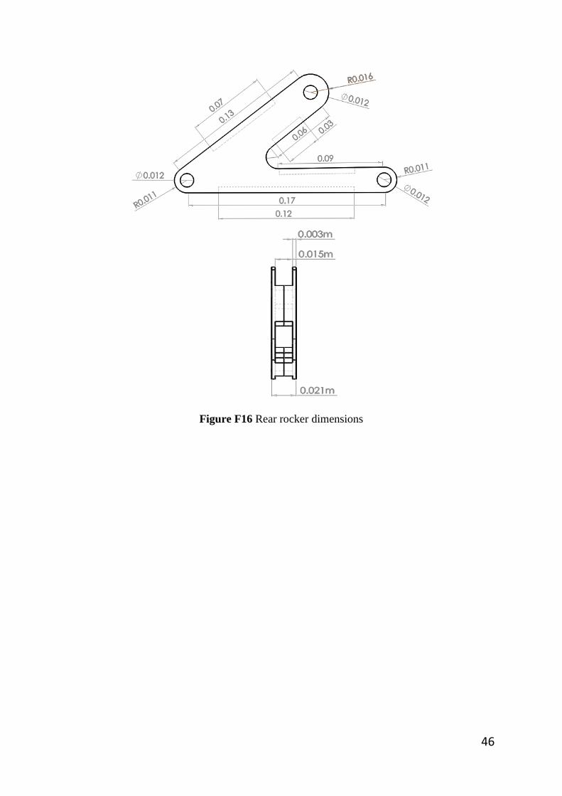
Figure F16 Rear rocker dimensions

47
Figure F17 Final rendered group design