dissolution of solids and pressure drop in a cyclone semibatch reactor and a two impinging streams...
TRANSCRIPT

1930 Ind. Eng. Chem. Res. 1988, 27, 1930-1936
Dissolution of Solids and Pressure Drop in a Cyclone Semibatch Reactor and a Two Impinging Streams Semibatch Reactor
Abraham Tamir* and Omri Falk Department of Chemical Engineering, Ben Gurion University of the Negeu, Beer Sheua, Israel
A semibatch reactor, operated as a cyclone or as a two impinging streams (TIS) device, was employed for studying the effect of the following design parameters on the dissolution mass transfer of solid particles: the holdup of the particles, the diameter of the particles, and the water flow rate in which chemicals (e.g., urea, sodium nitrate, and sodium nitrite) were dissolved. In addition, the hydro- dynamic behavior of the reactors was investigated. Correlations, based on dimensionless analysis, were developed, relating mass-transfer coefficients and pressure drop on the reactor t o operating Darameters. The cyclone reactor gave the highest mass-transfer coefficients when compared with
0 1988 American Chemical Society
the TIS reactor and other commonly used
The essence of the method of impinging streams, first suggested by Elperin (1961) in the 19609, is that two coaxial countercurrent streams of gas-particle suspensions flow out from closely placed pipelines and are brought into imp- ingement. A t the impingement zone, heat- and mass- transfer rates are intensified due to the following effects: (a) significant increase of the relative velocity between the phases, (b) increase of the particles’ residence time due to their oscillatory motion, and (c) turbulent mixing caused by jet impingement.
Tamir and Grinholtz (1987) investigated the perform- ance of a continuous solid-liquid two impinging streams (TIS) reactor. I t was found that the TIS reactor is a very effective device for dissolving urea particles in water, and it provides relatively higher mass-transfer coefficients than other reactors designed for continuous operation. How- ever, because of technical limitations in the case of the continuous reactor, it was impossible to systematically investigate the effects of important design parameters (such as water and particle flow rates; size and chemical nature of the particles) on the dissolution mass-transfer coefficient. Therefore, the major objectives of the present research were (a) to study the effects of chemical nature of the substances (urea, sodium nitrate, sodium nitrite), particle size, holdup, and water flow rate on the dissolution rate of solids in water; (b) to study the hydrodynamic behavior of the TIS reactor; (c) to compare the perform- ance of the TIS to the cyclone configurations with respect to mass transfer and the energy needed to transfer the solid-liquid suspensions through the reactors (it should be noted that the TIS reactor can be converted very easily into the cyclone configuration, as explained below); and, (d) to develop correlations, which are essential for engi- neering design, relating mass-transfer and hydrodynamic quantities with the relevant parameters.
The semibatch TIS reactor as well as the cyclone device were employed in the study. The water was in continuous flow and the solid particles were introduced into the re- actor in the form of a pulse input.
I t is noteworthy that the present work complements previous investigations in the field of transfer processes in impinging streams such as drying (Tamir et al., 1984; Kitron et al., 1987), mixing of solids and gases (Tamir and Luzzatto, 1985a,b; Kitron et al., 1987), absorption and desorption of gases in liquids (Tamir and Herskowitz, 1985; Tamir, 1986; Herskowitz, et al., 1987), preparation of emulsions (Tamir and Sobhi, 1985), dissolution of solids (Tamir and Grinholtz, 1987), and combustion (Ziv et al.,
*To whom correspondence should be addressed.
0888-5885 f 88/2621-193O$Q1.50/0
devices for dissolution of solids.
1988). Various configurations of impinging streams re- actors have also been explored such as the four impinging streams and multistage reactors (Kitron et al., 1987). The effect of the properties of the solid particles on the hy- drodynamics was also investigated (Tamir et al., 1985), as well as the residence time distribution of the particles (Luzzatto et al., 1984; Tamir and Kitron, 1987) and scale-up rules for TIS reactors (Tamir and Shalmon, 1988). The results of the above investigations were very useful in convincing the potential user of the effectiveness of the method of impinging streams in performing technological processes, and a review of the subject by Tamir and Kitron (1987) is available.
The Semibatch Two Impinging Streams and Cyclone Reactors
The TIS reactor with tangential feed of water is shown schematically in Figure 1. It is comprised of the following elements: a cylindrical reactor (1) made of perspex and two water inlet pipes (2) with diameters of 0.01 m. Very thin screens (3) are placed in the reactor in order to pre- vent outflow of particles from the reactor. Particles are introduced as pulse input by means of an injector (4) into the impingement zone of the streams. The bottom of the injector is covered with a plastic sheet (6) which is perfo- rated as the particles are introduced into the reactor. In addition, there are small valves (7) for deaeration of the reactor.
Tap water from a feed vessel, passing through a filter and a rotameter, is continuously pumped into the reactor through plastic pipes (8) of 1-in. diameter. The car- tridge-type filter, manufactured by Hytrex, removes par- ticles of up to 20 wm. An iron element (9) splits the water flow in order to create two impinging streams. Water leaves the reactor through a 3/4-in. gate valve (12). The pressure drop between the inlet and the outlet of the re- actor is measured between points 10 and 11 which are connected to a manometer through valves 10 and 11. Finally, item 13 is a sampling pipe connected to a spec- trophotometer for continuous determination of the solute concentration in water.
The cyclone mode of operating the reactor is obtained by closing one arm of the splitting device (9) and directing the total water flow rate in a tangential flow through the other arm. It should be noted that in both modes the reactor was in a horizontal position, as shown in Figure 1 (water feed pipe (8) at the bottom and injector (4) on top). This has been done in order to minimize gravity effects at low water flow rates because the specific gravity of the particles investigated was higher than unity.

Ind. Eng. Chem. Res., Vol. 27, No. 10, 1988 1931
\ Eu W
Table I. Properties of the Particles kind of particle shape of particle 103dp, mb pp, kg/m3 IO9&,, m/s (Sc) C* (20 "C)
Hydrodynamic Experiments acetal spherical 0.473 1310
red plastic particles rectangular parallelepiped 0.405 1030
urea powder (spherical) 0.148, 0.283 (1.35, 1.76, 2.36) 1335 1.18 (20 "C) (850) 0.515 sodium nitrate powder (spherical) 0.148, 0.283 (1.43, 1.8, 2.45) 2257 0.74 (24 "C) (1350) 0.468 sodium nitrite powder 0.148, 0.283 2168 0.74a (24 O C ) (1350) 0.453
polyethylene cylindrical 0.970 910
Dissolution Experiments
"The diffusivity in water of sodium nitrite is not known. Bearing in mind the similarity to sodium nitrate in the chemical formula, it was assumed that both chemicals possess the same diffusivity in water. bSee Nomenclature for details.
W A T E R -
1: I 1 7 1 I 3 6
0066 - i
WATER F E E D
A11 d imens ions In meters
TOP VIEW AND A - A CROSS-SECTION
W A T E R FEED
Figure 1. Scheme of semibatch TIS (or cyclone) reactor for disso- lution of solid particles.
Pressure Drop on the Reactor The pressure drop (APJ between the inlet and the outlet
of the reactor (points 10 and 11 in Figure 1) was deter- mined as a function of water flow rate, nonsoluble particles type (Table I), and their holdup. In order to express the measurements in a concise form, the following procedure was adopted.
The pressure drop (Uf) on the reactor is assumed to be a function of the following parameters:
(1)
(2)
Eu, = f(Re,) (3 ) and hence
v = E u , / E u , = aPp/aP, = fW,, v, PJP,, d J d ) (4)
It has been found that these dimensionless groups may be correlated well by an equation of the type
@f = f b w , P P , P W , u,, a,, d , V , VJ
Eu, = fW,, v, P,/P,, d , / d )
Applying the Buckingham Pi theorem yields
In the absence of particles, we may write that
tl = A ~ e , " ~ ~ ~ p , / p , ~ Y ~ d , / d ~ 6 ( 5 )
1 2 1
10 a
w
V=v/cp,v,) 00
A 0094 0 0236 A 0314 0 0393
0471

1932 Ind. Eng. Chem. Res., Vol. 27, No. 10, 1988
Table 111. Results
Table 11. Range of Operating Conditions V,, m3; between pts 10 and 11 in Figure 1 6.36 x 10⁻⁴ hydrodynamic expts
1. particles employed see Table I 2. W,, kg/s 0.252-0.505 3. U,, m/s 1.6-3.2 4. Re, 17000-35000 5. in the absence of particles: hp, mH20, cyclone, W, (kg/s) = 0.13-0.48 0.095-0.884 hp, mH20, TIS, W , (kg/s) = 0.13-0.48 0.041-0.476
6. Eu, 0.76-0.87 7. $Up 0.80-1.31 8. V, kg particles/kg water 0.047-0.47
1. W,, kg/s 0.126-0.48 2. U,, m/s 1.6-3.1 3. initial i03d,, m 0.148-2.45
dissolution expts
4. V, kg 0.005-0.03 sodium sodium nitrate- nitrite-
urea-water water water TIS 0.01-0.03 0.01-0.03 0.005-0.03 cyclone 0.005-0.015 0.005-0.015 0.005-0.015
5. A, m2 sodium nitrate- sodium
urea-water water nitrite-water TIS 0.019-0.91 0.011-0.54 0.049-0.56 cyclone 0.0095-0.45 0.0054-0.27 0.049-0.28
6. Re,: TIS 8041-30560 cy c 1 on e 16076-61093
~ 0 . 5 7. Co, kg solute/kg solution (0.1-4) x 10-3 8. C*, kg solute/kg solution
add to the pressure drop on the reactor. Table I1 sum- marizes the limits of the operating conditions.
Dissolution of Solids The TIS and cyclone reactors were also tested for dis-
solution of various kinds of solids (listed in Table I) in water.
Experimental Procedure. The experimental work consisted of dissolving urea, sodium nitrate, and sodium nitrite in water. In addition, the following parameters were tested: water flow rate, particle diameter, and particle holdup. The range of the operating conditions is detailed
specific energy, e, J/kg 2-10 initial mass-transfer coeff
i04k. m/s i03d,. m Sh, i03K. s-* urea-water
TIS 0.003-0.2 0.148-2.36 0.04-40 0.07-2.0 cyclone 0.02-1.3 0.25-260 0.6-5.1
sodium nitrate-water TIS 0.007-0.86 0.148-2.45 0.2-286 0.16-3.4 cyclone 0.017-2.5 0.34-815 0.5-3.1
sodium nitrite-water TIS 0.002-0.074 0.148-0.283 0.04-2.8 0.14-0.6 cyclone 0.004-0.069 0.08-2.6 0.14-0.75
in Table 11, and the results obtained were the initial mass-transfer coefficients, lz (m/s) and K (s-l), defined in eq 9 and 11.
A measured amount of solids was introduced into an injector (element 4 in Figure 1) covered with a thin plastic sheath (6). The injector was mounted as shown in Figure 1. Water was continuously flowing through the reactor, and simultaneously the reactor was also deaerated by opening the valves (7). At steady state, the solid particles were introduced into the reactor by pushing the injector rod, and consequently the plastic sheet was torn. The introduction time of the particles was estimated at less than 0.1 s, while the minimal residence time of the water in the reactor was approximately 1.3 s (according to the data in Table 11). Thus, the introduction of the solid particles may be considered to a first approximation as an ideal pulse input. The concentration response curve of the solute was determined by means of a Spectronic 2000 spectrophotometer and was recorded as a function of time. I t exhibited an exponentially decaying response with a maximum concentration at t = 0. The magnitude of the maximal concentration (C,) was the key value at which the particles' diameter and holdup were known and corre- sponded to their initial values. Thus, it was possible to determine the so-called mass-transfer coefficient at t = 0 as a function of known values of the particles' diameter and holdup. It should be noted that each data point is the mean value of approximately five repetitions with devia- tions of about *lo% from the mean. In addition, ap- proximately 535 mean values were determined. During the experiments, care was taken to prevent any air from reaching the spectrophotometer which might distort the response curve. In addition, calibration of the spectro- photometer was made daily in order to eliminate errors due to changes in the composition of the tap water used in the experiments.
Characteristics of Particles. The particles employed were of urea, sodium nitrate, and sodium nitrite (see Table I).
The diameters of the particles (d,) were determined as follows: for the spherical particles, the diameters of ap- proximately 100 particles were determined and the mean value was taken as the representative value. The deviation from the mean value was *8%. Small particles (in the form of powder-and diameter less than 0.283 X m, Table I) were obtained by crushing the large ones and classifying them according to the desired size. Microscopic examination indicated an undefined geometric shape, but some particles bear some resemblance to a spherical shape. Thus, it was decided to take the small particles' diameter as the average value of the sizes of two consecutive sieves, between which a desired fraction of the sieved powder was collected.

Ind. Eng. Chem. Res., Vol. 27, No. 10, 1988 1933
Mass-Transfer Coefficients. The mass-transfer coefficient is determined from the following mass balance, assuming a perfectly mixed reactor:
(7) QpW(Co - Ci) = kAp,(C * - Co)
The initial surface area of the particles is given by 6V A = -
PPdP
V and d p are the initial values of the holdup of the particles and their diameter, respectively. Since C * >> Co (see Table 11), it follows that the initial value of the mass-transfer coefficient reads
QCo AC * k = -
The significance of k is 3-fold. (a) From desired oper- ating conditions of Q and C,, it is possible to obtain from eq 9 the surface area ( A ) of the particles as well as their volume for a known d,. However, note that k does not say anything about the volume of the equipment needed for dissolving the above volume of particles, which is the most important quantity for engineering purposes. (b) k is a key quantity for evaluating hydrodynamic effects associ- ated with a certain flow configuration (such as impinging streams in the present study) and their influence on the dissolution mass transfer. (c) I t is usually the only known quantity available for evaluating the capacity of equip- ment, or for comparing different types of equipment for carrying out a certain dissolution process.
For practical purposes, the most important quantity is the reactor volume (V,). Hence, it is customary in chemical engineering to define the volumetric mass-transfer coef- ficient based on V,. Considering eq 7 and dividing it by the reactor volume, V,, namely,
QPWCO kApWC * (10)
where Ci = 0 and C * >> Co yields the initial value of the volumetric mass-transfer coefficient, K (s-l), which reads
-- -- Vr Vr
k A QCo VI v,c* K = - = -
Representation of Data. The dissolution process in the TIS and cyclone reactors is very complex because of their complicated hydrodynamics; therefore dimensionless analysis was employed in order to obtain a relationship between the measured quantities. I t was assumed that
k = fb,, P,, pWt U,, d,, d , D,,, V, VI) (12)
where the inclusion of the particle density in the list of parameters is because of the possible effect of gravity.
Sh, = f ( R e w or Re,, Sc, pP/pw, d , / d , 0) (13)
Applying the Buckingham Pi theorem yields
Equation 13 may be expressed in the form
Sh, = ARew*Scs(p,/pw)"'(d,/d)yq6 (14)
In the present work, the following correlations were
For all three chemical systems, sodium nitrate, sodium
Sh, = A R e w " ( S c ( p , / p w ) ) a ( d , / ~ ) ~ v 6 (15)
A , CY, @, p', y, and 6 are adjustable parameters.
employed based on eq 14.
nitrite-water, and urea-water,
7001 9 , O 0 I d
10
0 10000 20030 300M) 40000 50000 60WO 70000
Re, Figure 4. Sh, versus Re, in dissolution of sodium nitrate in water in a cyclone reactor.
I 3001
E
0 10 ooo 2oooo 30000 35000
Figure 5. Sh, versus Re, in dissolution of sodium nitrate in water in a TIS reactor.
The parameters Sc and pp/pw were combined into one parameter because of computational considerations in correlating the data.
For a specific chemical system (e.g., urea-water), Sh, = A R e w a ( d p / d ) @ v Y (16)
The data of the volumetric mass-transfer coefficient ( K )
For all chemical systems,
For a specific chemical system,
were similarly correlated as follows:
K (s-l) = ARe,a(Sc(p,/p,))s(d,/d)yv6 (17)
K (s-l) = ARew"(dp/d)@vT (18)
1934 Ind. Eng. Chem. Res., Vol. 27, No. 10, 1988
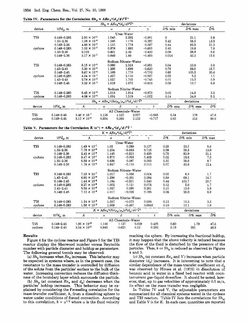
Table IV. Parameters for the Correlation Shp = ARew"(d,ld)ua7 Sh, = ARewn(dp/d)ovT deviations
device i03d,, m A a P Y D% min D% max D 7 0
Urea-Water TIS 0.148-0.283 2.93 x 10⁻³ 1.045 2.292 -0.881 0 21.1 5.8
1.35-2.36 1.58 X 10"' 1.245 1.176 -0.287 0.42 56.5 13.9 0.148-2.36 4.88 x 10⁻⁴ 1.137 1.778 -0.567 0.44 82.9 21.3
1.35-2.36 0.123 0.831 2.39 -0.420 0.08 28.8 9.6 0.148-2.36 3.17 X lo-* 0.849 1.89 -0.493 0.014 42.3 12.6
cyclone 0.148-0.283 1.52 X 0.878 1.892 -0.603 0.45 19.6 7.9
Sodium Nitrate-Water TIS 0.148-0.283 5.15 X 0.980 2.524 -0.951 0.04 23.9 3.0
1.43-2.45 3.50 X 10"' 1.295 1.698 -0.620 0.76 69.0 16.7 0.148-2.45 8.67 x 10⁻⁴ 1.169 1.775 -0.752 0.66 105.5 20.4
cy c 1 on e 0.148-0.283 4.34 x 10⁻³ 1.007 2.116 -0.927 0.02 5.2 1.7 1.43-2.45 2.78 x 10⁻³ 1.027 1.703 -0.745 0.01 13.3 5.9 0.148-2.45 3.52 x 10⁻³ 1.019 1.975 -0.818 0.09 13.7 6.9
Sodium Nitrite-Water TIS 0.148-0.283 6.45 X lo4 1.016 1.914 -0.973 0.02 14.9 3.3 cyclone 0.1484.283 4.08 X 1.051 1.519 -1.022 0.14 24.0 5.3
device i03d,, m A a P Y 6 D% min D% max D% Sh, = A R e w " ( S c ( p , / p w ) ) B ( d p / d ) ~ ~ ~ deviations
All Chemicals-Water TIS 0.148-2.45 3.46 X lo-' 1.135 1.127 2.027 -0.565 0.51 178 47.6 cyclone 0.148-2.45 5.12 X lo4 0.954 0.382 2.123 -0.717 0.62 315 50.0
Table V. Parameters for the Correlation K (s-') = ARew"(d, /d)@e7 K = ARe,"(d,/d)@P
Urea-Water device 103d,, m A a P Y
TIS 0.148-0.283 1.49 x 10⁻⁷ 1.05 0.289 0.127 1.35-2.36 7.79 x 10⁻⁹ 1.254 -0.818 0.716 0.148-2.36 2.43 X 1.145 -0.223 0.439
cy c 1 on e 0.148-0.283 9.47 x 10⁻⁷ 0.871 -0.098 0.409 1.35-2.36 6.59 X 10* 0.830 0.387 0.583 0.148-2.36 1.78 X lo* 0.847 -0.110 0.513
deviations D% D% min D% max
0.29 23.2 5.6 0.08 56.3 13.9 0.79 83.9 21.1 0.02 18.6 7.5 0.35 29.6 9.7 0.07 43.6 12.4
Sodium Nitrate-Water TIS 0.148-0.283 7.25 X 1.017 0.556 0.024 0.02 6.3 1.7
1.43-2.45 6.90 x 10⁻⁹ 1.296 -0.301 0.384 0.50 68.1 16.7 0.148-2.45 1.44 X 1.184 -0.221 0.240 0.44 103.7 20.7
cyclone 0.148-0.283 9.27 X 1.002 0.121 0.078 0.12 5.0 1.7 1.43-2.45 5.58 X 1.027 -0.295 0.261 0.10 13.6 5.9 0.148-2.45 7.15 X 1.017 -0.026 0.188 0.06 20.0 6.9
Sodium Nitrite-Water TIS 0.148-0.283 1.24 X 1.027 -0.075 0.029 0.12 11.2 3.2 cyclone 0.148-0.283 1.56 X lo4 1.009 -0.467 0.0062 0.10 12.1 1.9
device 103d,, m A P Y 6 K = A R e , " ( S c ( p , / p , ) ) ~ ( d , / d ) ~ ~ ~ deviations
a D% min D% max D% All Chemicals-Water
TIS 0.148-2.45 1.95 X lo-' 1.146 1.127 cyclone 0.148-2.45 3.54 X 0.945 -0.621
Results Figure 4 for the cyclone reactor and Figure 5 for the TIS
reactor display the Sherwood number versus Reynolds number with particle diameter and holdup as parameters. The following general trends may be observed:
(a) Sh, increases when Re, increases. This behavior may be expected in systems where, as in the present case, the resistance to the mass transfer is controlled by diffusion of the solute from the particles' surface to the bulk of the water. Increasing convection reduces the diffusion thick- ness of the boundary layer which surrounds the particle.
(b) Sh, (at constant Re, and dp) decreases when the particles' holdup increases. This behavior may be ex- plained by considering the Froessling correlation for the mass-transfer coefficient, k , from a dissolving sphere to water under conditions of forced convection. According to this correlation, k a: u1I2 where u is the fluid velocity
0.029 0.435 0.60 1.79 47.5 0.12 0.293 0.19 265 48.9
reaching the sphere. By increasing the fractional holdup, it may happen that the above velocity is reduced because the flow of the fluid is disturbed by the presence of the particles. Thus, k or Sh, is reduced as observed in Figures 4 and 5 .
(c) Sh, (at constant Re, and V) increases when particle diameter (d,) increases. I t is interesting to note that a similar dependence of the mass-transfer coefficient on d, was observed by Hirose et al. (1976) in dissolution of benzoic acid in water in a fixed bed reactor with coun- tercurrent gas-liquid downflow. It should be noted, how- ever, that, up to gas velocities of approximately 0.5 m/s, its effect on the mass transfer was negligible.
In Tables IV and V, the adjustable parameters are summarized for all chemical systems tested in the cyclone and TIS reactors. Table IV lists the correlations for Sh,, and Table V is for K. In each case, quantities are reported

Ind. Eng. Chem. Res., Vol. 27, No. 10, 1988 1935
it should be noted (Table I1 in the present work) that the pressure drop on the cyclone is almost twice that of the TIS reactor for identical flow rates of water.
(2) For urea-water, the semibatch TIS reactor provides maximal values of k (0.2 X m/s) which are approxi- mately 6 times lower than the values obtained on a con- tinuous TIS reactor (Tamir and Grinholtz, 1987) which was converted to the semibatch reactor. This can be explained by the effect of the inlet pipes in the continuous TIS re- actor with a length of 0.32 m which act as an additional tubular reactor. Moreover, the particles are introduced into the reactor through the inlet pipes at a relatively high velocity as compared to their introduction into the semi- batch system as explained before.
Acknowledgment
mental work. We thank Paulina Weiner for her help in the experi-
which indicate the goodness of fit of the data such as the minimal deviation, Dmin (compared to the experimental value), the maximal deviation, D,,, and the mean value of all deviations, D.
The data were correlated in several ways as follows. All 535 data points, corresponding to all the chemical systems investigated, were correlated by eq 15 and 16, and the parameters are reported a t the bottom of Tables I11 and IV. As noted, the maximal deviations, D,, are very high and the mean value of all deviations is approximately 50%. In order to reduce the deviations between calculated and experimental values, the method of piecewise fitting was applied. The complete interval was divided into several intervals, and the data for each interval were correlated separately. The size of the interval was determined by the desired deviation, dictated by experimental accuracy. Thus, it was decided to correlate each chemical system separately, and in each system the range of particle diam- eters was divided into two intervals. The first range is the so-called "powder rangen, where d, varies between 0.148 X and 0.283 X m.
or (1.43-2.45) X m. In addition, for each chemical system, the data were also correlated for the entire range of particle diameters, (0.148-2.36) X or (0.148-2.45) X m. The interval size appears in Tables IV and V under "range of d;. As expected, deviations between the predicted values of Sh, or K from the experimental values decrease by decreasing the interval of the particle diameter.
Equations 15-18, and the parameters listed in Tables IV and V, cannot be used for scale-up without additional tests on large-scale equipment. In the present work, they were used for evaluating the relative superiority of the cyclone and the TIS reactors by considering the following ratios:
The second interval is approximately (1.35-2.36) X
r = Sh,(cyclone) /Sh,(TIS) r = K(cyc1one) /K(TIS) (19)
The following cases were studied: (a) Re(cyc1one) = Re- (TIS) a t the inlet pipe. This is equivalent to Q(cyc1one) = Q(TIS)/2. (b) Q(cyc1one) = Q(T1S) which is equivalent to Re(cyc1one) = 2Re(TIS). By evaluating the ratios in eq 19 with the parameters listed in Tables I11 and IV, the following trends were observed within the common range of the operating parameters of the reactors:
(1) For urea-water, r >1; hence the cyclone reactor is always superior with respect to dissolution mass transfer.
(2) For sodium nitrate-water, under identical Reynolds numbers, r < 1. Under identical water flow rates, the TIS reactor is preferable under some circumstances, while in other conditions the cyclone reactor is better.
(3) For sodium nitrite-water, which was investigated only for small particle diameter (d, = (0.148-0.283) X lo4 m), r < 1 under almost all operating conditions. This means that the TIS reactor is superior in this respect to the cyclone reactor.
It is useful to compare the performance of the semibatch cyclone and TIS reactors with other available equipment for dissolution of solids. This can be done by considering Table I1 in the work of Tamir and Grinholtz (1987) and in the present research. The following conclusions may be drawn on the basis of the values of the mass-transfer coefficient, k:
m/s or Sh, = 815 for dissolution of sodium nitrate in water. This value is higher than that reported for continuous and semibatch TIS reactors, agitated vessel, and rotating dissolution cell, as well as the trickle bed reactor. However,
(1) The cyclone reactor gives (Table 11) k = 2.5 X
Nomenclature
A = initial surface area of the particles given by eq 8, m2 Ci = solute concentration in water at the inlet to the reactor;
C* = saturation solubility, kg of solute dissolvedlkg of solution Co = maximal concentration in the spectrophotometer re-
sponse curve to a pulse input of particles into the reactor which is also obtained practically at t = 0; C, corresponds to the initial values of particles diameter and holdup (same units as C*)
d = diameter of inlet pipe (2) to the reactor in Figure 1 (0.01 m)
d , = mean spherical particle diameter which is the algebraic mean resulting from measuring the diameter of about 100 particles, m
d, = characteristic length for the hydrodynamic part of the work, defined conveniently as the ratio between the volume of a particle to its surface area and known alzo as "Sauter diameter". For a spherical particle (ac_etal), d, = d,/6; for a cylindrical particle (polyethylene), d , = d / 4 where d is the diameter of a cylindzr; for a rectangular parallellpiped (red plastic particles), d , = ab2/(4ab + 2b2) where a and b are the geometrical dimensions
D% = deviation in percentage; D% = 100(experimental value - calculated value)/experimental value
D% = mean value of all D%; D = CD%/(number of ob- servations)
Dsw = diffusivity of solute in water; see Table I e = specific energy, J/kg of water. The energy needed to transfer water through the reactor in the presence of par- ticles per unit mass of water which is equal to AP,/p,.
Eu = Euler number defined by AF',/p,UW2 Eu,, Eu, = Euler number in the presence of particles and for
g = gravity acceleration, m/s2 iz = initial value of mass-transfer coefficient defined in eq 7
K = initial volumetric mass-transfer coefficient defined in eq
Q = volumetric flow rate of water, m3/s r = defined in eq 19 Re, = Reynolds number based on water flow rate at the
reactor inlet pipe (2) (Figure 1); defined by dU, pw/pw Re, = Reynolds number based on the particles' diameter and
defined by dpUwpw/pw S c = Schmidt number, pw/(p,Jlsw) Sh, = Sherwood number defined by kd IDsw U, = water velocity at the inlet pipe (2p (Figure 1). For a
cyclone U, = Q/(7rd2/4), while for TIS U, = (Q/2)/(*d2/4) = initial holdup of the particles in the reactor, kg
in present experiments, Ci = 0
water flow only, respectively
and 9, m/s
11, s-1
V = dimensionless holdup defined by V/( V,p,)
1936 I n d . Eng. Chem. Res. 1988, 27, 1936-1941
V, = volume of the reactor (6.36 X lo-* m3) W, = mass flow rate of water, kg/s AP = pressure difference (measured) between points 10 and
11 in Figure 1, mHzO APf = pressure drop on the reactor due to friction between
points 10 and 11 in Figure 1, mHzO Up, AP, = pressure drop on the reactor due to friction be-
tween points 10 and ll in Figure l in the presence of particles and in the absence of particles, respectively
Greek Symbols 7 = defined in eq 6 p, = viscosity of water, kg/ms pp, pw = density of particle and water, respectively, kg/m3 Subscripts calc = calculated exp = experimental max = maximal min = minimal p = for particle or in the presence of particles w = for water or in the presence of water Abbreviation TIS = two impinging streams
Literature Cited Elperin, I. T. “Heat and Mass Transfer in Impinging Streams”.
Inzh. Fiz. Zh. 1961, 6, 62-68. Herskowitz, D.; Herskowitz, W.; Tamir, A. ”Desorption of Acetone
in a Two-Impinging-Streams Spray Desorber.” Chem. Eng. Sci.
Hirose, T.; Mori, Y.; Sato, Y. “Liquid-to-Particle Mass Transfer in Fixed Bed Reactor with Cocurrent Gas-Liquid Downflow”. J . Chem. Eng. Jpn. 1976, 9, 220-225.
1987,42, 2331-2337.
Kitron, A.; Buchman, R.; Luzzatto, K.; Tamir, A. “Drying and Mix- ing of Solids and Particles RTD in Four Impinging Streams and Multistage Two Impinging Streams Reactors”. Ind. Eng. Chem. Res. 1987, 26, 2454-2461.
Luzzatto, K.; Tamir, A.; Elperin, I. “A New Two-Impinging-Streams Reactor”. AIChE J . 1984, 30, 600-608.
Tamir, A. “Absorption of Acetone in a Two-Impinging-Streams Absorber”. Chem. Eng. Sci. 1986,41, 3023-3030.
Tamir, A.; Grinholtz, M. “Performance of a Continuous Solid-Liquid Two-Impinging-Streams (TIS) Reactor: Dissolution of Solids, Hydrodynamics, Mean Residence Time, and Hold-up of the Particles”. Ind. Eng. Chem. Res. 1987, 26, 726-731.
Tamir, A.; Herskowitz, D. “Absorption of COP in a New Two-Imp- inging-Streams Absorber”. Chem. Eng. Sci. 1985,40, 2149-2151.
Tamir, A.; Kitron, Y. “Application of Impinging-Streams in Chemical Engineering Processes”. Chem. Eng. Commun. 1987,50,241-330.
Tamir, A.; Luzzatto, K. “Solid-Solid and Gas-Gas Mixing Properties of a New Two-Impinging-Streams Mixer”. AIChE J. 1985a, 31,
Tamir, A.; Luzzatto, K. “Mixing of Solids in Impinging-Streams
Tamir, A.; Shalmon, B. “Scale-up of Two Impinging Streams (TIS)
Tamir, A.; Sobhi, S. “A New Two-Impinging-Streams Emulsifier”.
Tamir, A.; Elperin, I.; Luzzatto, K. “Drying in a New Two-Imping- ing-Streams Reactor”. Chem. Eng. Sci. 1984, 39, 139-146.
Tamir, A.; Luzzatto, K.; Sartana, D.; Salomon, S. “A Correlation Based on the Physical Properties of the Solid Particles for the Evaluation of the Pressure Drop in the Two-Impinging-Streams Gas-Solid Reactor”. AIChE J. 1985, 31, 1744-1746.
Ziv, A.; Luzzatto, K.; Tamir, A. ”Application of Free Impinging- Streams to the Combustion of Gas and Pulverized Coal”. Com- bust. Sci. Technol. 1988, in press.
781-787.
Reactors”. J . Powder Bulk Solids Technol. 198Sb, 9, 15-24.
Reactors”. Ind. Eng. Chem. Res. 1988, 27, 238-242.
AIChE J. 1985, 31, 2089-2092.
Received for review November 5, 1987 Revised manuscript received April 21, 1988
Accepted May 3, 1988
Determination of the Local Voidage Distribution in Random Packed Beds of Complex Geometry
Felix A. Schneider and David W. T. Rippin* Technisch-Chemisches Labor, ETH Zentrum, 8092 Zurich, Switzerland
The voidage fraction distribution in packed beds is visually displayed and recorded by a newly developed optical method that is fast and can be easily demonstrated. It can be used on fixed beds of more complex form than a single packed tube and aids in the understanding of the behavior of new types of reactor configuration. Results are reported for the voidage distribution within a single tube, which are in close agreement with these obtained by other, much more expensive and time- consuming methods. New results are presented for voidage distribution in radial flow configurations not accessible by other methods. The implications for heat transfer in a radial flow reactor are discussed.
1. Introduction A number of different methods are described in the
literature for the determination of the local voidage dis- tribution in packed beds. They can be roughly divided into four classes (Figure 1).
A. Incremental Filling. This procedure, first pro- posed by Shaffer (1952), was improved by Ridgway and Tarbuck (1966): during the stepwise filling of a rapidly rotating cylinder, the void fraction is deduced from the increase in level and volume.
B. Solidification and Stepwise Removal. In this, the most commonly used method, the packing is immo-
* T o whom all correspondence should be addressed.
bilized with a slowly solidifying fluid. The resulting body is progressively reduced by turning in a lathe. To deter- mine the voidage, either the waxy filling material is re- moved from the separated portions again or the propor- tions of the two materials of different density are deduced from the decrease of weight and volume (Roblee et al., 1958; Benenati and Brosilow, 1962; Goodling et al., 1983).
C. Individual Measurement and Enumeration. Another group of experimenters determined the spatial location of the individual particles in the fixed bed and derived the local distribution by integration. Pillai (1977) used for this a two-dimensional bed of flat discs (Cl), and Schuster and Vortmeyer (1980) removed the particles of a packing one by one from above with the sticky end of a movable cylindrical sample probe (C2).
0888-5885/88/2627-1936$01.50/0 0 1988 American Chemical Society