dissolution workstation - chemical analysis, life … workstation operator’s manual 3 contents...
TRANSCRIPT

Dissolution Workstation
Operator’s Manual
Agilent Technologies

Dissolution Workstation Operator’s Manual
Notices© Agilent Technologies, Inc. 2013
No part of this manual may be reproduced in any form or by any means (including electronic storage and retrieval or transla-tion into a foreign language) without prior agreement and written consent from Agi-lent Technologies, Inc. as governed by United States and international copyright laws.
Manual Part Number70-9075
EditionRev A, October 2013
Agilent Technologies, Inc.3501 Stevens Creek Blvd. Santa Clara, CA 95052 USA
Warranty
The material contained in this doc-ument is provided “as is,” and is subject to being changed, without notice, in future editions. Further, to the maximum extent permitted by applicable law, Agilent disclaims all warranties, either express or implied, with regard to this manual and any information contained herein, including but not limited to the implied warranties of mer-chantability and fitness for a par-ticular purpose. Agilent shall not be liable for errors or for incidental or consequential damages in connec-tion with the furnishing, use, or performance of this document or of any information contained herein. Should Agilent and the user have a separate written agreement with warranty terms covering the mate-rial in this document that conflict with these terms, the warranty terms in the separate agreement shall control.
Technology Licenses The hardware and/or software described in this document are furnished under a license and may be used or copied only in accordance with the terms of such license.
Restricted Rights LegendU.S. Government Restricted Rights. Soft-ware and technical data rights granted to the federal government include only those rights customarily provided to end user customers. Agilent provides this custom-ary commercial license in Software and technical data pursuant to FAR 12.211
(Technical Data) and 12.212 (Computer Software) and, for the Department of Defense, DFARS 252.227-7015 (Techni-cal Data - Commercial Items) and DFARS 227.7202-3 (Rights in Commercial Com-puter Software or Computer Software Documentation).
Safety Notices
CAUTION
A CAUTION notice denotes a hazard. It calls attention to an operating procedure, practice, or the like that, if not correctly per-formed or adhered to, could result in damage to the product or loss of important data. Do not proceed beyond a CAUTION notice until the indicated conditions are fully understood and met.
WARNING
A WARNING notice denotes a hazard. It calls attention to an operating procedure, practice, or the like that, if not correctly performed or adhered to, could result in personal injury or death. Do not proceed beyond a WARNING notice until the indicated conditions are fully understood and met.

Contents
Figures 7
1 Installation and Setup 9
Requirements and Configuration 10
PC Requirements 10Software Installation or Upgrade 10Local Security Policy 11
Starting Dissolution Workstation 13
Starting Dissolution Workstation 13Dissolution Workstation Logon 13Adding Users to the Application 14
Workstation Connections 16
Dissolution Apparatus / 8000 / Peristaltic Pump (Daisy-chain to PC) 18
Dissolution Apparatus / 850-DS (Daisy-chain to PC) 19Dissolution Apparatus / 8000 / Syringe Pump (Daisy-chain to
PC) 20Dissolution Apparatus / 8000 / Syringe Pump / Filter Changer
(Daisy-chain to PC) 21Dissolution Apparatus / 8000 / Peristaltic Pump (Individual to
MDS) 22Dissolution Apparatus / 850-DS (Individual to MDS) 23Dissolution Apparatus / 8000 / Syringe Pump (Individual to
MDS) 24Dissolution Apparatus / 8000 / Syringe Pump / Filter Changer
(Individual to MDS) 25
Dissolution Workstation Operator’s Manual 3
Contents
Dissolution Apparatus / 8000 / Peristaltic Pump, Syringe Pump, or Syringe Pump and Filter Changer (Daisy-chain to MDS) 26
Dissolution Apparatus / 850-DS (Daisy-chain to MDS) 27
2 Operation 29
Log On to Dissolution Workstation 30
Configuring Your System 33
Dissolution Apparatus 36Fraction Collector 37Syringe Pump 38Filter Changer 39Completing the Configuration 40Copying a System Configuration 41Deleting a System Configuration 41Recovering a System Configuration 42Serial Numbers 42System Configuration Report 43Editing an Existing System Configuration 44Show Audit Trail 45Verify Integrity 45Import / Export XML File 46
Diagnostics / Manual Control 48
Moving the Drive Unit for Apparatus 3 / Apparatus 7 50Dips per Minute for Apparatus 3 / Apparatus 7 51Moving the Drive Unit for Apparatus 1 / 2 52Spindle Control for Apparatus 1 / 2 53Cannula / Manifold for Apparatus 1 / 2 53Dosage Delivery for Apparatus 1 / 2 54Water Bath Temperature 54Syringe Pump / Filter Changer 55Valve Control (8000) 58
4 Dissolution Workstation Operator’s Manual

Contents
Valve Control (850-DS) 60Peristaltic Pump 61Replacement Media Pump 61
Method Editor 63
Creating a Method 63Copying Methods 75Deleting Methods 75Recovering a Method 75Editing an Existing Method 76Method Report 77Audit Trail 77Import / Export XML File 78
Running the Method 80
Test Reports 85
Electronic Signatures 86
Clean System 87
Manual Sampling 88
MSDE Manager: Back up / Restore Database 90
Backing up the Database 90Restoring the Database 91Tools 92
Security (21 CFR Part 11 Compliance) 96
Change User 96Lock Application 96Audit Trail 97Permissions 98
Index 99
Dissolution Workstation Operator’s Manual 5

Contents
This page was intentionally left blank, except for this message.
6 Dissolution Workstation Operator’s Manual

FiguresFigure 1. Logon 13Figure 2. Local Users and Groups 14Figure 3. Logon 30Figure 4. Dissolution Workstation 31Figure 5. System Configuration 33Figure 6. System Editor 34Figure 7. Serial Numbers 40Figure 8. Serial Number Editor 43Figure 9. Select Item 48Figure 10. System Diagnostics—BIO-DIS 49Figure 11. BIO-DIS Box 50Figure 12. Dipping Speed Box 51Figure 13. Dissolution Tester 52Figure 14. Water Bath Temperature 54Figure 15. FC/SP 55Figure 16. Pump Cycle 56Figure 17. Fill/Dispense 56Figure 18. Change Filters 57Figure 19. Fraction Collector - 8000 58Figure 20. Fraction Collector - 850-DS 60Figure 21. Collector Box - 8000 62Figure 22. Methods 63Figure 23. Method Type Selector 64Figure 24. Method Editor 65Figure 25. Sample Timepoints 70Figure 26. Auto Export 74Figure 27. Select System Step 1 of 2 80Figure 28. Select Method Step 2 of 2 81Figure 29. System Status 82
Dissolution Workstation Operator’s Manual 7

Figures
Figure 30. Method Start Options 83Figure 31. Test Report Selection screen 85Figure 32. Clean System 87Figure 33. MSDE Manager Screen 90Figure 34. MSDE Manager Screen 91Figure 35. Configuration Dialog Security Tab 92Figure 36. Database Tools 93Figure 37. Email 94Figure 38. Miscellaneous 95Figure 39. Lock Application 96Figure 40. Security Audit Trail 97Figure 41. Permissions 98
8 Dissolution Workstation Operator’s Manual

Dissolution Workstation Operator’s Manual
1Installation and Setup
Requirements and Configuration 10
Starting Dissolution Workstation 13
Workstation Connections 16
9Agilent Technologies

1 Installation and Setup
Requirements and Configuration
PC Requirements
The software is designed to run on a PC-based platform with the following minimum specifications:
• 1.5 GHz or faster Pentium 4 processor
• 1 GB of RAM or more
• 16X CD-ROM drive
• 1 USB port (2 if used with a 280-DS)
• 1 RS232 serial port (9-pin) or additional USB port for USB-to-serial adapter
• 60 GB of space on the hard drive
• 1280 x 960 at 16M colors (minimum)
• Microsoft Windows 7 (32-bit and 64-bit) operating system
Software Installation or Upgrade
NOTE If you are upgrading Dissolution Workstation, install the new version, ensure your data has transferred over, and then uninstall the previous version.
NOTE You must log on to the computer as an administrator to set up the software and run it for the first time.
NOTE If Windows User Access Control (UAC) displays during the installation process, click Allow to continue installation.
10 Dissolution Workstation Operator’s Manual

Installation and Setup 1
1 Insert the Dissolution Workstation CD and access the files contained on the CD.
2 Execute setup.exe and follow the on-screen prompts.
Local Security Policy
For 21 CFR Part 11 compliance purposes, you must ensure that the following minimum requirements are met by your system's security policy. To configure your system's security policies, complete the following steps:
1 Click Start > Run.
2 Type secpol.msc and click Enter to run the Local Security Settings Manager. The Local Security Settings screen displays.
3 Click Security Settings > Account Policies > Password Policy and set the applicable security policy configuration.
NOTE When asked if you want to install a particular application (for example, Microsoft .Net Framework,) you are required to click Yes to install all software.
NOTE On the Database Server screen, do not change the password.
NOTE The Local Security Policy conforms with 21 CFR Part 11 physical requirement section 11.300 b. Internal IT requirements may differ from the settings outlined in this section. It may be necessary to coordinate the following configurations with the domain administrator.
Policy Security Setting
Enforce Password History
3 passwords remembered
Maximum Password Length
30 days
Dissolution Workstation Operator’s Manual 11

1 Installation and Setup
4 Click Security Settings > Account Policies > Account Lockout Policy. Configure the options.
5 Click Security Settings > Local Policies > Audit Policy and set the options.
Minimum Password Length
6 characters
Password Must Meet Complexity Requirements
Enabled
Policy Security Setting
Policy Security Setting
Account lockout duration
0 minutes (infinite)
Account lockout threshold
3 invalid login attempts
Reset account lockout counter
99999 minutes
Policy Security Setting
Audit account logon events
Success, Failure
Audit account management
Success, Failure
Audit login events Success, Failure
Audit policy change
Success, Failure
12 Dissolution Workstation Operator’s Manual

Installation and Setup 1
Starting Dissolution Workstation
Starting Dissolution Workstation
1 Double-click the Dissolution Workstation icon on the Windows desktop to start the software.
2 If your system has Windows Firewall enabled, the Windows Security Alert screen displays. Click Unblock to enable the program.
Dissolution Workstation Logon
Figure 1 Logon
1 From the logon screen, enter your credentials in the User ID and Password boxes.
2 Click OK.
3 Click Logon to initiate the software.
NOTE In Windows 7, you must log on to the computer as an administrator to set up the software and run it for the first time.
Dissolution Workstation Operator’s Manual 13

1 Installation and Setup
Adding Users to the Application
1 After successfully logging on to the software, click Tools > Options. The Configuration Dialog screen displays.
• To add a user to a group, select the Security tab on the Configuration Dialog screen.
2 Click User Administration at the bottom of the screen. The Local Users and Groups screen displays.
Figure 2 Local Users and Groups
3 Double-click the Groups folder to expand the list of groups.
4 Double-click all eight of the groups that begin with Vk and ensure that your username is logged in and is identified as a member of these groups.
NOTE To complete this section, you must be logged on as an administrator
14 Dissolution Workstation Operator’s Manual

Installation and Setup 1
5 To add a user to a group, click Add... from the respective group screen. The Select Users, Computers, or Group screen displays.
6 Enter your user identification in the empty box and click Check Names. Ensure your user identification and domain populate the empty field. Click OK.
7 Close the Local Users and Groups screen.
8 Click OK to close the Configuration Dialog screen.
Dissolution Workstation Operator’s Manual 15

1 Installation and Setup
Workstation Connections
There are various ways to connect your dissolution equipment to the Dissolution Workstation software. Each dissolution system requires at least one serial port, or a serial-to-USB adapter. Cable guides are listed with each connection diagram to aid in selecting the necessary cables for your configuration.
Since the software can control up to four complete dissolution systems, it is often necessary to add additional serial ports to the PC controlling the instruments. We recommend the use of either the Edgeport/8 (8 serial DB-9), or Edgeport/416 (4 USB 16 serial DB-9).
The following instructions refer to COM1, COM2, etc. It is acceptable to substitute different COM port numbers based on the physical layout of your system.
NOTE When using the multiport device server, you can connect different dissolution systems based on port availability. This is true with daisy-chain or individual connection. See “Dissolution Apparatus / 8000 / Peristaltic Pump, Syringe Pump, or Syringe Pump and Filter Changer (Daisy-chain to MDS)” on page 26.
Workstation Connection
Peripheral Equipment Procedures
Daisy-chain Connection to PC
8000 / peristaltic pump see “Dissolution Apparatus / 8000 / Peristaltic Pump (Daisy-chain to PC)” on page 18
850-DS see “Dissolution Apparatus / 850-DS (Daisy-chain to PC)” on page 19
8000 / syringe pump see “Dissolution Apparatus / 8000 / Syringe Pump (Daisy-chain to PC)” on page 20
8000 / syringe pump / filter changer
see “Dissolution Apparatus / 8000 / Syringe Pump / Filter Changer (Daisy-chain to PC)” on page 21
16 Dissolution Workstation Operator’s Manual

Installation and Setup 1
Individual Connection to Multiport Device Server (MDS)
8000 / peristaltic pump see “Dissolution Apparatus / 8000 / Peristaltic Pump (Individual to MDS)” on page 22
850-DS see “Dissolution Apparatus / 850-DS (Individual to MDS)” on page 23
8000 / syringe pump see “Dissolution Apparatus / 8000 / Syringe Pump (Individual to MDS)” on page 24
8000 / syringe pump / filter changer
see “Dissolution Apparatus / 8000 / Syringe Pump / Filter Changer (Individual to MDS)” on page 25
Daisy-chain Connection to Multiport Device Server (MDS)
8000 / peristaltic pump, syringe pump, or syringe pump and filter changer
see “Dissolution Apparatus / 8000 / Peristaltic Pump, Syringe Pump, or Syringe Pump and Filter Changer (Daisy-chain to MDS)” on page 26
850-DS see “Dissolution Apparatus / 850-DS (Daisy-chain to MDS)” on page 27
Workstation Connection
Peripheral Equipment Procedures
Dissolution Workstation Operator’s Manual 17

1 Installation and Setup
Dissolution Apparatus / 8000 / Peristaltic Pump (Daisy-chain to PC)
Part Number Quantity
5075-0446 1
5075-0914 1
5075-0252 2
12-0011* 0
* supplied with pump
18 Dissolution Workstation Operator’s Manual

Installation and Setup 1
Dissolution Apparatus / 850-DS (Daisy-chain to PC)
Part Number Quantity
5075-0446 1
5075-0914 1
5075-0252 2
Dissolution Workstation Operator’s Manual 19

1 Installation and Setup
Dissolution Apparatus / 8000 / Syringe Pump (Daisy-chain to PC)
Part Number Quantity
5075-0446 2
5075-0914 1
5075-0252 2
5075-0449 1
20 Dissolution Workstation Operator’s Manual

Installation and Setup 1
Dissolution Apparatus / 8000 / Syringe Pump / Filter Changer (Daisy-chain to PC)
Part Number Quantity
5075-0914 1
5075-0446 3
5075-0252 2
5075-0449 2
Dissolution Workstation Operator’s Manual 21
1 Installation and Setup
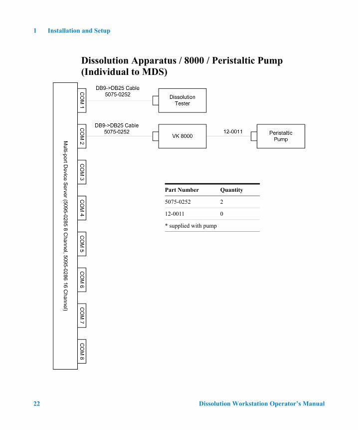
Dissolution Apparatus / 8000 / Peristaltic Pump (Individual to MDS)
Part Number Quantity
5075-0252 2
12-0011 0
* supplied with pump
22 Dissolution Workstation Operator’s Manual

Installation and Setup 1
Dissolution Apparatus / 850-DS (Individual to MDS)
Part Number Quantity
5075-0252 2
Dissolution Workstation Operator’s Manual 23

1 Installation and Setup
Dissolution Apparatus / 8000 / Syringe Pump (Individual to MDS)
Part Number Quantity
5075-0252 2
5075-0448 1
24 Dissolution Workstation Operator’s Manual

Installation and Setup 1
Dissolution Apparatus / 8000 / Syringe Pump / Filter Changer (Individual to MDS)
Part Number Quantity
5075-0252 2
5075-0448 2
Dissolution Workstation Operator’s Manual 25

1 Installation and Setup
Dissolution Apparatus / 8000 / Peristaltic Pump, Syringe Pump, or Syringe Pump and Filter Changer (Daisy-chain to MDS)
26 Dissolution Workstation Operator’s Manual

Installation and Setup 1
Dissolution Apparatus / 850-DS (Daisy-chain to MDS)
Dissolution Workstation Operator’s Manual 27

1 Installation and Setup
This page was intentionally left blank, except for this message.
28 Dissolution Workstation Operator’s Manual

Dissolution Workstation Operator’s Manual
2Operation
Log On to Dissolution Workstation 30
Configuring Your System 33
Diagnostics / Manual Control 48
Method Editor 63
Running the Method 80
Test Reports 85
Clean System 87
Manual Sampling 88
MSDE Manager: Back up / Restore Database 90
Security (21 CFR Part 11 Compliance) 96
29Agilent Technologies
2 Operation
Log On to Dissolution Workstation
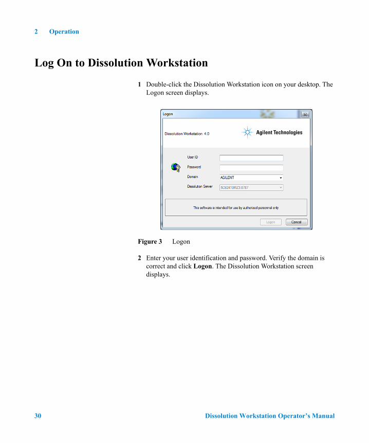
1 Double-click the Dissolution Workstation icon on your desktop. The Logon screen displays.
Figure 3 Logon
2 Enter your user identification and password. Verify the domain is correct and click Logon. The Dissolution Workstation screen displays.
30 Dissolution Workstation Operator’s Manual

Operation 2
Figure 4 Dissolution Workstation
Dissolution Workstation Operator’s Manual 31

2 Operation
The following options are available in the navigation bar on the Dissolution Workstation homescreen:
Option Function
Configuration Create a file for each dissolution apparatus. All relevant data including configuration and component serial numbers is stored within this file.
Diagnostics Verify communication or view real-time data from the modules.
Editor Create a test method to define parameters and tolerances to be verified.
Run Method Begin a test using previously created apparatus and methods.
Test Reports Search and retrieve previously executed tests based on various filtered criteria.
Change User Log on to the Dissolution Workstation Software as a different user.
Lock Application Lock the Dissolution Workstation Software.
Audit Trail Verify, filter, or create reports of logon information for the Dissolution Workstation Software.
Permissions View the rights and privileges for users of the Dissolution Workstation Software.
32 Dissolution Workstation Operator’s Manual

Operation 2
Configuring Your System
It is necessary to configure the components that will be used for automated sample collection. Systems can be added, modified, and removed from the database. All system configuration activity is recorded in the system audit log. The dissolution software allows the configuration of multiple systems. A maximum of four systems can be running methods at one time.
System configuration entails selecting the appropriate equipment and setting the communication and other physical properties of the system. Serial numbers are stored for each system to allow tracking of physical system changes.
1 From the navigation bar, click Configuration. The System Configuration screen displays.
Figure 5 System Configuration
Dissolution Workstation Operator’s Manual 33

2 Operation
2 Click Create. The System Editor screen displays.
Figure 6 System Editor
34 Dissolution Workstation Operator’s Manual

Operation 2
3 Click Next. Following is a description of the System Editor screen options:
4 Click Next. The following sections describe the screens that display based on the selections entered on the System Editor screen.
Option Description
System System Name Enter a name for your system.
Laboratory Enter a laboratory name.
Dissolution Setup Click the drop-down arrow on the Dissolution Setup box to select Apparatus 3/7, Apparatus 1/2/5/6, or NONE.
Click the drop-down arrow in the Dissolution Setup box to select Peristaltic Pump or Syringe Pump.
If your system configuration includes an 8000 or 850-DS, click Fraction Collector.
If your system configuration includes a syringe pump, once Syringe Pump is selected from the drop-down menu above, the Filter Changer option becomes active. Click Filter Changer if your system configuration includes a filter changer.
Restrict Execution To Specified Workstation Click to display the name of the workstation or enter the name of the workstation connected to the system. Click No Restriction to allow the system to be run from any workstation.
Note: the system must be physically connected.
Change Management If applicable, select the box under Change Management in order to restrict the system editing rights to the current user.
Note: This option prevents system configuration modification by anyone other than the system owner or a user with VkModifyOthersSystems privilege.
Dissolution Workstation Operator’s Manual 35

2 Operation
Dissolution Apparatus
1 If applicable, either the BIO-DIS screen or the Dissolution Tester screen displays. Click Next. Depending on the chosen configuration, the following is a description of the screen options available for either Apparatus 1/2/5/6 or Apparatus 3/7:
Dissolution Apparatus
Comm Address Enter the appropriate communication address for the dissolution apparatus.
Options Click the appropriate dissolution apparatus options.
Using the up and down arrows, indicate the number of vessels.
BIO-DIS
Comm Address Enter the appropriate communication address for the dissolution apparatus.
Rows Using the up and down arrows, indicate the number of rows.
Note: this setting must match the physical configuration of the instrument.
Sample Channels Using the up and down arrows, indicate the number of sample channels.
Note: this setting must match the physical configuration of the instrument.
NOTE The communication address (PC port: instrument ID) is comprised of the physical PC COM port (PC port) and the instrument address on the serial bus (instrument ID). For example: COM1:01.
36 Dissolution Workstation Operator’s Manual

Operation 2
Fraction Collector
1 If you selected Fraction Collector, the Fraction Collector screen displays. Enter the appropriate communication address for the fraction collector. When connecting to the PC, enter the com port and comm ID. Verify the comm ID on the fraction collector is set to the same value.
2 Using the up and down arrows, indicate the number of channels.
3 Verify the fraction collector is configured for the proper number of channels.
4 Click Next.
NOTE The communication address (PC port: instrument ID) is comprised of the physical PC COM port (PC port) and the instrument address on the serial bus (instrument ID). For example: COM1:01.
Dissolution Workstation Operator’s Manual 37
2 Operation
Syringe Pump
1 If you selected Syringe Pump, the Syringe Pump screen displays.
Following is a description of the Syringe Pump screen options:
2 Click Next.
3 If you selected Filter Changer, the Filter Changer screen displays.
4 Enter the appropriate communication address for the filter changer. When connecting to the PC, enter COMx:75 (8000 only).
NOTE There is no additional screen if you select Peristaltic Pump since no specific pump parameters are required.
Option Description
Comm Address Enter the appropriate communication address for the syringe pump. When connecting to the PC, enter COMx:76.
Note: If you are using an 850-DS, the com port for the syringe pump has to be same as the 850-DS. Do not change the comm ID of 76.
Current Level (8000 only) Use the up and down arrows to indicate the motor power (current level). The recommended setting is 4.
Calibration Count Use the up and down arrows to indicate the calibration count. This number refers to the number of steps the motor moves to lower the syringe for a full stroke. The recommended setting is 19300 (19000 for the 850-DS).
Plunger Speed Use the up and down arrows to configure the syringe pump plunger to operate at a specific speed.
Note: If an 8000 is configured, steps/sec is used. If an 850-DS is equipped, ml/min is displayed.
Aspiration Dwell Use the up and down arrows to indicate the aspiration dwell time.
Prime Loss Use the up and down arrows to indicate the prime loss volume. This parameter accounts for the volume of sample to travel from the dissolution vessel removed at the sample time point to the sample tubes or vials prior to collection.
Syringe Size Click the drop-down arrow and select the syringe size.
38 Dissolution Workstation Operator’s Manual

Operation 2
5 Click Next.
Filter Changer
1 If you selected Filter Changer, the Filter Changer screen displays.
Following is a description of the Filter Changer screen options:
2 Click Next.
NOTE The communication address (PC port: instrument ID) is comprised of the physical PC COM port (PC port) and the instrument address on the serial bus (instrument ID). In this case x is the physical port number and 75 is the logical instrument identification number.
Option Description
Comm Address Enter the appropriate communication address for the syringe pump. When connecting to the PC, enter COMx:75.
Note: If you are using an 850-DS, the com port for the syringe pump has to be same as the 850-DS. Do not change the comm ID of 75.
Dissolution Workstation Operator’s Manual 39

2 Operation
Completing the Configuration
1 After the final screen specific to your configuration, the Serial Numbers screen displays (see Figure 7, “Serial Numbers,” on page 40).
Figure 7 Serial Numbers
2 From the drop-down menu, select the type of accessory (for example: basket, shaft, paddle, vessel) in the box that corresponds to Type.
3 Enter the serial number for the item and click Add.
4 Repeat steps 2 and 3 for each item selected under Dissolution Setup on the System Editor screen (see “Dissolution Setup” on page 35).
40 Dissolution Workstation Operator’s Manual

Operation 2
5 Click Finish.
6 Repeat all the sections under “Configuring Your System” on page 33 for each additional system.
7 Close the System Configuration screen.
Copying a System Configuration
To copy a system configuration, complete the following steps:
1 From the navigation bar, click Configuration. The System Configuration screen displays (see Figure 5, “System Configuration,” on page 33).
2 Select the desired system configuration.
3 Click Copy.
4 Click Paste. A new system configuration displays. The description of the new system configuration is Copy of....
5 Close the System Configuration screen.
6 To edit the system configuration, see “Editing an Existing System Configuration” on page 44.
Deleting a System Configuration
To delete a system configuration, complete the following steps:
1 From the navigation bar, click Configuration. The System Configuration screen displays (see Figure 5, “System Configuration,” on page 33).
2 Select the desired system configuration.
3 Click Delete.
4 Click Yes.
5 Close the System Configuration screen.
NOTE The system configuration is never physically deleted. It is only marked as deleted in the database.
Dissolution Workstation Operator’s Manual 41

2 Operation
Recovering a System Configuration
To recover a deleted system configuration, complete the following steps:
1 From the navigation bar, click Configuration > Recover. The System Configuration screen displays.
2 Select the desired system configuration.
3 Click OK.
Serial Numbers
To review or add serial numbers to the system configuration, complete the following steps:
1 From the navigation bar, click Configuration. The System Configuration screen displays (see Figure 5, “System Configuration,” on page 33).
2 Select the desired system configuration.
3 Click Serial Numbers. The Serial Number Editor screen displays (see Figure 8, “Serial Number Editor,” on page 43).
NOTE Alternately, you can double click the desired system configuration and double click Next until the Serial Numbers section of the System Editor displays or right click the desired system configuration and select Serial Numbers. Serial numbers can be added or deleted as a result of any of these actions.
42 Dissolution Workstation Operator’s Manual

Operation 2
Figure 8 Serial Number Editor
4 From the drop-down menu, select the type of accessory (for example: basket, shaft, paddle, vessel) in the box that corresponds to Type.
5 Enter the serial number for the item and click Add.
6 Repeat steps 4 and 5 for each item selected under Dissolution Setup (see “Dissolution Setup” on page 35).
7 Click OK. The Serial Number Editor screen closes.
System Configuration Report
To display a report of the system configuration, complete the following steps:
1 From the navigation bar, click Configuration. The System Configuration screen displays (see Figure 5, “System Configuration,” on page 33).
2 Select the desired system configuration.
Dissolution Workstation Operator’s Manual 43

2 Operation
3 Click Report.
4 Select the version. By default, the most recent report version displays.
5 Use the up and down arrows to indicate the desired report version and click OK.
6 The system report displays. The report can be printed, exported, searched, or verified.
Editing an Existing System Configuration
To display and edit the properties of an existing system configuration, complete the following steps:
1 From the navigation bar, click Configuration. The System Configuration screen displays (see Figure 5, “System Configuration,” on page 33).
2 Select the desired system configuration.
3 Click Properties. The System Editor screen displays (see Figure 6, “System Editor,” on page 34).
4 Select the appropriate tabs and change the relevant information in the same manner that the system was created.
5 Click Finish to close the System Configuration screen. If you have made any changes, then upon completion of the wizard, you will be asked to explain or provide a reason for the change to comply with 21 CFR Part 11.
NOTE Alternately, you can right click the desired system configuration and select Report. The Version Selection screen displays as a result of either of these actions.
NOTE Alternately, you can double click the desired system configuration or right click the desired system configuration and select Properties. The System Editor screen displays as a result of any of these actions.
44 Dissolution Workstation Operator’s Manual

Operation 2
Show Audit Trail
To display the audit trail for a system configuration, complete the following steps:
1 From the navigation bar, click Configuration. The System Configuration screen displays (see Figure 5, “System Configuration,” on page 33).
2 Select the system configuration and click Show Audit Trail. The System Audit Trail screen displays.
3 Select two or more versions and click Differences in the navigation bar. A change report displays. The report can be printed or exported.
Verify Integrity
To verify that the system configuration has not been changed outside of the Dissolution Workstation program, complete the following steps:
1 From the navigation bar, click Configuration. The System Configuration screen displays (see Figure 5, “System Configuration,” on page 33).
2 Select the system configuration and click Verify Integrity. Either the data is verified successfully or the user is directed to contact their system administrator.
3 Click OK to close the Data Verification screen.
4 Close the System Configuration screen.
NOTE Alternately, you can right click the desired system configuration and select Show Audit Trail. The System Audit Trail screen displays as a result of either of these actions.
NOTE Alternately, you can right click the desired system configuration and select Verify Integrity. The integrity of the system configuration is checked as a result of either of these actions.
Dissolution Workstation Operator’s Manual 45
2 Operation
Import / Export XML File
To use an existing system configuration from one Dissolution Workstation computer on a different Dissolution Workstation computer, you can export and import the system configuration as an XML file.
To export the system configuration, complete the following steps:
1 From the navigation bar, click Configuration. The System Configuration screen displays (see Figure 5, “System Configuration,” on page 33).
2 Select the desired system configuration.
3 Click Export. The Version Selection screen displays.
4 If applicable, indicate which version to export and click OK. The Export System to XML File screen displays.
5 Indicate the directory and file name and click Save. The code is saved as an XML file.
To import the XML file at another Dissolution Workstation, complete the following steps:
1 From the navigation bar, click Configuration. The System Configuration screen displays (see Figure 5, “System Configuration,” on page 33).
2 Click Import. The Import System from XML File screen displays.
NOTE Alternately, you can right click the desired system configuration and select Export. The Version Selection screen displays as a result of either of these actions.
NOTE Each time a system configuration is saved, a new version is created. To export a version other than the most recently saved, indicate the appropriate version number on the Version Selection screen.
NOTE Alternately, you can right click the desired system configuration and select Import. The Import System from XML File screen displays as a result of either of these actions.
46 Dissolution Workstation Operator’s Manual

Operation 2
3 Select the appropriate directory and file name and click Open. The system configuration displays on the System Configuration screen.
4 Close the System Configuration screen.
Dissolution Workstation Operator’s Manual 47

2 Operation
Diagnostics / Manual Control
To check the diagnostics of a dissolution apparatus, complete the procedures on the following pages. These procedures are performed on one system at a time. Repeat the procedures as applicable for each additional system.
1 Click Diagnostics. The Select Item screen displays.
Figure 9 Select Item
48 Dissolution Workstation Operator’s Manual

Operation 2
2 Select the desired system and click OK. The System Diagnostics screen displays. Depending on the entered system configuration, the tabs may vary (see Figure 10, “System Diagnostics—BIO-DIS,” on page 49).
Figure 10 System Diagnostics—BIO-DIS
NOTE If your system is not responding correctly, click for additional diagnostics. The screen expands to display the raw serial communications between the instruments.
Dissolution Workstation Operator’s Manual 49

2 Operation
Moving the Drive Unit for Apparatus 3 / Apparatus 7
To move the dissolution apparatus drive unit, complete the following steps:
1 Select the BIO-DIS tab (see Figure 10, “System Diagnostics—BIO-DIS,” on page 49).
2 Click any vessel position corresponding to the desired row in the BIO-DIS box (see Figure 11, “BIO-DIS Box,” below). The drive unit moves to the indicated row.
Figure 11 BIO-DIS Box
3 Click . The drive unit returns to the home position.
50 Dissolution Workstation Operator’s Manual
Operation 2
Dips per Minute for Apparatus 3 / Apparatus 7
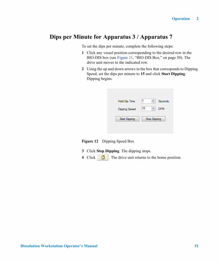
To set the dips per minute, complete the following steps:
1 Click any vessel position corresponding to the desired row in the BIO-DIS box (see Figure 11, “BIO-DIS Box,” on page 50). The drive unit moves to the indicated row.
2 Using the up and down arrows in the box that corresponds to Dipping Speed, set the dips per minute to 15 and click Start Dipping. Dipping begins.
Figure 12 Dipping Speed Box
3 Click Stop Dipping. The dipping stops.
4 Click . The drive unit returns to the home position.
Dissolution Workstation Operator’s Manual 51

2 Operation
Moving the Drive Unit for Apparatus 1 / 2
To move the dissolution apparatus drive unit, complete the following steps:
1 Select the Dissolution Tester tab (see Figure 13, “Dissolution Tester,” on page 52).
Figure 13 Dissolution Tester
2 Click in the Drive Unit box. The drive unit raises.
3 Click . The drive unit stops.
4 Click . The drive unit lowers.
NOTE If your system is not responding correctly, click for additional diagnostics. The screen expands to display the raw serial communications between the instruments.
52 Dissolution Workstation Operator’s Manual

Operation 2
Spindle Control for Apparatus 1 / 2
To set the RPM, complete the following steps:
1 Using the up and down arrows in the box that corresponds to Spindle RPM, set the RPM to the desired speed and click . The spindles begin to turn at the entered RPM.
2 Click . The spindles stop.
Cannula / Manifold for Apparatus 1 / 2
To raise or lower the cannulas / manifold, complete the following steps:
1 Using the up and down arrows, set the cannula position to all cannulas and the volume to 900.
2 Click . The cannulas / manifold raise(s).
3 Click . The cannulas / manifold lower(s).
NOTE If your system configuration includes a V-series Dissolution Apparatus, set the volume and individually raise and lower the cannulas by changing the cannula position.
Dissolution Workstation Operator’s Manual 53
2 Operation
Dosage Delivery for Apparatus 1 / 2
To open the DDMs, complete the following steps:
1 Using the up and down arrows, set the DDM to all DDMs.
2 Click . The DDMs open.
Water Bath Temperature
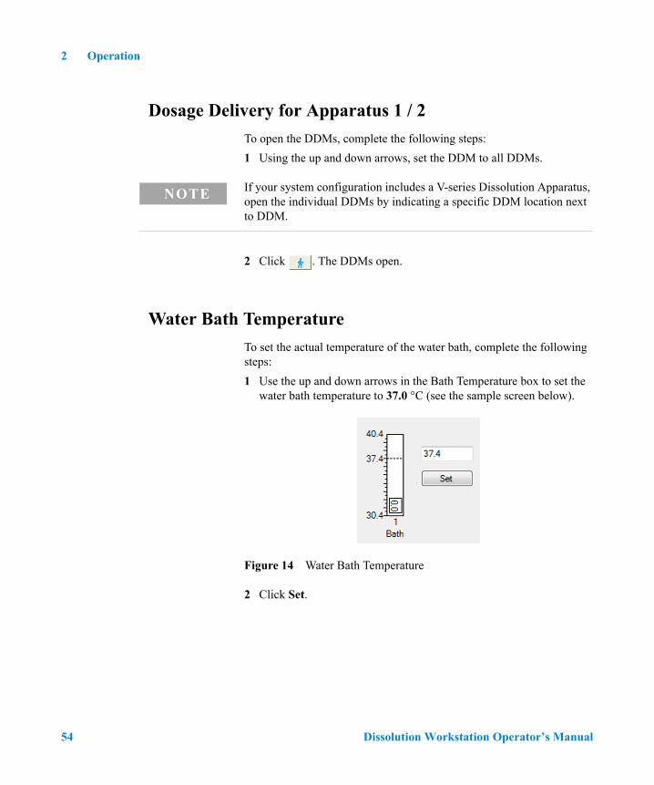
To set the actual temperature of the water bath, complete the following steps:
1 Use the up and down arrows in the Bath Temperature box to set the water bath temperature to 37.0 °C (see the sample screen below).
Figure 14 Water Bath Temperature
2 Click Set.
NOTE If your system configuration includes a V-series Dissolution Apparatus, open the individual DDMs by indicating a specific DDM location next to DDM.
54 Dissolution Workstation Operator’s Manual

Operation 2
Syringe Pump / Filter Changer
Syringe Pump
To control the syringe pump, complete the following steps:
1 Select the FC/SP tab. The following screen displays:
Figure 15 FC/SP
2 Click (set valve to output side) in the Valve Control box. There is an audible click.
set valve toinput side
set valve tooutput side
NOTE If your system is not responding correctly, click for additional diagnostics. The screen expands to display the raw serial communications between the instruments
Dissolution Workstation Operator’s Manual 55

2 Operation
3 Click (set valve to input side) in the Valve Control box. There is an audible click.
4 In the Pump Cycle box, use the up and down arrows to enter a volume in milliliters to draw into the syringes.
Figure 16 Pump Cycle
5 Click in the Pump Cycle box to pull from the sampling cannulas. The syringe pump completes the pump cycle.
6 Click in the Pump Cycle box to pull from the return cannulas. The syringe pump completes the pump cycle.
7 In the Fill / Dispense box, use the up and down arrows to enter a percentage of the syringe to fill.
Figure 17 Fill/Dispense
8 Click to move the syringe plunger to the specified step position. The syringe fills to the percentage indicated.
9 Click to dispense the syringe to the home position. The syringe empties.
56 Dissolution Workstation Operator’s Manual

Operation 2
Filter Changer
To control the filter changer, complete the following steps:
1 Click (open the filter changer clamp) in the Clamp Control box. The clamp opens.
2 Click (close the filter changer clamp) in the Clamp Control box. The clamp closes.
3 In the Change Filters box, use the up and down arrows to enter the number of filters to be replaced.
Figure 18 Change Filters
4 Click to expel the filters. The entered number of filters are expelled and replaced with new filters.
Dissolution Workstation Operator’s Manual 57

2 Operation
Valve Control (8000)
To control the valves, complete the following steps:
1 Select the Fraction Collector tab. The following screen displays:
Figure 19 Fraction Collector - 8000
2 Click (lower the valves) in the Valve Control box to lower the needles. The needles lower.
NOTE If your system is not responding correctly, click for additional diagnostics. The screen expands to display the raw serial communications between the instruments
58 Dissolution Workstation Operator’s Manual
Operation 2
3 Click (raise the valves) in the Valve Control box to lift the needles. The needles rise.
4 Click in the Valve Control box to rinse the valves. The valves move up and down repeatedly.
5 Click Open Valves in the Valve Control box. An audible click is heard. When the valves are open, the green lights on the front panel of the dispensing arm illuminate.
Dissolution Workstation Operator’s Manual 59

2 Operation
Valve Control (850-DS)
To control the valves, complete the following steps:
1 Select the Fraction Collector - 850-DS tab. The following screen displays:
Figure 20 Fraction Collector - 850-DS
2 Click (lower the valves) in the Valve Control box to lower the needles. The needles lower.
3 Click (raise the valves) in the Valve Control box to lift the needles. The needles rise.
4 Click Open Valves in the Valve Control box. An audible click is heard. When the valves are open, the green lights on the front panel of the dispensing arm illuminate.
NOTE If your system is not responding correctly, click for additional diagnostics. The screen expands to display the raw serial communications between the instruments
60 Dissolution Workstation Operator’s Manual

Operation 2
Peristaltic Pump
To control the peristaltic pump, complete the following steps:
1 Click in the Peristaltic Pump box. The pump rotates toward the outlet channel of the peristaltic pump.
2 Click (stop pumping) in the Peristaltic Pump box. The pumping stops.
3 Click in the Peristaltic Pump box. The pump rotates toward the inlet channel of the peristaltic pump.
4 Click (stop pumping) in the Peristaltic Pump box. The pumping stops.
Replacement Media Pump
In the Miscellaneous box, click RM Pump On. The pump runs. Click again to turn off the RM pump.
Dissolution Workstation Operator’s Manual 61

2 Operation
Moving the Fraction Collector Dispensing Position
To control the fraction collector dispensing arm, complete the following steps:
1 Click any vessel position corresponding to the desired row in the Collector box. The desired row is moved into position.
Figure 21 Collector Box - 8000
2 In the Collector box, click . The dispensing arm returns to the home position.
62 Dissolution Workstation Operator’s Manual

Operation 2
Method Editor
Creating a Method
To create a new method, complete the following steps:
1 From the navigation bar, click Editor. The Methods screen displays.
Figure 22 Methods
Dissolution Workstation Operator’s Manual 63

2 Operation
2 Click New Method. The Method Type Selector screen displays.
Figure 23 Method Type Selector
3 Select Apparatus 1/2/5/6, Apparatus 3/7, or No Tester and click OK. The Method Editor screen displays (see Figure 24, “Method Editor,” on page 65).
64 Dissolution Workstation Operator’s Manual

Operation 2
Figure 24 Method Editor
4 Select the Parameters tab.
Dissolution Workstation Operator’s Manual 65

2 Operation
Following is a description of the Parameters tab options:
Option Description
Sample Information Product Name Enter the name of the product.
Notes Enter any relevant notes regarding the sample.
User Defined Labels
Label 1
Label 2
Label 3
The fields in this area have default values of LOT, BATCH, and GROUP. These fields are customizable; enter the information that best serves the needs of the method parameters.
Sampling Parameters
Sample Volume Enter the sample volume in milliliters.
Prime Volume Use this option to set the amount of drawn medium necessary to fill the sampling lines of the entire system.
Enter the prime volume in milliliters.
Purge Volume Use this option to set a purge volume in milliliters that ensures all stranded medium is properly expelled.
Enter the purge volume in milliliters.
Active Channels Enter the number of vessel positions used for sampling.
Samples / Filter Enter the number of samples each filter should process before being discharged.
Replacement Volume If your system configuration includes the VK 8000 with replacement media option, enter the replacement volume in milliliters.
Waste Drop Vol Enter the desired waste drop volume in milliliters.
Note: the drop volume is an amount of sample that is dispensed through the VK 8000 needles prior to dispensing samples into the collection tubes to ensure the needles are purged completely.
Dual Sample Click Dual Sample to pull two samples into two consecutive rows at a single sample timepoint.
66 Dissolution Workstation Operator’s Manual

Operation 2
Error Tolerance (±) Temperature Enter the desired temperature fluctuation limit (±). If the vessel / water bath temperature goes over or under the set temperature by the amount of this tolerance, an error is recorded as part of the results.
If your system configuration includes AutoTemp, the system checks the vessel temperature at each sample timepoint.
For system configurations other than the VK 7030, the system continuously checks the water bath temperature.
Speed Enter the desired speed fluctuation limit (±). If the RPM goes over or under the set speed by the amount of this tolerance, an error is recorded as part of the results.
Clean System After Method Run
Enable Adds a cleaning cycle to the end of the dissolution method.
Vol. Specifies the volume of rinse solution to be pumped through the sampling lines during the cleaning cycle.
Cycles Specifies the number of rinse cycles to be executed.
Rinse Port For 850-DS use only. Specifies that the rinse solution will be pumped from the rinse port of the 850-DS (automated).
Sample Cannula Specifies that the rinse solution will be pumped from the sample cannulas. Requires manual placement of appropriate rinse tray.
Profile Interval Enter the timepoint in hh:mm format at which the temperature and speed settings are recorded.
Note: profile measurements are optional. Values are always recorded at sample timepoints independent of this setting.
Change Management If applicable, select the box under Change Management in order to restrict the method editing rights to the current user or any user with VkModifyOthersMethod.
Option Description
Dissolution Workstation Operator’s Manual 67
2 Operation
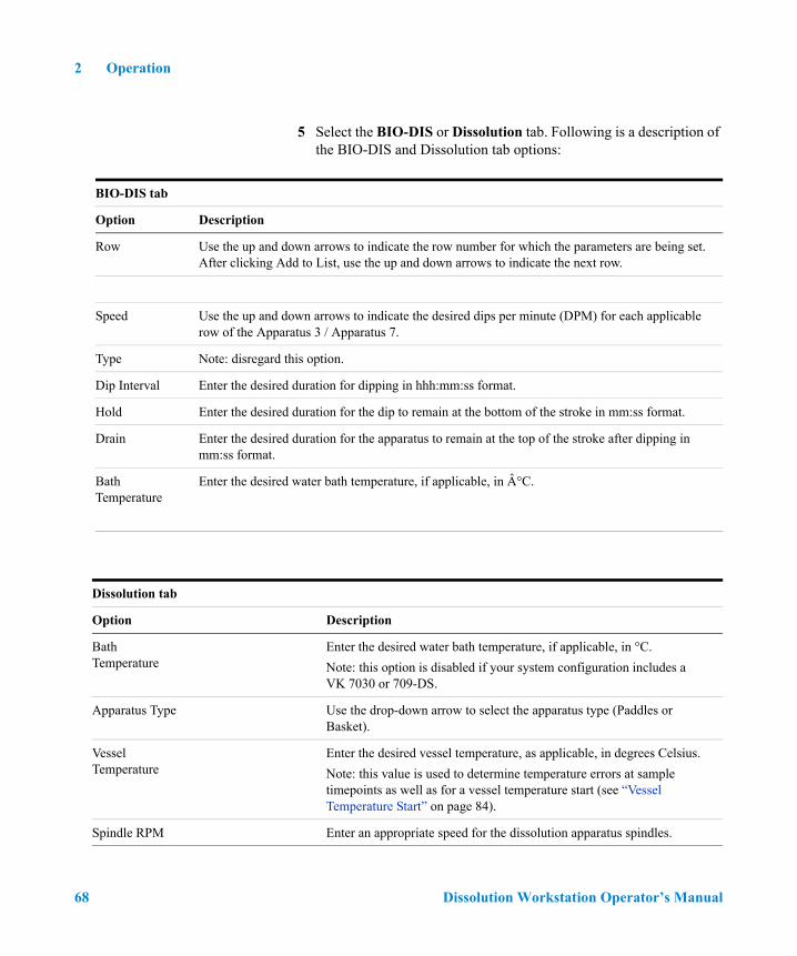
5 Select the BIO-DIS or Dissolution tab. Following is a description of the BIO-DIS and Dissolution tab options:
BIO-DIS tab
Option Description
Row Use the up and down arrows to indicate the row number for which the parameters are being set. After clicking Add to List, use the up and down arrows to indicate the next row.
Speed Use the up and down arrows to indicate the desired dips per minute (DPM) for each applicable row of the Apparatus 3 / Apparatus 7.
Type Note: disregard this option.
Dip Interval Enter the desired duration for dipping in hhh:mm:ss format.
Hold Enter the desired duration for the dip to remain at the bottom of the stroke in mm:ss format.
Drain Enter the desired duration for the apparatus to remain at the top of the stroke after dipping in mm:ss format.
Bath Temperature
Enter the desired water bath temperature, if applicable, in °C.
Dissolution tab
Option Description
Bath Temperature
Enter the desired water bath temperature, if applicable, in °C.
Note: this option is disabled if your system configuration includes a VK 7030 or 709-DS.
Apparatus Type Use the drop-down arrow to select the apparatus type (Paddles or Basket).
Vessel Temperature
Enter the desired vessel temperature, as applicable, in degrees Celsius.
Note: this value is used to determine temperature errors at sample timepoints as well as for a vessel temperature start (see “Vessel Temperature Start” on page 84).
Spindle RPM Enter an appropriate speed for the dissolution apparatus spindles.
68 Dissolution Workstation Operator’s Manual

Operation 2
Final Spin RPM If applicable, enter an appropriate speed for the final spin.
Final Spin Duration
If applicable, enter the duration of the final spin in mm:ss format.
Media Volume Enter the volume of the media in the vessels.
Vessel Temperature
Enable Measure Initial Temperature and / or Measure Final Temperature to take the initial and final vessel temperatures during the method.
Vessel Table Level
Enable Pre-Test Level Verification to verify the vessel table level prior to starting a test (requires a 280-DS Instrument Module).
Operation Checks
Enable Pre-test verification of apparatus components and environment to document the acceptable condition of accessories (MQ requirement).
Vibration Monitoring
Enable Vibration Monitoring
Check this box to enable the detection of transient and persistent vibration levels. Requires the 280-DS Instrument Module.
Defines the range of frequencies that the software will monitor to detect above-threshold amplitudes.
Frequency Bandwidth of Interest
Transient Event Threshold
Defines the limit of the vibration resultant amplitude above which the vibration is considered abnormal. Vibration amplitude threshold can be defined as acceleration measured in mG or displacement measured in mm. Transient event will be detected if the amplitude goes up and quickly resets down.
Persistent Event Threshold
Defines the limit of the vibration resultant amplitude above which the vibration is considered abnormal. Vibration amplitude threshold can be defined as acceleration measured in mG or displacement measured in mm. Persistent event will be detected if the resultant amplitude goes up and stays up over defined period of time.
Dissolution tab
Option Description
NOTE Resultant amplitude is the magnitude of the X, Y, and Z axis amplitudes detected by the 280-DS 3-axis accelerometer:
x2 y+2
z+2
Dissolution Workstation Operator’s Manual 69

2 Operation
6 For the Apparatus 3 / Apparatus 7, click Add To List.
7 For Apparatus 1 / 2, select the Sample Timepoints tab and program the appropriate timepoints (see Figure 25, “Sample Timepoints,” on page 70).
Figure 25 Sample Timepoints
70 Dissolution Workstation Operator’s Manual

Operation 2
Following is a description of the Sample Timepoints tab options:
Option Description
Time Enter the desired sample timepoint in hh:mm:ss format.
Comment Enter any information relevant to the timepoint.
Type Click the drop-down arrow to select either Sample or Sample + Media Change as applicable for your method.
Add Timepoint Once the information is added under Time, Comment, and Type, click Add Timepoint to include the timepoint in the method. Repeat this process for all desired timepoints.
Note: Media change timepoint is a manual media change. It can be media addition or full media replacement. This radio button becomes available to differentiate when Media Change is specified. Selecting Media Addition will maintain a continuous elapsed time while selecting Full Media Replacement assumes the dosage form has been removed from the media and will therefore pause the elapsed time during the change.
Dissolution Workstation Operator’s Manual 71

2 Operation
8 Select the Notifications tab.
72 Dissolution Workstation Operator’s Manual

Operation 2
9 Select the Auto Export tab.
Option Description
Email Addresses List valid email address(es) where the specified notifications should be sent. Separate multiple email addresses with commas.
Notification Options
Errors Notifies user of any errors detected during the dissolution test.
Warnings Notifies user of warnings encountered during the dissolution method.
Status Notifies user of the program status at key points during the dissolution method.
Timepoint Notifies user of the completion of each sample timepoint during the dissolution method.
Dissolution Workstation Operator’s Manual 73

2 Operation
Figure 26 Auto Export
Following is a description of the Auto Export tab options:
10 Click OK to close the Method Editor.
Option Description
Auto Export Destination
Folder Define folder location where exported data should be saved.
File Name Prefix Specify custom file name prefix for name of exported files.
Export Options Specify the data types to be exported to the defined location. Place a check in each box to have the data type exported.
74 Dissolution Workstation Operator’s Manual

Operation 2
Copying Methods
To copy a method, complete the following steps:
1 From the navigation bar, click Editor. The Methods screen displays (see Figure 22, “Methods,” on page 63).
2 Select the desired method.
3 Click Copy Method.
4 Click Paste. A new method displays. The description of the new method is Copy of....
5 To change any of the parameters of the method, see “Editing an Existing Method” below.
Deleting Methods
To delete a method, complete the following steps:
1 From the navigation bar, click Editor. The Methods screen displays (see Figure 22, “Methods,” on page 63).
2 Select the desired method.
3 Click Delete.
4 Click Yes.
Recovering a Method
To recover a deleted method, complete the following steps:
1 From the navigation bar, click Editor > Recover. The Select Deleted Method(s) To Recover screen displays.
2 Select the desired method.
3 Click OK.
Dissolution Workstation Operator’s Manual 75

2 Operation
Editing an Existing Method
To edit a method already entered on the Dissolution Workstation, complete the following steps:
1 From the navigation bar, click Editor. The Methods screen displays (see Figure 22, “Methods,” on page 63).
2 Click the desired method.
3 Click Properties on the navigation bar. The Method Editor screen displays (see Figure 24, “Method Editor,” on page 65).
4 Select the appropriate tabs and change the relevant information in the same manner that the method was created.
NOTE Alternately, you can double click the desired method or right click the desired method and select Properties. The Method Editor screen displays as a result of any of these actions.
76 Dissolution Workstation Operator’s Manual

Operation 2
Method Report
To display a report of the method parameters, complete the following steps:
1 From the navigation bar, click Editor. The Methods screen displays (see Figure 22, “Methods,” on page 63).
2 Select the desired system configuration.
3 Click Report. The Version Selection screen displays.
4 If applicable, indicate which version and click OK.
5 The method report displays. The report can be printed, exported, searched, verified, and / or signed.
Audit Trail
Once a method has completed, the results are available for review, audited modification, and electronic signature. The software maintains complete history for all runs executed on the system. Results can be previewed and printed.
Show Audit Trail
To display the audit trail for a method, complete the following steps:
1 From the navigation bar, click Editor. The Methods screen displays (see Figure 22, “Methods,” on page 63).
2 Select the method and click Show Audit Trail. The Method Audit Trail screen displays.
NOTE Each time a method is saved, a new version is created. To create a report of a version other than the most recently saved, indicate the appropriate version number on the Version Selection screen.
NOTE Alternately, you can right click the desired method and select Show Audit Trail. The Method Audit Trail screen displays as a result of either of these actions.
Dissolution Workstation Operator’s Manual 77

2 Operation
3 Select two or more versions and click Differences in the navigation bar. A change report displays. The report can be printed or exported.
Verify Integrity
To verify that the method has not been changed outside of the application, complete the following steps:
1 From the navigation bar, click Editor. The Methods screen displays (see Figure 22, “Methods,” on page 63).
2 Select the method and click Verify Integrity. Either the data is verified successfully or the user is directed to contact their system administrator.
Import / Export XML File
To use an existing method from one Dissolution Workstation on a different Dissolution Workstation, you can export and import the method as an XML file.
To export the method, complete the following steps:
1 From the navigation bar, click Editor. The Methods screen displays (see Figure 22, “Methods,” on page 63).
2 Select the desired method.
3 Click Export. The Version Selection screen displays.
NOTE Alternately, you can right click the desired method and select Verify Integrity. The integrity of the method is checked as a result of either of these actions.
NOTE Alternately, you can right click the desired method and select Export. The Version Selection screen displays as a result of either of these actions.
78 Dissolution Workstation Operator’s Manual

Operation 2
4 If applicable, indicate which version to export and click OK. The Export Method to XML File screen displays.
5 Indicate the directory and file name and click Save. The code is saved as an XML file which displays in Notepad.
6 Close the Notepad file.
To import the XML file at another Dissolution Workstation, complete the following steps:
1 From the navigation bar, click Editor. The Methods screen displays (see Figure 22, “Methods,” on page 63).
2 Click Import. The Import Method from XML File screen displays.
3 Select the appropriate directory and file name and click Open. The method displays on the Method screen.
NOTE Each time a method is saved, a new version is created. To export a version other than the most recently saved, indicate the appropriate version number on the Version Selection screen.
NOTE Alternately, you can right click the desired method and select Import. The Import Method from XML File screen displays as a result of either of these actions.
Dissolution Workstation Operator’s Manual 79

2 Operation
Running the Method
1 From the navigation bar, click Run Method. The Select System Step 1 of 2 screen displays.
Figure 27 Select System Step 1 of 2
80 Dissolution Workstation Operator’s Manual

Operation 2
2 Select the desired system to run the method and click Next. The Select Method Step 2 of 2 screen displays (see Figure 28, “Select Method Step 2 of 2,” on page 81).
Figure 28 Select Method Step 2 of 2
Dissolution Workstation Operator’s Manual 81

2 Operation
3 Select the desired method to run and click Finish. The system status screen displays (see Figure 29, “System Status,” below).
Figure 29 System Status
Option Description
Start See “Running the Method” on page 80.
Stop See “Running the Method” on page 80.
Diagnostics See “Diagnostics / Manual Control” on page 48.
Load Method
See “Editing an Existing Method” on page 76.
Test Report See “Test Reports” on page 85.
Clean See “Clean System” on page 87.
Manual See “Manual Sampling” on page 88.
82 Dissolution Workstation Operator’s Manual

Operation 2
4 Click Start. The Method Start Options screen displays.
Figure 30 Method Start Options
Dissolution Workstation Operator’s Manual 83

2 Operation
Following is a description of the Method Start Options screen options:
5 Ensure the dongle is inserted into the USB port.
6 Click OK to start the method.
7 When the method is complete, click Test Report. The test report displays. The report can be printed, exported, searched, verified, and / or signed.
Option Description
Product Name Enter the product name.
Notes Enter any appropriate notation.
Label 1Enter the appropriate information based on the user-defined labels (see “User Defined Labels” on page 66).Label 2
Label 3
Dosage Introduction Choose DDM or Manual depending on your configuration.
Temperature Delayed Start
Vessel Temperature Start
Bath Temperature Start
As applicable select Vessel Temperature Start or Bath Temperature Start. Ensure the current date displays in the Time Delayed Start box.
Time Delayed Start Use this option to program a delayed start.
Enter the desired date and time to start the method.
NOTE If the dongle (HASP security key) is not inserted into the USB port, the method will not run.
84 Dissolution Workstation Operator’s Manual

Operation 2
Test Reports
To display a report of the completed method, complete the following steps:
1 From the navigation bar, click Test Reports. The Test Report Selection screen displays.
Figure 31 Test Report Selection screen
2 Click a test in the list to select it.
NOTEBy default, the test report dialog only shows tests done in the previous week. To view tests completed earlier than the previous week, click the Start Date and / or End Date drop-down arrows to indicate date range for a test report selection and click Filter Date and System.
Additionally, you can select a system name from the System combo box to restrict the selection to a particular system.
To restrict the selection to a particular test identification, enter the value in the Test ID Filter box and click Filter Test ID.
Dissolution Workstation Operator’s Manual 85

2 Operation
3 From the navigation bar in the Test Report Selection dialog, click Show Report. The report for the selected test displays.
4 Using the buttons on the report toolbar, you can do the following:
Electronic Signatures
When the user is satisfied with the results, the results can be electronically signed. The software allows multiple electronic signings of a set of results. Each signing is accomplished using the signature dialog box shown. The user authenticity is determined by testing the user identification and password against the Windows security database.
Electronic signatures are permanently linked to the results. The software always requires the signature to be executed using all the signature components. Any attempts to sign a set of results using an invalid user identification, password, or any combination thereof that is incorrect is automatically recorded to the system audit trail.
export
skip to a specific page by numberpreviouspage next
pagelast page
first pageprint
copy
Option Description
Sign Adds electronic signature to test report.
Verify Click to verify integrity of test report. The data verification ensures the report has not been modified outside of the application.
Options Click to specify the optional parameters to display on the test report.
86 Dissolution Workstation Operator’s Manual

Operation 2
Clean System
From the system status screen, click Clean. All instruments initialize. Media is pulled and expelled through the valves. If applicable, the filters are replaced.
Figure 32 Clean System
Option Description
Cleaning Cycle Volume Specify the amount of rinse solution to be cycled through the system (in mL).
Cycles Indicate the number of cycles to be executed to thoroughly rinse the system.
Source Rinse Port Select this option to pull the rinse solution from the Rinse Port (850-DS only).
Sample Cannula Select this option to pull the rinse solution from the sampling cannulas. Manual intervention is required to properly position a rinse tray or cups beneath each sampling cannula.
Dissolution Workstation Operator’s Manual 87

2 Operation
Manual Sampling
Option Description
Sampling Parameters
Sample Volume Enter the sample volume in milliliters.
Prime Volume Use this option to set the amount of drawn medium necessary to fill the sampling lines of the entire system.
Enter the prime volume in milliliters.
Purge Volume Use this option to set a purge volume in milliliters that ensures all stranded medium is properly expelled.
Enter the purge volume in milliliters.
Samples / Filter Enter the number of samples each filter should process before being discharged.
Replacement Volume If your system configuration includes a fraction collector with replacement media option, enter the replacement volume in milliliters.
88 Dissolution Workstation Operator’s Manual

Operation 2
Waste Drop Vol Enter the desired waste drop volume in milliliters.
Note: the drop volume is an amount of sample that is dispensed through the VK 8000 needles prior to dispensing samples into the collection tubes to ensure the needles are purged completely.
Dual Sample Click Dual Sample to pull two samples into two consecutive rows at a single sample timepoint.
Error Tolerance (±) Temperature Enter the desired temperature fluctuation limit (±). If the vessel / water bath temperature goes over or under the set temperature by the amount of this tolerance, an error is recorded as part of the results.
If your system configuration includes AutoTemp, the system checks the vessel temperature at each sample timepoint.
For system configurations other than the VK 7030, the system continuously checks the water bath temperature.
Speed Enter the desired speed fluctuation limit (±). If the RPM goes over or under the set speed by the amount of this tolerance, an error is recorded as part of the results.
Profile Interval Enter the timepoint in hh:mm format at which the temperature and speed settings are recorded.
Note: profile measurements are optional. Values are always recorded at sample timepoints independent of this setting.
Fraction Collector Row Specify the sample tray row where the sample should be delivered.
Dissolution Tester RPM Specify the speed (RPM) of the dissolution apparatus.
Bath Specify the bath temperature of the dissolution apparatus.
Vessel Volume Specify the volume of media contained in the dissolution vessels.
Option Description
Dissolution Workstation Operator’s Manual 89

2 Operation
MSDE Manager: Back up / Restore Database
Backing up the Database
To back up the database, complete the following steps:
1 Click Start > All Programs > Agilent> Dissolution > MSDE Manager. The MSDE Manager screen displays.
Figure 33 MSDE Manager Screen
2 Click Connect to connect to the database.
3 The DB Utility screen displays indicating the database has connected successfully.
4 Ensure the name of the database appears and is highlighted in the Database Name field. If this field is empty, select the Attach tab and click Attach to attach to the database.
90 Dissolution Workstation Operator’s Manual

Operation 2
5 Click ... to specify a destination for the backup file.
6 Click Backup. The back-up file is written to the designated file location.
Restoring the Database
The Dissolution Workstation database can be restored from a previous back-up file. Ensure the Dissolution Workstation program is not running and that no other program is using the database during the restoration.
To restore the database, complete the following steps:
1 Click Start > All Programs > Agilent > Dissolution > MSDE Manager. The MSDE Manager screen displays.
Figure 34 MSDE Manager Screen
2 Click Connect to connect to the database.
3 On the Restore tab, click ... to search for the back-up file.
Dissolution Workstation Operator’s Manual 91

2 Operation
4 Select the appropriate file and click Open.
5 Click Restore. The previous back-up file is restored.
Tools
Configuration Dialog
Select Tools > Options from the Dissolution Workstation homescreen to display the Configuration Dialog screens.
Figure 35 Configuration Dialog Security Tab
92 Dissolution Workstation Operator’s Manual

Operation 2
Database Tools
Select Tools > Options > Database from Dissolution Workstation to display the Database Tools screens.
Figure 36 Database Tools
Option Function
Dissolution Server Name of the dissolution server where the database is located.
Integrated Security
Allows you to assume responsibility for administrating database access.
Change DB Settings
Updates the current settings of the database.
Dissolution Workstation Operator’s Manual 93

2 Operation
Select Tools > Email from Dissolution Workstation to display the Database Tools screens.
Figure 37 Email
Option Function
Server Specify name of outgoing mail server
Port Specify the SMTP host port number.
User Name Enter the user name if the SMTP server requires authentication.
Password Enter the password IF the SMTP server requires authentication.
From Enter a return address for the email.
To Enter a destination address for the email.
Test Test the email configuration settings.
94 Dissolution Workstation Operator’s Manual

Operation 2
Miscellaneous
Select Tools > Miscellaneous from Dissolution Workstation to display the Database Tools screens.
Figure 38 Miscellaneous
Option Function
Use Simulated Instruments
Runs the software in a simulation mode with simulated instruments. No official data is acquired in this mode.
Idle Minutes Amount of time before the software locks automatically. Setting this value to 0 disables this feature.
Dissolution Workstation Operator’s Manual 95

2 Operation
Security (21 CFR Part 11 Compliance)
Change User
1 To change the current user account logged in to the software, click Change User from the Dissolution homescreen.
2 Enter login information and click Logon.
Lock Application
1 To lock the application, click Lock Application from the Dissolution Workstation homescreen.
2 To unlock, click the lock icon and log back into the software.
Figure 39 Lock Application
96 Dissolution Workstation Operator’s Manual

Operation 2
Audit Trail
Click Audit Trail from the Dissolution Workstation homescreen to access the Security Audit Trail screen.
Figure 40 Security Audit Trail
Option Function
Show Report Creates a detailed report of Security Audit Trail activity based on the date range specified.
Retrieve Records Allows for record retrieval of the specified Security Audit Trail activity.
Dissolution Workstation Operator’s Manual 97

2 Operation
Permissions
Review the permissions granted to the current user.
Figure 41 Permissions
98 Dissolution Workstation Operator’s Manual

Index
Numerics21 CFR Part 11 Compliance, 96
AAdding Users to the Application, 14ample, 70Audit Trail, 32, 77, 97Auto, 74
BBacking up the Database, 90Bath Temperature box, 54BIO, 68BIO-DIS box, 50
CCannula / Manifold, 53Change Filters box, 57Change Management, 67Change Server, 93Change User, 32, 96Clean System, 87Collector box, 62Completing the Configuration, 40Configuration Dialog, 92Configuring Dissolution
Workstation, 33Copying a System Configuration, 41Copying Methods, 75Creating a Method, 63
DDatabase
Backing up, 90Restoring, 91
Database Server, 93Database Tools, 93Deleting a System Configuration, 41Deleting Methods, 75Diagnostics, 32diagnostics, 48Dipping Speed box, 51Dips per Minute, 51Dissolution, 68
Workstation Logon, 13Dissolution Apparatus, 32, 36Dissolution Workstation screen, 31Dosage Delivery, 54
EEditing an Existing Method, 76Editing an Existing System
Configuration, 44Electronic Signatures, 86Error Tolerance, 67, 89Export XML File, 46, 78
FFill / Dispense box, 56Filter, 26, 39Filter Changer, 57Fraction Collector, 37
IIdle Minutes, 95Import XML File, 46, 78
LLocal Security Policy, 11Lock Application, 32, 96Logon, 30Logon screen, 30
MMethod Editor, 32Method Editor screen, 65Method Report, 77Method Start Options screen, 83Method Type Selector screen, 64Methods screen, 63Moving the Drive Unit
Apparatus 3 / Apparatus 7, 50Dissolution Apparatus, 52
Moving the Fraction Collector Dispensing Arm, 62
MSDE Manager, 90
PParameters, 66PC Requirements, 10Peristaltic, 18, 22, 26Peristaltic Pump, 61Permissions, 32, 98Profile Interval, 67, 89Pump Cycle box, 56
RReplacement Media Pump, 61report toolbar, 86Requirements and Configuration, 10Restoring the Database, 91Retrieve Records, 97
Dissolution Workstation Operator’s Manual 99

Index
Run Method, 32, 80
SSample, 71Sample Information, 66Sampling Parameters, 66, 88screen, 36screen options
Method Start Options screen, 84System Editor, 35
Security, 96Select Item screen, 48Select Method Step 2 of 2 screen, 81Select System Step 1 of 2 screen, 80Serial Number Editor screen, 43Serial Numbers, 42Show Audit Trail, 45, 77Show Report, 97Software Installation, 10Spindle Control, 53Starting Dissolution Workstation, 13Syringe, 20, 21, 24, 25, 26, 38Syringe Pump, 55System Configuration Report, 43System Configuration screen, 33System Diagnostics
BIO-DIS tab, 49Dissolution Tester tab, 52FC/SP tab, 55Fraction Collector tab, 58, 60
system editing rights, 35System Editor
Serial Numbers screen, 40System Editor screen, 34System status screen, 82
TTest Report Selection screen, 85Test Reports, 32, 85
Uunpacking your equipment, 29
Use Simulated Instruments, 95
VValve Control, 58, 60Verify Integrity, 45, 78
WWater Bath Temperature, 54
100 Dissolution Workstation Operator’s Manual